1
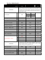
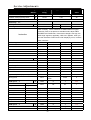
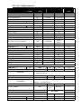
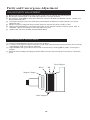
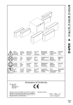
SERVICE MANUAL
3P 5 1 CHASSIS
Design and specifications are subject to change without prior notice.
( ONLY REFERRENCE)
_____
ENGINEER BY:
_____
CHECKED BY:
PPROVED BY:
_____
Service Adjustments
" "
-13 -
Service Adjustments
3P51 ADJUST MENU
1.FACTORY MODE:
(1)Assembly line adjust mode: Press S.M.,
(DISPLAY) and
keys in turn to enter
this mode.
(2)Engineer adjust mode: Press CLOCK, P.M. and
keys in turn to enter this mode. This
mode is usually for R&D and engineering department use.
(3)Press digital keys to enter every adjust page, use PROG+/- keys to pick adjust items, use
VOL+/- keys to adjust the value.
(4)Press DISPLAY to quit factory mode.
2.B+ VOLTAGE ADJUST
Measure C600A + voltage, adjust VR641 to get proper B+ voltage according to CRT
assembly list requirement.
3. RF AGC VOLTAGE ADJUST
(1)Receive 294.25MHz,60dBcolor bar signal.
(2)Enter factory mode and press digital key “4”.
(3)Measure tuner AGC point voltage, adjust AGC item till the voltage is 2.4V,or till picture
noise just disappears。Usually the AGC value is fixed to 27.
4、 FINE ADJUST:
(1) FOCUS ADJUST
a. Receive cross-hatch pattern signal。
b. Set picture to“ RICH” mode。
c. Adjust FBT’s FOCUS knob till picture is clear。
(2) SCREEN VOLTAGE ADJUST(KEY 0 ):
a. Set picture to“STANDARD”mode,without signal input;
b. Enter factory mode and press digital key”0”
c. Adjust FBT’s SCREEN knob till VG2 voltage flag changes between “LOW” and
“HIGH”,press PROG+ key to enter other menu。
(3)
HORIZON ADJUST(KEY 1 ):
a. Receive 50HZ monoscope PATTERN. Set TV to standard mode. Press KEY1 to enter
factory mode
b. Adjust 5HSH(for 60Hz picture,its is 6HSH)to set picture horizontal center to CRT
horizontal center.
c. Receive 60HZ monoscope PATTERN, repeat above b item
-14-
Service Adjustments
(4)VERTICAL&YUV/RGB HORIZON ADJUST(KEY2 ):
5VSL 50HZ vertical linearity
5VSH 50Hz vertical center
6VSL 60HZ vertical linearity
6VSH 60HZ vertical center
5SCL
5VAM
6SCL
6VAM
50Hz vertical slope correction
50Hz vertical size
60HZ vertical slope correction
60HZ vertical size
a. Receive 50Hz cross hatch signal, set TV to STANDARD mode, press digital key “2”
after enter factory mode, adjust 5VSL so that picture’s vertical line is just at the
bottom of the half picture.
b. Adjust 5VSH to set picture vertical center to CRT center.
c. Adjust 5SCL to set proper vertical linearity
d. Adjust 5VAM to obtain picture’s vertical re-display ratio more than 90% .
e. If necessary, fine adjust above items.
f. Receive 50HZ RGB or YUV cross hatch signal,set TV to STANDARD mode,adjust
5RGH till picture horizontal center is at the CRT center.(OPTION)
g.
h. Receive 60Hz cross hatch signal, repeat above a,b.
f.Receive 60HZ RGB or YUV cross hatch signal,repeat above items.(OPTION)
(5)
OSD POSITION:
4-6-1 Menu OSD position adjustment: Receive 50/60HZ cross hatch pattern. Set
TV standard status. Press KEY 2 in factory mode, adjust 5VOF/6VOF and
HOF item, to obtain menu OSD at the center of CRT screen;
4-6-2 LOGO position adjustment: Receive 50/60HZ cross hatch pattern. Set TV
standard status. Press KEY 7 in factory mode, adjust XMIN,XMAX,YMIN,
and YMAX item, to obtain LOGO at the center upto 1/3 of CRT screen.
4-6-3 TELETEXT OSD position adjustment: Receive 50/60HZ TELETEXT signal.
Set TV standard status. Press KEY 7 in factory mode, adjust TXMI and
5TYM/6TYM item, to obtain INDEX at the center of CRT screen.
4-2
White Balance Adjustment (Applied in factory)(KEY 3 )
Normally, this chassis can auto adjust white balance, but for some CRT need to adjust
white balance carefully by hand,Set BRIGHTNESS and CONTRAST at normal status ,
receive GREY SCAL and entering factory mode press KEY 3, set WPR at 31, adjust WPG
and WPR to obtain white balance.
4-3
RF.AGC ADJUSTMENT(KEY 4 )
4-3-1 Receive 60dB RF signal. Connect Digital voltmeter positive terminal to
tuner AGC terminal and negative terminal to GND.
4-3-2 Enter the AGC item in factory mode by the REMOTE CONTROL.
Method:Press key S.M.,
,
-15-
in turn to enter factory mode, then
Service Adjustments
press key “4” and select AGC item by PROG+/-.
4-3-3 Adjust “VOL+” and “VOL-“ keys to obtain 2.4V Digital voltage meter
reading or just no NOISE on screen。
Press key “
” to exit factory mode!。
5、E2PROM INITIALIZTION
(1)
E2PROM initialization (KEY 8 ):
We can use an empty E2PROM when making the sample TV or repairing,also can use
the E2PROM which has been full of data,but you must follow the steps below to
initialize the E2PROM.
in turn to enter the factory mode。Press KEY
Press the keys CLOCK , P.M.,
8,VOL +/- in turn,you may see the OSD”BUSY” after the“INIT”on the
screen。About a while, the character
“BUSY”will disappear,
then POWER OFF
and ON the TV,the initialization is completed。
(2)
FUNCTION SETTING (KEY 5 )
Press the keys “CLOCK” , “P.M.”, “
” in turn to enter the factory mode。Press KEY 5 to
enter the setting menu。
b.Set values to OPTION 1- OPTION 7
c.LOGO setting when powered on or no signal:Press key CLOCK in factory menu
to enter the LOGO edit mode,there are two rows,the 1st can set the
customer’s name etc,and the 2nd row can set to display the customer’s
e-mail, phone…。Press the keys “PROG +/- ”to select the character to
edit,use keys “VOL+/-” to choose the charater.
The detailed instruction of 3P51
Some items displayed but not mentioned below is not used in 3P51 chassis.
.Item
Information of the factory menu
Storage
Display
address
string
RELEASE2.0;
Range (Index | value)
Default
value
Software Version
Fixed, not
changeable
Drect key “8”
Initialization
initialize
uninitialize
INIT
1
0
0
Press key “VOL +”,you can see the character ”INIT BUSY” is
active,Exit the menu and turn off the TV after the character
Instruction
disappearing,reopen it can have a success to innitialize。Then
the program has been storaged in the memorizer,and then need
to readjust the parameter of the factory menu。
-16-
Service Adjustments
.Item
Storage
Display
address
string
Range (Index | value)
Default
value
Drect key “0”
Screen Voltage
A level bright line
Adjust the screen voltage under Tv standard mode and no signal
Instruction
input,just can see the line is ok。
Drect key “1”
Horizontal paralellogram 50Hz
29
5PAR
0-63
31
Horizontal bow 50Hz
2A
5BOW
0-63
31
The above value be adjusted±10 can be OK,the default value is31
Instruction
Horizontal shift 50Hz
2B
5HSH
0-63
19
EW width
2C
5EWW
0-63
33
EW parabola/width 50Hz
2D
5EWP
0-63
19
EW upper corner parabola 50Hz
2E
5UCR
0-63
33
EW lower corner parabola 50Hz
2F
5LCR
0-63
18
EW trapezium 50Hz
30
5EWT
0-63
43
Horizontal paralellogram 60Hz
37
6PAR
0-63
31
Horizontal bow 60Hz
38
6BOW
0-63
31
Horizontal shift 60Hz
39
6HSH
0-63
31
50Hz
The above value be adjusted±10 can be OK,the default value is31
Instruction
EW width
60Hz
3A
6EWW
0-63
33
EW parabola/width 60Hz
3B
6EWP
0-63
19
EW upper corner parabola 60Hz
3C
6UCR
0-63
44
EW lower corner parabola 60Hz
3D
6LCR
0-63
10
EW trapezium
3E
6EWT
0-63
44
Vertical slope 50Hz
31
5VSL
0-63
31
Vertical amplitude 50Hz
32
5VAM
0-63
10
S-correction 50Hz
33
5SCL
0-63
31
60Hz
Drect key “2”
Instruction
generally ,SCL can be setted to be31。
Vertical shift 50Hz
34
5VSH
0-63
22
Horizontal shift 50Hz on RGB mode
35
5RGH
0-63
38
OSD vertical position offset 50Hz
36
5VOF
0-63
38
Horizontal shift on RGB mode generally between 30 to 42,the
Instruction
direct way is to connect the two Tv’s SCART。Adjust the Value
Vertical slope 60Hz
3F
6VSL
0-63
31
Vertical amplitude 60Hz
40
6VAM
0-63
11
S-correction 60Hz
41
6SCL
0-63
31
Vertical shift 60Hz
42
6VSH
0-63
23
Horizontal shift 60Hz on RGB mode
43
6RGH
0-63
38
OSD vertical position offset 60Hz
44
6VOF
0-63
31
OSD horizontal position offset
45
HOF
0-63
42
-17-
Service Adjustments
.Item
Storage
Display
address
string
Vertical zoom
46
Range (Index | value)
Default
value
VX
0-63
32
Adjust this item when lack of vertical amplitude will lead to the
Instruction
picture can’t be full of the screen,then need to adjust the
resistance’s(R318,R319) value.
Direct Key “3”
Black level off-set R
RED
0-63
32
Black level off-set G
GRN
0-63
32
White point R (Direct Key “Red”)
WPR
0-63
31
White point G (Direct Ke“Green”)
WPG
0-63
31
White point B (Direct Key “Blue”)
WPB
0-63
45
The white balance can be adjusted automatically on this
machine,only one or two tube need to be adjusted,generally
the value of RED and GRN between 23 to 39,if adjust
Instruction
excessively will lead the picture faded。(Remark:because of
the higher colour temperature,it’s normal that you feel a little
red。)
Luminance delay time PAL
YDFP
0-15
8
This item has the function to adjust the luminance and colour
Instruction
delay,change the NO. on P card,make the boundary of central
green and purple accord with the border of above gray pane.
Y delay time NTSC
YDFN
0-15
8
Y delay time SECAM
YDFS
0-15
8
Y delay time AV
YDAV
0-15
8
Teletext contrast
TTBR
0-15
15
MUTD
0-20
13
AGC take-over
AGC
0-63
27
UOC Volume
VOL
0-63
56
Mute
delay
time
while
program
switch
Instruction
Direct Key “4”
Input standard RF signal with 1KHz sound ,measure UOC
Instruction
amplitude(location is W101) of output audio RMS value,adjust
VOL till it reaches to 0.5Vrms.
SUB HUE control
IF frequency
Cathode drive level
SHUE
IFFS
HDOL
-18-
0-63
35
38.9MHz
2
38.0MHz
3
0-15
2
2
Service Adjustments
.Item
Storage
Display
address
string
Range (Index | value)
Default
value
Adjust "HDOL" can change the voltage of “R.G.B”obviously,but
adjust too high may lead to fade badly,reverse maybe lead to lack
Instruction
of luminance,so should be careful。Generally it's ok when there is
no black screen or picture faded change the channel under the
maximal beam current
IF AGC speed
SPD
0.7X
0
Normal
1
3X
2
6X
3
1
VG2 Brightness
VG2B
0-63
31
TELETEXT brightness control
TRBI
0-63
25
Contrast –Min pre-set
1CON
0-100
10
Brightness –Min pre-set
1BRI
0-100
10
Colour –Min pre-set
1COL
0-100
0
Sharpness –Min pre-set
1SHP
0-100
0
Contrast –Middle pre-set
2CON
0-100
60
Brightness – Middle pre-set
2BRI
0-100
40
Colour – Middle pre-set
2COL
0-100
45
Direct Key “6”
Sharpness – Middle pre-set
65
2SHP
0-100
60
Contrast – Rich pre-set
66
3CON
0-100
100
Brightness – Rich pre-set
67
3BRI
0-100
100
Colour – Rich pre-set
68
3COL
0-100
100
Sharpness – Rich pre-set
69
3SHP
0-100
100
Volume inflexion Pre-set
VL05
40
VL20
65
VL40
83
VL60
88
VL80
95
If VOL05 set to 40,it means when VOLUME is set to 05 by
user,the internal Volume is 40.This function is used to adjust
Instruction
speaker sound level-VOLUME OSD curve
opening time control
RGBL
0-25
8
Direct Key “7”
Screen saver / Logo Left position
6A
XMIN
0-255
44
Screen saver Right position
6B
XMAX
0-255
186
Screen saver Top position
6C
YMIN
0-63
4
Screen saver Bottom position
6D
YMAX
0-63
37
Teletext Horizontal position
6E
TXMI
0-255
40
-19-
Service Adjustments
.Item
Storage
Display
Range (Index | value)
Default
address
string
Teletext Vertical position 50Hz
6F
5TYM
0-63
38
Teletext Vertical position 60Hz
70
6TYM
0-63
38
71
OP1
0
1
18
Bit 0
AVG
VSD
0
value
Instruction
Direct Key “5”
NVM option 1
VG2 Alignment mode
VG2 is usually set to 0.Receive 49.75MHZ PHILIPS signal.
press key "PM" to set picture to standard mode, adjust FBT's
SCREEN VOLTAGE knob, if the screen voltage is too high, the
Instruction
OSD "high" appears, oppositely, OSD "low" appears, when you
see the characters "HIGH" and "LOW" display by turns, it means
VG2 is well set.
YUV or Yprpb
Bit 1
YUV
Yprpb
1
WIDE BAND SOUND PLL
Bit 2
off
on
0
BLACK STRETCH AMOUNT
Bit 3
10%
20%
0
AV2
Bit 4
off
on
1
SVHS
Bit 5
off
on
0
BLACK STRETCH DEPTH
Bit 6
20IRE
30IRE
0
XX
Bit 7
off
on
0
OP2
0
1
11
AVL
Bit 0
off
On
1
Auto sound in autosearch mode
Bit 1
off
On
1
Pan Europe Teletext set
Bit 2
Off
On
0
Cyrillic Teletext set
Bit 3
Off
On
1
NVM option 2
72
Farsi Teletext set
Bit 4
Off
On
0
Arabic Teletext set
Bit 5
Off
On
0
Sync On Y (YUV/Yprpb mode)
Bit 6
off
on
0
Slicing lever
Bit 7
Fixed
0
NVM option 3
73
dependent on
noise
OP3
0
1
255
Bit 0
Off
On
1
SW1
SW2
English Menu
English Menu
Farsi Menu
Farsi Menu
Bit 1
Off
On
1
Arabic Menu
Arabic Menu
Bit 2
Off
On
1
Turkey menu
Serbian Menu
Bit 3
Off
On
1
France Menu
Bulgaria Menu
Bit 4
Off
On
1
German menu
German menu
Bit 5
Off
On
1
Itality
Itality
Bit 6
Off
On
1
Bit 7
off
on
1
OP4
0
1
114
Narrow-band sound PLL window
Bit 0
small
large
0
Power mode
Bit 1
standby
Last Memory
1
Menu
Russia Menu
Menu
Russia Menu
NVM option 4
74
-20-
Service Adjustments
.Item
Storage
Display
address
string
Range (Index | value)
Default
value
Geometry control
Bit 2
off
On
0
Logo
Bit 3
off
On
0
EHT tracking mode
Bit 4
Vertical
Vert. & EW
1
Search tuing mode sensitivity
Bit 5
Normal
Reduced
1
Menu half-tone
Bit 6
Off
On
1
Zoom function
Bit 7
off
on
0
OP5
0
1
223
Sound system DK
Bit 0
Off
on
1
Sound system BG
Bit 1
Off
On
1
Sound system I
Bit 2
Off
On
1
CORING0
Bit 3
Off
On
1
CORING1
Bit 4
Off
On
1
AV3
Bit 5
off
On
0
Switch-off in vertical overscan
Bit 6
Undefined
Power on to last status
Bit 7
Off
On
1
OP6
0
1
218
“No signal” OSD when no signal
Bit 0
off
On
0
Blue screen or black screen
Bit 1
Black
Blue
1
16:9 mode
Bit 2
off
On
0
Child lock (Lock local key)
Bit 3
Off
On
1
Top & bottom bar on Menu
Bit 4
Off
On
1
Hotel mode
Bit 5
Off
On
No use
Set “POC” bit when no signal
Bit 6
Off
On
1
Game
Bit 7
off
on
1
NVM option 5
NVM option 6
75
76
Instruction
NVM option 7
Vert.
overscan
1
OP6 generally fixed to 218
77
AV1
OP7
0
1
196
Bit 0
off
on
0
Because of AV1 is back AV,if SCART needed,no back AV,
Instruction
need to set AV1 0。
XX
Bit 1
0
1
0
TV and monitor out select
Bit 2
Monitor
TV
1
Because the output of SCART always follow TV,when back AV is
Instruction
SCART,the value set to1。
LISTEN PRESET
Bit 3
off
Power on always
Bit 4
Noise Reduce Off
Bit 5
Noise Reduce On
Bit 6
NTSC-M Control switch
Bit 7
1(FM)
0(QSS)
1
See OP4
bit 1
on
0
Direct On
0
See Table 1
0
1
TrueBass control
78
BASS
off
On
0
Comb-filter Control
79
COMB
Off
On
0
-21-
Service Adjustments
.Item
Storage
Display
Range (Index | value)
Default
address
string
NICAM control
7A
NICA
Off
On
0
RGB Control
7B
RGB
Off
On
1
YUV Control
7C
YUV
Off
On
0
NTSC-M Control
7D
M
off
on
0
value
Direct Key “CLOCK”
Logo edit (7 chars. & 2 lines)
Logo Text
English letter & number
etc
The LOGO edit function will take effect when Bit3 in OP4 set 1,
Instruction
press key ‘VOL+/-“ to choose character,and press PROG+/- to
choose ASCⅡ charater
Table 1 : Noise Reduce Setting for PAL
Noise Reduce On
Noise Reduce Off
OP7 Bit 5
OP5 Bit 6
2.7MHz
3.1MHz
0
0
2.7MHz
3.5MHz
1
0
3.1MHz
3.5MHz
0
1
3.1MHz
3.5MHz
1
1
* Remark : NTSC system preset to 2.7 -> 3.1MHz.
-22-
Purity and Convergence Adjustment
COLOR PURITY ADJUSTMENT
(1) Before color purity adjustment,warm up the TV set over 15 minutes and fully degauss.
(2) Receive pure white signal in AV status and set the TV receiver dynamic.
(3) Go to factory mod MENU2. After write down the values of R-BIAS and B-BIAS, set the values of RBIAS and B-BIAS zero.
(4) Loosen the clamp screw of the deflection yoke and pull the deflection yoke towards color purity
Magnetic loop.
(5) Adjust color purity magnetic loop to make the green area at the center of CRT screen.
(6) Slowly push the deflection yoke toward the front of CRT and set it where a uniform green field is
Obtained. Tighten the clamp screw of the deflection yoke.
(7) Restore the values of R-BIAS,G-BIAS AND B-BIAS.
CONVERGENCE ADJUSTMENT
(1) Receive a dotted pattern. Set the TV receiver dynamic.
(2) Loose the convergence magnet clamperrrrr and align red with blu dots at the center of the screen by
rotating(R,B) static convergence magnets.
(3) Align Red/Blue with green dots at the center of the screen by rotating(RB-G) static convergence
magnet.
(4) Remove the DY wedges and slightly tilt the deflection yoke horizontally and vertically to obtain the
good
Purity Magnet
RB-G
RB
Magnet Clamper
Static Magnet
-23-