1
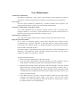
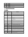
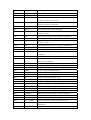
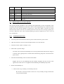
VersaPulse PowerSuite Holmium 20 Watt laser
All View
Control Screen View
Control Screen tabs
Tabs at the bottom of the control screen provide access to the following functions:
Tab
Treatment
Functions
Select ready or standby mode
Set the laser energy (joules)
Set the pulse rate (hertz)
View average power in watts
Set the aiming beam intensity
Select a blinking or continuous aiming beam
View any advisory message
View time of day
Summary
View cumulative treatments and pulses
View summary of either current or previous treatment
View treatment start and end times, number of pulses, total energy delivered to
tissue, and average laser parameters
Start a new treatment
Print treatment summary report-view every laser parameter setting used during the
treatment for a complete case analysis
Options
Select the English or icon viewing mode
Set the date and time
Set the laser beep volume to suit your operating environment
Select 24hour or 12 hour (AM/PM) format
Troubleshooting Guide
If the instrument fails to operate properly, this troubleshooting guide will help you to locate and
correct the malfunction. First, check the following items:
Electrical power source - Verify that the electrical disconnect switch, the circuit breaker, is
turned on.
Laser console electrical – Verify that the laser is on and properly connected to an electrical
service outlet.
External door interlock – If the external door interlock is used in conjunction with a remote
switch, verify that the external door interlock plug is inserted in the external door interlock
receptacle. Close the interlocked door.
Symptom
The laser does not
turn on. The control
screen does not
illuminate.
Inadequate or no
aiming beam.
Probable Cause
The laser is not plugged in.
Plug in the laser
The laser main power circuit
breaker is in the off (down)
position.
Place the laser main power circuit
breaker in the on (up) position, and
wait 5 seconds before turning the key
switch.
The building power (main
electrical service) is turned off.
Turn on the building power.
The electrical outlet is defective.
Use another outlet, or have the outlet
professionally tested and repaired, if
necessary.
The aiming beam is off or set to
low intensity
Adjust the aiming beam intensity.
The delivery system optical fiber
is defective.
Replace the delivery system.
The endoscopic camera light is
too bright (when using an
endoscopic camera with the
delivery system).
Lower the intensity of the camera light.
The debris shield is blown.
Inspect and, if necessary, replace the
debris shield as instructed in the “User
Maintenance” section of the manual.
Note – If your debris shield requires
replacement, you should also replace
your delivery system optical fiber; the
debris shield is typically blown by
failed fibers.
The
aiming
malfunctioning.
No laser power
from end of optical
Suggestion
beam
is
The delivery system optical fiber
is defective.
Contact your local Lumenis service
representative.
Replace the delivery system.
fiber.
The debris shield is blown.
Inspect and, if necessary, replace the
debris shield as instructed in the “User
Maintenance” section of this manual.
Note – If your debris shield requires
replacement, you should also replace
your delivery system optical fiber; the
debris shield is typically blown by
failed fibers.
The laser is malfunctioning.
Contact your local Lumenis service
representative.
“Attach
fiber”
advisory message
appears on the
control screen.
The delivery system laser
connector is not properly
connected to the laser.
Connect the delivery system as
instructed
in
the
“connection
Instructions” section of this manual.
“Attach footpedal”
advisory message
appears on the
control screen.
The footswitch is not properly
connected to the laser.
Connect the footswitch as instructed in
the “Connection Instructions” section
of this manual.
“Check interlock”
advisory message
appears on the
control screen.
The interlock door is open, or the
interlock plug is not properly
inserted.
Close the interlock door, or insert the
interlock plug.
“Insert
debris
shield”
advisory
message appears on
the control screen.
The debris shield is missing or is
not properly inserted.
Insert the debris shield as instructed in
the “User Maintenance” section of this
manual.
! ≤1.5J
△
The laser is in CaseSaver mode.
The maximum energy of 2.5
Joules per pulse is reduced to 1.5
joules per pulse.
When you finish the procedure,
schedule a service call with your local
Lumenis service representative.
The laser is in Service soon
mode. Approximately five or less
treatments remain before service
is required.
Schedule a service call with your local
Lumenis service representative.
The laser is malfunctioning
Press ready or ⊙ to clear the
message. If the condition continues,
turn off the laser for five seconds, then
turn it back on. If the message
reappears, record the advisory code
from the summary screen and contact
your
local
Lumenis
service
representative.
or
! Case saver
△
!
△
Or
! Service Soon
△
!
△
or
!
△
Required
Service
!
△
or
The laser was used at a high
power of an extended amount of
time.
Wait until the message clears. Press
ready or ⊙, and continue to use the
laser. Pause occasionally during
treatment to allow the laser to cool off.
Note – If the laser overheats, do not
turn off the laser. Leaving the laser on
lets the internal cooling system quickly
cool the laser. As the laser cools down,
listen for the internal fan to slow down
to the normal operating speed.
The air flow is restricted.
Verify that the laser is at least 50
centimeters from walls, furniture, or
other equipment.
! Overheating
△
The
treatment
room
temperature is too high.
! >150%
△
or
air
Verify that the treatment room
temperature is between 10℃ and 30
℃.
The energy delivered is more
than 50% higher than the selected
level.
Press ready or ⊙ to clear the
message. If the condition continues,
turn off the laser for five seconds, then
turn it back on. If the condition
persists, contact your local Lumenis
service representative.
The energy delivered is less than
50% of the selected level.
Press ready or ⊙ to clear the
message. If the condition continues,
turn off the laser for five seconds, then
turn it back on. If the condition
persists, contact your local Lumenis
service representative.
The pulse rate delivered is more
than 50% higher than the selected
level.
Press ready or ⊙ to clear the
message. If the condition continues,
turn off the laser for five seconds, then
turn it back on. If the condition
persists, contact your local Lumenis
service representative.
The pulse rate delivered is at
least 20% more than the selected
level.
Press ready or ⊙ to clear the
message. If the condition continues,
turn off the laser for five seconds, then
turn it back on. If the condition
persists, contact your local Lumenis
service representative.
The pulse rate delivered is less
than 50% of the selected level.
Press ready or ⊙ to clear the
message. If the condition continues,
turn off the laser for five seconds, then
turn it back on. If the condition
! Energy high
△
! <50%
△
or
! Energy low
△
!
△
or
! Rate high
△
! >120%
△
or
! Rate 20% high
△
! <50%
△
or
! Rate low
△
! <80%
△
or
! Rate <80%
△
persists, contact your local Lumenis
service representative.
The pulse rate delivered is less
than 80% of the selected level
Press ready or ⊙ to clear the
message. If the condition continues,
turn off the laser for five seconds, then
turn it back on. If the condition
persists, contact your local Lumenis
service representative.
User Maintenance
Annual laser maintenance
Preventative maintenance, safety, power, and calibration check should be performed
annually by a Lumenis-certified service engineer to ensure proper laser performance.
Laser repair
All laser repairs should be performed by a Lumenis-certified service engineer. For
training and information, contact your local Lumenis representative.
Clean the external surface of the laser console
Use a cloth dampened with a noncaustic cleaning solution, such as soap and water,
isopropyl alcohol, or a “hospital - grade” disinfectant, to wipe the external surfaces of
the laser console. Dry with a clean cloth, or allow to air dry.
Clean the laser control screen
Use a soft cloth to apply antistatic glass or plastic cleaner to the laser control screen.
Inspecting the debris shield
If you hear an abnormal popping sound while delivering the treatment beam,
accompanied by a dramatic reduction in treatment effect, the debris shield and the
optical fiber have probably failed; you should immediately stop treatment and inspect
both the debris shield and the fiber.
The debris shield is replaceable part that protects the laser’s optical components from
damage by a failed delivery system. The debris shield is like a fuse: you only need to
replace it if inspection reveals that it is blown.
To inspect the debris shield:
1. Remove the debris shield panel on the laser console.
2. Grasp the debris shield handle, and pull the shield out of the receptacle. (Do not
touch the debris shield optic: finger oil may damage the delicate coatings.)
3. Hold the debris shield toward a light source and look through it, The optic should
appear translucent, smooth, bright, and free of any burn marks, scratches, dust, or
fingerprints. If the optic appears blown, replace the debris shield. (The debris shield
is usually blown by a failed fiber; therefore, always replace your fiber whenever you
replace your debris shield.)
4. If the debris shield is not blown, reinsert the debris shield into the debris shield
receptacle and replace the panel. Attach a new fiber to the laser and resume
treatment. If the abnormal popping sound and decrease in energy persist, contact
your local Lumenis service representative.
5.0 TROUBLESHOOTING
5.1 OVERVIEW
5.1.1
Serviec philosophy
The VersaPulse PowerSuite Holmium 20 Watt laser is designed to require little adjustment or
calibration, and to detect and report hardware malfunctions by fault code or error message,
displayed on the LCD color display. In most cases field failures are repaired by changing out a
Field Replaceable Unit (FRU). FRU’s are built specifically to support field repair, and consist of a
part or group of parts determined to suitable for field replacement. When a part fails that is a part
of a FRU, normally the FRU is replaced, not the individual part.
Corrective and preventive maintenance must only be a accomplished by a Service Engineer who
has completed Lumenis certification service training on the VersaPulse PowerSuite Holmium 20
Watt laser.
The entire optical path is enclosed inside the laser head. Removing the dust cover exposes the
interior to foreign matter (i.e. dust, contaminants and etc). Minimize this exposure by removing
the cover only when necessary, using a clear plastic cover over the head while the dust cover is off,
and getting the dust cover back on as soon as maintenance inside the head is complete.
After power up, and before the VersaPulse PowerSuite Holmium 20 Watt laser moves to its
standby condition, the software performs a series of self test. Self test failures result in fault code
or error messages displayed on the LCD color touchscreen display. These fault codes provide an
indication of what malfunction was detected, which should point to a specific area of the system
for further investigation. Explanation of the fault codes are include in this section. Most hardware
malfunctions will be detected at this time.
During normal operation the software continues to monitor for system malfunctions, and to report
any detected malfunctions by fault code or error message at the LCD color touchscreen display.
Some fault codes are
“Logged” in a special service screen.
The VersaPulse PowerSuite Holmium 20 Watt laser has a series of service software routines
available to the service engineer. The routines are contained in the software EPROM, and are
activated by moving a switch on the Controller PCB(not accessible to the user). These routines
facilitate calibration and troubleshooting. The routines are described in detail later in this section
A service attenuator is mounted in the optics bench assembly and is placed in the beam path by
enabling SW4 on the Controller PCB. The service attenuator can be used during servicing to
decrease the power of the treatment beam before it enters the fiber focus assembly. This can
pervert damage to an attached fiber and/or the blast shield when the laser is fired before the fiber
focus alignment has been confirmed.
The microprocessor circuit includes a four digit, 5x7 matrix LED display mounted on the
Controller PCB. The software can use this display to indicate status or type of fault information to
the service engineer.
5.1.2
Safety Precautions
Lethal Voltages and Ho:YAG laser emissions are the primary dangers to the general safety
precautions which always apply when working on electronics and lasers, the Servicing Engineer
must be aware of the following specific precautions:
Only Lumenis certified VersaPulse PowerSuite Holmium 20 Watt laser Service Engineers
should attempt any service on this system
Even with the keyswitch in the “OFF” position there are potentially lethal voltages present
inside the console.
Storage capacitors inside the system are capable of holding a lethal charge, ever after
power has been removed from the unit.
Do not touch the Ho:YAG Cavity Module – IT IS A SHOCK HAZARD. The Ho:YAG
Cavity Module is electrically isolated from the chassis ground and connected to the
secondary of a transformer to develop an electrical field around the flashlamps. The
Ho:YAG Cavity Module is located in the laser head.
The Ho:YAG laser light is invisible to the human eye. Because the Ho:YAG energy can not
be seen, there is no visible indication of the primary or reflected beam. Eye protection that
attenuates the Ho:YAG wavelength to a safe level must be worn by all persons in the area
of the laser system whenever the laser is being serviced.
The Ho:YAG laser light and its reflections are potential burn hazards and can ignite
flammable materials. Use extreme caution when operating the system with covers opened
or removed. The covers contain the beam and reflections safely within the console. Only
those persons required should be present during servicing, and eye protection that safely
attenuates the Ho:YAG wavelength must be worn by all present.
The Ho:YAG laser light and its reflections are potential hazards to the eye. Use extreme
caution when operating the system with covers opened or removed. The covers contain the
beam and reflections safely within the console. Only those person required should be
present during servicing and eye protection that safely attenuates the Ho:YAG wavelength
should be worn by all those present.
5.2 INTERIOR ACCESS & PARTS LOCATION
Interior access is gained through the front cover (door), which is hinged on the right side. Once the
front cover is opened, the top cover can be removed. Once the top cover is removed the two side
panels can be removed.
Open the front cover to access the DC power supply (mounted inside the door), to access the
Controller PCB, or the remove the top cover or either side cover.
To open the front cover, insert the special tool through the hole on the bottom left of the front
cover. Push up on the tab inside the hole to release the cover (it is hinged on the right side).
Remove the top cover to access the laser head (optics bench), to access the coolant fill reservoir or
to remove either side cover.
To remove the top cover, first open the front cover, then remove the two screws located as shown
in the drawing on the succeeding pages.
Remove optic bench cover to access the Attenuator PCB, Optics Bench PCB, Servo Motor PCB
and all of the optical/mechanical components. Removing the cover exposes the optics bench to
airborne contamination. The optics that operate on the Ho:YAG beam are particularly susceptible
to damage associated with optics surface contamination. Remove this cover only when necessary.
If the cover must be removed, be careful to minimize exposure of the optics bench interior to
external contamination.
To remove the optics bench cover, loosen the screws located along the bottom edge of three sides,
then lift the cover up.
Remove the right side cover to access the fuses, AC Control PCB, main contactor, the circuit
breaker, HVPS, Tachometer PCB, and to access the interior of the enclosure.
To remove the right side cover, open the front cover, remove the top cover, remove the single
screw that secures the cover at the bottom just in front of the rear wheel, then remove the six
screws along the top and front of the cover (three along the top, three along the front). The cover
can then be lifted off of the frame.
Remove the left side cover to access most of the cooling system components.
To remove the left side cover, open the front cover, remove the top cover, remove the single screw
that secures the cover at the bottom, just in front of the rear wheel, remove the six screws along
the top and front of the cover (three along the top, three along the front), then carefully pull the
cover off.
5.3
SERVICE MODE
The VersaPulse PowerSuite Holmium 20 Watt includes “service mode” software routines. Service
mode provides the Servicing Engineer with a number of troubleshooting and maintenance aids,
commonly referred to as service screens. Some system faults are ignored in service mode (see
5.4.3).
To enter into service mode, the microprocessor must see an OFF to ON transition of the Controller
PCB SW2. SW2 is located on the left side of the Controller PCB. Note that if the switch is left on
when the system is powered up, it will not enter into service mode (no OFF to ON transition). If
the microprocessor is halted (some fault are handled by halting the microprocessor) the service
switch will not work – restart the microprocessor (press the reset switch SW5 on the Controller
PCB) then toggle the service switch OFF to ON.
5.4 FAULT ISOLATION
Failures/malfunctions fall into the following general categories:
The system fails to turn on properly, or shuts off when it should not. See section 5.4.1.
The system turns on, by the Control Panel display and/or operating controls do not respond
properly, and no fault code is displayed. See section 5.4.2.
During power up tests, or during operation, the system displays one or more error codes.
See section 5.4.3.
During power up self tests the system fails to pass autocalibration See Section 5.4.4.
5.4.1
Turn On and Shut Down Fault Isolation
System “turn-on” problems occur when the system fails to turn on and stay on with activation of
the key switch. System “Shutdown” refers to the system main contactor de-energizing after the
system has successfully turn on.
If the system fails to turn on, determine if there is power to the unit and through the circuit breaker
to the main contactor and isolation transformer. Determine if the main contactor is energizing
when the keyswitch is held in the start position (do the system fan and pump start running?). If not,
check the circuit breaker, isolation transformer thermal switch and fuses F8/F9 and F12.
If the system shuts down after being turned on, and the circuit breaker is not tripping, use the
Interlock schematic in Section 8 to troubleshoot the main contactor interlock loop. Note that the
software and microprocessor can turn off the main contactor. The 24V DC loop to the main
contactor can be broken by the thermal switch in the isolation transformer, the keyswitch, hold on
relay K2, or the fuse F12.
If the circuit breaker is tripping, check for proper transformer tapping. If the tripping is associated,
with firing (or charging of the main capacitor), it is probable associated with the HVPS. If not,
attempt to isolate the tripping to one of the isolation transformer secondary loads by removing
fuses (F8 or F9) until the circuit breaker no longer trip (smart fan fuse, pump fuse, P/S fuse, then
interlock loop fuse).
5.4.2
”No Fault Reported” Fault Isolation
Some system malfunction cannot be reported at the Control Panel. These include those
malfunctions which interfere with the operation of the microprocessor, malfunctions in the
hardware that drives the display used to report errors, and miscellaneous circuits/functions which
are not directly monitored/tested by the software
If the malfunction is associated with a particular function (e.g. the system doesn’t respond to the
footswitch, or to some front panel control), troubleshoot that function, referring to the circuit
descriptions in Section 4.
If the system turns on, but the malfunction is more general (e.g. the self test sequence doesn’t run,
Control Panel does not respond) check for proper DC power supply voltages, isolation transformer
tapping, interconnection problems, or for some problem with the microprocessor (is it running?)/
Control Panel interface. If the problem cannot isolated to a particular circuit, replace the CPU
PCB.
5.4.3
”Fault Code Reported” Fault Isolation
The microprocessor monitors the system to detect and respond to various fault conditions. When a
fault is detected, the microprocessor displays the fault directly on the CPU PCB (as a four digit
message). The microprocessor updates the touch screen to display the fault code and any
accompanying message at the touch screen. Multiple faults are displayed sequentially, and
repeatedly.
These fault conditions can be informational, clearable, or permanent.
Informational faults notify the user of some detected abnormal condition that is not
significant enough to interfere with system operation. An advisory message is displayed on
the touch screen and the system continues to operate.
Clearable faults interrupt system operation and force the system to STANDBY, but have
the potential to be cleared by some user action. Some clearable faults include messages to
indicate an action required by the user, e.g. “ATTACH FIBER” appears on the touch
screen if there is no fiber attached. Other clearable faults advise of some detected abnormal
condition, but require no further action by the user other than selecting READY to clear
the error. Finally, the coolant resistivity and overtemperature errors will not clear until that
parameter falls back in to acceptable limits. The user can’t clear these faults directly. Note
that a clearable fault will return if the condition that caused it occurs again or is still active.
Permanent faults place the system in a safe, non-firing condition that cannot be cleared
without restarting the system. Restarting the system will clear the fault, but if the detected
condition is still present, the fault will occur again.
Some faults are ignored in service mode to aid in troubleshooting. Some faults are only checked
during the self test sequence that occurs at start up. Such faults are so identified in the description
of the fault.
Begin by setting a detailed understanding of the symptoms. For example, does the fault appear
during self testing or during normal operation; Does the fault occur only when firing; Only at
certain energy or pulse settings; is the fault easily repeatable or is it intermittent? It is always
worthwhile to check for proper mains input, proper transformer tapping, proper DC voltage supply
outputs, and to perform a careful visual inspection for loose connections and visual indications of
problems.
The following list defines the fault codes/messages and provides troubleshooting information for
each.
A: How cleared: P=Permanent; R=Press Ready to clear
B: Error Recognized in Service Mode: Y=Yes; N=No
Code
A
B
Description
0
P
Y
Null Event
11
P
Y
DAC/ADC Test Failed
12
P
N
ADC timed out
102
P
Y
CRC test failed
104
P
Y
Data flow error
201
P
N
Shutter test failed
202
R
N
Shutter not closed
203
R
N
Shutter not open
204
P
N
Both shutter sensors unblocked
205
P
N
Both shutter sensors blocked
303
R
N
Energy to high (>50%)
304
R
N
Energy too low (<50%)
353
R
N
Pulse rate too high
354
R
N
Pulse rate too low
401
R
N
Footswitch improperly depressed
402
P
Y
Footswitch failed test
403
R
Y
Footswitch bouncing
404
R
Y
Footswitch disconnected
405
R
Y
Footswitch broken
406
R
Y
Footswitch EPLD error
431
R
N
External interlock plug is removed
441
R
N
Debris shield is removed from the system
451
R
N
Fiber not attached
452
R
N
No water flow
500
P
Y
HVPS B+ out of tolerance
501
P
Y
HVPS cap bank dump error
502
P
Y
HVPS cap bank volts is greater than 825V
505
P
Y
HVPS cap bank unbalanced
506
P
Y
HVPS AC peak is less than 100V
507
R
Y
Lamp1 pump energy is too high
508
R
Y
Lamp1 pump current is too high
509
R
Y
Lamp2 pump energy is too high
510
R
Y
Lamp2 pump current is too high
511
R
Y
CPU activated crowbar
513
R
Y
ASPM2 over-current factor
515
R
Y
Lamp1 current sense error
516
R
Y
Lamp2 current sense error
517
P
Y
HVPS crowbar SCR inadvertent fire
518
P
Y
HVPS-CPU cable error
519
P
Y
Lamp start error
553
R
N
HVPS lamp 1 simmer not enabled
555
R
Y
HVPS crowbar test failed
556
R
Y
HVPS DAC/ADC test failed
557
R
Y
HVPS test failed
601
R
Y
+5V DC is out of specification
602
R
Y
+15V DC is out of specification
603
R
Y
-15V DC is out of specification
701
R
Y
Coolant temperature too high
702
R
Y
Coolant temperature too low
703
R
N
Coolant conductivity too high
704
P
Y
Fan speed error
801
P
N
Inadvertent exposure test failed
802
R
Y
Unexpected laser light
901
P
N
No good lasers left
902
P
N
Laser not calibrated
903
P
Y
Laser calibration failure
980
R
N
Time out on printer
981
R
N
Printer out of paper
982
R
N
Printer not connected
951
R
N
Auto calibration disabled
955
R
N
Ho:YAG lamp weak
956
R
Y
Burn-in active
958
P
N
Safety system test failed
959
R
N
Energy 20% high
960
R
N
Energy 20% low
961
R
N
Rate 20% low
962
R
N
Rate 20% low
980(?)
R
N
Case Savor mode active
990
P
Y
Time base frequency <>1KHz
5.5
TEST POINTS & LED ARRANGEMENT
5.5.1
Test Points
CONTROLLER PCB:
Test Points#
Name on PCB
Description
TP1
MNZER
Analog output of the autozero amplifier of the main pyro
signal
TP2
MNINT
Analog output of the main energy integrator
TP3
GND
System ground, both analog and digital
TP4
GND
System ground, both analog and digital
TP5
MNERG
Analog output of the main peak-hold integrated energy
signal
TP6
MNDIF
Differential analog receiver of the main pyro signal from the
Laserdeck PCB
TP7
SFDIF
Differential analog receiver of the safety pyro signal from
the Laserdeck PCB
TP8
SFZER
Analog output of the autozero amplifier of the safety pyro
signal
TP9
SFINT
Analog output of the safety energy integrator
TP10
SNERG
Analog output of the safety peak-hold integrated energy
signal
TP11
!FIRE1
Fire pulse#1 output to the HVPS Controller
TP12
!FIRE2
Fire pulse#2 output to the HVPS Controller
TP13
FS#HP_DOWN
De-bounced footswitch or handswitch signal
TP14
!PS-IRQ
The interrupt input signal from the HVPS
TP15
GND
System ground, both analog and digital
TP16
INADV-EXP
The inadvertent laser pulse signal from the safety EPLD
TP17
!NO-FIRE
The CPU No Fire signal output
TP18
!WDT-ERR
The watchdog error indication
TP19
EHI
The laser energy>50% over energy high signal to the safety
EPLD
TP20
SFVM
Analog output of the safety energy track and hold amplifier
TP21
GND
System ground, both analog and digital
TP22
CROWBAR
Crowbar signal from the CPU
TP23
16MHZ
16MHZ clock signal
TP24
MNVM
Analog output of the main energy track and hold amplifier
TP25
SCP1
Spare test point1 output for debugging purposes
TP26
SCP2
Spare test point2 output for debugging purposes
TP27
1.8432MHZ
1.8432MHZ clock signal
TP28
GND
System ground, both analog and digital
TP28A
SF-IRQ
Safety EPLD interrupt output
TP29
LCD-PWR
LCD backlight power supply voltage(13V)
TP30
GND
System ground, both analog and digital
TP31
6.144MHz
6.144MHz clock signal
TP32
+3.3v
Plus 3.3 volt power supply
TP33
WREST
Water resistivity signal. 1V=1meg. 2V=500k and etc
TP34
GND
System ground, both analog and digital
TP35
VAC
Mains voltage analog voltage indication from the AC control
PCB
TP36
GND
Analog output of the safety energy integrator
TP36A
NVVCC
Non-volatile RAM VCC
TP37
WAVE
Analog output of the DAC channel used for streaming audio
TP38
SF-DAC
Analog voltage output of the safety command DAC
TP39
WTEMP
Water temperature signal
TP40
+5V
+5V low voltage power supply
TP41
-5V
-5V low voltage power supply
TP42
+15V
+15V low voltage power supply
TP43
-15V
-15V low voltage power supply
TP44
GND
System ground, both analog and digital
PYRO PCB:
Test Points#
Name on PCB
Description
TP1
SPREB
Second op amp stage output from the safety pyro
TP2
SPREA
First op amp stage output from the safety pyro
TP3
GND
Analog ground
TP4
MPREB
Second op amp stage output from the main pyro
TP5
MPREA
First op amp stage output from the main pyro
TP6
GND
Analog ground
AC CONTROL PCB:
Test Points#
Name on PCB
Description
TP1
GND
Ground
TP2
GND
Ground
LASER DECK PCB:
Test Points#
Name on PCB
Description
TP1
PWM
The PWM drive gate signal to the safety shutter MOSFET
TP2
PGND
The safety shutter circuitry 24V ground return
TP3
DGND
Digital ground
TP4
GTMIN-
The laser pulse greater than minimum power signal
TP5
AGND
Analog ground
TP6
DGND
Digital ground
HIGH VOLTAGE POWER SUPPLY CONTROLLER PCB:
Test Points#
Name on PCB
Description
TP1
B+CT
Center tap of the B+ capacitor bank
TP2
STR_DRAIN
The starter MOSFET drain voltage
TP3
STR_GATE
The starter MOSFET gate voltage
TP4
KEY24V
The 24V DC from the system low voltage power supply
TP5
GND
System ground, both analog and digital
TP6
GND
System ground, both analog and digital
TP7
STR_DAC
The analog output of the starter DAC/op amp circuit
TP8
SS_GATE
The softstart MOSFET gate voltage. +5V=close softstart
relay K1 on AC terminal PCB
TP9
GND
System ground, both analog and digital
TP10
PK_LINE
Mains voltage peak detector..01V/V
TP11
UNBALANCE
B+ cap bank voltage is imbalanced between the upper and
lower bank
TP12
0.01_RECT_LI
NE
B+ cap bank indicator..01V/V
TP13
CT_OPT
B+ cap bank voltage center tap
TP14
SIM_OK1-
Lamp #1 simmer is OK
TP15
-LAMP2
Lamp #2 current at 100A/V
TP16
-20VUR
Unregulated –20V for the simmer controllers
TP17
-5VUR
+15V as referenced from the –20VUR supply
TP18
SIM_OK2-
Lamp #2 simmer is OK
TP19
I_GAIN1
Digital output control bit for the lamp 1 current regulator
path.0=50A/V, 1=20A/V
TP20
I2
Lamp #2 current as per I-GAIN1 control bit.0=50A/V,
1=20A/v
TP21
I_GAIN2
Digital output control bit for the lamp 2 current regulator
path.0=50A/V, 1=20A/V
TP22
-LAMP1
Lamp #1 current at 100A/V
TP23
2XI2
Lamp #2 current at 50A/V
TP24
I1
Lamp #1 current as per I-GAIN1 control bit.0=50A/V,
1=20A/V
TP25
0.01VLAMP2
Lamp #2 voltage at .01V/V
TP26
0.01VLAMP1
Lamp #1 voltage at .01V/V
TP27
-5V
-5V supply
TP28
+5V
+5V supply
TP28
+15V
+15V supply
TP29
+3.3V
+3.3V supply
TP30
2XI1
Lamp #1 current at 50A/V
TP31
-15V
-15V supply
TP32
AUTO_ZERO2-
Digital output control bit for the lamp 2 integrator
autozero.0=zeroed, 1=nonzeroed
TP33
AUTO_ZERO1-
Digital output control bit for
autozero.0=zeroed, 1=nonzeroed
TP34
+5REF
+5V reference
TP35
GND
System ground, both analog and digital
TP36
E_GAIN2
Digital output control bit for the lamp 2 integrator gain.
0=15J/V, 1=30J/V
TP37
M2
Instantaneous peak power across lamp 2 @50KVA/V
TP38
GND
System ground, both analog and digital
TP39
E_GAIN1
Digital output control bit for the lamp 1 integrator gain.
0=15J/V, 1=30J/V
TP40
M1
Instantaneous peak power across lamp 1 @50KVA/V
TP41
+15V
+15V supply
TP42
GND
System ground, both analog and digital
TP43
ENG_INT2
Digital output control bit for lamp 2 integrator reset.0=reset,
1=integrate
TP44
P2
Instantaneous peak power across lamp 2 @40KVA/V
TP45
ENG_INT1-
Digital output control bit for the lamp 1 integrator
reset.0=reset,1=integrate
TP46
P1
Instantaneous peak power across lamp 1 @40KVA/V
TP47
PCMD
Mains power draw command .250W/V
TP48
VCMD
B+ cap bank command voltage ..01V/V
TP49
CMD1
Lamp #1 energy command. 15J/V
TP50
PS-IRQ
HVPS error interrupt output to the system controller.0=error
TP51
E2
Lamp #2 accumulated energy. 15J/V
TP52
E1
Lamp #1 accumulated energy. 15J/V
TP53
CMD2
Lamp #2 energy command. 15J/V
TP54
E_MAX2
Output of the maximum lamp 2 energy comparator
TP55
I_AT_CMD2
Output of the lamp 2 current control comparator
TP56
E_AT_CMD2
Output of the lamp 2 energy control comparator
TP57
E_MAX1
Output of the maximum lamp 1 energy comparator
TP58
I_MAX2
Output of the maximum lamp 2 current comparator
TP59
I_MAX1
Output of the maximum lamp 1 current comparator
TP60
I2MAXREF
Lamp 2 maximum current DAC output.120A/V
TP61
I1MAXREF
Lamp 1 maximum current DAC output.120A/V
TP62
I_AT_CMD1
Output of the lamp 1 current control comparator
TP63
0.01B+
B+ cap bank voltage at .01V/V.Used for boost regulator
comparators
TP64
E2MAXREF
Lamp2 maximum energy. DAC output.30J/V
lamp
1
integrator
TP65
E1MAXREF
Lamp1 maximum energy. DAC output.30J/V
TP66
E_AT_CMD1
Output of the lamp 1 energy control comparator
TP67
GND
System ground, both analog and digital
TP68
BST_LEM
Boost regulator current sensor output.10A/V
TP69
B+PKL
Output of the B+ voltage > mains voltage peak line
comparator
TP70
B_0.7PKL
Output of the B+ voltage >.7* mains voltage peak line
comparator
TP71
B+>825V
Output of the B+ voltage > 825V comparator
TP72
PKL>100V-
Output of the peak line >100V peak comparator
TP73
GND
System ground, both analog and digital
TP74
GND
System ground, both analog and digital
TP75
BOOST_PWM
Gate drive output of the PFC controller U57
TP76
LEM_X4
Boost regulator current sensor output -2.5A/V
TP77
VFFF_DET
Voltage feed forward to the PFC controller U57
TP78
CNTL
Control voltage feedback to the
TP79
ERROR_2
B+ voltage error amplifier * power command error
TP80
-5V/P
B+ voltage command divided by power command
TP81
ERROR_1
B+ voltage error amplifier
TP82
E+VCMD
B+ voltage and B+ command diff amp with gain of 200
TP83
LEM_BAD
Boost LEM current sensor failure comparator output
TP84
B+>1.02VCMD
Output of the B+ voltage > 1.02*B+ command comparator
TP85
+5REF/P
+5V reference divided by the mains power command DAC
TP86
MINUS-VCMD
B+ cap bank command voltage. -.01V/V
TP87
+7.5V
+7.5V reference from the PFC controller U57
TP88
GND
System ground, both analog and digital
TP89
0.01B+
B+ cap bank voltage at .01V/V.Used for boost regulator
command control loop
TP90
DUMP_FAULT
Output of the B+ cap bank dump control fault comparator
TP91
BOOST_EN
Digital output enable bit to the PFC controller U57. 0=
enable, 1=disabled
TP92
IVAC
Mains voltage to current input to the PFC controller U57
TP93
CONN_OK-
CPU to HVPS ribbon cable connected input. 0=connected
TP94
+20V
+20V supply
TP95
LOCAL_RST-
Output of the Local reset chip U61.0= reset HVPS
TP96
GND
System ground, both analog and digital
TP97
CLK125K
125KHz clock input from the EPLD U59
TP98
CLK20M
20MHz clock input to the EPLD U59
TP99
GND
System ground, both analog and digital
5.5.2
LEDs
PFC controller U57
CONTROLLER PCB
LED
Color
Name on PCB
Description
LED1
GREED
FIRE1
Final laser #1 fire pulse output to the HVPS
LED2
GREEN
FIRE2
Final laser #2 fire pulse output to the HVPS
LED4
GREEN
PS_IRQ
The interrupt return signal from the HVPS
LED5
RED
PS_IRQ
The interrupt return signal from the HVPS
LED6
GREEN
NO_FIRE
The CPU No Fire indication
LED7
RED
WDT_ERR
The watchdog error indication
LED8
GREEN
EHI
The laser energy>50% over energy high signal from
the safety EPLD
LED9
RED
SHUT_OPEN1
Indicates that the safety shutter open-opto is blocked
LED9
GREEN
SHUT_CLOSE
D1
Indicates that the safety shutter closed-opto is blocked
LED10
RED
ATTEN_OPEN
1
Indicates that the laser attenuator 1 open-opto is
blocked.(Unused is SOS 20W)
LED10
GREEN
ATTEN_CLOS
ED
Indicates that the laser attenuator 1 closed-opto is
blocked.(Unused in SOS 20W)
LED11
RED
CROWBAR
Indicates when the system is sending a crowbar drive
signal to the laser power supply. The LED blinks on
every time the crowbar is fired. The crowbar is fired.
This LED will also blink on during power on selftest
of the laser power supply.
LED12
RED
SHUT_OPEN2
Indicates that shutter #2 open-opto is blocked.(Unused
in SOS 20W)
LED12
GREEN
SHUT_CLOSE
D2
Indicates that the shutter#2 closed-opto is blocked
(Unused in SOS 20W)
LED13
RED
ATTEN_OPEN
2
Indicates that the laser attenuator #2open-opto is
blocked.(Unused in SOS 20W)
LED13
GREEN
ATTEN_CLOS
ED2
Indicates that the laser attenuator #2 closed-opto is
blocked.(Unused in SOS 20W)
LED14
GREEN
FSNC
Indicates that the normally closed contact in the
footswitch is closed
LED15
GREEN
FSNO
Indicates that the normally open contact in the
footswitch is closed
LED16
GREEN
FS#HP_DOWN
Debounced footswitch or handpiece switch indication
LED17
GREEN
HSNC
Indicates that the normally closed contact in
handswitch is closed
LED18
GREEN
HSNO
Indicates that the normally open contact in the
handswitch is closed
LED19
GREEN
CDRH
Indicates when the remote interlock connector is
inserted in the connector. If the interlock is used in
operating room, this indicates that the remote
interlock is closed.
LED20
GREEN
FIBER
The laser fiber optic fully inserted indication
LED21
GREEN
BLAST
The laser fiber blastshield inserted indication
LED22
GREEN
FLOW
Indicates sufficient water flow for the laser
system
LED23
GREEN
PLUS 5V
The plus 5V power indication
LED24
GREEN
PLUS 15V
The plus 15V power indication
LED25
GREEN
MINUS 15V
The -15V power indication
cooling
HIGH VOLTAGE POWER SUPPLY
LED
Color
Name on PCB
Description
LED1
YELLOW
T_CAP
B+ cap bank upper half dump/balance indicator
LED2
YELLOW
B_CAP
B+ cap bank lower half dump/balance indicator
LED3
RED
STR_DRV
Gate drive input to the lamp starter MOSFET
LED4
YELLOW
B+_GT_100_PK
B+ cap bank voltage>100% of main voltage peak
LED5
YELLOW
B+_GT_1.02_CM
ND
B+ cap bank voltage>1.02*command voltage
LED6
YELLOW
B+_GT_70_PK
B+ cap bank voltage is greater>70% of main
voltage peak
LED7
YELLOW
PKLIN_GT_100V
Mains peak line>100V peak
LED8
RED
B+_GT_825V
B+ cap bank voltage>70% of main peak voltage
LED9
YELLOW
SS_RELAY
Gate drive input to the soft start relay control
MOSFET
LED10
RED
BOOST_FAULT-
Boost function fault indicator
LED10
GREEN
BOOST_EN-
Boost function enabled indicator
LED11
RED
CROWBAR_LED
Crowbar indication
LED11
GREEN(?)
BOOST_OUT
Boost function gate drive indicator
LED12
GREEN
LAMP1_FIRE
Lamp #1 fire pulse drive to the IGBT driver
LED13
RED
DUMP_FAULT-
Indicator of the B+ cap bank dump control fault
LED14
RED
UNBALANCE-
B+ cap bank voltage is imbalanced between the
upper and lower bank
LED15
GREEN
LAMP2_FIRE
Lamp #2 fire pulse drive to the IGBT driver
LASER DECK PCB:
LED
Color
Name on PCB
Description
LED1
GREEN
PWM
Shutter MOSFET GATE DAIVE
LED2
GREEN
D+5V
Laser diode +5V indicator
LED3
GREEN
>_MIN
Laser pulse greater than minimum energy
indicator
AC CONTROL PCB LEDs
LED
Color
Name on PCB
LED1
Red
390V AC
LED2
Grn
115V
LED3
Grn
230V
LED4
Grn
Soft start
LED5
Grn
CPU hold relay
LED6
Grn
(Key in) Start (Position)
LED7
Grn
(Key in) Run (Position)
LED8
Grn
Transformer Thermostat OK
LED9
Grn
Emergency Stop OK
LED10
Grn
24V DC
5.6
REMOVE/REPLACE PROCEDURE
This section provide procedures in the removing and replacement of major components in the
VersaPulse PowerSuit Holmium 20 Watt laser. Prior to removing/replacing any components in the
system, the covers must be opened or removed (i.e., side cover). Refer to section 5.2 for the
removal of any of the covers. Be sure all ESD protocol are observed when removing/replacing any
electronic component. Also, when removing/replacing any optical components, be sure it is free of
any contaminants.
5.6.1
Flashlamp Replacement
1. Turn the system off and disconnect the AC power cord from the AC power source.
2. Open the front door, remove the top and optics bench cover from the laser.
3. Drain the coolant. (Refer to subtopic 5.6.4).
4. Measure B+ capacitor charge
CAUTION: Do not touch the flashlamp wire or laser pod terminals unless the B+ charge is
at 0V DC. This typically takes 2 minutes after disconnecting the power cord from the AC
power source.
5. Disconnect the flashlamp wires from the terminal block
Support the wire at the flashlamp end and carefully straighten out the red wire at the
opposite end. If the wire is not supported at the flashlamp, the flashlamp may break.
6. Remove the flashlamp (s)
a.
Remove the cavity assembly, if not already removed.
Be careful to note the location of the two cavity assembly O-rings between the
cavity and the manifold.
b. Remove the insulated end blocks surrounding the flashlamp ends. This releases the
pressure from the O-rings.
c.
Put on latex gloves and clean the red wire of the old flashlamp with methanol and lens
tissue.
This step MUST BE PERFORMED to prevent contamination from being dragged
and deposited inside the cavity flow tube.
d. Carefully slide the flashlamp out of the cavity assembly in the direction of the black
wire.
Take caution to locate the O-rings. Note the position of the O-ring on the black end of the old
flashlamp. Locate the loose O-ring and place it on the new flashlamp at approximately the same
location as the old flashlamp. Remove the other O-ring from the old flashlamp.
7. install the new flashlamp
a.
Carefully straighten the red wire on the new flashlamp and clean the entire flashlamp
with methanol and lens tissue. Be sure to wipe the flashlamp several times and each time
using a new lens tissue paper.
b. Carefully insert the red wire into the cavity assembly until the flashlamp is visually
centered within the cavity.
NOTE: The brick are bi-directional. Install the remaining O-ring on the flashlamp.
c.
Install the insulated end blocks keeping the flashlamp visually centered within the cavity
assembly.
d. Replace the cavity assembly on the laser pod and attach the flashlamp wire to the
terminal block.
8. Add coolant and check for leaks, specifically in the cavity assembly area.
9. Perform the “Resonator” and “Fiber” alignment procedures, then check the flashlamp
calibration values.
10. Reinstall all the cover and front door.
5.6.2
Controller PCB Replacement
1. Turn the system off and disconnect the AC power source.
2. Open the front cover. (Refer to Fig.5.1)
3. Remove all electrical connection from the Controller PCB.
4. Remove the five nuts securing the Controller PCB to the standoffs and remove the Controller
PCB.
5. Install the new Controller PCB and secure it in place using the five nuts that was just
removed.
CAUTION: Besure ESD protocols are observed when handing the new Controller PCB,
otherwise server damage to the Controller PCB may occur.
6. Reconnect all the electrical connections.
7. Verify the three switches (i.e., service, auto cal and service attenuator) on the Controller PCB
are in the proper positions (autocal disabled).
8. Turn the laser on and perform the calibration procedures in Section 3 of the Service Manual.
9. Verify the laser is operating properly.
10. Perform the Operation and Safety Procedure in Section 3.
5.6.3
Water filter Replacement
1. Drain the laser completely.
2. Remove the old filter and install the new one.
Note: Verify the O-ring is in the filter basket.
3. Re-fill the laser with new distilled water.
5.7
TROUBLESHOOTING
The following is a general check list and troubleshooting guide for the VersaPulse PowerSuite
Holmium 20 Watt trained service engineer. Procedures referenced in this section for adjustments,
alignments, calibrations and checks are provided in Section 3.
If any of the following components have been adjusted or replaced, perform the related
adjustments, alignments, calibrations, and checks.
OPTICS & OPTICS RELATED COMPONENTS
1. Lamp, Rod, HR, OC, or Cavity:
Cavity Alignment
Fiber Alignment
Check Autocalibration Values
Perform Operational and Safety Checks
2. Blastshield Optic:
Check Autocalibration Values
Perform Operational and Safety Checks
3. Aiming Diode Laser, Aim Beam Mirror, Beam Combiner Optic:
Aiming Laser Alignment
Check Autocalibration Values
Perform Operational and Safety Checks
PCBs
Optics Bench PCB:
Pyro Imaging Mirror Alignment
Main and Safety Energy Pre-Amp Calibration
CPU Energy Monitor Calibration
Check Autocalibration Values
Perform Operational and Safety Checks
Controller PCB:
CPU Energy Monitor Calibration
Check Autocalibration Values
Perform Operational and Safety Checks
Fan Speed Controller PCB:
Fan Idle Speed Adjustment
Perform Operational and Safety Checks
POWER SUPPLY
HVPS:
Check Autocalibration
Perform Operational and Safety Checks
LVPS:
Output Voltage Adjustment
Perform Operational and Safety Checks
OTHER COMPONENTS
Fan Motor/Impeller, Pump Motor, Pump Head, Waterflow Switch, Water Temp Sensors,
Filters (DI, particle, air) and General Plumbing:
Fan Idle Speed Adjustment
Perform Operational and Safety Checks
Display
Check Autocalibration Values
Perform Operational and Safety Checks
The following are common faults which may occur during the operation of the laser.
TEMPERATURE
1. The overheating fault is displayed on the LCD screen.
a.
Verify that the coolant is at its proper lever. (The water reservoir should be
between one-half full.
b. Perform the Fan Speed Controller Adjustment in Section 3.3.2.
c.
Verify that the water particle filter is clean. If the filter is dirty or discolored
(brown), drain the laser and replace the particle filter and DI cartridge.
d. Check the cleanliness of the screen on the bottom of the laser. A dirty screen
will restrict air flow.
e.
Verify that there is adequate space at the bottom & sides of the system when it
is in use. (There may be other carts or equipment in the operating theater next
to the VersaPulse PowerSuite reducing the air flow to the laser).
f.
Verify that the ambient temperature of the operating environment is blow 22
℃。
g. Verify that water hoses are not bent, kinked, or otherwise damaged.
h. Check lamp calibration values. (Higher lamp energies or cal points means
more energy must be dumped into the lamps creating more heat.)
If all of the above items are checked and found to be normal yet, the laser still overheats, it
may be possible that the water pump head is worn and not moving the water quickly enough
or there may be some flow restriction. Or everything may be normal but the system just need
to be left on so the laser would cool down. If the laser overheats, do not turn it off! Let it run
and it will cool down.
BLASTSHIELD
The following section will address the subject of “blown blastshields” and the causes for this
problem.
Laser energy is focused at the center of the proximal endface of the fiber. Due to the causes
listed in the following topics, the fiber endface will tend to absorb or scatter more laser
energy than it transmits. During laser operation, the temperature of the fiber endface will
increase. When the temperature exceeds the energy handling capacity of the fiber, the heat
generates a violent reaction within the fiber and fiber endface “explodes”.
This small scale “explosion” ejects sparks, hot gases, and debris away from the fiber endface.
While most of the debris is sent out of the lens cell vents, some of the debris is directed
toward the blastshield. The blastshield sacrifices itself in the explosion, and in doing so,
protects the fiber focus lens from damage. The blastshield is now “blown”, and each
additional laser pulse will create another explosion. The fiber and blastshield need to be
replace before any further laser operation takes place.
It is recommended that all customers carry additional fiber delivery devices and a spare
blastshield FRU.
1. The system is blowing blastshields.
a.
Visually inspect Blastshield Optic for contamination or signs of damage.
Replace if necessary.
b. Verify fiber alignment. (See Section 3 for details)
c.
Interview the customer to determine system usage to calculate the failure rate
and to collect other important information. Ask the following questions:
What type of fiber delivery device was in use at the time?
- Who is the manufacturer?
- How many times was this device used / sterilized?
- How much energy was put into the device?
- Could the failure be handling or procedure related?
If the blastshield glass was known to be new or clean at the time, the optical alignment
checks out to be normal, the fiber was new and was being properly used, yet the system
continues to consume blastshields at a high rate, check for contamination on the fiber
focus lens.
d. Verify system transmission.
(Power out of fiber)
(Power out of OC)
≥85%
FIBER ENDFACE
1. The fiber endface explodes:
The fiber may have been previously used or autoclaved (high temperature
sterilized) and/or its lifetime or wear rating has been exceeded. This is probably
most common with VersaLinks and SlimLine Bare Fibers that are used more
than once.
The fiber (SMA end) may be damaged or contaminated which is most commonly
associated with improper handling of the fiber or firing through a blown
blastshield.
Contamination on blastshield may be scattering or unfocusing laser energy at the
fiber endface. Typically, the causes are a fingerprint on the blastshield glass, the
glass has been previously cleaned or not thoroughly cleaned, or the glass has
suffered an earlier blast.
The laser optical alignment (on one or more channels) is not centered and / or
peaked as measured with, respectively, the 10mm Test Aperture and the
Transimpedance Detector.
Contamination of fiber focus lens may be scattering or unfocusing laser energy
at the fiber endface. This is usually caused by multiple explosions where a small
percentage of the debris may be making its way to the fiber focus lens.
It is necessary to perform the Operational and Safety Checks found at the end of Section 3 after
the servicing and repair of the laser.