1
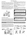
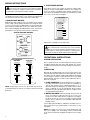
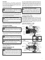
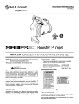
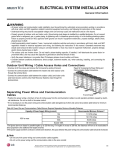
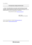
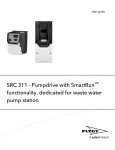
INSTRUCTION MANUAL
P76966E
Booster Pumps
INSTRUCTIONS FOR THE
FOLLOWING B&G PRODUCTS:
21/2", LD3, HD3, PD35, PD37, 1HP & 11/2HP
INSTALLER: PLEASE LEAVE THIS MANUAL FOR THE OWNER’S USE.
DESCRIPTION
For applications requiring higher flow and head pressures, Bell
& Gossett provides an entire range of booster pumps. The
designs of these pumps are based on three-part configuration
which offers complete field repairability and compact construction. All Bell & Gossett boosters are equipped with the
incomparable B&G manufactured motor for quiet and efficient
operation.
SAFETY
INSTRUCTIONS
This safety alert symbol will be used in this manual and on the
pump safety instructions decal to draw attention to safety
related instructions. When used, the safety alert symbol
means ATTENTION! BECOME ALERT! YOUR SAFETY IS
INVOLVED! FAILURE TO FOLLOW THE INSTRUCTIONS MAY
RESULT IN A SAFETY HAZARD.
These pumps are for indoor use only.
WARNING
PUMP APPLICATION
Bell & Gossett Booster Pumps may be used for hydronic heating and cooling systems, domestic water, industrial applications and general service operations. Bell & Gossett recommends that bronze constructed pumps be used for pumping
potable water.
OPERATIONAL LIMITS
V56845
These pumps are designed to pump liquids compatible with
their iron or bronze body construction. This pump line delivers
maximum capacities from 100 GPM to 150 GPM. Unless special provisions have been made by ITT Bell & Gossett, the
operational limits for Series 21/2", LD3, HD3, PD35, PD37,
PD38 & PD40 Pumps are listed below.
Max. Working Pressure:
Max. Operating Temperature:
Electrical Rating:
(1/4 HP only)
BEFORE INSTALLING, USING OR
SERVICING THIS PRODUCT,
READ THE WARNING NOTES
AND INSTRUCTIONS IN
INSTRUCTION MANUAL.
FAILURE TO DO SO MAY
RESULT IN SERIOUS INJURY
OR PROPERTY DAMAGE
125 psi
225°F
115/230V, 60 Hz, 1PH
208-230/460V, 60 Hz, 3PH
115V or 230V, 60 Hz, 1PH
Motors with special electrical characteristics are available on
request. Contact your local Bell & Gossett Representative for
details.
Your Booster Pump should have this warning label affixed to
the pump near the conduit box cover. If this warning is
missing or illegible, contact your local Bell & Gossett
Representative for a replacement.
SAFETY REQUIREMENTS
MECHANICAL SAFETY
ELECTRICAL SAFETY
WARNING: EXCESSIVE SYSTEM PRESSURE
HAZARD
The maximum working pressure of the pump is listed on
the nameplate – DO NOT EXCEED THIS PRESSURE.
Failure to follow these instructions could result in serious
personal injury, death and/or property damage.
WARNING: ELECTRICAL SHOCK HAZARD
Electrical connections are to be made by a qualified
electrician in accordance with all applicable codes, ordinances and good practices. Failure to follow these instructions could result in serious personal injury, death and/or
property damage.
WARNING: EXCESSIVE PRESSURE HAZARD –
VOLUMETRIC EXPANSION
The heating of water and other fluids causes volumetric
expansion. The associated forces may cause failure of system components and the release of high temperature fluids.
This can be prevented by installing properly sized and
located compression tanks and pressure relief valves.
Failure to follow these instructions could result in serious
personal injury, death and/or property damage.
WARNING: ELECTRICAL OVERLOAD HAZARD
Three phase motors must have properly sized
heaters to provide overload and under voltage protection.
Single phase motors have built-in overload protectors.
Failure to follow these instructions could result in serious
personal injury, death and/or property damage.
THERMAL SAFETY
WARNING: EXTREME TEMPERATURE HAZARD
If the pump, motor or piping are operating at extremely
high or low temperature, guarding or insulation is required.
Failure to follow these instructions could result in serious
personal injury, death and/or property damage.
WARNING: ELECTRICAL GROUNDING HAZARD
Adequate electrical grounding is required for the safe
operation of B&G Pumps. The use of grounded metal conduit assures this requirement. If the means of connection to
the supply-connection box (wiring compartment) is other
than grounded metal conduit, ground the pump back to the
service by connecting a copper conductor at least the size
of the circuit conductors supplying the pump to the green
grounding screw provided within the wiring compartment.
Failure to follow these instructions could result in serious
personal injury, death and/or property damage.
WARNING: HOT WATER HAZARD
When disassembling a gasketed joint, always use a
new gasket upon reassembly. NEVER REUSE OLD GASKETS. Failure to follow these instructions could result in
serious personal injury, death and/or property damage.
REMOVAL OF THE PUMP FROM EXISTING SYSTEM FOR REPLACEMENT
WARNING: ELECTRICAL SHOCK HAZARD
Disconnect and lockout the power before servicing.
Failure to follow these instructions could result in serious
personal injury or death.
1. Close the valves on the suction and discharge sides of
the pump. If no valves have been installed, it may be necessary to drain the system.
2. Loosen the conduit box cover screw and remove the cover.
WARNING: UNEXPECTED START-UP HAZARD
Single phase motors are equipped with automatic
reset overload protectors. The pump can restart without
warning. Disconnect and lockout power before servicing.
Failure to follow these instructions could result in serious
personal injury, death and/or property damage.
3. Disconnect the electrical supply lines to the pump.
WARNING: HOT WATER HAZARD
Before draining the system, allow water to cool to
100°F max., open the drain valve (take precautions against
water damage) and leave the drain valve open until servicing is complete. Failure to follow these instructions could
result in serious personal injury, death and/or property
damage.
WARNING: ELECTRICAL SHOCK HAZARD
Be certain the electrical power is not present at the
motor leads before continuing. Failure to follow these instructions could result in serious personal injury or death.
2
WARNING: HIGH PRESSURE HAZARD
Pressure may be present in the pump body. This
pressure can be relieved by loosening the flange bolts and
shifting the pump assembly slightly to allow the pressurized water to escape. Failure to follow these instructions
could result in serious personal injury or death.
4. Remove the flange bolts and nuts and then remove the
pump from the piping.
PUMP INSTALLATION
PUMP LOCATION
Bell & Gossett booster pumps should be installed where there
will be sufficient room for future inspection, maintenance and
service. It is highly recommended that service valves (shut-off)
also be installed on each side of circulator pumps to facilitate
servicing or replacing the pump without draining the system.
If it is required to lift the entire pump, do so with slings placed
around the pump assembly as shown below.
IMPORTANT: In closed systems, do not install and operate
Bell & Gossett pumps, 3D valves, suction diffusers, etc., without properly sized safety and control devices. Such devices
include the properly sized and located pressure relief valves,
compression tanks and pressure, temperature, and flow controls. If the system is not equipped with these devices, consult
the responsible engineer or architect before operating.
TION. THIS MAY RESULT IN UNWANTED STRESS IN THE
PUMP BODY, FLANGE CONNECTIONS AND/OR PIPING. The
code for pressure piping, ANSI B31.1, lists types of supports
for various applications.
Ordinary wire or band hangers are not adequate to maintain
alignment. It is very important to provide strong, rigid support
for the suction and discharge lines.
IMPORTANT: Do not support the pump by its power pack. To
function properly, the power pack must not be restrained.
PUMP FLANGES
New Bell & Gossett flange gaskets must be installed between
the flanges of the pump body and suction and discharge pipes.
The gaskets should be clean and grease-free; old gaskets
should never be reused.
WARNING: HOT WATER HAZARD
When disassembling a gasketed joint, always use a
new gasket upon reassembly. NEVER RE-USE OLD GASKETS. Failure to follow these instructions could result in
serious personal injury, death and/or property damage.
WARNING: HOT WATER HAZARD
Make sure that each flange gasket remains seated in
the flange groove during and after installation. Failure to follow these instructions could result in serious personal
injury, death and/or property damage.
Apply torque in even increments to all (4) flange bolts using a
diagonal tightening pattern to a value of 96-132 in-lbs. (8-11 ft.
lbs.). Both the suction and discharge flanges must be torqued
in this manner.
PUMP SUPPORT AND PIPING
Install the suction and discharge flanges on the pipe ends
using Teflon ® * tape sealer or high quality thread sealant.
Minimize strain on the pump by supporting the suction and discharge piping with pipe hangers near the pump. Line up the
vertical and horizontal pipings so that the bolt-holes in both the
pump and pipe flanges are aligned. DO NOT ATTEMPT TO
SPRING THE SUCTION OR DISCHARGE LINES INTO POSI-
MODE OF DISCHARGE
Bell & Gossett Pumps can be installed to discharge up, down,
left or right. The oiling ports must always be in the twelve
o’clock position (on top) as shown below with the motor and
bearing assembly always in a horizontal position as shown to
the right. THE ARROW ON THE PUMP BODY MUST POINT IN
THE DIRECTION OF THE FLOW. If it becomes necessary to
change the mode of discharge, refer to B&G Instruction Manual
HS-105-SM for specific instructions in removing the motor and
bearing assembly from the pump body.
WARNING: WATER LEAKAGE HAZARD
To prevent leakage, make certain that the flange
bolts have been adequately torqued. Failure to follow these
instructions could result in serious personal injury and/or
property damage.
*Teflon® is a registered trademark of E.I. DuPont de Nemours and Company.
NOTE: The position of the conduit box is determined by the
model of the motor used and must be positioned on the
bottom or the side of the motor housing. As shown to the left.
3
WIRING INSTRUCTIONS
WARNING: ELECTRICAL SHOCK HAZARD
Disconnect and lockout the power before making
electrical connections. Failure to follow these instructions
could result in serious personal injury or death.
Remove the screws securing the conduit box cover (wiring
compartment) and lift off the cover. Attach the appropriate
size connector to the hole in the side of the conduit box.
II. THREE PHASE MOTORS
Three phase motors can operate at either low voltage (208230V) or at high voltage (460V). Determine the voltage you
choose to operate your B&G pump. Wiring instructions for
each option are listed below and are also found in the conduit
box cover or on the motor nameplate.
HIGH VOLTAGE
L1
L2
L3
T1
T2
T3
T4
T7
T5
T8
T6
T9
I. SINGLE PHASE MOTORS
Single phase dual voltage motors can operate at low voltage
(115V) or high voltage (230V). Determine the voltage at which
you choose to operate your B&G pump. Locate the wiring diagram inside the conduit box of the motor. Make the connections as per the diagram provided with the motor. Connect the
ground wire to the ground screw inside the conduit box.
LOW VOLTAGE
T1
T7
T2
T8
T3
T9
T4
T5
T6
SLEEVE BEARING MOTORS
L1
L2
L3
Replace the conduit box cover and screws.
WARNING: ELECTRICAL SHOCK HAZARD
Be certain that all connections are secure and the
conduit box cover is closed before electrical power is connected. Failure to follow these instructions could result in
serious personal injury, death and/or property damage.
OPERATIONAL INSTRUCTIONS
SYSTEM PREPARATION
BALL BEARING
MOTORS
LOW VOLTAGE
5
L2
4
L1
1
BROWN
LOW VOLTAGE
L2
WHITE
1
2
BLACK
L1
6
4
RED
BROWN
BLACK
WHITE
5
6
HIGH VOLTAGE
5
WHITE
L2
4
BLACK
L1
1
6
HIGH VOLTAGE
L2
L1
BROWN
1
2
4
RED
WHITE
BLACK
Prior to pump start up, closed heating and cooling systems
should be flushed with clean water and drained. The system
should then be filled with clean water having a PH between 7
and 9.
LUBRICATION
Although all new B&G pumps are test run at the factory, they
must be lubricated thoroughly before being placed in operation. Bell & Gossett supplies a high quality lubricant specifically
for this purpose which can be purchased from any B&G
Representative (Part No. L23401). Proper lubrication procedures are as follows:
5
6
BROWN
NOTE: Single phase motors are protected with inherent
overheating devices and do not require external overload
protection.
1. PUMP BEARINGS: Fill the bearing frame according to
the oiling instructions decal. At the time of installation or
start of each heating season, add approximately 1 oz. of
B&G #20 weight non-detergent oil. A SAE 20 (non-detergent) or 10W-30 oil may be substituted. More frequent
lubrication may be required under adverse conditions such
as high ambient temperatures.
2. MOTOR BEARINGS: Lubricate through the two motor oil
ports according to lubrication decal once every four
months (more often under adverse conditions). Use eight to
ten drops in each oil cup. Does not apply to PD38 & PD40
pumps. These models use permanently lubricated ball
bearing motors.
For non-Bell & Gossett Motors, lubrication should be in accordance with the motor manufacturer's instructions on the
nameplate.
NOTE: Over-oiling can cause motor mount deterioration and
may cause spillage onto surrounding surfaces. Deteriorated
motor mounts will lead to misalignment and excessive coupler
wear.
4
ROTATION
21/2",
Pump rotation for the
LD3 and HD3 is counterclockwise
when viewed from the back of the motor. Whereas the rotation is clockwise when views from the back of the motor for
the PD35, PD37, PD38, and PD40 pumps. An arrow is provided to show the rotational direction.
The system should be drained by opening the boiler drain valve
and the vent near the top of the system. If a Flo-Control valve
is installed and there are balance valves on the returns, then
the balance valves may be closed to isolate the boiler from the
system. The Flo-Control valve will act as a check valve on the
supply and only the boiler will need to be drained. Open a vent
between the boiler and the system.
PRIMING AND STARTING
CAUTION: SEAL DAMAGE HAZARD
Do not run the pump dry – seal damage may occur.
Failure to follow these instructions could result in moderate
personal injury and/or property damage.
WARNING: HIGH PRESSURE HAZARD
Pressure may be present in the pump body. This
pressure can be relieved by loosening the volute capscrews and shifting the bearing assembly slightly to allow
the pressurized water to escape. Failure to follow these
instructions could result in serious personal injury or death.
Do not run B&G circulator pumps dry. Before starting, the
pump must be filled with water. Air should be vented from the
system by means of a system air vent at a high point in the
system or by an alternate method. The system must be completely vented prior to pump operation.
Separate the bearing assembly and motor from the pump body
by removing the volute capscrews from the bearing bracket or
cover plate (see diagrams at right).
DETERMINE THE SEAL TYPE
WARNING: HOT WATER LEAKAGE HAZARD
Pressurize the pump body slowly while checking for
leaks at all joints with gaskets. Failure to follow these
instructions could result in serious personal injury and/or
property damage.
The pump should be started with the discharge valve closed
and the suction valve fully open. After the pump is at operating speed, the discharge valve should be opened gradually.
Cut away diagrams have been provided to illustrate the components of the booster bearing assemblies. The primary feature
distinguishing the mechanical seals of the 21/2", LD3, HD3,
PD35, and PD37 pumps from the PD38 and PD40 is the shape
of the spring retainer which is seated between the spring and
the impeller. Refer to the following diagrams whenever seal
replacement becomes necessary.
PUMP BODY DIAGRAM – 1/2" SEAL
Series 21/2", LD3, HD3, PD35, PD37
Discharge Gage Tapping
(on side opposite)
REPLACING THE SEAL
DISCONNECT THE ELECTRICAL SUPPLY
WARNING: ELECTRICAL SHOCK HAZARD
Disconnect and lockout the power before servicing.
Failure to follow these instructions could result in serious
personal injury or death.
9 Seal Assembly
10 Volute Gasket
Coupler Assembly
3 Impeller (Enclosed)
8 Shaft Sleeve
4 Impeller Key
6 Impeller Lock Nut
7 Pump Shaft
1 Volute
5 Impeller Lock Washer
The electrical supply must be turned off and the pump service
valves must be closed before servicing procedures begin. If
no service valves are installed, the city water supply valve
should be closed.
Motor Bracket
Assembly
Bearing Bracket
Assembly
2 Face Plate
Rear Bearing
Front Bearing
Volute Capscrews
12 Companion Flange
(included)
Suction Gage
Tapping
WARNING: ELECTRICAL SHOCK HAZARD
Be certain the electrical power is not present at the
motor leads before continuing. Failure to follow these
instructions could result in serious personal injury or death.
WARNING: UNEXPECTED START-UP HAZARD
Disconnect and lockout power before servicing.
Failure to follow these instructions could result in serious
personal injury, death and/or property damage.
9A Seal Housing
9E Seat Insert
9F Seat Gasket
PUMP BODY DIAGRAM –
SEAL
Series PD38, PD40
3/4"
Discharge Gage Tapping
(on side opposite)
Coupler Assembly
Loosen the conduit box cover screws and remove the cover.
Follow this procedure with the removal of the wire nuts and
flexible conduit connector.
10 Volute Gasket
Rear Bearing Lip Seal
9D Spring
9C Seal Ring
Mechanical Seal
9 Seal Assembly
3 Impeller (Enclosed)
4 Impeller Key
7 Pump Shaft
6 Impeller Lock Nut
REMOVE THE MOTOR AND
BEARING ASSEMBLY
WARNING: HOT WATER HAZARD
Before draining the system, allow water to cool to
100ºF max., open the drain valve (take precautions against
water damage) and leave the drain valve open until servicing is complete. Failure to follow these instructions could
result in serious personal injury, death and/or property
damage.
9B Bellows
5 Impeller Lock Washer
Motor Bracket
Assembly
Bearing Bracket
Assembly
Front Bearing
Volute Capscrews
11 Cover Plate
Suction Gage Tapping
1 Volute
8 Shaft Sleeve
12 Companion Flange
(included)
except 2-1/2"
5
REPLACEMENT PROCEDURE
With the bearing assembly and motor removed from the system, use the following instructions to facilitate the replacement.
1. Use a strap wrench or rag to prevent the impeller from
turning with one hand and loosen the impeller nut with the
other.
2. Lift the spring retainer and the seal spring from the shaft.
Remove the compression ring from the seal collar by
inserting a small screwdriver underneath the ring and
carefully applying an upward prying force. Remove the
ring, collar and the remaining seal components from the
shaft.
NOTE: Bell & Gossett seal assemblies consist of an insert
retainer, rubber gasket, ceramic insert, carbon seal ring, rubber collar, brass collar and compression ring, spring and
spring retainer. Each of these components must be replaced
when replacing the mechanical seal. NEVER REPLACE INDIVIDUAL COMPONENTS SEPARATELY.
3. Using a clean, lint free rag, remove any debris that may
have accumulated in the seal recess.
4. Place the new retainer in the bearing assembly's seal
recess. Seat the thin rubber gasket in the recess and set
the ceramic insert atop the gasket. The ceramic has a top
side and bottom side. The bottom is identifiable by its
slightly recessed grooves. These grooves should face
downward toward the rubber gasket.
5. Before proceeding, place the shaft end on a wooden
block; the wooden block should push the shaft to its forward-most position (there should not be any end-play in
the shaft).
6. Lubricate the rubber seal collar with soapy water. The
entire rotating seal assembly, which includes the carbon
seal ring, rubber collar, brass collar and compression ring,
is to be pushed onto the shaft as one unit. Do not attempt
to assemble the seal by placing the components on the
shaft individually. The notches in the brass collar should
be aligned with the recesses found on each side of the
carbon ring.
7. Press the brass compression ring tightly against the
upper end of the rubber collar. A screwdriver can be used
at several points along its periphery to provide a tight and
even fit. Press with the screwdriver – do not tap. Tapping
on the seal may break the ceramic or carbon insert.
8. With the shaft resting on the wooden block, place the
seal spring and spring retainer on the shaft. Next, place
the impeller and lock washer. Thread the impeller nut to
the shaft and tighten to 96-144 in.-lbs. (8-12 ft. lbs.). Do
not overtighten.
WARNING: HOT WATER HAZARD
Whenever the bearing assembly is removed from the
piping, use a new gasket when re-installing. Failure to follow these instructions could result in serious personal
injury and/or property damage.
9. Clean the pump body of excess debris. Place a new gasket in the recess of the pump body; ensure that it sits
flush against the gasket surface.
10. Replace the motor and bearing assembly by inserting the
impeller in the pump body and evenly tightening the capscrews to 156 in.-lbs. (13 ft. lbs.) using a diagonal tightening pattern.
11. Refer to the WIRING INSTRUCTIONS section in this manual
to properly configure all electrical connections.
12. Following the OPERATIONAL INSTRUCTIONS section in
this manual to 1) check the PH of the system water, 2) to
check the rotation of the pump, and 3) to prime the system prior to starting.
GENERAL INSTRUCTIONS
ADDITIONAL PUMP REPAIR
1. Keep the pump and motor properly lubricated.
Refer to the following manual for further repair instructions for
the Bell & Gossett Pumps:
2. If the system is to be exposed to freezing temperatures,
drain the pump.
PERIODIC INSPECTION
Coupler & Motor Mount Replacement . . . . .#P06452
. . . . . . . . . . . . . . . . . . . . . . . . . . . . ooooor #S15900 Rev. D
Booster Pump Service Manual . . . . . . .#HS-105-SM, Rev. 3
Inspect the pump for leaking seals, worn gaskets, and looses
or damaged components. Replace or repair as required.
DEALER SERVICING
YOUR BELL & GOSSETT REPRESENTATIVE IS...
If your pump requires further repair, contact your local B&G
Representative. Having the following information at hand will
facilitate your representative's ability to assist you:
1. Complete data from nameplate.
2. Suction and discharge pipe pressure gauge readings.
3. Ampere draw of the motor.
4. A sketch of the pumping system (includes pipes, valves, etc.)
Xylem Inc.
8200 N. Austin Avenue
Morton Grove, Illinois 60053
Phone: (847) 966-3700
Fax: (847) 965-8379
www.xyleminc.com/brands/bellgossett
Bell & Gossett is a trademark of Xylem Inc. or one of its subsidiaries.
© 2012 Xylem Inc. P76966E April 2012