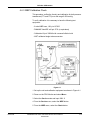
1
PRO Series 100 - 400 V2 Service Manual (Models 110 - 410) DINAMAP® PRO Series 100-400V2 Monitor Service Manual NOTE The Model Numbers 100 through 400 are generic in nature and reflect the range of product codes available. Your product may be labeled with a specific product code such as DINAMAP® PRO Model 410. “V2” refers to the second version of the product’s design. 2018553-001 Revision B DINAMAP® PRO Series 100-400V2 Monitor Service Manual 2018553-001 Revision B DINAMAP® Series PRO 100-400V2 Monitor Service Manual This manual is for DINAMAP PRO Series Monitor models 100, 200, 300, and 400, with or without printers. • PRO 100: BP, Pulse • PRO 200: BP, Pulse, and Temp • PRO 300: BP, Pulse, and SpO2 • PRO 400: BP, Pulse, Temp, and SpO2 The model of the Monitor determines which parameters are in your monitor. Please refer to applicable sections. Reissues and Updates Changes occurring between issues are addressed through Change Information Sheets, Addendums, and replacement pages. If a Change Information Sheet does not accompany this manual, it is correct as printed. Errors and Omissions If errors or omissions are found in this manual, please notify: GE Medical Systems Information Technologies, Inc. 8200 West Tower Avenue Milwaukee, WI 53223 USA Tel: +414.355.5000 800.558.5120 (US only) Fax:+414.355.3790 Part No. 2018553-001 B The content of this document including all figures and drawings is proprietary information of GE Medical Systems Information Technologies, provided solely for purposes of operation, maintenance or repair, and dissemination for other purposes or copying thereof is prohibited without prior written consent by GE Medical Systems Information Technologies. Illustrations may show design models; production units may incorporate changes. Hierarchy of Warnings and Cautions A general warning is a statement that alerts the user to the possibility of injury, death, or other serious adverse reactions associated with the misuse of the device. A warning relates to steps in a procedure. A general caution is a statement that alerts the user to the possibility of a problem with the device associated with its use or misuse. Such problems include device malfunction, device failure, damage to the device or damage to other property. A caution relates to steps in a procedure. © Copyright 2004, GE Medical Systems Information Technologies. All rights reserved. Revision B DINAMAP® PRO Series 100-400V2 Monitor Service Manual 2018553-001 World Headquarters GE Medical Systems Information Technologies, Inc. 8200 West Tower Avenue Milwaukee, WI 53223 USA Tel: +414.355.5000 800.558.5120 (US only) Fax:+414.355.3790 European Representative GE Medical Systems Information Technologies GmbH Munzinger Straße 3-5 D-79111 Freiburg Germany Tel: + 49 761 45 43 - 0 Fax: + 49 761 45 43 - 233 Asia Headquarters GE Medical Systems Information Technologies Asia; GE (China) Co., Ltd. 24th Floor, Shanghai MAXDO Center, 8 Xing Yi Road, Hong Qiao Development Zone Shanghai 200336, P.R. China Tel: + 86 21 5257 4650 Fax: + 86 21 5208 2008 DINAMAP® PRO Series 100-400V2 Monitor Service Manual 2018553-001 Revision B Table of Contents TABLE OF CONTENTS Section 1. INTRODUCTION 1.1 SCOPE OF MANUAL ......................................................................... 1-3 1.2 ADDENDA .......................................................................................... 1-4 1.3 TRADEMARKS AND TRADE NAMES ............................................... 1-4 1.4 SERVICE POLICY .............................................................................. 1-4 1.5 EXTENDED WARRANTIES ............................................................... 1-4 1.6 ASSISTANCE ..................................................................................... 1-4 1.7 SERVICE ............................................................................................ 1-5 1.7.1 Packing Instructions ............................................................. 1-5 1.7.2 Insurance ............................................................................. 1-5 1.7.3 Replacement Assemblies and Components ........................ 1-5 1.7.4 Replacement Accessories ................................................... 1-6 1.8 INSTALLATION AND OPERATION ................................................... 1-6 1.9 WARNINGS AND PRECAUTIONS .................................................... 1-6 1.10 DISPOSAL OF PRODUCT WASTE ................................................. 1-6 1.10.1 Batteries ............................................................................. 1-6 1.10.2 Patient Applied Parts ......................................................... 1-7 1.10.3 Packaging Material ............................................................ 1-7 1.10.4 Monitor ............................................................................... 1-7 1.11 SYMBOL DEFINITIONS ................................................................... 1-8 1.12 GLOSSARY OF TERMS AND ABBREVIATIONS ............................ 1-9 Section 2. PRODUCT DESCRIPTION 2.1 INTRODUCTION ................................................................................ 2-3 2.2 PRODUCT CONFIGURATIONS ........................................................ 2-3 2.3 CONTROLS, INDICATORS, AND CONNECTORS ........................... 2-3 3.1 PRO Series Monitor Rear Panel Connections ........................ 2-4 2.3.2 Front Panel Controls and Indicators .................................... 2-5 2.4 HOST PORT CONNECTOR (REAR PANEL) .................................... 2-7 2.5 REORDER PART NUMBERS ............................................................ 2-8 2.6 SPECIFICATIONS ............................................................................ 2-10 Revision B DINAMAP® PRO Series 100-400V2 Monitor Service Manual 2018553-001 Table of Contents Section 3. THEORY OF OPERATION 3.1 INTRODUCTION ................................................................................ 3-3 3.2 OVERALL PRINCIPLES OF OPERATION ........................................ 3-3 3.2.1 Cuff Blood Pressure (BP) and Pulse ................................... 3-3 3.2.2 Temperature (Model 200 and 400) ...................................... 3-4 3.2.3 SpO2 (Model 300 and 400) ................................................. 3-4 3.2.4 Host Communication Port .................................................... 3-4 3.3 FUNCTIONAL DESCRIPTION ........................................................... 3-5 3.3.1 PSU PWA ............................................................................ 3-5 3.3.2 PSU Module ......................................................................... 3-5 3.3.3 Main Board .......................................................................... 3-5 3.3.4 SpO2 PWA (Optional) .......................................................... 3-6 3.3.5 Pneumatic Control Device ................................................... 3-7 3.3.6 LCD Assembly ..................................................................... 3-7 3.3.7 Printer PWA w/Printer .......................................................... 3-7 Section 4. GENERAL MAINTENANCE 4.1 INTRODUCTION ................................................................................ 4-3 4.2 FUSES ................................................................................................ 4-3 4.3 PERIODIC MAINTENANCE ............................................................... 4-3 4.3.1 Cleaning the Monitor ............................................................ 4-3 4.3.2 Power-Up Checks ................................................................ 4-4 4.3.3 External DC Supply and Battery .......................................... 4-5 4.3.4 Care of the Storage Battery ................................................. 4-5 4.3.5 Checking Calibration ............................................................ 4-6 4.4 CLINICIAN MODE ............................................................................... 4-6 4.4.1 Accessing the Clinician Mode .............................................. 4-6 4.4.2 Clinician Mode Main Menu .................................................. 4-7 4.4.3 Clinician More... Menu ......................................................... 4-8 4.5 SERVICE MODE .............................................................................. 4-10 4.5.1 Accessing the Service Mode ............................................. 4-10 4.5.2 Service Mode Main Menu .................................................. 4-11 4.5.3 NIBP Menu ........................................................................ 4-12 4.5.4 System Menu ..................................................................... 4-14 DINAMAP® PRO Series 100-400V2 Monitor Service Manual 2018553-001 Revision B Table of Contents 4.6 PRE-SERVICE TEST PROCEDURES ............................................. 4-16 4.6.1 SpO2 Checks (PRO 300 & 400) ........................................ 4-16 4.6.2 Leak Test ........................................................................... 4-18 4.6.3 NIBP Calibration Check ..................................................... 4-19 4.6.4 Neonate Overpressure Check ........................................... 4-20 4.6.5 Adult Overpressure Check ................................................. 4-20 4.6.6 Temperature System Check (PRO 200 & 400) ................. 4-21 4.6.7 Printer Test ........................................................................ 4-22 4.7 PRO MONITOR CALIBRATION PROCEDURES ............................ 4-22 4.7.1 Calibrating the NIBP Transducer ....................................... 4-22 4.7.2 Overpressure Adjustment of a Two-Pot System ................ 4-23 4.8 ELECTRICAL SYSTEM SAFETY CHECKS ..................................... 4-25 4.9 FEATURES SELECTION .................................................................. 4-25 4.10 TROUBLESHOOTING .................................................................... 4-27 4.11 ERROR CODES.............................................................................. 4-29 Appendix A: Test Records Appendix B: Field Replaceable Parts and Assembly Drawings Appendix C: Electromagnetic Compatibility Revision B DINAMAP® PRO Series 100-400V2 Monitor Service Manual 2018553-001 Table of Contents DINAMAP® PRO Series 100-400V2 Monitor Service Manual 2018553-001 Revision B 1 Revision B Introduction DINAMAP® PRO Series 100-400V2 Monitor Service Manual 2018553-001 1-1 1-2 DINAMAP® PRO Series 100-400V2 Monitor Service Manual 2018553-001 Revision B Introduction Section 1. INTRODUCTION 1.1 SCOPE OF MANUAL This service manual provides service, parts, and repair information and functional descriptions for the DINAMAP® PRO Series Monitors, Models 100, 200, 300, and 400. The model number identifies the vital signs monitoring capabilities built into the unit. PRO 100: BP, pulse PRO 200: BP, pulse, temperature PRO 300: BP, pulse, SpO2 PRO 400: BP, pulse, temperature, SpO2 This manual is intended for use by biomedical engineers and trained service technicians who are familiar with electromechanical devices and digital and analog circuit techniques. WARNINGS: To reduce the risk of electric shock, do not open the case. No user-serviceable parts are inside the case. Refer servicing to qualified service personnel. Trained service technicians should perform all unit repairs. Voltages dangerous to life exist in this unit. Take care when servicing power supply and display assembly. For information about operating PRO Series Monitors in a clinical environment, refer to the separate operation manual. This service manual is composed of the following five sections: Revision B Section 1 describes this manual and tells you how to use it. Information is also provided about how to get assistance if the unit fails to function properly. Section 2 provides the physical and functional characteristics of the PRO Series Monitor. Section 3 explains the principles of operation for the PRO Series Monitor, including an overall system description and principles of operation at the PWA (printed wiring board) level. Section 4 provides information about periodic and corrective maintenance of the PRO Series Monitor. Procedures include calibration checks, recalibration, performance tests, and fault isolation. Section 5 provides component information about the PRO Series Monitor, including disassembly procedures, parts lists, assembly diagrams, and electrical schematics. DINAMAP® PRO Series 100-400V2 Monitor Service Manual 2018553-001 1-3 Introduction 1.2 ADDENDA When this manual was published it included the most up-to-date information and procedures available. However, the specifications, design, assembly, or software controls may change. These changes are incorporated into this manual by addenda. 1.3 TRADEMARKS AND TRADE NAMES This document references terms that are proprietary, and may be registered and protected by copyrights and other applicable laws and agreements. The first time trademarks and trade names are used in a section of this document, they are followed by “*” or “**”. A footnote will identify the owner of the trademark or trade name. 1.4 SERVICE POLICY The warranty for this product is enclosed with the product in the shipper carton. All repairs on products under warranty must be performed or approved by Customer Support personnel. Unauthorized repairs will void the warranty. Products not covered by warranty should be repaired by qualified electronics service personnel. 1.5 EXTENDED WARRANTIES Extended warranties may be purchased on most products. Contact your Sales Representative for details and pricing. 1.6 ASSISTANCE If the product fails to function properly or if assistance, service, or spare parts are required, contact Customer Support. Before contacting Customer Support, it is helpful to attempt to duplicate the problem and to check all accessories to ensure that they are not the cause of the problem. If you are unable to resolve the problem after checking these items, contact Customer Support. When you call, please be prepared to provide: Product name and model number A complete description of the problem If repair parts or service are necessary, you will also be asked to provide: 1-4 The product serial number The facility's complete name and address DINAMAP® PRO Series 100-400V2 Monitor Service Manual 2018553-001 Revision B Introduction A purchase order number if the product is to be sent for repairs or you order spare parts The facility's GE Medical Systems Information Technologies account number, if possible The part number for replacement assemblies or parts 1.7 SERVICE If your product requires repair service, call Customer Support and a representative will assist you. Prior to returning any product for repair, you must request a Return Authorization number. Call GE Medical Systems Information Technologies at: 1-877-274-8456 Monday through Friday, 8:00 a.m. to 6:00 p.m. EST, excluding holidays. 1.7.1 Packing Instructions Follow these recommended packing instructions. Remove the battery and all hoses, cables, sensors, and power cords from the PRO Series Monitor before packing. Pack only the accessories you are requested to return. Place them in a separate bag and insert the bag and the product inside the shipping carton. Use the original shipping carton and packing materials, if available. If the original shipping carton is not available, place the product in a plastic bag and tie or tape the bag to prevent loose particles or materials from entering openings such as the hose ports. Use a sturdy corrugated container to ship the product; tape securely to seal the container for shipping. Pack with 4 in. to 6 in. of padding on all sides of the product. 1.7.2 Insurance Insurance is at the customer's discretion. Claims for damage to the product must be directed to the shipper. 1.7.3 Replacement Assemblies and Components Assemblies and components can be ordered from GE Medical Systems Information Technologies: Via phone: 1-800-558-7044, Option #2 Via FAX: 1-800-232-2599 Information is also available on the World Wide Web at: http://www.gemedical.com Revision B DINAMAP® PRO Series 100-400V2 Monitor Service Manual 2018553-001 1-5 Introduction All orders must include the following information: Facility's complete name, address, and phone number FAX number Your purchase order number Your GE Medical Systems Information Technologies account number Please allow one working day for confirmation of your order. 1.7.4 Replacement Accessories Replacements such as hoses, sensors, etc. must be purchased from GE Medical Systems Information Technologies at 1-800-558-5102 (fax 1-800-232-2599). Please have the Reorder/Product Code or part number of the item you wish to order, and your purchase order and account number available. 1.8 INSTALLATION AND OPERATION For information on the installation and operation of the PRO Series Monitor, refer to the separate operation manual. The PRO Series Monitor should be operated and serviced by authorized personnel, and only in accordance with the warnings and precautions given in both the operation manual and this service manual. 1.9 WARNINGS AND PRECAUTIONS Refer to the operating safety warnings and precautions detailed in the separate operation manual. 1.10 DISPOSAL OF PRODUCT WASTE As you use the PRO Monitor, you will accumulate solid wastes that require proper disposal or recycling. These include batteries, patient applied parts, and packaging material. 1.10.1 Batteries Caution: Do not incinerate batteries. The sealed, rechargeable backup battery contains lead and can be recycled. The rechargeable memory battery is of the Nickel Metal Hydride form. Discharge this battery prior to disposal. Place the battery in packaging which electrically isolates its contents. Do not puncture or place the battery in a trash compactor. Do not incinerate the battery or expose it to fire or high temperatures. Dispose in accordance with regional body controlled guideline. 1-6 DINAMAP® PRO Series 100-400V2 Monitor Service Manual 2018553-001 Revision B Introduction 1.10.2 Patient Applied Parts Certain patient applied parts, such as those with adhesive (disposable SpO2 sensors), are intended for single use and should be disposed of properly as medical waste in accordance with regional body controlled guideline. Other patient applied parts, such as blood pressure cuffs, should be cleaned according to instructions. Inspect reusable applied parts for wear, replace as necessary, and dispose of used product as medical waste in accordance with regional body controlled guideline. 1.10.3 Packaging Material Retain original packaging materials for future use in storing or shipping the Monitor and accessories. This recommendation includes corrugated shippers and inserts. Whenever possible recycle the packaging of accessories and patient applied parts. 1.10.4 Monitor At the end of its service life, the product described in this manual, as well as its accessories, must be disposed of in compliance with the guidelines regulating the disposal of such products. If you have questions concerning disposal of the product, please contact GE Medical Systems Information Technologies or its representatives. Revision B DINAMAP® PRO Series 100-400V2 Monitor Service Manual 2018553-001 1-7 Introduction 1.11 SYMBOL DEFINITIONS Attention: consult accompanying documents Power ON/OFF SILENCE START/STOP BP AUTO BP Mean Arterial Pressure (MAP) External Communications Port Connector Defibrillator-proof Type B.F. equipment SpO2 Temperature Beats Per Minute (BPM) BPM Battery Power External AC or DC Power Indicator External DC Power Input External AC Power Input SpO2 Motion Artifact (US) SpO2 Motion Artifact (Europe) Packaging label depicting the transportation and storage atmospheric pressure range of 500 to 1060 hPa. IPX1 1-8 The DINAMAP® PRO Series Monitor is protected against vertically falling drops of water and conforms with the IEC 529 standard at level of IPX1. Vertically falling drops of water shall have no harmful effects to the Monitor. DINAMAP® PRO Series 100-400V2 Monitor Service Manual 2018553-001 Revision B Introduction 1.12 GLOSSARY OF TERMS AND ABBREVIATIONS AC ADC Analog to Digital Convertor ADU Analog to Digital Units: The Main Board has 65,536 steps which equates to 5V full scale (76 µV/ADU) Secondary Processor ADC has 256 steps which equates to 5V full scale (19.351 mV/ADU) AM ASSY BP BPM DC Amplitude Modulation Assembly Blood Pressure Beats Per Minute Direct Current DMM Digital Multimeter FET Field Effect Transistor GAL Gate Array logic mb mmHg HCD Hz Revision B Alternating Current Millibar Millimeters of Mercury Host Communications Device Hertz LCD Liquid Crystal Display LED Light Emitting Diode MAP Mean Arterial Pressure NIBP Non Invasive Blood Pressure NiMh Nickel Metal Hydride OSC Oscillatory PSU Power Supply Unit PWA Printed Wiring Assembly SPI Serial Peripheral Interface TTL Transistor to Transistor Logic UUT Unit Under Test VAC Volts Alternating Current VDC Volts Direct Current VFC Voltage to Frequency Convertor DINAMAP® PRO Series 100-400V2 Monitor Service Manual 2018553-001 1-9 Introduction 1-10 DINAMAP® PRO Series 100-400V2 Monitor Service Manual 2018553-001 Revision B 2 Revision B Product Description DINAMAP® PRO Series 100-400V2 Monitor Service Manual 2018553-001 2-1 2-2 DINAMAP® PRO Series 100-400V2 Monitor Service Manual 2018553-001 Revision B Product Description SECTION 2. PRODUCT DESCRIPTION 2.1 INTRODUCTION DINAMAP® PRO Series 100-400 Monitors provide non-invasive determination of systolic blood pressure, diastolic blood pressure, mean arterial pressure, pulse rate, temperature, and oxygen saturation. These portable AC and DC operated monitors are primarily intended for use in hospital acute care settings such as outpatient surgery, accident and emergency, labor and delivery, GI/ endoscopy, and medical/surgical units. 2.2 PRODUCT CONFIGURATIONS Each PRO Series Monitor is supplied with an accessory pack. The contents of the pack vary according to model. Unpack the items carefully, and check them against the contents checklist enclosed in one of the accessory boxes. If there is a problem or shortage, contact GE Medical Systems Information Technologies. It is recommended that all the packaging be retained, in case the PRO Series Monitor must be returned for service in the future. 2.3 CONTROLS, INDICATORS, AND CONNECTORS Descriptions of the items shown are listed on the pages that follow. For symbol definitions, refer to Section 1 of this manual. Revision B DINAMAP® PRO Series 100-400V2 Monitor Service Manual 2018553-001 2-3 Product Description 2.3.1 PRO Series Monitor Rear Panel Connections 1. Battery compartment cover: Retains and protects the internal battery. 2. Mains input: Used to connect to AC power supply. 3. External power socket: To be used with approved AC-DC power converter ONLY. 4. Inactive temperature cable storage: Inactive temperature probe cable attaches here (Models 200 and 400). 5. Pole clamp: Used to clamp monitor to pole or stand. 6. Data interface connector: Host communications port (15 way Dtype RS-232 serial port) for use only with equipment conforming to IEC 601-1. Refer to section 2.4 for connection details. 2-4 DINAMAP® PRO Series 100-400V2 Monitor Service Manual 2018553-001 Revision B Product Description 2.3.2 Front Panel Controls and Indicators 7. Systolic pressure display: 3-digit red LED indicates measured systolic BP in mmHg. 8. Active temperature probe holster: Temperature probe that is being used stored here (Models 200 and 400). 9. Diastolic pressure display: 3-digit red LED indicates measured diastolic BP in mmHg. 10. Temperature probe cover storage: Box of probe covers stored here (Models 200 and 400). 11. Inactive temperature probe holster: Extra temperature probe stored here (Models 200 and 400). 12. Temperature display: 4-digit red LED indicates measured temperature (Models 200 and 400). 13. °C °F display: Indicates whether temperature is being displayed in degrees Celsius or Fahrenheit (Models 200 and 400). 14. External power indicator: Green LED indicates external power status and battery charging status of PRO Series Monitor. 15. Temperature probe connector: Temperature probe cable attaches here (Models 200 and 400). Revision B DINAMAP® PRO Series 100-400V2 Monitor Service Manual 2018553-001 2-5 Product Description 16. ON/OFF switch: Controls on/off state of PRO Monitor; push for power on and push again for power off. 17. Battery power indicator: Yellow LED indicates operation and charge status of battery. 18. SpO2 sensor connector: SpO2 sensor extension cable attaches here (Models 300 and 400). 19. Mean arterial pressure display: 3-digit red LED indicates measured MAP in mmHg and shows instantaneous cuff pressure during BP determination. 20. SpO2 pulse indicator: Yellow LED in heart symbol flashes to indicate that real-time pulse rate measurements are being derived from SpO2 signals (Models 300 and 400). 21. Rotor: Used to highlight and select items in LCD menus; if monitor is off, pressing rotor will switch monitor on. 22. Pulse BPM display: 3-digit yellow LED shows pulse rate in beats per minute. 23. SpO2 display: 3-digit red LED indicates oxygen saturation in % (Models 300 and 400). 24. SpO2 motion/artifact indicator LED: For NELLCOR, LED Illuminates when motion artifact is detected (Models 300 and 400). For Masimo, LED illuminates when low perfusion or low signal quality is detected (Models 300 and 400). 25. LCD (liquid crystal display): Displays all alarms, user interface messages, and configuration options. 26. Alarm silence switch: Alternately mutes and enables audible alarms; when pushed once after alarm sounds (silence on), the switch illuminates to indicate that audible alarms have been silenced for 2 minutes. 27. AUTO BP key: Press to start Auto BP mode. 28. Light sensor: Automatically measures ambient light to set LED display intensity. 29. START/STOP BP key: Press to start or stop a BP, Auto, Stat, or Vitals determination. 30. Cuff connector: BP cuff hose attaches here. Not Shown: The printer access door is located on the left side of the monitor. Push the latch to open the door and access the paper supply and print head. 2-6 DINAMAP® PRO Series 100-400V2 Monitor Service Manual 2018553-001 Revision B Product Description 2.4 HOST PORT CONNECTOR (REAR PANEL) WARNING! Auxiliary equipment connected to the DINAMAP® PRO Series Monitor will result in the formation of an electromedical system and thus, must comply with the requirements of EN 60601-1-1/ IEC 601-1. All host port signals are NON-ISOLATED and should be connected to equipment conforming to IEC-601-1, configured to comply with IEC 601-1-1 ONLY. Where isolation of data communication is required, GE Medical Systems Information Technologies part number ILC1926 and 683235 (Cable Assembly) should be used. If external alarm control is required, GE Medical Systems Information Technologies part number 487208CR (Isolated Remote Alarm Cable Assembly) should ALWAYS be used. Please refer to the Information Sheet included with the isolated remote alarm cable for details. Note: When using remote alarm, the PRO Series Monitor should be considered the primary alarm source. The secondary alarm is used for secondary purposes only. Pin Assignments Revision B Pin Function 1 Ground 2 Inverted TTL Transmit Data 3 Inverted TTL Receive Data 4 Fused +5 Volts 5 No connection 6 No connection 7 Ground 8 Remote Alarm 9 RS232 Request to Send (RTS) 10 RS232 Clear to Send (CTS) 11 RS232 Transmit Data (TxD) 12 No connection 13 RS232 Receive Data (RxD) 14 No connection 15 No connection DINAMAP® PRO Series 100-400V2 Monitor Service Manual 2018553-001 2-7 Product Description 2.5 REORDER PART NUMBERS Product Product Code DINAMAP PRO Monitor Operations Manual-English 2018548-001 DINAMAP PRO Monitor Service Manual-English 2018553-001 Battery, 12V Lead Acid 633132 Printer Paper (box of 10) 089100 DINAMAP Rolling Stand 003215 NIBP: Air Hose 12 ft Adult/Pediatric, Screw Connector 107365 Air Hose 24 ft Adult/Pediatric, Screw Connector 107366 Air Hose 12 ft Neonatal 107368 Air Hose 12 ft Adult/Pediatric, Quick Disconnect 88847 CUFF Assortment Packs: CLASSIC-CUF® Assortment Pack: 2692 Includes: 1 each: Infant, Child Small ADult, Adult, Large Adult, Thigh Cuff CLASSIC-CUF® Assortment Pack, Neonate: 2693 Includes: 2 Neo #1, 3 Neo #2, 5 Neo #3, 5 Neo #4, 5 Neo #5 SOFT-CUF® Assortment Pack: 2695 Includes: 1 Infant, 1 Child, 2 Small Adult, 2 Adult, 2 Large Adult, 1 Thigh, 1 Adult Long SOFT-CUF® Assortment, Neonate: 2694 Includes: 2 Neo #1, 3 Neo #2, 5 Neo #3, 5 Neo #4, 5 Neo #5 DURA-CUF® Assortment Pack: 2699 Includes: 1 each: Infant, Child, Small Adult, Adult, Large ADult, Thigh Cuff DURA-CUF® Assortment Pack, Adult: 2698 Includes: 1 each: Infant, Child, Small Adult, Adult, Large Adult, Thigh Cuff SENSA-CUFTM Assortment Pack, 2-Tube Screw Connectors: 2697 Includes: 1 each: Small Adult, Adult, Large Adult, NIBP Calibration Kit 320246 Additional Blood Pressure Cuff Codes are available through: http://www.gemedical.com 2-8 DINAMAP® PRO Series 100-400V2 Monitor Service Manual 2018553-001 Revision B Product Description Product Product Code TEMPERATURE IVAC® TURBO TEMP Kit (contains 615118 & 2008774-001) 2011530-001 IVAC® TURBO TEMP Oral Temp Probe, Long Cord 2008774-001 IVAC® TURBO TEMP Rectal Temp Probe, Long Cord 2008775-001 IVAC® Temperature Probe Covers 088015 IVAC is a trademark of ALARIS Medical Systems SpO2: NELLCOR®: Pulse Oximeter Cable DOC-10 2008773-001 DuraSensor Adult Oxygen Sensor 407705-006 NELLCOR is a trademark of Nellcor Puritan Bennett Masimo®: Masimo® SpO2 Kit (contains 2009745-001 & 2009743-001) 2011605-001 Adult Reusable Sensor, 1/BX (NR125) 2009745-001 Cable (PC08) 2009743-001 Masimo SET® is a trademark of Masimo Corporation Revision B DINAMAP® PRO Series 100-400V2 Monitor Service Manual 2018553-001 2-9 Product Description 2.6 SPECIFICATIONS This product conforms to the essential requirements of the Medical Device Directive. Accessories without the CE Mark are not guaranteed to meet the Essential requirements of the Medical Device Directive. IPX1 The PRO Series Monitor is protected against vertically falling drops of water and conforms to the IEC 529 standard at level of IPX1. Vertically falling drops of water shall have no harmful effects to the Monitor. 2.6.1 Power Requirements Mains Protection against electrical shock - Class 1 AC Input Voltage 100/240 VAC, 50/60 Hz (nominal), 90~253 VAC, 47~63 Hz (range), 50 VA Protection against electrical shock Class 1 DC Input Voltage 24 VDC (nominal), 12-30 VDC, 36 VA, supplied from a source conforming to IEC 601-1. External DC Input Fuse AC input is protected by two internal fuses, replaceable by qualified service personnel only. DC input line is protected by an internal auto-resetting fuse. Battery 12 volt, 2.3 amp-hours protected by internal auto-resetting fuse. Minimum operation time: 2 hrs (5 min cycle with adult cuff at 25 °C with power save mode enabled) from full charge. Time for full recharge: 1 hr 50 min from full discharge when the Monitor is switched off and 8 hrs when the Monitor is switched on. 2.6.2 Environmental Operating Temperature +5° C to +40° C (+41° F to +104° F) Operating Atmospheric Pressure 700 hPa to 1060 hPa Storage Temperature -20° C to +50° C (-4° F to +122° F) Storage/Transportation Atmospheric Pressure 500 hPa to 1060 hPa Humidity Range 0% to 95%, noncondensing Radio Frequency Complies with IEC Publication 601-1-2 (April 1993) Medical Electrical Equipment, Electromagnetic Compatibility Requirements and Tests and CISPR 11 (Group 1, Class A) for radiated and conducted emissions. 2-10 DINAMAP® PRO Series 100-400V2 Monitor Service Manual 2018553-001 Revision B Product Description 2.6.3 Mechanical Dimensions Height: 9.8 in (25.0 cm) Width: 9.8 in (25.0 cm) Depth: 6.9 in (17.5 cm) Weight, Including Battery 7.8 lb (3.5 kg) Mountings Self-supporting on rubber feet or pole mountable 2.6.4 BP Cuff Pressure Range (Normal operating range) 0 to 290 mmHg (adult/ped) 0 to 145 mmHg (neonate) Default Target: Cuff Inflation 150 ± 15 mmHg (adult/ped) 110 ± 15 mmHg (neonate) Target Cuff Inflation: (in 5 mmHg increments) 100 to 250 mmHg (adult/ped) 100 to 140 mmHg (neonate) Blood Pressure Measurement Adult/Ped Range (mmHg) Systolic 30-290 MAP 20-260 Diastolic 10-220 Neonate Systolic 30-140 MAP 20-125 Diastolic 10-110 Blood Pressure Accuracy Meets or exceeds ANSI/AAMI standard SP-10 (mean error ≤5 mmHg, standard deviation ≤8 mmHg) Maximum Determination Time 120 seconds (adult/ped) 85 seconds (neonate) Overpressure Cutoff 300 to 330 mmHg (adult/ped) 150 to 165 mmHg (neonate) Pulse Rate Range 30 to 200 beats/min (adult/ped) 30 to 220 beats/min (neonate) Pulse Rate Accuracy ±3.5% US Patents: 4,360,029; 4,501,280; 4,546,775; 4,638,810; 5,052,397; 4,349,034; 4,543,962; 4,627,440; 4,754,761; 5,170,795; 5,518,000 European Patents: EP122123, EP205805, EP207807 Revision B DINAMAP® PRO Series 100-400V2 Monitor Service Manual 2018553-001 2-11 Product Description 2.6.5 TURBO TEMP Scale °Farenheit (F) °Celsius (C) Range Predictive Mode Max: 41.1° C; 106.0° F Min: 35.6° C; 96.0° F Monitor Mode Max: 43.3° C; 110.0° F Min: 26.7° C; 80.0° F Predictive Mode Accuracy ± 1.0° F ± 0.6° C Monitor Mode Accuracy ± 0.1° C ± 0.2° F (when tested in a calibrated liquid bath; meets ASTM E1112, Table 1, in range specified) Determination Time approx. 10 seconds, typical Use only IVAC probes and probe covers. The size, shape, and thermal characteristics of the probe covers can affect the performance of the instrument. Inaccurate readings or retention problems may occur unless IVAC probes and probe covers are used. IVAC® Patents: U.S. D300,728; D300,909 2.6.6 SpO2 NELLCOR SpO2 Measurement Range SpO2 1 to 100% Pulse Rate 20 to 250 beats per minute Perfusion Range 0.03 to 20% Accuracy and Motion Tolerance Saturation Without Motion - Adults* 70 to 100% ±2 digits Without Motion - Neonate* 70 to 100% ±3 digits With Motion - Adults/Neo** 70 to 100% ±3 digits Low Perfusion 70 to 100% ±2 digits * Adult specifications are shown for OXIMAX MAX-A and MAX-N sensors. Neonate specifications are shown for OXIMAX MAX-N. Saturation accuracy may vary by sensor type. ** Applicability: OXIMAX MAX-A, MAX-AL, MAX-P, MAX-I, and MAX-N sensors. 2-12 DINAMAP® PRO Series 100-400V2 Monitor Service Manual 2018553-001 Revision B Product Description Pulse Rate Without Motion 20 to 250 beats/min ±3 digits With Motion normal physiologic range 55 to125 beats/min ±5 digits Low Perfusion 20 to 250 beats/min ±3 digits Default Settings SpO2 (%) HIGH: 100 SpO2 (%) LOW: 90 Response Mode 2 (for Mode 2: Fast Response) Sat Seconds 0 Audible indicator Pitch changes continuously with saturation; volume from 0 (off) to 9 Waveforms Pulse plethsysmograph waveform on LCD gain compensated Sensor Connect/Disconnect From Patient Monitor detect attachment or disconnection of sensor from patient within 15 seconds. Pulse Detection Monitor will detect pulse or enter no signal state within 15 seconds of being attached to patient Loss of Pulse Monitor will detect loss of pulse from patient and enter no signal state within 10 seconds Sensor Light Source Wavelength Infrared: 890 nm (nominal) Red: 660 nm (nominal) Power Dissipation 52.5 mW (max) Nellcor Patents: 4,621,643; 4,653,498; 4,700,708; 4,770,179; 4,802,486; 4,869,254; 4,928,692; 4,934,372; 5,078,136; 5,351,685; 5,421,329; 5,845,847; 5,533,507; 5,577,500; 5,803,910; 5,853,364; 5,865,736; 6,083,172; Re. 35,122 and, international equivalents. Masimo SET SpO2 Measurement Range SpO2 1 to 100% Pulse Rate 25 to 240 beats/min Perfusion Range 0.02 to 20% Accuracy and Motion Tolerance Saturation Without Motion - Adult/Ped* Revision B 70 to 100% ±2 digits DINAMAP® PRO Series 100-400V2 Monitor Service Manual 2018553-001 2-13 Product Description Without Motion - Neonate* 70 to 100% ±3 digits With Motion - Adult/Ped/Neo**† 70 to 100% ±3 digits Low Perfusion‡ 70 to 100% ±2 digits 0 to 69% unspecified Pulse Rate Without Motion 25 to 240 beats/min ±3 digits With Motion normal physiologic range 25 to 240 beats/min ±5 digits *The Masimo SET® SpO2 parameter with LNOP-Adt sensors has been validated for no motion accuracy in human blood studies on healthy adult volunteers in induced hypoxia studies in the range of 70-100% SpO2 against a laboratory co-oximeter and ECG monitor. This variation equals plus or minus one standard deviation. Plus or minus one standard deviation encompasses 68% of the population. **The Masimo SET® SpO2 parameter with LNOP-Adt sensors has been validated for motion accuracy in human blood studies on healthy adult volunteers in induced hypoxia studies while performing rubbing and tapping motions at 2 to 4 Hz at an amplitude of 1 to 2 cm and a non-repetitive motion before 1 to 5 Hz at an amplitude of 2 to 3 cm in induced hypoxia studies in the range of 70-100% SpO2 against a laboratory co-oximeter and ECG monitor. This variation equals plus or minus one standard deviation. Plus or minus one standard deviation encompasses 68% of the population. †The Masimo SET® SpO2 parameter with LNOP-Neo Pt sensors has been validated for neonatal motion accuracy in human blood studies on neonates while moving the neonate’s foot at 2 to 4 cm against a laboratory co-oximeter and ECG monitor. This validation equals plus or minus, one standard deviation. Plus or minus one standard deviation encompasses 68% of the population. ‡The Masimo SET® SpO2 parameter has been validated for low perfusion accuracy in bench top testing against a Biotek Index 2 simulator and Masimo’s simulator with signal strengths of greater than 0.02% and a % transmission of greater than 5% for saturations ranging from 70 to 100%. This variation equals plus or minus, one standard deviation. Plus or minus one standard deviation encompasses 68% of the population. Masimo® Sensor Accuracy Sensor Model SpO2 range 70%- 100% LNOP LNOP-ADT ±2 digit LNOP-ADT Long ±2 digit LNOP-PDT ±2 digits LNOP-NEO ±3 digits LNOP-NEO PT ±3 digits LNOP-DCI (reusable) ±2 digits LNOP-DCSC (reusable) ±2 digits LNOP-DCIP (reusable) ±2 digits NRI25 (reusable) ±2 digit Resolution Saturation (% SpO2) 2-14 1% DINAMAP® PRO Series 100-400V2 Monitor Service Manual 2018553-001 Revision B Product Description Pulse Rate (bpm) 1 Low Perfusion Performance >0.02% Pulse Amplitude and % Transmission >5% Saturation (% SpO2) ±2 digits Pulse Rate ±3 digits Interfering Substances Carboxyhemoglobin may erroneously increase readings. The level of increase is approximately equal to the amount of carboxyhemoglobin present. Dyes, or any substance containing dyes, that change usual arterial pigmentation may cause erroneous readings. Sensor Light Source Wavelength Infrared: 905 nm (nominal) Red: 660 nm (nominal) Power Dissipation Infrared: 22.5 mW (max) Red: 27.5 mW (max) Default Settings SpO2 (%) HIGH: 100 SpO2 (%) LOW: 90 Sensitivity Mode 2 (for low perfusion-Default) Averaging Time 12 seconds FastSAT Mode 0 (for Off) Masimo Patents: 5,482,036; 5,490,505; 5,632,272; 5,685,299; 5,758,644; 5,769,785; 6,002,952; 6,036,642; 6,067,462; 6,206,830; 6,157,850, and international equivalents. Revision B DINAMAP® PRO Series 100-400V2 Monitor Service Manual 2018553-001 2-15 Product Description 2-16 DINAMAP® PRO Series 100-400V2 Monitor Service Manual 2018553-001 Revision B 3 Revision B Theory of Operation DINAMAP® PRO Series 100-400V2 Monitor Service Manual 2018553-001 3-1 3-2 DINAMAP® PRO Series 100-400V2 Monitor Service Manual 2018553-001 Revision B Theory of Operation 3.1 INTRODUCTION This section provides overall theory of operation and functional description of the DINAMAP PRO Monitor (hereinafter referred to as PRO Monitor). The PRO Monitor comes in four different models, as follows: PRO Monitor 100 - It has the capability of monitoring Blood Pressure (BP) and Pulse. PRO Monitor 200 - It has the capability of monitoring BP, Pulse, and Temperature. PRO Monitor 300 - It has the capability of monitoring Blood Pressure (BP), Pulse, and SpO2. PRO Monitor 400 - It has the capability of monitoring BP, Pulse, Temperature, and SpO2. 3.2 OVERALL PRINCIPLES OF OPERATION The following paragraphs provide a general system interface relationship. The general block diagram is located in Figure 3-1. The PRO Monitor is a portable unit that receives input power from an external AC source, external DC source, or internal rechargeable battery. When the ON/OFF button is pressed, the Main Board is brought out of a sleep mode and turns on the power regulators. The power regulators provide conditioned power from one of the input power sources: AC Mains, External DC, or the Lead Acid Battery. The regulated power is routed to the Printed Wiring Assemblies (PWAs) via the cable harnesses. Once the Pro Monitor is energized, a selftest is performed. The self-test automatically tests the main functions of the PRO Monitor. Failure of the self-test will set the PRO Monitor into a fail-safe mode with an audio alarm. Under normal operating condition, the PRO Monitor is ready to record the patient vital signs using three external attachments: the temperature probe, SpO2 sensor, and cuff. Interface with a central station or other device is accomplished through the host communication port on the back of the Pro Monitor. 3.2.1 Cuff Blood Pressure (BP) and Pulse When the cuff and hose are attached to the Pro Monitor and NonInvasive Blood Pressure (NIBP) determination is initiated, the pump inflates the cuff. Pressure transducers PT1 and PT2 monitor pressure information. The pneumatic manifold has two valves, which are used to deflate the cuff. Valve control is through the Main Board. Once determinations are made for the systolic BP and diastolic BP, the Revision B DINAMAP® PRO Series 100-400V2 Monitor Service Manual 2018553-001 3-3 Theory of Operation Main Board calculates the pulse rate/Mean Arterial Pressure (MAP). The results are then displayed on the front panel (seven segment Light Emitting Diodes (LEDs) and sent to the printer. The Pneumatic Valve/Manifold (PVM) device has an overpressure sensor built-in to protect against over-inflation. If an over-inflation condition occurs, the OVERPRESSURE signal is routed to the PVM to release the air pressure. The Main Board also, generates an alarm condition with the speaker sounding and a message in the Liquid Crystal Display (LCD). 3.2.2 Temperature (Model 200 and 400) The PRO Monitor uses Alaris Turbo Temp technology to measure patient temperature. The Turbo Temp probe contains a heating element that pre-heats the probe to reduce determination time. The heating function is controlled by the Main Board. The Turbo Temp probe also contains a thermistor that indicates the temperature. When the probe is attached to the temperature connector and patient, the signal generated by the thermistor is routed to the Main Board. The Main Board converts the thermistor signal along with status information (i.e ORAL or RECTAL probe indicators) to a DIGITAL signal. The Main Board then processes the DIGITAL signal and displays the patient temperature on the UI Board and printer in Celsius or Fahrenheit. 3.2.3 SpO2 (Model 300 and 400) The SpO2 probe has a built-in sensor. When the SpO2 sensor is attached to the SpO2 connector and patient, the probe senses the heart rate and oxygen saturation. These analog signals are routed to the SpO2 PWA. The analog signals are analyzed on the SpO2 PWA. The results are digitized and sent to the Main Board via opto couplers. The couplers provide for patient isolation as well as serial data interface. The Main Board processes the data and routes it to the appropriate displays and/or printer. A reset signal to the SpO2 PWA is also provided so that the power up sequencing is corrected. If the SpO2 circuit quits communicating to the Main Board, the Main Board will attempt to reset the SpO2 PWA. 3.2.4 Host Communication Port The Host Comm Port is used to interface the Monitor with other electronic devices (a central nurse’s station or remote alarm device.) Signals can be sent to the Monitor to initiate blood pressure determinations and other functions. Patient data can also be retrieved through this port. For further information, reference the DINAMAP PRO 100-400 Series Host Communication manual. 3-4 DINAMAP® PRO Series 100-400V2 Monitor Service Manual 2018553-001 Revision B Theory of Operation 3.3 FUNCTIONAL DESCRIPTION The following paragraphs provide the functional interface relationship. The Pro Monitor contains a number of electrical & electro-mechanical assemblies. These assemblies are: Power Supply Unit (PSU) PWA PSU Module Main Board SpO2 PWA (optional) Pneumatic control device Liquid Crystal Display (LCD) Assembly Printer PWA w/printer 3.3.1 PSU PWA The PSU PWA is a low voltage DC power supply. The PSU PWA is designed to operate from the output of the AC MAINS PSU module, EXTERNAL DC line source, or from a 12-volt rechargeable lead-acid battery. When the PSU PWA receives the EXTERNAL DC, a portion of that voltage is routed to an analog input of the Secondary Processor. The Secondary Processor uses this signal to determine the available power sources. If a valid external power source is available, LED lights to indicate that external power is available. If an external power source exists, and a battery source is detected, the Secondary Processor will send a command to turn on the Battery Charger circuitry. If there is no external power source or the external power source is below the required voltage, the PSU PWA will automatically default to use the battery. Since the Pro Monitor is now operating from the battery voltage, a sample of the battery source is applied to Analog Digital Converter (ADC) circuit of the Secondary Processor. From this, the Secondary Processor can determine the charge state of the battery. 3.3.2 PSU Module The PSU module is an AC Mains to DC converter. The PSU module receives AC power from an external source. When AC INPUT is applied to the PSU module, the module AC/DC Converter changes the AC INPUT supply via rectifier circuit to a high voltage DC. The DC power is then routed through a high frequency switching converter and regulated to 24 vdc. This supply is connected to the PSU PWA for further regulation. 3.3.3 Main Board The Main Board is configured with Programmable Read Only Memory (PROM), Random Access Memory (RAM), LED Display, Hard Keys, Revision B DINAMAP® PRO Series 100-400V2 Monitor Service Manual 2018553-001 3-5 Theory of Operation 16 Bit ADC, Primary Processor, and Secondary Processor. The Primary Processor services and controls the Patient Parameter Interface (PPI) devices and display backlighting. The Secondary Processor controls the seven segment LED display, sound generation, real time clock, and system timing verification. The processors receive DC power from the PSU PWA. When the PPI devices transmit analog data to the Main Board A/D converter, the Primary Processor perform algorithm calculations. Once all the calculated parameter values are compiled, the data is then transmitted to the LCD and printer via Secondary Processor. Concurrently, the calculated parameter values are being stored in the non-volatile RAM. Calibration and other variable settings are stored in the Electrically Erasable Programmable Read Only Memory (EEPROM). The Main Board backup voltage, derived from either NiMH battery or an external power source, appears on the Main Board supervisory circuit. The Main Board supervisory circuit generates the RESET and HALT signal for the Primary Processor. It also, allows EXTERNAL DC voltage to the RAM and Secondary Processor when the system is ON or battery backup voltage to power the RAM and Secondary Processor when the system is OFF. If the Primary Processor fails to reset its watchdog timer, the Primary Processor sends a low level on its watchdog output to the Pneumatic Control Gate Array Logic (PCGAL). If the Primary Processor detects system faults or overpressure, it will notify the Secondary Processor of system failure condition. The Secondary Processor in turn, sends a FAILSAFE signal to the PCGAL and Tone Generator. When the PCGAL receives the FAILSAFE signal, it sends a DEFLATE signal to the Pneumatic Valves to depressurize the system to atmosphere. Once the Tone Generator receives the FAILSAFE signal, it sends an audio frequency (ALARM signal) to the speaker. During the fail-safe mode the following will also occur: Parameter monitoring disabled Remote alarm control inactive Graphic LCD displays fault error code Pneumatic safe state (deflate the cuff, pump off) Normal communications interface disabled Hard keys and rotary switch inactive When a low or high ambient room lighting occurs, the Primary Processor uses it’s supervisory circuit to increase or decrease the graphic backlighting, automatically. 3.3.4 SpO2 PWA (Optional) The SpO2 PWA provides continuous readings of oxygen saturation and pulse rate. Additional circuitry provides power, data 3-6 DINAMAP® PRO Series 100-400V2 Monitor Service Manual 2018553-001 Revision B Theory of Operation communications, and isolation between SpO2 PWA and Primary Processor. Patient data received from the finger sensor is filtered, amplified, and analyzed on the SpO2 PWA. The information is sent to the Main Board via the optically coupled electrically isolated serial connection. The Primary Processor receives the data and distributes it to the appropriate display. The data is also sent to the printer via the Secondary Processor. 3.3.5 Pneumatic Control Device The Main Board transducers PT1 and PT2 sense cuff pressure and raw oscillatory information. The analog signals are amplified, buffered, and sent to an Analog to Digital (A/D) Converter. The converter changes the analog signals to digital signals and routes these signals to the Primary Processor. The Primary Processor receives the digital signals via the data interface. Appropriate valve and pump control signals are sent from the Primary Processor to the PCGAL. The PCGAL then generates the appropriate drive signals to the pump and valves. If a fail-safe mode or overpressure condition occurs, the PCGAL provides the appropriate control signals to insure a safe condition, where the cuff vents to atmosphere pressure. 3.3.6 LCD Assembly The LCD assembly is used as a message center. It displays patient vital signs, alarm status, monitor set-up, limit violation, BP cycle and the time the data was received. The Primary Processor controls the LCD assembly. When the parameter signals are read by the Primary Processor, it decodes these signals and routes the digitized signals to the graphic LCD. The LCD assembly is equipped with a variable lighting feature for the graphic display. The Primary Processor controls the lighting feature, automatically. When a low or medium ambient lighting condition occurs, the Primary Processor sends a BACKLIGHT signal to adjust the graphic display lighting with respect to the room lighting condition. If the lighting condition is high, the Primary Processor sends a BACKLIGHT_1 signal to switch off the graphic display lighting. 3.3.7 Printer PWA w/Printer The Printer PWA w/printer communicates to the Primary Processor via Secondary Processor data line. The printer receives power from the Main Board via the Printer PWA. The printer sends a DATA OUT Revision B DINAMAP® PRO Series 100-400V2 Monitor Service Manual 2018553-001 3-7 Theory of Operation (CONTROL DATA) signal to the Secondary Processor to notify of it’s presence. When a print command is sent to the printer from the Secondary Processor, the following will occur: CLOCK signal - transfer the data into print head DATA IN - serial dot to be printed LATCH signal - latch the data stream into the head STB1-6 - cause the head to print various sections Together these signals (CONTROL DATA) cause the printer to print a graphic hardcopy of the patient vital sign values and trend data. It also causes the printer to print hardcopy of error logging and service record data. The printer has a built-in sensor to monitor the printer paper level. When the printer is out of paper, it sends a PAPER OUT signal to the Secondary Processor. 3-8 DINAMAP® PRO Series 100-400V2 Monitor Service Manual 2018553-001 Revision B Theory of Operation Revision B DINAMAP® PRO Series 100-400V2 Monitor Service Manual 2018553-001 3-9 Theory of Operation This page intentionally left blank. 3-10 DINAMAP® PRO Series 100-400V2 Monitor Service Manual 2018553-001 Revision B 4 Revision B Calibration & Maintenance DINAMAP® PRO Series 100-400V2 Monitor Service Manual 2018553-001 4-1 4-2 DINAMAP® PRO Series 100-400V2 Monitor Service Manual 2018553-001 Revision B Calibration & Maintenance SECTION 4. GENERAL MAINTENANCE 4.1 INTRODUCTION This section contains maintenance procedures for the DINAMAP® PRO Series 100-400 Monitor, including description of the software screens and menus used to adjust, configure and check the Monitor. Also included are procedures to recalibrate the Monitor. Procedures pertaining to SpO2 and temperature functions apply only to PRO Monitors equipped with these features. 4.2 FUSES The PRO Monitor power circuits incorporate five fuses. None of the fuses are externally accessible. Two mains fuses are mounted on the AC mains converter board, and are not serviceable by the user. If a mains fuse blows, the Monitor will not change from battery power to mains power when it is plugged in to an AC power source. To confirm a fuse problem, remove the battery, plug the unit in, and turn it on. If the PRO Monitor does not operate, the probable cause is an open mains fuse. The other three fuses are: FS1 - Self resetting; DC input; PSU board FS2 - Self resetting; battery; PSU board FS3 - Self resetting; host port power; PSU board 4.3 PERIODIC MAINTENANCE Periodic maintenance tasks include cleaning the PRO Monitor, checking pressure calibration, pneumatic leakage, pneumatic system overpressure point, temperature calibration (200 and 400), and verification of the SpO2 system (300 and 400). 4.3.1 Cleaning the Monitor The exterior of the PRO Monitor may be wiped clean with a cloth slightly dampened with mild detergents or standard hospital bactericides. Cleaning with isopropyl alcohol or similar solvents is not recommended. Do not immerse unit. Do not immerse hoses. Do not immerse cuffs without prior application of cuff hose caps. Revision B DINAMAP® PRO Series 100-400V2 Monitor Service Manual 2018553-001 4-3 Calibration & Maintenance CAUTIONS Moisture or foreign substances introduced into the pneumatic system will cause damage to the unit. Calibration equipment should always be kept dry and clean. 4.3.2 Power-Up Checks When the PRO Monitor is powered up, it conducts a series of selftests to ensure the displays and other functions are operating normally. Some malfunctions generate fatal errors and put the Monitor in fail-safe mode. In this mode, the patient monitoring features are disabled and the unit produces an audible alarm. Other malfunctions do not interfere with normal operation, but should be repaired at the next opportunity. As part of a periodic maintenance routine, observe the power-up selftests, and service as required. LED Display Check All seven segments of the LED digits are illuminated during the power up sequence. The segments light in a sequence beginning with the upper left segment. LCD Display and LCD Backlight Check Observe the LCD during power up. Confirm that all of the pixels on the LCD display are lit momentarily and the backlight is powered during initialization. The backlight is only noticeable in a dimly lit room. Confirm that the display indicates the software version in inverted format (white on black). NIBP Calibration Check If the NIBP system is uncalibrated, the Monitor turns on directly into service mode and displays a service menu. Refer to 4.7 PRO Monitor Calibration Procedures. Speaker Check During power up, the audio system generates three short beeps, followed, after a brief pause, by three more beeps. If the speaker generates distorted sounds or no sound, it is faulty. Remote Alarm Switching Check (Optional Accessory) When the PRO Monitor is off, the remote alarm switches to an alarm state. The system clears the alarm state during power up. If the remote alarm does not change states, it is faulty. Preventative Maintenance Reminder (PM) The Monitor offers an option (Preventative Maintenance Reminder [PM]) that allows you to specify the number of days between monitor maintenance checks; it also notifies you when it is time for PM. This option is enabled through Service mode only. If the PM feature is enabled and the user-selected cycle time has elapsed, a reminder 4-4 DINAMAP® PRO Series 100-400V2 Monitor Service Manual 2018553-001 Revision B Calibration & Maintenance screen appears upon power up. You can bypass this message to go to the Main menu by pressing any key on the Monitor. 4.3.3 External DC Supply (Optional Accessory) and Battery The power indicators on the lower left on the front of the PRO Monitor show the power source and charge status of the battery. The external power indicator LED continuously glows green to show the battery is charging. The indicator flashes every four seconds to show an external power source is connected, but is not charging the battery. Either a battery is not installed or the external DC input voltage is too low. Checking the Battery 1. Power on, and wait for the PRO Monitor to initialize. Confirm the external power indicator is lit and the battery LED is off. 2. Remove the battery and confirm that external DC LED on the Monitor flashes. 3. Fit the battery and disconnect the external power supply. Confirm the external power indicator is off; the battery LED glows yellow; and the battery icon appears on the LCD, toggling with the time indicator. If the battery power is low, the battery LED flashes every four seconds and the battery icon on the LCD changes. 4. Reconnect the external power supply, and verify that the battery LED is off. 4.3.4 Care of the Storage Battery It is best to keep the battery charged as fully as practical. Never store the Monitor with the battery in a discharged condition. When the battery no longer holds a charge, remove and replace with one of the same part number. Revision B To ensure that the battery is ready for portable operation, keep the unit connected to AC mains whenever possible. Repeated failure to fully charge the battery significantly reduces battery life. DINAMAP® PRO Series 100-400V2 Monitor Service Manual 2018553-001 4-5 Calibration & Maintenance Avoid storing batteries at temperatures above 77° F (25° C). High storage temperatures can dramatically increase the selfdischarge rate of battery. 4.3.5 Checking Calibration Perform the test procedures described in 4.6 whenever the accuracy of any of the parameters is in doubt. 4.4 Clinician Mode The PRO Monitor provides a special mode named Clinician Mode. This mode is accessed from the More… option on the Main menu, and requires a code before a user can access it. The Clinician Mode enables the user to: Verify NIBP calibration and PM dates Change the alarms to “Permanent Silence” mode Set target inflation pressure 4.4.1 Accessing the Clinician Mode This section provides an overview of the Clinician menus. For more information and details of operation, see the PRO Series 100-400 Monitor Operation Manual. To enter Clinician Mode from the Main menu, use the rotor control and LCD. 1. Select the More… button. 2. Select the Service button. 4-6 DINAMAP® PRO Series 100-400V2 Monitor Service Manual 2018553-001 Revision B Calibration & Maintenance 3. Clinician Mode requires a four-digit code. Turn the rotor to highlight a number, and push to make a selection. Enter access code: 1 2 3 4. 4.4.2 Clinician Mode Main Menu The Clinician Mode Main menu, pictured above, provides access to the options normally required for routine use of the PRO Monitor. The individual buttons on this menu are described briefly below. Press Button Selecting the Press button displays the target pressure dialog box, pictured above, which sets the default target inflation pressure for a BP cycle. The factory default is 150 mmHg for adults and 110 mmHg for neonates. This is indicated by the “Auto” label at either end of the adjustable range. Choosing “Retain Values” allows the user to preset the number of minutes for which displayed values are retained on the Monitor. Selecting the Info button displays the most recent calibration dates of the BP. Choose OK to return to the Service menu. Revision B DINAMAP® PRO Series 100-400V2 Monitor Service Manual 2018553-001 4-7 Calibration & Maintenance Selecting the Silence button displays the dialog box, pictured above, which mutes all the alarms except the fail-safe alarm. The alarms are disabled until the Monitor is either powered off and on again or the Silence button is pressed. Choosing either Yes or No will exit the menu. If silence is confirmed, the Alarm Silence button lights. More... Menu Button The More... menu accesses more options that allow the user to permanently change the default settings. Main Button Select this button to exit the Service menu and return to the Main menu. 4.4.3 Clinician More... Menu The Clinician More… menu accesses the options to change the default settings of several PRO Monitor functions. These options are summarized below. Trend Button Displays a dialog box to automatically clear trend data on power up. The default setting is Yes. In the default setting, trend data is cleared when the PRO Monitor is shut off. Select No to retain the trend data on power-down. Print Button Displays a dialog box to restore the print mode on power up to the user-selected print mode (auto or manual) or the default print mode. The print mode can be selected through the Print button on the Main menu. The current mode is displayed in the lower right corner on the LCD. Select No and the PRO Monitor powers up in manual print mode. Select Yes, and the monitor retains the user-selected mode. Set BP Button Displays a dialog box to power up in a user-selected BP mode (auto/ manual). Select Yes to preserve the user-selected BP mode. Select No to power up the PRO Monitor in manual mode. SpO2 Button Selecting Yes enters the SpO2 configuration menu. Selecting No returns the user to the More… menu. This menu displays a dialog box that enables the user to adjust the sensitivity of the SpO2 parameter and to enable the FastSAT Feature (if equipped as a 4-8 DINAMAP® PRO Series 100-400V2 Monitor Service Manual 2018553-001 Revision B Calibration & Maintenance Masimo unit). If the Monitor is equipped for Nellcor SpO2, this menu allows the user to set the Response Mode and SatSeconds feature. Alarms Button This button accesses a dialog box to enter the alarms configuration menu. Selecting Yes enters the menu. Selecting No returns the user to the More… menu. Select Reset to return all the alarm limits to the default settings. The illustration above shows the default settings. The user can adjust the alarm limits within the ranges specified in the table below. The high limit must be at least one step higher than the low limit. Alarm Limits Table Parameter Range Default Systolic High 35 - 290 180 Systolic Low 30 - 285 30 Diastolic High 15 - 220 130 Diastolic Low 10 - 215 15 MAP High 25 - 260 140 MAP Low 20 - 255 50 BPM High 35 - 250 150 BPM Low 30 - 245 50 SpO2 High 21 - 100 Off SpO2 Low 20 - 99 90 Note: Predictive temperature has no alarm limit alarm. Select Save to save the displayed settings and return to the More… menu. Select Cancel to abandon any changes and return to the More… menu. Revision B DINAMAP® PRO Series 100-400V2 Monitor Service Manual 2018553-001 4-9 Calibration & Maintenance 4.5 SERVICE MODE The Service Mode provides the same features as the Clinician Mode and adds these functions: Check the BP calibration Re-calibrate BP Adjust the pneumatic system overpressure point Configure communications with a host computer Change the language of operation 4.5.1 Accessing the Service Mode To enter Service Mode from the Main menu, use the rotor and LCD. 1. Select the More… button. 2. Select the Service button. 3. The service menu requires an access code. Turn the rotor to highlight a number, and push to make a selection. Enter access code 2 2 1 3. 4-10 DINAMAP® PRO Series 100-400V2 Monitor Service Manual 2018553-001 Revision B Calibration & Maintenance 4.5.2 Service Mode Main Menu The options accessed through the Main Service menu, pictured above, allow the technician to check basic functions of the PRO Monitor, calibrate the NIBP system, and set the language of operation. Note: These menus and adjustments should be used only by qualified service technicians. NIBP Button The NIBP button accesses the NIBP Service menu. Use this menu to calibrate and check the NIBP transducers and the overpressure circuitry (Section 4.5.3). Info Button This button displays the date of the most recent NIBP calibration and PM check. Select OK to return the display to the Service menu. System Button This button accesses the System menu. The options on this menu set the display language, communications protocols, test the EEPROM, and print the error log (Section 4.5.4). Silence Button Selecting the Silence button displays a request to confirm the choice. This is a working option available only through the Clinician Mode (1234). Alarms are disabled when in Service Mode. Yes mutes all patient alarms until the PRO Monitor is powered off and on again or the alarm Silence button is selected again to enable the alarms. A confirmation menu appears (pictured above) on the display. Selecting either Yes or No exits the menu. If silence is confirmed, the alarm Silence button on the front panel illuminates momentarily. Revision B DINAMAP® PRO Series 100-400V2 Monitor Service Manual 2018553-001 4-11 Calibration & Maintenance 4.5.3 NIBP Menu The options on the NIBP menu, pictured above, are used to calibrate and test BP functions of the PRO Monitor. Check Button This button allows the NIBP calibration to be checked. In this mode, the Monitor functions as a digital manometer. The systolic LED displays the output of PT1, and the diastolic LED displays the output of PT2. With no hose attached, the systolic and diastolic displays will indicate “000.” See Section 4.7 for a more detailed description of this mode and the calibration procedure. Cal Button This button initiates the calibration procedure. See Section 4.7 for a step-by-step description of this procedure. Pop Off Button This button functions in a similar manner to the Check button, but the overpressure point is set to the neonate value. See Section 4.7 for a more detailed description of using this function. Cycle Button This button allows the user to activate the Preventative Maintenance (PM) reminder notice. When you select this button a menu appears, allowing the user to select the number of days that elapse between the last NIBP PM date and the activation of the PM reminder screen. Cycle times range from 30 to 365 days in 5-day increments and OFF. If you choose OFF as your cycle time, the PM reminder screen is disabled. 4-12 DINAMAP® PRO Series 100-400V2 Monitor Service Manual 2018553-001 Revision B Calibration & Maintenance During a maintenance check, the current date set on the Monitor is stored in the eeprom as the last PM date when: 1. An NIBP calibration completes successfully. 2. The Check button under the NIBP button in the Service Mode Menu is selected. 3. The Pop Off button under the NIBP button in the Service Mode Menu is selected. If the dates captured by the Check or Pop Off buttons would ever precede the calibration date, the PM date would default to the calibration date. When the number of days since the last PM exceeds the specified Cycle number of days, a full-screen warning page will be displayed after the power-up screen, informing the user that preventative maintenance is due. This screen can be dismissed by pressing any front panel key, and normal operation will begin. The date of the last PM and Calibration can be found by selecting the Info button in the Service Mode Menu or by selecting the Info button in Clinician Mode Menu. Preventative Maintenance Reminder Screen Cancel Button This button takes the user back to the Service Mode NIBP Menu. Changes to the Cycle time will not be retained if the Save button has not been selected before leaving the menu. Save Button This button stores the currently displayed Cycle time in the eeprom. The Cycle time is retrieved for analysis on power-up to determine whether the Preventative Maintenance Reminder screen should be shown. OK Button This button returns the display to the Main Service menu. Revision B DINAMAP® PRO Series 100-400V2 Monitor Service Manual 2018553-001 4-13 Calibration & Maintenance 4.5.4 System Menu The System menu, pictured above, accesses the options that modify the basic configuration of the PRO Monitor, test the EEPROM, and print the error log. Language Button This button displays the language choices. The language dialog boxes are not pictured. The PRO Monitor software can display menus in six languages: UK, USA, German, French, Dutch, and Spanish. Selecting any language button removes all other language buttons from the screen, indicating that the remaining button is the chosen language. Selecting Clear restores all the language buttons, allowing the user to select again. OK saves the selection and a dialog box requests that the Monitor be turned off. If no language is selected when OK is pressed, the language is stored as undefined. In this case, the Monitor prompts the user to select a language on every power up until a selection occurs. Comms Button This button accesses the Communications menu. The settings on this menu configure communications with a host computer when PRO Monitors are connected to a network. The Remote Op check box toggles remote operation. When on, a check mark (√) appears in the box. When on, the PRO Monitor responds to external commands and can initiate a BP determination when prompted by a host computer. Remote operation requires DINAMAP® Host Communications Protocol, which is described in the DINAMAP® Host Communications Reference Manual. The Standard check box sets the host comms protocol to standard format, and the baud rate at 9600 bps. 4-14 DINAMAP® PRO Series 100-400V2 Monitor Service Manual 2018553-001 Revision B Calibration & Maintenance The Address box sets the Monitor address within a range of 32 to 126. Address 32 is not unique. All monitors, regardless of unit address, respond to commands to unit address 32. Selecting the 1846 button sets the comms protocol to 1846 format, and the baud rate to 600 bps. The baud Rate can be set to 300, 600, 1200, 2400, 4800, 9600, or 19200. Select OK to return to the Main Service menu. eprom Button (EEPROM Testing) This button initiates a test of the read and write functions on the EEPROM. The test is repeated 20 times. The results are displayed on the LCD and recorded in the error log. Err Log Button This button generates a printout of the last 20 system errors that have occurred on the unit. The system and secondary processor software versions are also listed on the error log. ID Tag Button Selection of the ID Tag button opens a menu that allows the user to enter a 12-digit Monitor Asset Tag for their own use. If the Asset ID Tag is not equal to zero, the ID tag number will be displayed at the top of the screen upon power-up, before the Monitor displays the Main Menu. If the value is equal to zero, the ID Tag option is disabled and not shown on the start-up screen upon power-up. Input Asset Tag Digits Selection of the individual digit buttons (0 to 9) in this menu allows the user to input an Asset ID Tag. Use the SelectKnob to choose the digits of the tag for the Monitor. You must select Save to permanently change the Asset ID Tag. The choice of digits range from 0 to 9. Back Selection of this button erases the last digit chosen for the Asset ID tag. The Save button must then be selected for this to be a permanent change. Clear Selection of this button resets the Asset ID tag number being created back to zero, allowing a new number to be input or to turn the feature Revision B DINAMAP® PRO Series 100-400V2 Monitor Service Manual 2018553-001 4-15 Calibration & Maintenance off. The Save button must then be selected for this to be a permanent change. Cancel Selection of this button takes the user back to the Service Mode System Menu. Changes to the Asset ID tag will not be retained if the Save button has not been selected before leaving the menu. Save Selection of this button enters the Asset ID Tag number being created in eeprom. None of the operations of the Digit, Clear, or Back buttons are permanent until the Save button is selected. On powerup, this saved number will be displayed on start-up screen. 4.6 PRE-SERVICE TEST PROCEDURES The following procedures can be used to check the primary functions of the PRO Monitor before releasing the unit for clinical service. The Monitor is tested by applying various stimuli to the sensor interfaces or by measuring of specific parameters. The test procedures employ features of the operational software and test modes of the service menus. A guide to the Monitor controls, indicators, and connectors is in Section 2 of the PRO Monitor service manual. Test Equipment 1. Digital Pressure Gauge 0-375mmHg, 0.2% accuracy, Digitron P200L or similar. 2. NELLCOR® SpO2 Simulator Model SRC-MAX or similar for Nellcor SpO2 or equivalent. 3. Biotek SpO2 Simulator for Masimo® SpO2 or equivalent. 4. NIBP Calibration Kit P/N 320246, or similar. 5. IVAC® Probe Simulator TE 1811. Test Conditions Testing shall be conducted with an ambient temperature of 25 °C ± 5 °C (77 °F ± 9 °F). 4.6.1 SpO2 Checks (PRO 300 & 400) For Monitors equipped with Nellcor SpO2 On occasion when testing the integrity of the Nellcor oximetry system, abnormal results may occur when introducing large changes in the pulse rate and/or pulse amplitude. Extreme changes in rate sent to the Nellcor sensor by the SpO2 simulator may cause the SpO2 algorithm to completely miss finding the pulse rate. 4-16 DINAMAP® PRO Series 100-400V2 Monitor Service Manual 2018553-001 Revision B Calibration & Maintenance This is an expected result. To work around this, incrementally step up or down the settings on your SpO2 simulator and allow the Monitor to detect and display the new pulse rate or saturation. Nellcor recommends use of the SRC-MAX Portable Tester for use with PRO Monitors equipped with the Nellcor SpO2 system. For Monitors equipped with Masimo SpO2 Masimo recommends BIO-TEK SpO2 simulators. 1. Connect the appropriate SpO2 simulator and cable to the SpO2 connector. 2. Verify the unit displays: Pulse value Saturation value Signal Strength bar graph 3. Disconnect the SpO2 cable from the simulator. 4. Verify the unit generates an “SpO2 SENSOR OFF” alarm and the speaker is sounding. 5. Press the Silence button. 6. Verify the sound has stopped but the error remains displayed. 7. Reconnect the SpO2 sensor. 8. Verify the unit displays: Revision B Pulse Value Saturation value Signal Strength bar Graph DINAMAP® PRO Series 100-400V2 Monitor Service Manual 2018553-001 4-17 Calibration & Maintenance 4.6.2 Leak Test This test performs a leak test of the pneumatic system. Equipment required: CRITIKON® Adult Blood Pressure Cuff (P/N 2774) 12 foot Gray, Adult/Pediatric Air Hose (P/N 107365) Figure 4-1 1. Secure the Adult-size cuff to the 12-foot air hose. Attach to the PRO Monitor as shown in Figure 4-1. Secure the BP cuff around a rigid, unbreakable object that measures at least 2 inches in diameter. 2. Ensure the index-line of the CRITIKON® Blood Pressure Cuff is properly aligned within the range-markers on the opposite end of the cuff. 3. Power on the PRO Monitor and select More... 4. Select the Service option and input 8 3 7 8. 5. From the Super Service menu, select the NIBP option. 6. From the NIBP menu, select the LEAK option. The leak-test sequence closes both valves and turns on the pump. The PRO Monitor will self-pressurize the pneumatic test setup to approximately 200 mmHg. After settling for 45 seconds, the test pressure value will be displayed in mmHg on the LCD. After 30 seconds, the system displays the final pressure. Confirm that the pressure has fallen no more than 5 mmHg. 4-18 DINAMAP® PRO Series 100-400V2 Monitor Service Manual 2018553-001 Revision B Calibration & Maintenance 4.6.3 NIBP Calibration Check This procedure verifies the linearity and calibration for both pressure transducers (PT1 and PT2) over the range 0-250 mmHg. To verify calibration it is necessary to have the following test equipment: - 2-tube NIBP hose, 12ft, p/n 107365 - DINAMAP Adult BP cuff p/n 2774 (or equivalent) - Calibration Kit p/n 320246 with a manual inflation bulb - NIST calibrated single-tube manometer Figure 4-1 1. Set up the unit and calibration equipment as shown in Figure 4-1. 2. Power on the PRO Monitor and select More... 3. Select the Service mode and input 2 2 1 3. 4. From the Service menu, select the NIBP button. 5. From the NIBP menu, select the Check button. Revision B DINAMAP® PRO Series 100-400V2 Monitor Service Manual 2018553-001 4-19 Calibration & Maintenance 6. Using the inflation bulb, apply the following pressures (measured by an external digital manometer) and confirm that the Monitor readings agree with the following table for both PT1 and PT2 channels. 7. If calibration is required, refer to Section 4.7.1. 4.6.4 Neonate Overpressure Check 1. Set up the unit and calibration equipment as shown in Figure 4-1. 2. Power on the PRO Monitor and select More... 3. Select the Service mode and input 2 2 1 3. 4. From the Service menu, select the NIBP button, then select the Popoff button. Note: If the overpressure point is out of range, adjust the overpressure potentiometer as described in 4.7.2. 5. Using the inflation bulb, increase applied pressure until overpressure occurs. Confirm that pressure at that point is between 150 mmHg to 165 mmHg and system pressure falls to less than 20 mmHg within 4 seconds. 6. Power off the PRO Monitor. 7. If calibration is required, refer to Section 4.7.1. 4.6.5 Adult Overpressure Check 1. Set up the unit and calibration equipment as shown in Figure 4-1. 2. Power on the PRO Monitor and select More... 3. Select the Service mode and input 2 2 1 3. 4-20 DINAMAP® PRO Series 100-400V2 Monitor Service Manual 2018553-001 Revision B Calibration & Maintenance 4. From the Service menu, select the NIBP button. 5. Select the Check button. 6. Increase applied pressure until overpressure occurs. Confirm that pressure at the overpressure is between 300 mmHg and 330 mmHg and the system pressure falls to less than 20 mmHg within 8 seconds. 7. Switch off the PRO Monitor and disconnect the calibration kit. 8. If the Monitor fails this test, re-calibrate the unit as described in section 4.7.2. 4.6.6 Temperature System Check (PRO 200 & 400) The PRO Monitor Series 200 & 400 temperature systems use ALARIS temperature probes. This system is self-calibrating. The only maintenance required is to verify that the temperature functions are working properly. These checks require an IVAC probe simulator (P/ N TE 1811), available from ALARIS Medical Systems, Inc., San Diego, CA. GE Medical Systems Information Technologies does not stock this tester. To check the temperature system, connect the IVAC probe simulator to the temperature probe connector on the front panel, and insert a temperature probe into the active holster. 1. Power on the PRO Monitor. 2. Remove the temperature probe from the probe holster to initiate a temperature reading. Set the probe simulator to 98.6 and verify that the LCD temperature display reads 98.6°F ±1.0°F. The numbers on the temperature LED displays should be flashing at this point, indicating the monitor is in a real-time monitor mode. A range of temperatures can be checked, by using the other values on the probe simulator (98.0, 80.2, 102.0, and 107.8). Broken Probe Sensing Set up the equipment and the probe simulator as in the previous procedure. Rotate the temperature selector on the temperature simulator to B.P. verify that the Temperature display reads 106.0°F ±0.2°F. Next. press BROKEN PROBE on the simulator, verify that the LED display on the Monitor changes to two dashes, indicating a fault condition. If the PRO Monitor temperature system does not pass these tests, the Main PWA needs to be replaced. Revision B DINAMAP® PRO Series 100-400V2 Monitor Service Manual 2018553-001 4-21 Calibration & Maintenance 4.6.7 Printer Test This test generates a sample printout from the printer. If no paper is in the printer, the Monitor generates no alarm. 1. Power on the PRO Monitor and select More... 2. Select the Service button and input 8 3 7 8. 3. From the Super Service Menu, select the Print button, Ensure the printed test page is clear and easy to read. 4.7 PRO MONITOR CALIBRATION PROCEDURES Calibration procedures include calibration of the transducers and adjustment of neonatal and adult overpressure points. These tests require a manometer and an inflation bulb attached to the PRO Monitor as shown in Figure 4-1. The following procedure describes the steps required to calibrate the pressure transducer. Disassembly is not required. 4.7.1 Calibrating the NIBP Transducer 1. Set up the Monitor and calibration equipment as shown in Fig. 4-1. 2. Power on the PRO Monitor. 3. Verify that calibration equipment reads 0 mmHg of pressure. Note: If the PRO Monitor displays the language choice menu, select a language. Select OK and reboot the system. 4. Select the More… button from the Main menu. 5. Select the Service button. 6. Enter the Service Mode access code 2 2 1 3. 7. Select the NIBP button from the Service menu. Important: From this point, the timing is critical. Before proceeding, review the following steps. Setting the Calibration Points 8. Select Cal from the NIBP menu. 9. The Monitor displays “Set Pressure to 0 mmHg.” 10. Ensure calibration test equipment is at 0 mmHg. 4-22 DINAMAP® PRO Series 100-400V2 Monitor Service Manual 2018553-001 Revision B Calibration & Maintenance 11. Press Accept to continue or Cancel to quit this procedure. 12. The Monitor displays “Set Pressure to 200 mmHg.” 13. Using the inflation bulb, apply the pressure (200 mmHg) and HOLD the pressure. Press Accept to continue or Cancel to quit this procedure. 14. If Accept is chosen, the Monitor will vent the system to atmosphere. Immediately prior to venting, the Monitor stores the set pressure reading into system memory. The zero reading and the 200 mmHg reading are the only points used for calibration. It is important to ensure that the correct pressures are applied at these two points. After venting, the Monitor displays “Calibration is Complete” or “Calibration Failed.” If the calibration fails, turn off the Monitor, check the calibration equipment and repeat the process. Refer to a GE Medical Systems Information Technologies service representative if calibration is still unsuccessful. When the calibration is successful, the following will be displayed on the LCD, “Wait...Storing values,” then after a few seconds the LCD displays, “Turn Monitor off.” The PRO Monitor is now accurately calibrated and can be switched off. Check the calibration of the unit by repeating the BP-related procedure in 4.6.3. 4.7.2 Overpressure Adjustment of a Two-Pot System This procedure describes how to set the overpressure thresholds. See Figure 4-2 for adjustment locations. Figure 4-2 Revision B DINAMAP® PRO Series 100-400V2 Monitor Service Manual 2018553-001 4-23 Calibration & Maintenance Adjusting the overpressure requires opening the PRO 100-400 Monitor and adjusting the overpressure potentiometers on the Main board. 1. Enable Service Mode. a. Power on the Monitor. b. Select the More... button from the Main menu. c. Select the Service button. d. Enter the Service Mode access code 2 2 1 3. e. Select NIBP. 2. Select the Check button. This button sets the overpressure point to the adult value and closes the pneumatic valves. 3. Adjust potentiometer VR1 fully counter-clockwise. 4. Manually inflate the system pressure to 315 mmHg (the optimal default Adult Overpressure setting). 5. Once the manometer displays 315 mmHg, adjust VR1 clockwise until the valves release the pressurized system. 6. Select the Check button again, and verify that the overpressure trips at 315 mmHg ±10 mmHg. 7. Select the Pop off button. This button sets the overpressure point to the neonatal value and closes the pneumatic valves. 8. The unit will display three zeros in the systolic and diastolic windows. 9. Adjust VR2 (more to the middle of board) fully counter-clockwise. 10. Set the cuff pressure to 157 mmHg ±2 mmHg using your connected NIBP test setup. 11. The air pressure within the system may fluctuate initially. Verify pressure with your external manometer. 12. Adjust VR2 clockwise until the pressure is released and the Monitor displays Systolic: 000 and Diastolic: 000. 13. Select the Pop off button again, and verify that the overpressure trips at 315 mmHg ± 10 mmHg. NOTE: A transducer calibration must be performed after changing the overpressure thresholds to save the levels into the EEPROM. These levels are used for a self test during normal operation. 4-24 DINAMAP® PRO Series 100-400V2 Monitor Service Manual 2018553-001 Revision B Calibration & Maintenance 4.8 ELECTRICAL SYSTEM SAFETY CHECKS The PRO Monitor is designed to protect the patient from electric shock. To ensure the integrity of these safeguards, use a safety analyzer to perform the following leakage current tests. These tests should be performed on every unit whenever the case is opened before it is returned to clinical service. If any reading exceeds the limit specified, do not return the unit to clinical service. Ground Leakage Measure ground leakage current with normal polarity, reverse polarity, and open neutral. Limit is 500 µA. Temperature System Leakage (PRO 200 & 400) Set your analyzer to measure leakage current with mains voltage applied to the test probes. Use a temperature plug with the leads shorted and apply the test probe of the analyzer to the leads. The leakage reading should be less than 150 µA. SpO2 System Leakage (PRO 300 & 400) Set your analyzer to measure leakage current with mains voltage applied to the test probes. Use an SpO2 plug with the leads shorted together and apply the test probe of the analyzer to the leads. The leakage reading should be less than 150 µA. 4.9 FEATURES SELECTION The PRO Monitor allows the user to turn features (e.g., SpO2, Temp, Printer) on and off. To access this option: 1. Power on the PRO Monitor and select the More... button. 2. Select Service mode and enter 3122. 3. Select the feature button you wish to change: a. Select SpO2: (NELLCOR, MASIMO, or NONE) Selecting this button allows you to turn the SpO2 parameter on or off. Choose the type of SpO2 technology (Nellcor or Masimo) that is in your Monitor to turn it on or off by using the rotor to select the option. Once you have made your selection, a small check mark 9appears next to the box that contains both a 9and an” x.” If your Monitor does not have an SpO2 parameter, the NONE box should be selected. Select OK and a tone sounds signalling that your change has been made. b. Feature Set Up: (Temp and Printer) Selecting this button allows you to turn the Temp parameter and printer on or off by using the rotor to select the option. Once you have made your selection, a small check mark 9appears next to the box that Revision B DINAMAP® PRO Series 100-400V2 Monitor Service Manual 2018553-001 4-25 Calibration & Maintenance contains both a 9 and an “x.” Select OK and a tone sounds signalling that your change has been made. c. Clear Error Log: Selecting this button clears all errors in the error log and sounds a tone signalling that your change has been made. 4. To exit, power off the Monitor. 4-26 DINAMAP® PRO Series 100-400V2 Monitor Service Manual 2018553-001 Revision B Calibration & Maintenance 4.10 TROUBLESHOOTING Trouble Probable Cause Monitor will not switch on when powered by battery Fault Isolation - Battery may be discharged - PSU board fault - Replace with known, charged battery - Replace PSU board Unit will not switch on from either battery or external AC source. No AC mains light. - Locked processor - PSU Module - Press and hold ON/OFF button for 15 seconds. - check PSU module for 24 Vdc Pressing rotor fails to power on the unit, menu selection is possible Rotor ON/OFF switch Replace mains PWA No rotor selection or menu skips Main board failure Replace main board Illegible or no LCD display - LCD failure - Main board fault (usually accompanied by an audible alarm if main board processor has ceased operation) - Negative supply to LCD (-9.6 Vdc) is out of tolerance - Replace LCD - Replace main board - Check negative supply reaching the LCD module - LCD faulty - Main board fault - Replace the LCD - Replace the main board - Main board fault (usually accompanied by an audible alarm if main board processor has ceased operation) - No or low +4 Vdc LED supply - Replace LCD - Replace PSU board - Check supply continuity from PSU board to Main board Battery not charging or not holding charge - Check battery charging function - PSU PWA - Input Service code: 8378 after selecting the Service button. Then select PIC. Then select C bat. The Monitor displays the Battery C value. Multiply Battery C value (ADU) x .101 = charge volts. If charge volts is less than 13.0 volts, replace PSU PWA “SpO2 probe disconnected” error displayed on LCD - Faulty probe - SpO2 PWA failed - Test parameter with known good accessories - Replace PWA and test unit with Spo2 simulator No LCD backlight Incorrect, missing segments, or no LED display output Revision B DINAMAP® PRO Series 100-400V2 Monitor Service Manual 2018553-001 4-27 Calibration & Maintenance Trouble Probable Cause Following the monitor powerup sequence, a fail-safe alarm sounds, and one of the following messages appears on the LCD: System error, P105 System error, P110 System error, P115 - Failed SpO2 sensor or cable - SpO2 PWA faulty - Replace sensor/cable - Replace SpO2 PWA and reinspect the monitor - Verify +5 Vdc isolated power supply is within specification - Replace main board and reinspect the monitor Overpressure warnings displayed on LCD when NIBP is initialized (with or without a cuff and hose) - Occluded air hose or cuff - Partial or full blockage of internal pneumatic tubing - Valve assembly faulty - Inspect cuff and hose for blockages - Inspect the pneumatic tubing for routing or kinks - Replace the pneumatic assembly At NIBP Start, the pump sounds labored, generally accompanied by one of the following messages: N33-NIBP: Inflation Timeout N00-NIBP: Overpressure - Reversed connections on pneumatic assembly failure - Blocked or kinked hose from pump output of the front panel - Pneumatic assembly failure - Inspect tubing for correct installation/ routing - Examine hosing for kinks or blockages - Inspect pneumatic assembly for blocked output - Replace pneumatic assembly TSH_HW:PIC displayed on the main LCD Monitor has failed temperature self-calibration Replace main board Pump Over Current 0, (code line failure), 0, 0 - A pump over-current condition has been signaled to the main board processor - Pump failure - Replace the main board - Replace pump assembly Unit does not respond to host communications PSU board unresponsive - Replace PSU board - Check continuity of PSU board to the host comm port cable on the rear panel Backup battery low or disconnected - Verify backup battery jumper is properly installed - Replace mains PWA Monitor will not retain date/ time 4-28 Fault Isolation DINAMAP® PRO Series 100-400V2 Monitor Service Manual 2018553-001 Revision B Calibration & Maintenance 4.11 ERROR CODES Revision B DINAMAP® PRO Series 100-400V2 Monitor Service Manual 2018553-001 4-29 Calibration & Maintenance 4-30 DINAMAP® PRO Series 100-400V2 Monitor Service Manual 2018553-001 Revision B A Revision B Appendix DINAMAP® PRO Series 100-400V2 Monitor Service Manual 2018554-001 A-1 A-2 DINAMAP® PRO Series 100-400V2 Monitor Service Manual 2018554-001 Revision B Appendix A Test Records Model # __________________ Step 5.2 5.2.2.4 5.2.2.8 5.2.2.8 5.2.2.9 5.2.2.9 5.2.2.10 5.2.2.10 5.2.2.11 5.3.1 5.3.1.3 5.3.1.4 5.3.1.5 5.3.1.6 5.5.1.7 5.3.2 5.3.2.1 5.3.2.2 5.3.2.4 5.3.2.8 5.3.3 5.3.3.4 5.3.3.5 5.3.3.6 5.3.3.7 5.3.3.8 5.3.3.12 5.3.3.13 5.3.3.14 5.3.4 5.3.4.3 Revision B Serial #__________________________________ Description Internal Tests Leak rate ≤ 6mmHg / 30sec from 200 mmHg UUT pressure (top) 50 mmHg UUT pressure (bottom) 50 mmHg UUT pressure (top) 150 mmHg UUT pressure (bottom) 150 mmHg UUT pressure (top) 250 mmHg UUT pressure (bottom) 250 mmHg Verify overpressure occurs below 330mmHg SPO2 test Verify Bargraph SP02 reading at 100 % saturation SP02 reading at 90 % saturation SP02 reading at 80 % saturation Verify alarm sounds and displays below 90% BPM test Verify low rate alarm at 50 BPM Heart Rate reading at 50 BPM (SPO2) Heart Rate reading at 120 BPM (SPO2) Heart Rate reading at 80 BPM (SPO2) NIBP test Initial cuff inflation (Adult) Systolic reading (120/80 Adult) Diastolic reading (120/80 Adult) Heart rate reading at 80 BPM (NIBP) Inflate / deflate cycle time <120 sec Initial cuff inflation (Neonate) Systolic reading (100/65 Neonate) Diastolic reading (100/65 Neonate) Temperature Test Measured temperature in °F (98.6 nominal) Min Max 46 46 145 145 244 244 54 54 155 155 255 255 96 86 76 100 94 84 46 116 76 54 124 84 143 107 67 76 1771 133 93 84 94 87 52 151 123 78 98.4 98.8 DINAMAP® PRO Series 100-400V2 Monitor Service Manual 2018554-001 Actual Pass Fail N/A A-3 Appendix A Step 5.3.4.5 5.3.4.7 5.3.4.10 5.4 5.4.1.1 5.4.2 5.4.2.2 5.4.3 5.4.3.2 5.4.4 5.4.4.1 5.4.4.4 5.4.4.5 5.4.5. 5.4.5.2 5.4.5.4 5.4.6 5.4.6.2 6.0 6.1 6.2 6.3 7.0 7.2.7 7.3.6 7.4.6 7.5.4.1 7.5.4.3 7.5.4.6 7.5.5.1 7.5.5.3 7.5.5.6 Description Measured temperature in °F (80.2 nominal) Measured temperature in °F (107.8 nominal) Broken Probe fault condition Pushbutton test Verify appropriate responses to pushbuttons Sound test Verify volume levels Printer test Printer produces a clear printout Battery System test Verify AC mains indicator Verify uninterrupted battery operation Verify battery indicator Remote Alarm Voltage between pins 4 and 8, alarm inactive Voltage between pins 4 and 8, alarm active Communications test Verify pump starts, stops and temp. status returns Hipot Tests AC Main Hipot Temp Hipot SP02 Hipot Safety Tests EXTDC to GND Resistance (mΩ) SPO2 leakage (uA) (models 300 and 400) Temp leakage (uA) (models 200 and 400) Normal no-fault leakage (uA) Normal open-ground leakage (uA) Normal open-neutral leakage (uA) Reverse no-fault leakage (uA) Reverse open-ground leakage (uA) Reverse open-neutral leakage (uA) Tested By: ______________________________________ A-4 Min Max Actual Pass 79.9 80.5 107.5 108.1 4.7 0.0 5.3 0.1 0 0 0 0 0 0 0 0 0 1000 150 50 500 500 500 500 500 500 Fail N/A Date: ___________ DINAMAP® PRO Series 100-400V2 Monitor Service Manual 2018554-001 Revision B Appendix B B Revision B Appendix DINAMAP® PRO Series 100-400V2 Monitor Service Manual 2018553-001 B-1 Appendix B B-2 DINAMAP® PRO Series 100-400V2 Monitor Service Manual 2018553-001 Revision B Appendix B Field Replaceable Parts FRU IDENTIFICATION TABLE The following table offers details of each of the corresponding bubble numbers that appear on the FRU assembly drawings. For any item numbers that do not have a FRU number associated with it, please call Customer Service to order this part. BUBBLE # ITEM DESCRIPTION 1 2 3 4 PLASTIC FRONT CASE, DP210/410 (W/ TEMP) ROTOR KNOB (T1310 M01) ROTOR SHAFT, DINAMAP PRO (T1304 M01) POLE CLAMP, DINAMAP PRO (T1313 M02) 5 6 7 8 9 SCREW, POLE CLAMP, MOLDED (T1313 M01) KNOB, POLE CLAMP (T1310 M02) SCREW, SELF TAP, TORX, ZINC INSULATOR, NOMEX, DINAMAP PRO CLIP , RETAINING 10 11 SCREW, SELF TAP, TORX, BLACK WASHER, 2.5MM X 8MM X 0.5MM THICK 12 13 14 15 17 18 19 ASSY ,MAIN PWA, MIDWAY, V2 ASSY NELLCOR BUNDLED MP506 LCD MODULE ASSY, DINAMAP PRO PLASTIC FRONT CASE, DP110/310 (W/O TEMP) SCREW, M2.5 X 16 CSK POZI, SST, DIN965A ASSY , PNEUMATIC, SINGLE X-VALVE,12V BRACKET, PUMP NIBP 20 PLUG , SPO2 BLANKING FOR DP110/210 21 22 23 24 25 26 27 28 29 30 31 32 33 PLUG, BLANK, TEMP DINAMAP PRO (T1335 M01) SPACER PCB STAND OFF FASTENER, WIRE SADDLE, TOP ENTRY CONN , SNAP-IN, MAINS POWER PWA, PSU, DINAMAP PRO PLUG, BLANKING, DC JACK (T1335 M03) FILTER 40 MICRON TUBING SLICONE 1/8ID X 1/4OD GASKET,BATTERY SUPPORT,ADHESIVE GASKET, RS-232 GASKET,BATTERY SUPPORT TO PSU ASSY , VALVE, 12 VOLT, 3-WAY, NC CABLE ASSY, DUMP VALVE, PRO SERIES, V2 38 39 41 TAPE, FOAM, SGL SIDED ADHESIVE, 25X.125THK TAPE, FOAM, SGL SIDED ADHESIVE, 2W X 1/16THK SPRING, SST, .187 OD, .163 ID, .012 WIRE, .525 L, RATE = .600LBS/IN 45 46 50 51 55 SPACER, PUSH MOUNT LABEL ,SERIAL NUM,DINAMAP PRO 110-410 V2 LABEL , BLANK COVER, PRO 100 SERIES LABEL ,ALARIS TURBO TEMP, BLUE LOCKNUT, M2.5 DIN 985 Revision B FRU # FRU DESCRIPTION 2012405-001 2012414-001 2012414-001 2012409-001 2012407-001 & 2012409-001 2012409-001 2012415-001 2012416-001 2012407-001 2012407-001 & 2012417-001 2012407-001 PLASTIC FRONT CASE W/TEMP DP210/410 FRU KIT ,ROTOR KNOB DP110-410 FRU KIT ,ROTOR KNOB DP110-410 FRU KIT ,KNOB & POLE CLAMP DP110-410 FRU KIT ,HARDWARE & FASTENERS DP110-410 FRU KIT ,KNOB & POLE CLAMP DP110-410 FRU KIT ,KNOB & POLE CLAMP DP110-410 FRU KIT ,TEMPERATURE DP210/410 FRU KIT ,LCD MODULE ASSY DP110-410 FRU KIT ,HARDWARE & FASTENERS DP110-410 FRU KIT ,HARDWARE & FASTENERS DP110-410 FRU KIT ,SPEAKER ASSY DP110-410 FRU KIT ,HARDWARE & FASTENERS DP110-410 FRU ASSY ,PWA MAIN BOARD, DP110 FRU ASSY, PWA MAIN 2012402-001 & BOARD, DP210 FRU ASSY ,PWA MAIN BOARD, DP310 2012565-001 FRU ASSY , PWA MAIN BOARD DP410 FRU 2012399-001 KIT ,NELLCOR SPO2 DP210N/410N FRU 2012416-001 KIT ,LCD MODULE ASSY DP110-410 FRU 2012406-001 PLASTIC FRONTCASE W/O TEMP DP110/310 FRU 2012399-001 KIT ,NELLCOR SPO2 DP210N/410N FRU 2012412-001 KIT ,PNEUMATIC ASSY W/VALV DP110-410 FRU none 2012405-001 & PLASTIC FRONT CASE W/TEMP DP210/410 FRU PLASTIC 2012406-001 FRONTCASE W/O TEMP DP110/310 FRU 2012405-001 & PLASTIC FRONT CASE W/TEMP DP210/410 FRU PLASTIC 2012406-001 FRONTCASE W/O TEMP DP110/310 FRU 2012399-001 KIT ,NELLCOR SPO2 DP210N/410N FRU 2012407-001 KIT ,HARDWARE & FASTENERS DP110-410 FRU 2012404-001 KIT ,REARCASE,LABELS&ACCONN DP110-410FRU 2012401-001 ASSY ,PWA PSU DP110-410 FRU 2012404-001 KIT ,REARCASE,LABELS&ACCONN DP110-410FRU 2012412-001 KIT ,PNEUMATIC ASSY W/VALV DP110-410 FRU 2012412-001 KIT ,PNEUMATIC ASSY W/VALV DP110-410 FRU 2012408-001 KIT ,BATTERY COMPARTMENT DP110-410 FRU 2012401-001 ASSY ,PWA PSU DP110-410 FRU 2012408-001 KIT ,BATTERY COMPARTMENT DP110-410 FRU 2012412-001 KIT ,PNEUMATIC ASSY W/VALV DP110-410 FRU 2012412-001 KIT ,PNEUMATIC ASSY W/VALV DP110-410 FRU 2012404-001 & KIT ,REARCASE,LABELS&ACCONN DP110-410FRU KIT 2012409-001 ,KNOB & POLE CLAMP DP110-410 FRU 2012404-001 KIT ,REARCASE,LABELS&ACCONN DP110-410FRU 2012414-001 2012407-001 & 2012414-001 2012404-001 NO FRU 2012405-001 2012407-001 KIT ,ROTOR KNOB DP110-410 FRU KIT ,HARDWARE & FASTENERS DP110-410 FRU KIT ,KNOB & POLE CLAMP DP110-410 FRU KIT ,REARCASE,LABELS&ACCONN DP110-410FRU PLASTIC FRONT CASE W/TEMP DP210/410 FRU KIT ,HARDWARE & FASTENERS DP110-410 FRU DINAMAP® PRO Series 100-400V2 Monitor Service Manual 2018553-001 B-3 Appendix B BUBBLE # B-4 ITEM DESCRIPTION 70 101 102 103 104 105 106 107 108 109 110 111 112 113 114 115 116 117 118 119 120 121 122 130 SCREW, SELF TAP POSIDRIVE #8X0.5IN LABEL ,FASCIA, PRO 410 US LABEL ,FASCIA, PRO 410 UK LABEL , FASCIA, PRO 410 FR LABEL , FASCIA, PRO 410 GE LABEL , FASCIA, PRO 410 SP LABEL , FASCIA, PRO 410 RW LABEL , FASCIA, PRO 310 US LABEL , FASCIA, PRO 310 UK LABEL , FASCIA, PRO 310 FR LABEL , FASCIA, PRO 310 GE LABEL , FASCIA, PRO 310 SP LABEL , FASCIA, PRO 310 RW LABEL , FASCIA, PRO 210 US & UK LABEL , FASCIA, PRO 210 FR LABEL , FASCIA, PRO 210 GE LABEL , FASCIA, PRO 210 SP LABEL , FASCIA, PRO 210 RW LABEL , FASCIA, PRO 110 US & UK LABEL , FASCIA, PRO 110 FR LABEL , FASCIA, PRO 110 GE LABEL , FASCIA, PRO 110 SP LABEL , FASCIA, PRO 110 RW FT,RND,12.7 DIA X 3.5H SELF ADHSV 135 LIGHT DIFFUSER, DINAMAP PRO (T1307 M01) 136 210 211 212 213 220 222 ACTUATOR, SWITCH, MOLD (T1307 M02) PRINTER MODULE ASSY, DINAMAP PRO LABEL, BATTERY REPLACEMENT WINDOW, FRONT PANEL LCD DISPLAY PWA SPO2, MASIMO MS-5, 9600 BAUD LABEL, ADH PROCARE NELLCOR OXIMAX SPACER PCB, 7/16, NYLON SNAP-IN 230 290 310 312 313 314 315 317 320 321 330 350 370 LABEL, ADH PROCARE MASIMO SET LABEL ,PATENT, SIDE CASE, PRO SERIES REAR CASE, MOLDING, DINAMAP PRO (T1308) BATTERY DOOR, DINAMAP PRO (T1312 M01) BATTERY SUPPORT, DINAMAP PRO (T1311 M02) SPEAKER ASSY, DINAMAP PRO SPEAKER CLAMP RING PSU MODULE (OEM 24V), DINAMAP PRO SENSOR TEMP OMRON EE-SX4235A-P2 GROMMET, ISODAMP, RUBBER CABLE ASSY TEMP PROBE SENSOR CABLE ASSY BRACKET ,OPTICAL TEMPERATURE SWITCH MOULDING, PAD, POLE CLAMP (T1314) 380 WASHER, 18 ID, 25 OD, 1.5THK, FLAT SST 390 CIRCLIP, .625 SHAFT, .485 GROOVE 'E' FRU # FRU DESCRIPTION 2012407-001 2012419-001 2012424-001 2012420-001 2012421-001 2012423-001 2012425-001 2012435-001 2012439-001 2012436-001 2012438-001 2012437-001 2012440-001 2012441-001 2012442-001 2012444-001 2012445-001 2012446-001 2012447-001 2012448-001 2012449-001 2012450-001 2012451-001 2012404-001 2012405-001 & 2012406-001 2012405-001 & 2012406-001 2012411-001 2012404-001 2012405-001 2012400-001 2012405-001 2012400-001 2012400-001, 2012405-001, 2012406-001 2012404-001 2012404-001 2012408-001 2012408-001 2012417-001 2012417-001 2012413-001 2012415-001 NO FRU 2012415-001 2012415-001 2012404-001 2012404-001 & 2012409-001 2012407-001 & 2012409-001 KIT ,HARDWARE & FASTENERS DP110-410 FRU KIT , FASCIA ENGLISH DP410 FRU KIT , FASCIA UK DP410 FRU KIT , FASCIA FRENCH DP410 FRU KIT , FASCIA GERMAN DP410 FRU KIT , FASCIA SPANISH DP410 FRU KIT , FASCIA ROW DP410 FRU KIT , FASCIA ENGLISH DP310 FRU KIT , FASCIA UK DP310 FRU KIT , FASCIA FRENCH DP310 FRU KIT , FASCIA GERMAN DP310 FRU KIT , FASCIA SPANISH DP310 FRU KIT , FASCIA ROW DP310 FRU KIT , FASCIA ENGLISH DP210 FRU KIT , FASCIA FRENCH DP210 FRU KIT , FASCIA GERMAN DP210 FRU KIT , FASCIA SPANISH DP210 FRU KIT , FASCIA ROW DP210 FRU KIT , FASCIA ENGLISH DP110 FRU KIT , FASCIA FRENCH DP110 FRU KIT , FASCIA GERMAN DP110 FRU KIT , FASCIA SPANISH DP110 FRU KIT , FASCIA ROW DP110 FRU KIT ,REARCASE,LABELS&ACCONN DP110-410FRU PLASTIC FRONT CASE W/TEMP DP210/410 FRU PLASTIC FRONTCASE W/O TEMP DP110/310 FRU PLASTIC FRONT CASE W/TEMP DP210/410 FRU PLASTIC FRONTCASE W/O TEMP DP110/310 FRU KIT , PRINTER DP110-410 FRU KIT ,REARCASE,LABELS&ACCONN DP110-410FRU PLASTIC FRONT CASE W/TEMP DP210/410 FRU ASSY,MASIMO SP02 BOARD DP310M/410M FRU PLASTIC FRONT CASE W/TEMP DP210/410 FRU ASSY,MASIMO SP02 BOARD DP310M/410M FRU ASSY,MASIMO SP02 BOARD DP310M/410M FRU PLASTIC FRONT CASE W/TEMP DP210/410 FRU PLASTIC FRONTCASE W/O TEMP DP110/310 FRU KIT ,REARCASE,LABELS&ACCONN DP110-410FRU KIT ,REARCASE,LABELS&ACCONN DP110-410FRU KIT ,BATTERY COMPARTMENT DP110-410 FRU KIT ,BATTERY COMPARTMENT DP110-410 FRU KIT ,SPEAKER ASSY DP110-410 FRU KIT ,SPEAKER ASSY DP110-410 FRU KIT ,PSU MODULE DP110-410 FRU KIT ,TEMPERATURE DP210/410 FRU KIT ,TEMPERATURE DP210/410 FRU KIT ,TEMPERATURE DP210/410 FRU KIT ,REARCASE,LABELS&ACCONN DP110-410FRU KIT ,REARCASE,LABELS&ACCONN DP110-410FRU KIT ,KNOB & POLE CLAMP DP110-410 FRU KIT ,HARDWARE & FASTENERS DP110-410 FRU KIT ,KNOB & POLE CLAMP DP110-410 FRU DINAMAP® PRO Series 100-400V2 Monitor Service Manual 2018553-001 Revision B 2020796 A PRO Series 100-400V2 FRUs Assembly Sheet 1 2020796 A PRO Series 100-400V2 FRUs Assembly Sheet 2 2020796 A PRO Series 100-400V2 FRUs Assembly Sheet 3 2020796 A PRO Series 100-400V2 FRUs Assembly Sheet 4 2020796 A PRO Series 100-400V2 FRUs Assembly Sheet 5 2020796 A PRO Series 100-400V2 FRUs Assembly Sheet 6 A Revision B Appendix C – Electromagnetic Compatibility DINAMAP® PRO Series 100-400V2 Monitor 2018553-001 C-1 C-2 DINAMAP® PRO Series 100-400V2 Monitor 2018553-001 Revision B Appendix C – Electromagnetic Compatibility: Electromagnetic Compatibility (EMC): PRO Series 100-400 Monitor Electromagnetic Compatibility (EMC): PRO Series 100-400 Monitor Changes or modifications to this system not expressly approved by GE Medical Systems can cause EMC issues with this or other equipment. This system is designed and tested to comply with applicable regulation regarding EMC and must be installed and put into service according to the EMC information stated in this appendix. WARNING Use of portable phones or other radio frequency (RF) emitting equipment near the system may cause unexpected or adverse operation. WARNING The equipment or system should not be used adjacent to, or stacked with, other equipment. If adjacent or stacked use is necessary, the equipment or system should be tested to verify normal operation in the configuration in which it is being used. Guidance and Manufacturer’s Declaration – Electromagnetic Emissions The DINAMAP® PRO Series 100-400V2 Monitor is intended for use in the electromagnetic environment specified below. It is the responsibility of the customer or user to assure that the DINAMAP® PRO Series 100400V2 Monitor is used in such an environment. Emissions Test Compliance Electromagnetic Environment – Guidance RF Emissions EN 55011 Group 1 The equipment uses RF energy only for its internal function. Therefore, its RF emissions are very low and are not likely to cause any interference in nearby electronic equipment. RF Emissions EN 55011 Class A Harmonic Emissions EN 61000-3-2 Class A Voltage Fluctuations/ Flicker Emissions EN 61000-3-3 Complies Revision B The equipment is suitable for use in all establishments other than domestic and those directly connected to the public low-voltage power supply network that supplies buildings used for domestic purposes. DINAMAP® PRO Series 100-400V2 Monitor 2018553-001 C-3 Appendix C – Electromagnetic Compatibility: Electromagnetic Compatibility (EMC): PRO Series 100-400 Monitor Guidance and Manufacturer’s Declaration – Electromagnetic Immunity The DINAMAP® PRO Series 100-400V2 Monitor is intended for use in the electromagnetic environment specified below. It is the responsibility of the customer or user to assure that the DINAMAP® PRO Series 100400V2 Monitor is used in such an environment. Immunity Test EN 60601 Test Level Compliance Level Electromagnetic Environment – Guidance Electrostatic Discharge (ESD) EN 61000-4-2 ± 6 kV contact ± 6 kV contact ± 8 kV air ± 8 kV air Floors should be wood, concrete or ceramic tile. If floors are covered with synthetic material, the relative humidity should be at least 30%. Electrical Fast Transient/Burst EN 61000-4-4 ± 2 kV for power supply lines ± 2 kV for power supply lines Mains power should be that of a typical commercial or hospital environment. ±1 kV for input/output lines ±1 kV for input/output lines Surge EN 61000-4-5 ± 1 kV differential mode ± 1 kV differential mode ± 2 kV common mode ± 2 kV common mode <5% Ut (>95% dip in Ut) for 0.5 cycles <5% Ut (>95% dip in Ut) for 0.5 cycles <40% Ut (>60% dip in Ut) for 5 cycles <40% Ut (>60% dip in Ut) for 5 cycles <70% Ut (>30% dip in Ut) for 25 cycles <70% Ut (>30% dip in Ut) for 25 cycles <5% Ut (>95% dip in Ut) for 5 s <5% Ut (>95% dip in Ut) for 5 s 3 A/m 3 A/m Voltage dips, short interruptions and voltage variations on power supply input lines EN 61000-4-11 Power Frequency (50/60 Hz) Magnetic Field EN 61000-4-8 Mains power should be that of a typical commercial or hospital environment. Mains power should be that of a typical commercial or hospital environment. If the user of the equipment requires continued operation during power mains interruptions, it is recommended that the equipment be powered from an uninterruptible power supply or a battery. Power frequency magnetic fields should be at levels characteristics of a typical location in a typical commercial or hospital environment. NOTE: Ut is the AC mains voltage prior to application of the test level. C-4 DINAMAP® PRO Series 100-400V2 Monitor 2018553-001 Revision B Appendix C – Electromagnetic Compatibility: Electromagnetic Compatibility (EMC): PRO Series 100-400 Monitor Guidance and Manufacturer’s Declaration – Electromagnetic Immunity The DINAMAP® PRO Series 100-400V2 Monitor is intended for use in the electromagnetic environment specified below. It is the responsibility of the customer or user to assure that the DINAMAP® PRO Series 100400V2 Monitor is used in such an environment. Immunity Test EN 60601 Test Level Compliance Level Electromagnetic Environment – Guidance Portable and mobile RF communications equipment should not be used closer to any part of the equipment, including cables, than the recommended separation distance calculated from the equation applicable to the frequency of the transmitter. Recommended separation distance Conducted RF EN 61000-4-6 3 Vrms 150 KHz to 80 MHz 3 V rms Radiated RF EN 61000-4-3 3 V/m 80 MHz to 2.5 GHz 3 V/m d = 1.2 P d = 1.2 P 80 MHz to 800 MHz d = 2.3 P 800 MHz to 2.5 GHz where P is the maximum output power rating of the transmitter in watts (W) according to the transmitter manufacturer, and d is the recommended separation distance in meters (m). Field strengths from fixed RF transmitters, as determined by an electromagnetic site surveya, should be less than the compliance level in each frequency rangeb. Interference may occur in the vicinity of equipment marked with the following symbol: Note 1: At 80 MHz and 800 MHz, the higher frequency range applies. Note 2: These guidelines may not apply in all situations. Electromagnetic propagation is affected by reflection from structures, objects, and people. a Field strengths from fixed transmitters, such as base stations for radio (cellular/cordless) telephones and land mobile radio, AM and FM radio broadcast, and TV broadcast cannot be predicted theoretically with accuracy. To assess the electromagnetic environment due to fixed RF transmitters, an electromagnetic site survey should be considered. If the measured field strength in the location in which the equipment is used exceeds the applicable RF compliance level above, the equipment should be observed to verify normal operation. If abnormal performance is observed, additional measures may be necessary, such as re-orienting or relocating the equipment. bOver the frequency range 150 KHz to 80 MHz, field strengths should be less than 3 V/m. Revision B DINAMAP® PRO Series 100-400V2 Monitor 2018553-001 C-5 Appendix C – Electromagnetic Compatibility: Electromagnetic Compatibility (EMC): PRO Series 100-400 Monitor Recommended Separation Distances The table below provides the recommended separation distances (in meters) between portable and mobile RF communications equipment and the DINAMAP® PRO Series 100-400V2 Monitor. The DINAMAP® PRO Series 100-400V2 Monitor is intended for use in the electromagnetic environment on which radiated RF disturbances are controlled. The customer or the user of the DINAMAP® PRO Series 100400V2 Monitor can help prevent electromagnetic interference by maintaining a minimum distance between portable and mobile RF communications equipment (transmitters) and the DINAMAP® PRO Series 100-400V2 Monitor as recommended below, according to the maximum output power of the communications equipment. Separation Distance in Meters (m) According to Frequency of Transmitter Rated Maximum Output Power of Transmitter in Watts 150 kHz to 80 MHz a 0.01 0.12 0.12 0.23 0.1 0.38 0.38 0.73 1 1.2 1.2 2.3 10 3.8 3.8 7.3 100 12 12 23 a d = 1.2 P 80 MHz to 800 MHz a d = 1.2 P 800 MHz to 2.5 GHz a d = 2.3 P At 80 MHz and 800 MHz, the separation distance for the higher frequency range applies. For transmitters rated at a maximum output power not listed above, the recommended separation distance [d] in meters (m) can be estimated using the equitation applicable to the frequency of the transmitter, where P is the maximum output power rating of the transmitter in watts (W) according to the transmitter manufacturer. NOTE: These guidelines may not apply in all instances. Electromagnetic propagation is affected by absorption and reflection from structures, objects and people. C-6 DINAMAP® PRO Series 100-400V2 Monitor 2018553-001 Revision B Appendix C – Electromagnetic Compatibility: Electromagnetic Compatibility (EMC): PRO Series 100-400 Monitor Compliant Cables and Accessories WARNING The use of accessories, transducers and cables other than those specified may result in increased emissions or decreased immunity performance of the equipment or system. The table below lists cables, transducers, and other applicable accessories with which GE Medical Systems claims EMC compliance. NOTE: Any supplied accessories that do not affect EMC compliance are not included. Part No Description Maximum Lengths 2008774-001 TurboTemp Oral Probe, Blue 3.0m / 10 ft 2008775-001 TurboTemp Rectal Probe, Red 3.6 m / 12 ft 088012 Temp Oral Probe, Blue 3.0m / 10 ft 088016 Temp Rectal Probe, Red 3.6 m / 12 ft 407705-006 Nellcor DuraSensor Reusable Finger Probe (DS100A) 0.9 m / 3 ft 2008773-001 Nellcor Interface Cable, OxiSmart, DOC10 Cable 3.3 m / 11 ft 2009743-001 Masimo PC08 Cable 2.5 m / 8.2 ft 2009745-001 Masimo Finger Sensor, Adult, Reusable N/A N/A RJ45 series Category 5 cable N/A 316579-001 AC cable, Hospital Grade, AHA, 3.6 m / 12 ft ILC 1926 Isolated Level Converter N/A Temperature Cables and Probes Pulse Oximetry Cables and Sensors Accessories Revision B DINAMAP® PRO Series 100-400V2 Monitor 2018553-001 C-7 Appendix C – Electromagnetic Compatibility: Electromagnetic Compatibility (EMC): ILC-1926 Electromagnetic Compatibility (EMC): ILC-1926 Changes or modifications to this system not expressly approved by GE Medical Systems can cause EMC issues with this or other equipment. This system is designed and tested to comply with applicable regulation regarding EMC and must be installed and put into service according to the EMC information stated in this appendix. WARNING Use of portable phones or other radio frequency (RF) emitting equipment near the system may cause unexpected or adverse operation. WARNING The equipment or system should not be used adjacent to, or stacked with, other equipment. If adjacent or stacked use is necessary, the equipment or system should be tested to verify normal operation in the configuration in which it is being used. Guidance and Manufacturer’s Declaration – Electromagnetic Emissions The ILC-1926 is intended for use in the electromagnetic environment specified below. It is the responsibility of the customer or user to assure that the ILC-1926 is used in such an environment. Emissions Test Compliance Electromagnetic Environment – Guidance RF Emissions EN 55011 Group 1 The equipment uses RF energy only for its internal function. Therefore, its RF emissions are very low and are not likely to cause any interference in nearby electronic equipment. RF Emissions EN 55011 Class B Harmonic Emissions EN 61000-3-2 Not Applicable Voltage Fluctuations/ Flicker Emissions EN 61000-3-3 Complies C-8 The equipment is suitable for use in all establishments, including domestic establishments and those directly connected to the public low-voltage power supply network that supplies buildings used for domestic purposes. DINAMAP® PRO Series 100-400V2 Monitor 2018553-001 Revision B Appendix C – Electromagnetic Compatibility: Electromagnetic Compatibility (EMC): ILC-1926 Guidance and Manufacturer’s Declaration – Electromagnetic Immunity The ILC-1926 is intended for use in the electromagnetic environment specified below. It is the responsibility of the customer or user to assure that the ILC-1926 is used in such an environment. Immunity Test EN 60601 Test Level Compliance Level Electromagnetic Environment – Guidance Electrostatic Discharge (ESD) EN 61000-4-2 ± 6 kV contact ± 6 kV contact ± 8 kV air ± 8 kV air Floors should be wood, concrete or ceramic tile. If floors are covered with synthetic material, the relative humidity should be at least 30%. Electrical Fast Transient/Burst EN 61000-4-4 ± 2 kV for power supply lines No AC Input No AC Input Surge EN 61000-4-5 ± 1 kV differential mode No AC Input Mains power should be that of a typical commercial or hospital environment. Voltage dips, short interruptions and voltage variations on power supply input lines EN 61000-4-11 Power Frequency (50/60 Hz) Magnetic Field EN 61000-4-8 ±1 kV for input/output lines ± 2 kV common mode <5% Ut (>95% dip in Ut) for 0.5 cycles <5% Ut (>95% dip in Ut) for 0.5 cycles <40% Ut (>60% dip in Ut) for 5 cycles <40% Ut (>60% dip in Ut) for 5 cycles <70% Ut (>30% dip in Ut) for 25 cycles <70% Ut (>30% dip in Ut) for 25 cycles <5% Ut (>95% dip in Ut) for 5 s <5% Ut (>95% dip in Ut) for 5 s 3 A/m 3 A/m Mains power should be that of a typical commercial or hospital environment. If the user of the DINAMAP ILC-1926 requires continued operation during power mains interruptions, it is recommended that the Host monitor be powered from an uninterruptible power supply or a battery. Power frequency magnetic fields should be at levels characteristics of a typical location in a typical commercial or hospital environment. NOTE: Ut is the AC mains voltage prior to application of the test level. Revision B DINAMAP® PRO Series 100-400V2 Monitor 2018553-001 C-9 Appendix C – Electromagnetic Compatibility: Electromagnetic Compatibility (EMC): ILC-1926 Guidance and Manufacturer’s Declaration – Electromagnetic Immunity The ILC-1926 is intended for use in the electromagnetic environment specified below. It is the responsibility of the customer or user to assure that the ILC-1926 is used in such an environment. Immunity Test EN 60601 Test Level Compliance Level Electromagnetic Environment – Guidance Portable and mobile RF communications equipment should not be used closer to any part of the equipment, including cables, than the recommended separation distance calculated from the equation applicable to the frequency of the transmitter. Recommended separation distance Conducted RF EN 61000-4-6 3 Vrms 150 KHz to 80 MHz 3 V rms Radiated RF EN 61000-4-3 3 V/m 80 MHz to 2.5 GHz 3 V/m d = 1.2 P d = 1.2 P 80 MHz to 800 MHz d = 2.3 P 800 MHz to 2.5 GHz where P is the maximum output power rating of the transmitter in watts (W) according to the transmitter manufacturer, and d is the recommended separation distance in meters (m). Field strengths from fixed RF transmitters, as determined by an electromagnetic site surveya, should be less than the compliance level in each frequency rangeb. Interference may occur in the vicinity of equipment marked with the following symbol: Note 1: At 80 MHz and 800 MHz, the higher frequency range applies. Note 2: These guidelines may not apply in all situations. Electromagnetic propagation is affected by reflection from structures, objects, and people. a Field strengths from fixed transmitters, such as base stations for radio (cellular/cordless) telephones and land mobile radio, AM and FM radio broadcast, and TV broadcast cannot be predicted theoretically with accuracy. To assess the electromagnetic environment due to fixed RF transmitters, an electromagnetic site survey should be considered. If the measured field strength in the location in which the equipment is used exceeds the applicable RF compliance level above, the equipment should be observed to verify normal operation. If abnormal performance is observed, additional measures may be necessary, such as re-orienting or relocating the equipment. bOver the frequency range 150 KHz to 80 MHz, field strengths should be less than 3 V/m. C-10 DINAMAP® PRO Series 100-400V2 Monitor 2018553-001 Revision B Appendix C – Electromagnetic Compatibility: Electromagnetic Compatibility (EMC): ILC-1926 Recommended Separation Distances The table below provides the recommended separation distances (in meters) between portable and mobile RF communications equipment and the ILC-1926. The ILC-1926 is intended for use in the electromagnetic environment on which radiated RF disturbances are controlled. The customer or the user of the ILC-1926 can help prevent electromagnetic interference by maintaining a minimum distance between portable and mobile RF communications equipment (transmitters) and the ILC-1926 as recommended below, according to the maximum output power of the communications equipment. Separation Distance in Meters (m) According to Frequency of Transmitter Rated Maximum Output Power of Transmitter in Watts 150 kHz to 80 MHz a 0.01 0.12 0.12 0.23 0.1 0.38 0.38 0.73 1 1.2 1.2 2.3 10 3.8 3.8 7.3 100 12 12 23 a d = 1.2 P 80 MHz to 800 MHz a d = 1.2 P 800 MHz to 2.5 GHz a d = 2.3 P At 80 MHz and 800 MHz, the separation distance for the higher frequency range applies. For transmitters rated at a maximum output power not listed above, the recommended separation distance [d] in meters (m) can be estimated using the equitation applicable to the frequency of the transmitter, where P is the maximum output power rating of the transmitter in watts (W) according to the transmitter manufacturer. NOTE: These guidelines may not apply in all instances. Electromagnetic propagation is affected by absorption and reflection from structures, objects and people. Revision B DINAMAP® PRO Series 100-400V2 Monitor 2018553-001 C-11 Appendix C – Electromagnetic Compatibility: Electromagnetic Compatibility (EMC): ILC-1926 Compliant Cables and Accessories WARNING The use of accessories, transducers and cables other than those specified may result in increased emissions or decreased immunity performance of the equipment or system. The table below lists cables, transducers, and other applicable accessories with which GE Medical Systems claims EMC compliance. NOTE: Any supplied accessories that do not affect EMC compliance are not included. Part No Description Maximum Lengths N/A RJ45 series Category 5 cable N/A 683235 Adapter Cable, RJ45 to DB15. 600 mm / 2 ft 683236 Adapter Cable, RJ45 to DB25 460 mm / 18 in 683242 Adapter Cable, RJ45 to DB9. 3.0 m / 10 ft Accessories C-12 DINAMAP® PRO Series 100-400V2 Monitor 2018553-001 Revision B Appendix C – Electromagnetic Compatibility: Electromagnetic Compatibility (EMC): ILC-1931 Electromagnetic Compatibility (EMC): ILC-1931 Changes or modifications to this system not expressly approved by GE Medical Systems can cause EMC issues with this or other equipment. This system is designed and tested to comply with applicable regulation regarding EMC and must be installed and put into service according to the EMC information stated in this appendix. WARNING Use of portable phones or other radio frequency (RF) emitting equipment near the system may cause unexpected or adverse operation. WARNING The equipment or system should not be used adjacent to, or stacked with, other equipment. If adjacent or stacked use is necessary, the equipment or system should be tested to verify normal operation in the configuration in which it is being used. Guidance and Manufacturer’s Declaration – Electromagnetic Emissions The ILC-1931 is intended for use in the electromagnetic environment specified below. It is the responsibility of the customer or user to assure that the ILC-1931 is used in such an environment. Emissions Test Compliance Electromagnetic Environment – Guidance RF Emissions EN 55011 Group 1 The equipment uses RF energy only for its internal function. Therefore, its RF emissions are very low and are not likely to cause any interference in nearby electronic equipment. RF Emissions EN 55011 Class A Harmonic Emissions EN 61000-3-2 Not Applicable Voltage Fluctuations/ Flicker Emissions EN 61000-3-3 Not Applicable Revision B The equipment is suitable for use in all establishments other than domestic and those directly connected to the public low-voltage power supply network that supplies buildings used for domestic purposes. DINAMAP® PRO Series 100-400V2 Monitor 2018553-001 C-13 Appendix C – Electromagnetic Compatibility: Electromagnetic Compatibility (EMC): ILC-1931 Guidance and Manufacturer’s Declaration – Electromagnetic Immunity The ILC-1931 is intended for use in the electromagnetic environment specified below. It is the responsibility of the customer or user to assure that the ILC-1931 is used in such an environment. Immunity Test EN 60601 Test Level Compliance Level Electromagnetic Environment – Guidance Electrostatic Discharge (ESD) EN 61000-4-2 ± 6 kV contact ± 6 kV contact ± 8 kV air ± 8 kV air Floors should be wood, concrete or ceramic tile. If floors are covered with synthetic material, the relative humidity should be at least 30%. Electrical Fast Transient/Burst EN 61000-4-4 ± 2 kV for power supply lines N/A No AC Input Surge EN 61000-4-5 ± 1 kV differential mode N/A No AC Input Voltage dips, short interruptions and voltage variations on power supply input lines EN 61000-4-11 Power Frequency (50/60 Hz) Magnetic Field EN 61000-4-8 ±1 kV for input/output lines ± 2 kV common mode <5% Ut (>95% dip in Ut) for 0.5 cycles <5% Ut (>95% dip in Ut) for 0.5 cycles <40% Ut (>60% dip in Ut) for 5 cycles <40% Ut (>60% dip in Ut) for 5 cycles <70% Ut (>30% dip in Ut) for 25 cycles <70% Ut (>30% dip in Ut) for 25 cycles <5% Ut (>95% dip in Ut) for 5 s <5% Ut (>95% dip in Ut) for 5 s 3 A/m 3 A/m Mains power should be that of a typical commercial or hospital environment. If the user of the ILC-1931 requires continued operation during power mains interruptions, it is recommended that the Host monitor be powered from an uninterruptible power supply or a battery. Power frequency magnetic fields should be at levels characteristics of a typical location in a typical commercial or hospital environment. NOTE: Ut is the AC mains voltage prior to application of the test level. C-14 DINAMAP® PRO Series 100-400V2 Monitor 2018553-001 Revision B Appendix C – Electromagnetic Compatibility: Electromagnetic Compatibility (EMC): ILC-1931 Guidance and Manufacturer’s Declaration – Electromagnetic Immunity The ILC-1931 is intended for use in the electromagnetic environment specified below. It is the responsibility of the customer or user to assure that the ILC-1931 is used in such an environment. Immunity Test EN 60601 Test Level Compliance Level Electromagnetic Environment – Guidance Portable and mobile RF communications equipment should not be used closer to any part of the equipment, including cables, than the recommended separation distance calculated from the equation applicable to the frequency of the transmitter. Recommended separation distance Conducted RF EN 61000-4-6 3 Vrms 150 KHz to 80 MHz 3 V rms Radiated RF EN 61000-4-3 3 V/m 80 MHz to 2.5 GHz 3 V/m d = 1.2 P d = 1.2 P 80 MHz to 800 MHz d = 2.3 P 800 MHz to 2.5 GHz where P is the maximum output power rating of the transmitter in watts (W) according to the transmitter manufacturer, and d is the recommended separation distance in meters (m). Field strengths from fixed RF transmitters, as determined by an electromagnetic site surveya, should be less than the compliance level in each frequency rangeb. Interference may occur in the vicinity of equipment marked with the following symbol: Note 1: At 80 MHz and 800 MHz, the higher frequency range applies. Note 2: These guidelines may not apply in all situations. Electromagnetic propagation is affected by reflection from structures, objects, and people. a Field strengths from fixed transmitters, such as base stations for radio (cellular/cordless) telephones and land mobile radio, AM and FM radio broadcast, and TV broadcast cannot be predicted theoretically with accuracy. To assess the electromagnetic environment due to fixed RF transmitters, an electromagnetic site survey should be considered. If the measured field strength in the location in which the equipment is used exceeds the applicable RF compliance level above, the equipment should be observed to verify normal operation. If abnormal performance is observed, additional measures may be necessary, such as re-orienting or relocating the equipment. bOver the frequency range 150 KHz to 80 MHz, field strengths should be less than 3 V/m. Revision B DINAMAP® PRO Series 100-400V2 Monitor 2018553-001 C-15 Appendix C – Electromagnetic Compatibility: Electromagnetic Compatibility (EMC): ILC-1931 Recommended Separation Distances The table below provides the recommended separation distances (in meters) between portable and mobile RF communications equipment and the ILC-1931. The ILC-1931 is intended for use in the electromagnetic environment on which radiated RF disturbances are controlled. The customer or the user of the ILC-1931 can help prevent electromagnetic interference by maintaining a minimum distance between portable and mobile RF communications equipment (transmitters) and the ILC-1931 as recommended below, according to the maximum output power of the communications equipment. Separation Distance in Meters (m) According to Frequency of Transmitter Rated Maximum Output Power of Transmitter in Watts 150 kHz to 80 MHz a 0.01 0.12 0.12 0.23 0.1 0.38 0.38 0.73 1 1.2 1.2 2.3 10 3.8 3.8 7.3 100 12 12 23 a d = 1.2 P 80 MHz to 800 MHz a d = 1.2 P 800 MHz to 2.5 GHz a d = 2.3 P At 80 MHz and 800 MHz, the separation distance for the higher frequency range applies. For transmitters rated at a maximum output power not listed above, the recommended separation distance [d] in meters (m) can be estimated using the equitation applicable to the frequency of the transmitter, where P is the maximum output power rating of the transmitter in watts (W) according to the transmitter manufacturer. NOTE: These guidelines may not apply in all instances. Electromagnetic propagation is affected by absorption and reflection from structures, objects and people. C-16 DINAMAP® PRO Series 100-400V2 Monitor 2018553-001 Revision B Appendix C – Electromagnetic Compatibility: Electromagnetic Compatibility (EMC): ILC-1931 Compliant Cables and Accessories WARNING The use of accessories, transducers and cables other than those specified may result in increased emissions or decreased immunity performance of the equipment or system. The table below lists cables, transducers, and other applicable accessories with which GE Medical Systems claims EMC compliance. NOTE: Any supplied accessories that do not affect EMC compliance are not included. Part No Description Maximum Lengths 683235 Adapter Cable, RJ45 to DB15 600 mm / 2 ft 418497-002 Apex Pro Cable 1.8m / 6 ft Accessories Revision B DINAMAP® PRO Series 100-400V2 Monitor 2018553-001 C-17 Appendix C – Electromagnetic Compatibility: Electromagnetic Compatibility (EMC): ILC-1931 C-18 DINAMAP® PRO Series 100-400V2 Monitor 2018553-001 Revision B 0086 2018553-001 B gemedical.com World Headquarters GE Medical Systems Information Technologies, Inc. 8200 West Tower Avenue Milwaukee, WI 53223 USA Tel: +414.355.5000 800.558.5120 (US only) Fax: +414.355.3790 European Representative GE Medical Systems Information Technologies GmbH Munzinger Straße 3-5 D-79111 Freiburg Germany Tel: + 49 761 45 43 - 0 Fax: + 49 761 45 43 - 233 Asia Headquarters GE Medical Systems Information Technologies Asia; GE (China) Co., Ltd. 24th Floor, Shanghai MAXDO Center, 8 Xing Yi Road, Hong Qiao Development Zone Shanghai 200336, P.R. China Tel: + 86 21 5257 4650 Fax: + 86 21 5208 2008