1
LASER IMAGER
DRYPRO MODEL 771
SERVICE MANUAL
CODE NO.
0582 (UL), 0583 (CE)
FIRST EDITION DEC. 2003
No. 26-2, Nishishinjuku 1-chome, Shinjuku-ku, Tokyo 163-0512, Japan
Blank Page
Table of Contents
Cautions Relating to Repairs and Installation ........................................................................................................ i
Cautions Relating to Repairs and Installation ....................................................................................................... ii
Warning Label ...................................................................................................................................................... iii
Signal Word ..................................................................................................................................... iii
Warning Label List ............................................................................................................................................... iv
Locations of Warning Labels ........................................................................................................... vi
Chapter 1 Product Outline
1.1 Specification ....................................................................................................................................... 1-1
1.2 Part Names......................................................................................................................................... 1-3
1.2.1
Front of DRYPRO Main Body ............................................................................................ 1-3
1.2.2
Rear of DRYPRO Main Body............................................................................................. 1-3
1.3 Functions of Each Part and Layout of Units ....................................................................................... 1-4
1.4 Block Diagram .................................................................................................................................... 1-6
1.5 Tools, Measuring Devices, Jigs, etc., Required for Servicing............................................................. 1-8
Chapter 2 Disassembly and Assembly
2.1 Before Disassembling......................................................................................................................... 2-1
2.1.1
Cautions Regarding Disassembly/Assembly..................................................................... 2-1
2.1.2
Opening the Front Cover ................................................................................................... 2-2
2.2 Removing External Covers ................................................................................................................. 2-3
2.2.1
Removing the Rear Top Cover .......................................................................................... 2-3
2.2.2
Removing the Rear Cover ................................................................................................. 2-3
2.2.3
Removing the Right Cover ................................................................................................ 2-4
2.2.4
Removing the Left Cover................................................................................................... 2-5
2.2.5
Removing the Top Cover ................................................................................................... 2-7
2.3 Tray Unit ............................................................................................................................................. 2-8
2.3.1
Removing the Tray Unit ..................................................................................................... 2-8
2.4 Pick Up Unit ...................................................................................................................................... 2-10
2.4.1
Removing the Pick-up Unit .............................................................................................. 2-10
2.4.2
Parts Layout of Pick Up Unit............................................................................................ 2-12
2.4.3
Replacing the Suction Cup Arm Motor ............................................................................ 2-13
2.4.4
Replacing the supply transport motor.............................................................................. 2-15
2.4.5
Replacing the film suction pump ..................................................................................... 2-17
2.4.6
Replacing the suction release valve ................................................................................ 2-19
2.4.7
Replacing the empty sensor............................................................................................ 2-21
2.4.8
Replacing the suction cup home sensor ......................................................................... 2-22
2.4.9
Replacing the supply exit sensor..................................................................................... 2-23
2.4.10 Replacing the supply temp. sensor.................................................................................. 2-24
2.4.11 Installing the pick up unit ................................................................................................. 2-25
2.5 Tray Drive Unit.................................................................................................................................. 2-27
2.5.1
Tray Drive Unit ................................................................................................................. 2-27
i
2.5.2
Parts Layout of Tray Drive Unit ........................................................................................ 2-29
2.5.3
Replacing the Film Package Rewind Motor..................................................................... 2-30
2.5.4
Replacing the Front Cover Release Solenoid.................................................................. 2-32
2.5.5
Replacing the Tray Lock Solenoid ................................................................................... 2-34
2.5.6
Replacing the Shutter Open/Close Motor........................................................................ 2-35
2.5.7
Replacing the Shutter Open Sensor/Shutter Close sensor ............................................. 2-37
2.5.8
Replacing the Interlock Switch/Front cover Close Sensor............................................... 2-39
2.5.9
Installing the Tray Drive Unit ............................................................................................ 2-40
2.6 Main-scan Unit.................................................................................................................................. 2-41
2.6.1
Removing the Main-scan Unit ......................................................................................... 2-41
2.7 Sub-Scan Unit................................................................................................................................... 2-44
2.7.1
Sub-scan Unit.................................................................................................................. 2-44
2.7.2
Parts Layout of Sub-scan Unit......................................................................................... 2-45
2.7.3
Replacing the Position Regulator Feed Motor ................................................................. 2-46
2.7.4
Replacing the Steel Belt .................................................................................................. 2-48
2.7.5
Installing the Sub-Scan Unit ............................................................................................ 2-49
2.8 Position Regulator Unit ..................................................................................................................... 2-50
2.8.1
Removing the Position Regulator Unit............................................................................. 2-50
2.8.2
Parts Layout of Position Regulator Unit........................................................................... 2-52
2.8.3
Replacing the Justification Motor..................................................................................... 2-53
2.8.4
Replacing the Position Regulator Nip Motor.................................................................... 2-54
2.8.5
Replacing the Justification Home Position Sensor/Justification Position sensor ............. 2-56
2.8.6
Replacing the Position Regulator Nip Home Sensor....................................................... 2-57
2.8.7
Installing the Position Regulator Unit............................................................................... 2-58
2.9 Descent Transport Unit..................................................................................................................... 2-59
2.9.1
Removing the Descent Transport Unit............................................................................. 2-59
2.9.2
Descent Transport Unit .................................................................................................... 2-61
2.9.3
Replacing the Descent Transport Nip Motor.................................................................... 2-62
2.9.4
Replacing the Descent Transport Nip Close Sensor ....................................................... 2-63
2.9.5
Replacing the Film Release-Port Cover Close Sensor.................................................... 2-64
2.9.6
Installing the Descent Transport Unit............................................................................... 2-65
2.10 Elevator Transport Unit..................................................................................................................... 2-66
2.10.1 Elevator Transport Unit .................................................................................................... 2-66
2.10.2 Elevator Transport Unit .................................................................................................... 2-67
2.10.3 Replacing the Elevator Transport Nip Motor .................................................................... 2-68
2.10.4 Replacing the Elevator Transport Motor .......................................................................... 2-70
2.10.5 Replacing the Elevator Transport Nip Close Sensor........................................................ 2-71
2.10.6 Replacing the Heat Processing Unit Entrance Sensor .................................................... 2-72
2.11 Primary Cooling Unit......................................................................................................................... 2-74
2.11.1 Replacing the Primary Cooling Unit ................................................................................ 2-74
2.11.2 Parts Layout of Primary Cooling Unit .............................................................................. 2-78
2.11.3 Replacing the Primary Cooling temp. Sensor.................................................................. 2-79
ii
2.11.4 Installing the Primary Cooling Unit .................................................................................. 2-80
2.12 Secondary Cooling Unit .................................................................................................................... 2-81
2.12.1 Removing the Secondary Cooling Unit ........................................................................... 2-81
2.12.2 Parts Layout of Secondary Cooling Unit.......................................................................... 2-82
2.12.3 Replacing the Secondary Cooling Temp. Sensor ............................................................ 2-83
2.12.4 Installing the Secondary Cooling Unit ............................................................................. 2-84
2.13 Heat Processing Drive Unit............................................................................................................... 2-85
2.13.1 Removing the Heat Processing Drive Unit ...................................................................... 2-85
2.13.2 Parts Layout of Heat Processing Drive Unit .................................................................. 2-86
2.13.3 Installing the Heat Processing Drive Unit ........................................................................ 2-87
2.14 Heat Processing Unit ........................................................................................................................ 2-88
2.14.1 Removing the Heat Processing Unit................................................................................ 2-88
2.14.2 Parts Layout of Heat Processing Unit............................................................................. 2-90
2.14.3 Installing the Heat Processing Unit ................................................................................. 2-91
2.15 Deodorant Section Peripherals......................................................................................................... 2-92
2.15.1 Parts Layout of the Deodorant Section Peripherals........................................................ 2-92
2.15.2 Replacing the Secondary Cooling Fan ............................................................................ 2-93
2.15.3 Replacing the Deodorant Fan.......................................................................................... 2-94
2.15.4 Replacing the Cooling Fan Unit....................................................................................... 2-95
2.16 Densitometer Unit ............................................................................................................................. 2-97
2.16.1 Replacing the Densitometer Unit..................................................................................... 2-97
2.17 Operation Unit................................................................................................................................... 2-98
2.17.1 Removing the Operation Panel Unit ................................................................................ 2-98
2.17.2 Parts Layout of Operation Unit ........................................................................................ 2-99
2.17.3 Installing the Operation Panel Unit ................................................................................ 2-100
2.18 Ejection Unit.................................................................................................................................... 2-101
2.18.1 Parts Layout of Ejection Unit ......................................................................................... 2-102
2.18.2 Replacing the Ejection Motor ........................................................................................ 2-103
2.18.3 Installing the Ejection Unit ............................................................................................. 2-105
2.19 Control Box ..................................................................................................................................... 2-106
2.19.1 Removing the Control Box............................................................................................. 2-106
2.19.2 Parts Layout of Control Box........................................................................................... 2-109
2.19.3 Replacing the CF........................................................................................................... 2-110
2.19.4 Replacing the Hard Disk................................................................................................ 2-111
2.19.5 Replacing the Memory Module...................................................................................... 2-113
2.19.6 Replacing the Print Engine Board ................................................................................. 2-114
2.19.7 Replacing the Main CPU Board .................................................................................... 2-115
2.19.8 Replacing the Lithium Button Battery ............................................................................ 2-116
2.19.9 Replacing the Main Cooling Fan ................................................................................... 2-117
2.19.10 Installing the Control Box.............................................................................................. 2-118
2.20 Power Supply Unit .......................................................................................................................... 2-119
2.20.1 Removing the Power Supply Unit .................................................................................. 2-119
iii
2.20.2 Power Supply Unit ......................................................................................................... 2-121
2.20.3 Installing the Power Supply Unit .................................................................................... 2-122
2.21 Main Body Rear .............................................................................................................................. 2-123
2.21.1 Parts Layout of Main Body Rear.................................................................................... 2-123
2.21.2 Replacing the Mechanical Control (MC) Board ............................................................. 2-124
2.21.3 Replacing the Heat Processing (HPRO) Drive Board ................................................... 2-125
2.21.4 Replacing the Power Supply Cooling Fan ..................................................................... 2-126
2.21.5 Replacing the Supply Cooling Fan ................................................................................ 2-127
2.21.6 Replacing the Interlock Relay........................................................................................ 2-128
2.21.7 Replacing the Rear Cover Close sensor ....................................................................... 2-129
2.21.8 Replacing the Tray Lock Sensor .................................................................................... 2-130
Chapter 3 Check & Adjustment
3.1 How to Check the Image..................................................................................................................... 3-1
3.1.1
Test Patterns Available from DryPro771............................................................................ 3-1
3.1.2
Printing SMPTE patterns................................................................................................... 3-2
3.1.3
Printing Flat Patterns......................................................................................................... 3-4
3.1.4
Printing Frame Patterns..................................................................................................... 3-5
3.1.5
Printing Increment Patterns............................................................................................... 3-6
3.1.6
Printing Calibration Patterns.............................................................................................. 3-7
3.2 Image Correction ................................................................................................................................ 3-8
3.2.1
Density Evenness Correction ............................................................................................ 3-8
3.2.2
Shading Correction.......................................................................................................... 3-12
3.3 Densitometer Correction................................................................................................................... 3-14
3.4 Checking the Exposure Section........................................................................................................ 3-16
3.4.1
Laser Intensity Measurement .......................................................................................... 3-16
3.4.2
Checking Exposure Data Output ..................................................................................... 3-20
Chapter 4 Service Maintenance Mode
4.1 Using the Service Maintenance Mode ................................................................................................ 4-1
4.1.1
Switching to the Service Maintenance Mode .................................................................... 4-1
4.1.2
Operation of the Service Maintenance Mode .................................................................... 4-3
4.2 Service Maintenance Mode Screens .................................................................................................. 4-5
iv
4.2.1
Service Maintenance Menu............................................................................................... 4-5
4.2.2
S00 DICOM SCP............................................................................................................... 4-7
4.2.3
S10 DICOM SCU .............................................................................................................. 4-9
4.2.4
S20 PRINT COND. .......................................................................................................... 4-12
4.2.5
S30 DICOM PRIORITY ................................................................................................... 4-15
4.2.6
S40 FILM SETUP............................................................................................................ 4-17
4.2.7
S50 DENSITOMETER..................................................................................................... 4-19
4.2.8
S60 TEST PRINT ............................................................................................................ 4-21
4.2.9
S70 SYSTEM SETUP ..................................................................................................... 4-25
4.2.10 S80 CORRECT ............................................................................................................... 4-27
4.2.11 S90 PRODUCT MAINTE................................................................................................. 4-29
4.2.12 SA0 MEC MAINTE .......................................................................................................... 4-32
4.2.13 SB0 BACK UP RESTORE............................................................................................... 4-40
4.2.14 SC0 F-DATA MODIFY ..................................................................................................... 4-41
4.2.15 SD0 QUEUE CLEAR....................................................................................................... 4-42
4.2.16 SE0 TRAY OPEN ............................................................................................................ 4-43
4.2.17 SF0 CALIB INTERVAL .................................................................................................... 4-44
4.2.18 SG0 SCHEDULE............................................................................................................. 4-47
4.2.19 SH0 VERSION ................................................................................................................ 4-51
4.2.20 Back Up of CF ................................................................................................................. 4-52
4.2.21 Restore of CF .................................................................................................................. 4-53
Chapter 5 Web Maintenance Tool
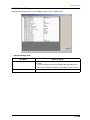
5.1 Outline of the Web Maintenance Tool ................................................................................................ 5-1
5.1.1
Web Maintenance Tool Functions...................................................................................... 5-1
5.2 Using the Web Maintenance Tool....................................................................................................... 5-3
5.2.1
Starting up the Web Maintenance Tool.............................................................................. 5-3
5.2.2
Shutting Down the Web Maintenance Tool ........................................................................ 5-4
5.2.3
Configuration of the Web Maintenance Tool ...................................................................... 5-5
5.2.4
Web Maintenance Tool Menu ............................................................................................ 5-6
5.3 Web Maintenance Tool Screens......................................................................................................... 5-8
5.3.1
FUNCTION Menu Screen ................................................................................................. 5-8
5.3.2
RESET Menu Screen ...................................................................................................... 5-16
5.3.3
SCP Menu Screen........................................................................................................... 5-20
5.3.4
SCU Menu Screen .......................................................................................................... 5-33
5.3.5
STATUS Screen............................................................................................................... 5-43
5.3.6
DIAG MEC Screen .......................................................................................................... 5-50
5.3.7
Handling UPGRADE Failure............................................................................................ 5-55
5.4 Setting and Adjustments Used in the Web Maintenance Tool.......................................................... 5-57
5.4.1
Laser Intensity Measurement .......................................................................................... 5-57
5.4.2
Checking Exposure Data Output ..................................................................................... 5-61
5.5 Log Analysis Tool ............................................................................................................................. 5-66
5.5.1
Outline of the Log Analysis Tool ...................................................................................... 5-66
5.5.2
Installing the Log Analysis Tool ....................................................................................... 5-67
5.5.3
Starting up and Quitting the Log Analysis Tool................................................................ 5-68
5.5.4
Using the Error Code Analysis Programme..................................................................... 5-69
5.5.5
Using the User Setting History Analysis Programme ...................................................... 5-71
5.5.6
Using the DICOM Log Analysis Programme ................................................................... 5-74
5.5.7
Log Analysis Tool Screens ............................................................................................. 5-77
v
Chapter 6 Maintenance
6.1 Items Requiring Regular Maintenance ............................................................................................... 6-1
6.1.1
Regular Maintenance Content and Cycle.......................................................................... 6-1
6.2 Heat Processing Unit Maintenance .................................................................................................... 6-3
6.2.1
Disassembling the Heat Processing Unit .......................................................................... 6-3
6.2.2
Cleaning the Opposing Rollers.......................................................................................... 6-5
6.2.3
Cleaning the Heat Processing Drum ................................................................................. 6-5
6.2.4
Replacing the Heat Processing Shaft Bearings ................................................................ 6-6
6.2.5
Replacing the Separator Unit ............................................................................................ 6-7
6.2.6
Replacing the Unwoven Cloth ........................................................................................... 6-8
6.2.7
Replacing the Antistatic Brush ........................................................................................ 6-10
6.3 Other Maintenance Items ................................................................................................................. 6-11
6.3.1
Cleaning the Adhesive Roller .......................................................................................... 6-11
Chap.7 Trouble Shooting
7.1 Troubleshooting .................................................................................................................................. 7-1
7.2 Trouble on the Printed Image. ............................................................................................................ 7-7
7.3 Error Message and Remedy............................................................................................................. 7-12
7.3.1
Error Code Structure ....................................................................................................... 7-12
7.4 Error Code and Remedy................................................................................................................... 7-13
7.5 Responding to the Film Jam ............................................................................................................. 7-99
Appendix
Time Zone Number Correspondence List...........................................................................................A-1
Film Management Information ............................................................................................................A-2
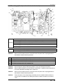
Board Diagram....................................................................................................................................A-3
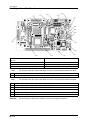
Mechanical Control Board ............................................................................................................ A-3
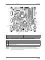
Main CPU Board (Main Board) ..................................................................................................... A-4
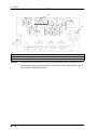
Print Engine Board (Print Board) .................................................................................................. A-5
Operation Control Board (OPE CTL) ............................................................................................ A-6
Operation Panel Board (OPE PNE) .............................................................................................. A-7
Heat Processing Drive Board ....................................................................................................... A-8
Heat Process Driver Board (anti-flicker) (HF-DRV) ...................................................................... A-9
Multi-Power Supply Board (contained in the electrical unit) ........................................................A-10
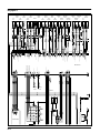
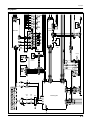
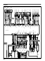
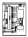
Overall Wiring Diagram.....................................................................................................................A-12
Wiring Diagram 1/4 ...........................................................................................................................A-13
Wiring Diagram 2/4 ...........................................................................................................................A-14
Wiring Diagram3/4 ............................................................................................................................A-15
Wiring Diagram4/4 ............................................................................................................................A-16
User Maintenance Menu...................................................................................................................A-17
Service Maintenance Menu ..............................................................................................................A-18
vi
Cautions Relating to Repairs and Installation
The following cautions must be observed when carrying out repair or installation work.
1.
To avoid accidents, only personnel properly trained and authorized by the manufacturer should remove
covers or touch internal parts.
2
The DRYPRO 771 incorporates a laser beam device (Class IIIb). Direct exposure of the skin or eyes to the
laser beam may cause serious damage. Always use protective goggles when carrying out repairs or
adjustments.
3.
Under no circumstances should any attempts be made to carry out operational procedures or adjustments
other than those described in this manual: exposure to harmful electromagnetic waves may result.
4.
To ensure safety while using or working on the DRYPRO 771, cautions shown on warning labels must be
observed at all times.
5.
The DRYPRO 771 contains internal parts that carry high voltage that may cause electrocution if touched.
Extreme caution must be exercised at all times.
6.
Be careful to avoid parts of the body or clothing becoming trapped or entangled in moving parts such as
fans.
7.
The DRYPRO 771 weighs approximately 150kg. Ensure that there is sufficient work space when carrying out
unpacking or installation work.
8.
Electrical circuitry in the DRYPRO 771 may be damaged by static electricity. Due care must be exercised
when handling the main body or any electrical parts removed during repair work.
9.
The DRYPRO 771 power supply must be switched off when removing circuit boards, disconnecting or
connecting connectors or cables. Under no circumstances should such procedures be carried out with the
power supply switched on: doing so may result in serious accidents.
10. A wrist band must always be worn when handling circuit boards.
11. The DRYPRO 771 incorporates a lithium battery. Improper replacement of the battery may cause damage:
only a qualified service engineer may carry out this procedure.
12. The DRYPRO 771 is a Class I laser device furnished with interlocks. The procedures described in this
manual must be followed when disengaging interlocks.
13. Do not move the device with the LAN cable connected as this may result in exposure of the cable to tension
resulting in damage to the LAN connector.
14. The specification of the RTC (real-time clock) used on the main board of the device is day differential ±1
second or less. The time and date should be checked every month.
DRYPRO MODEL 771 SERVICE MANUAL Ver.0.01 2003.10
1- i
Cautions Relating to Repairs and Installation
CAUTION
When disposing of the DRYPRO 771 main body, accessories, optional parts, consumables or
media. Strictly follow relevant local ordinances and regulations must be followed for disposal.
1- ii
DRYPRO MODEL 771 SERVICE MANUAL Ver.0.01 2003.10
Warning Label
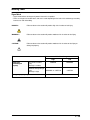
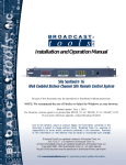
Signal Word
• Signal words indicate the degree of potential hazards in the product.
• There are 3 degrees of caution labels, and each is used depending on the level of risk and damage caused by
incorrect use and mishandling.
DANGER :
Failure to observe the caution will produce high risk of serious or fatal injury.
WARNING :
Failure to observe the caution will produce moderate risk of serious or fatal injury.
CAUTION :
Failure to observe the caution will produce moderate risk of serious or fatal injury or
damage to property.
Risk of the damage
Bodily injury
(and damage to
property)
Loss of life or serious
injury
(Damage is serious)
High
Low
DANGER
WARNING
Moderate damage or light
injury
WARNING or CAUTION
(Damage is light)
Damage to property only
CAUTION
CAUTION
DRYPRO MODEL 771 SERVICE MANUAL Ver.0.01 2003.10
1- iii
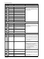
Warning Label List
:)
1.Caution label-1 warning of high-temperature (60:
:)
2.Caution label warning of high-temperature (100:
:)
3.Caution label-2 warning of high-temperature (60:
:)
4.Caution label-1 warning of high-temperature (130:
5.Caution: Laser-1
6.Class-1 Laser Product Label
7.Caution: Laser-2
1- iv
DRYPRO MODEL 771 SERVICE MANUAL Ver.0.01 2003.10
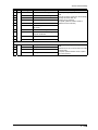
8.Caution: Laser-3
DRYPRO MODEL 771 SERVICE MANUAL Ver.0.01 2003.10
1- v
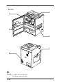
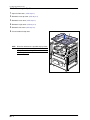
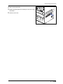
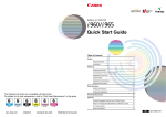
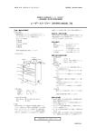
Locations of Warning Labels
•
Main Body
2
1
3
5
8
6
CAUTION
1- vi
To avoid the risk of electrocution or
burns, do not remove or soil labels.
DRYPRO MODEL 771 SERVICE MANUAL Ver.0.01 2003.10
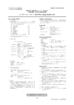
•
Heat Processing Unit
4
•
Main-scan Unit
7
CAUTION
Labels that have become illegible must
be replaced.
DRYPRO MODEL 771 SERVICE MANUAL Ver.0.01 2003.10
1- vii
Blank Page
Chapter 1 Product Outline
1.1 Specification
1.1
Specification
Product Name
: Laser Imager DRYPRO MODEL 771
CODE No.
: UL: 0582
CE: 0583
Model
: DRYPRO MODEL 771
Laser Source
: Semiconductor Laser
Film Type
: Medical Imaging Film SD-P, SD-PC, DR-P
Film Size
: 14 x 17 inch
14 x 14 inch
11 x 14 inch
Size to be determined when unit is installed.
Input Interface
: Ethernet 10 base-T / 100 base-TX
Protocol
: DICOM Print Management
Image Memory
: Hard Disk : 80GB Standard
: Print Memory : 128MB Standard
Processing Capacity
: Approx.110 sheets/hr. (Continuous printing of 14 X 17 inch size)
External Dimensions
: 630(W) x 600(D) x 1125(H)mm (with stand)
Weight
: 175kg (with stand)
External Dimensions
(Packed)
: 780(W) x 790(D) x 1410(H)mm (with stand)
Weight
(Packed)
: 205kg (with stand)
Power Source
: UL : Single Phase AC120V / 8.5A (60Hz)
CE : Single Phase AC220 ~ 240V / 4.5A (50 / 60 Hz)
Generated Heat
: Approx.950kJ (Approx. 226kcal / hr.)
Environmental Condi- :
tions
(when running)
15 ~ 30 ; / 30 ~ 70 %RH (No condensation)
Conditions for Transport and Storage
: - 20 ~ 60 ; / 20 ~ 90 %RH (No condensation)
Noise Level
: 55dB or less
Operation Panel
: LCD with membrance switch panel
Film Supply
: Tray
No. of Trays : 1(125 sheets / tray)
Image Data Input : 8 bits (256-step gradation) or 12bits (4096-step gradation)
(Depends on modality image signal.)
Output Gradation : 16384-step gradation (14 bits)
Image Mode : Pixel replication / Function interpolation process.
Pixel Size : 78.6µm fixed.
1- 1
DRYPRO MODEL 771 SERVICE MANUAL Ver.0.01 2003.10
1.1 Specification
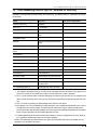
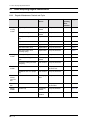
Image Matrix :
When Connected to REGIUS When Connected to Units Other than REGIUS
14X17 4,503 x 5,419 pixel
4,351 x 5,114 pixel
14X14 4,500 x 4,452 pixel
4,351 x 4,236 pixel
11x14 3,498 x 4,503 pixel
3,396 x 4,236 pixel
Number of Recorded : 1, 2, 4, 6, 8, 9, 12, 15, 16, 20, 24, 25, 30, 35, 36, 42, 48, 54, 56, 60, 63, 64
Frames
Positive / Nagative : Available.
Trim : Available.
Border : Black or Clear.
Stamp : Recorded on 1 line or 2 line of film (May be printed at top/bottom/left/right).
Deisity Correction : Furnished in main body.
Start Timer : Day / time settings possible.
Applicable Standards : IEC60601-1-2 : 2001, IEC60601-1, IEC60825
Remarks : DRYPRO 771 is manufactured in factories certified in compliance with ISO9001 : 2000,
EN ISO13485 : 2000, 93/42/EEC quality control standards as well as with medical
device directive FDA Pre market Notification 510(k) and GMP.
Accessories : Deodorant filter unit, Suction cups (spare), cutter, One-touch Spacers (2 pcs), Power
cable, Clamp (2 pcs), Exhaust duct, Warranty, Operation manual, Operation sheet,
Attached document for doctors, Inspection Sheet, Protective Parts (Red Parts), Recycle Bag, Accessory List
Consumable Parts : Deodorant filter
DRYPRO MODEL 771 SERVICE MANUAL Ver.0.01 2003.10
1- 2
1.2 Part Names
1.2
Part Names
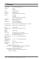
1.2.1 Front of DRYPRO Main Body
Operation Panel
Film Ejection Tray
Air Intake
Front Cover
Air Intake
Front Cover Lock
Disengagement Cover
Supply Tray
Power Breaker
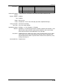
1.2.2 Rear of DRYPRO Main Body
Start Switch
Left Cover
Air Outlets
Power Supply
Connector
Serial Port
Power Cable
Ethernet Port
Supply Tray Open Button
1- 3
DRYPRO MODEL 771 SERVICE MANUAL Ver.0.01 2003.10
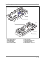
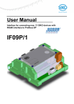
1.3 Functions of Each Part and Layout of Units
1.3
Functions of Each Part and Layout of Units
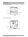
Operation Panel
Air Cooling Section (Deodorant filter)
Cooling/Ejection Section
(Primary/secondary cooling units)
(Ejection unit)
Heat Processing Section
Supply Section
Elevator Transport Section
(Elevator Transport Unit)
Pick-up Section
Tray Drive Unit
Tray Unit
Main Scanner Unit
Descent Transport Section
(Descent Transport Unit)
Electrical Unit
(Power Supply Unit)
Position Regulator/Sub-Scan Section
Electrical Unit
(Control box)
Optical Unit
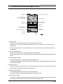
1.
Film flow
Supply Section
The supply unit is comprised of tray unit(1), pick-up(2) and tray drive unit(3).
The pick-up unit uses suction cups to pick up film one sheet at a time and convey the film to the descent
transport unit.
The tray drive unit operates the shutter (open/close), winds up the film package and locks/unlocks the tray
and front cover.
2.
Descent Transport Section
The descent transport section is comprised of descent transport unit(4).
The descent transport unit conveys film picked up from the supply tray to the position regulator and exposure
section.
3.
Position Regulator Section
The position regulator unit is comprised of position regulator unit(5).
The left/right positioning of the film fed by the descent transport unit is regulated by the position regulator and
sent to the sub-scan unit.
4.
Exposure Section
The exposure section is comprised of main-scan unit(6) and sub-scan unit(7). Laser scanning is carried out
along the film transportation to expose the image on the film.
5.
Elevator Transport Section
The elevator transport unit is comprised of elevator transport unit.
The elevator transport unit feeds exposed film to the heat processing unit.
6.
Heat Processing Section
This section is comprised of heat processing unit(9), heat processing drum drive and cleaning mechanisms
and develops the exposed film by exposure to heat, and to the cooling section.
DRYPRO MODEL 771 SERVICE MANUAL Ver.0.01 2003.10
1- 4
1.3 Functions of Each Part and Layout of Units
7.
Cooling Section
This unit is comprised of primary(10) and secondary cooling unit(11) as well as the cooling fan.
The cooling section cools the heat-developed film and feeds it to the ejection unit.
Each transport rollers in the cooling section are driven by the heat processing drum drive motor in the heat
processing section.
8.
Ejection section
This section is comprised of ejection unit(12) and densitometer unit(13).
The ejection unit ejects the cooled film to the ejection tray.
The densitometer unit measures the density of the developed film.
9.
Deodorant section
The deodorant section is comprised of deodorant fan mounted on the cooling fan unit and deodorant filter
unit(14).
Odors generated through heat processing will be removed by the deodorant filter.
10.Electrical Unit.
This unit is comprised of power supply unit(15) and the control box(16) as well as the mechanical control and
H-DRV boards located at the rear of the DRYPRO main body.
The power supply unit supplies power to the interior of the DRYPRO. The control box and mechanical control
board carry out overall control of the DRYPRO, communication with diagnostic devices and image data processing/control.
11.Operation Panel
The operation panel is comprised of operation panel unit(17), and used to control the DRYPRO and to make
settings.
The operation switch used to start up the DRYPRO is located on this unit.
1- 5
DRYPRO MODEL 771 SERVICE MANUAL Ver.0.01 2003.10
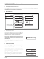
1.4 Block Diagram
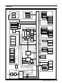
1.4
Block Diagram
Operation Panel Unit
Supply Feed Motor
Filter Detection Sensor
Display Module
Start
Switch
Pick-up Unit
Cooling Unit
Operation
Control
Board
Operation Panel
Board
Suction Cup Link Motor
Deodorant Fan
Film Suction Pump
Secondary Cooling Fan
Supply Ejection Sensor
Suction Release Valve
Suction Cup Home Sensor
Cooling/Ejection Unit
Empty Sensor
Primary Cooling Temp. Sensor
Supply Temp. Sensor
Secondary Cooling Temp. Sensor
Densitometer Entrance Sensor
Tray Drive Unit
Exposure Unit
Sub-scan Unit
Main-scan Unit
Ejection Motor
LD HFM Board
Densitometer
Unit
Shutter Open/Close Motor
V-sync senor
Polygon Motor
Sub-scan
In-port Sensor
Polygon
Drive
Board
Barrier Bag Collection Motor
Shutter Open Sensor
Tray Lock Solenoid
Shutter Close Sensor
Front Cover Disengaging Solenoid
Sub-scan Motor
Interlock Switch
Heat Processing Unit
Heat Processing
Drum Monitor
LD Drive Board
Nip Solenoid
LD Temp.
Control Board
Nip Drive
Board
Cleaning Position
Detection Sensor
Front Cover Close Sensor
Mechanical
Control
Board
Descent Transport
Descent Transport
Nip Close Sensor
Descent Transport Nip Motor
Heat Processing
Drive Motor
Jam Release Cover
Close Sensor
Cleanig Retraction Motor
Heat Processor
Elevator Transport Unit
Elevator Transport Motor
Heat Processing
Temp. Sensor-F
Control Box
Heat Processing
Temp. Sensor-C
Elevator Transport
Nip Close Motor
Elevator Transport Nip Motor
Heat Processing Unit
Entrance Sensor
Print Control Board
Heat Processing
Temp. Sensor-R
Tray Lock Sensor
Main Heater-1
Rear Cover Close Sensor
Serial Connector
Main Heater-2
Heat Processing
Drive Board
Front Heater
Monitor Connector
Main CPU Board
Position Regulation Unit
Keyboard Connnector
Rear Heater
LAN Connector
Hard Disk
Position Regulation
Nip Motor
CF
Position Regulation Feed Motor
Circuit
Breaker
Justification Motor
AC100V
Position Regulation Nip Motor
Power Supply Unit
Justification
Home Sensor
Justification
Position Sensor
DC+12V, DC5V
DC24V,DC-12V
AC IN
(AC100V)
Circuit
Breaker
Noise
Filter
AC100V
Multi-Power
Supply Board
SUP1
DC+12V
Interlock X1
DC24V
DC5V,DC12V
DRYPRO MODEL 771 SERVICE MANUAL Ver.0.01 2003.10
1- 6
Blank Page
1.5 Tools, Measuring Devices, Jigs, etc., Required for Servicing
1.5
Tools, Measuring Devices, Jigs, etc., Required for Servicing
In addition to standard tools recommended by the manufacturer, the following tools are required for servicing of
the DRYPRO.
Name
Remarks
Interlock release key
Supplied
Allen keys
L shape type
Main Service Applications
Tape (gum tape, etc.)
Laser-protective goggles
LS-5-LD2 manufactured by Sigma
Koki
Light power meter
IR card
06DLA01 manufactured by Melles
Griot
Exposure data output check jig*1
Supplied
Extension cables for exposure
unit*2
Supplied
Densitometer
Isopropyl Alcohol
Triflow (Lubricant)
Lens cleaner
Vacuum cleaner
Work gloves
Clock drivers*3
Flat Head Driver
Precision scraper
Automatic pen may also be used.
Push/pull gauge
Standard value: 50gf - 1kgf
Display Monitor*4
Monitor capable of display of 1024
X 768 or more.
101 keyboard (English)*5
Compatible with PS/2 connector
*1 The exposure data output check jig is used to check data output from the control box to the exposure unit.
Since this is inserted in the middle of the cable, one more exposure I/F cable is provided.
*2 This is a set of extension cables used when pulling out the exposure unit for testing. The set comprises four
cables, two for connection to the main-scan unit and two for connection to the position regulator/sub-scan
unit.
*3 This is useful when removing the lithium button battery from the main board.
*4 This monitor is for a PC with DSUB15 pin video connector, and is capable to monitor XGA (1024 x 768: HFreq 48.4kHz, V-Freq 60Hz) images. A monitor normally used for PC may be sufficient, but one that is
exclusively for VGA may not display properly. Characters may be mis-positioned depending on the monitor,
but this may be corrected using the monitor adjustment function.
*5 A USB keyboard cannot be connected. Note that although a Japanese keyboard can be used, certain of
the key positions will differ from those on an English keyboard.
• Remove the control box cover located on the rear panel of the DRYPRO and connect the monitor and 101
keyboard to the control box connectors.
DRYPRO MODEL 771 SERVICE MANUAL Ver.0.01 2003.10
1- 8
Blank Page
Chapter 2 Disassembly and Assembly
2.1 Before Disassembling
2.1
2.1.1
Before Disassembling
Cautions Regarding Disassembly/Assembly
• To avoid the risk of electrocution, switch off the main body
or facility breaker after ensuring that the main body power
supply is switched off before proceeding with work.
• The heat processing unit and its periphery will retain high
temperature for a time after the main body power supply
has been switched off. To avoid the risk of burns, be sure
to allow a sufficient cooling-off period before commencing
work.
• To avoid the risk of electrocution when handling circuit
boards, always wear an earth strap on the wrist and
ensure that the clip at the end of the strap cord is attached
to a metallic part of the main body suitable for earth connection.
• To protect circuitry, always wear an earth strap.
• When carrying out assembly work, re-attach cable bundle
fasteners and ensure that cables are not entangled in or
pulled taught by components.
Earth strap
2- 1
DRYPRO MODEL 771 SERVICE MANUAL Ver.0.01 2003.10
2.1 Before Disassembling
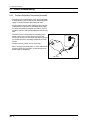
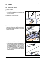
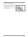
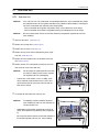
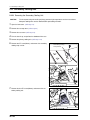
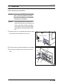
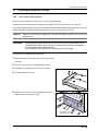
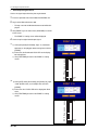
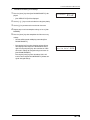
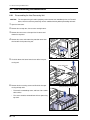
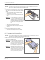
2.1.2
Opening the Front Cover
The following procedure should be followed to open the front cover
when the DRYPRO 771 power supply is switched off.
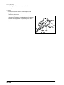
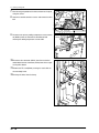
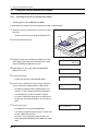
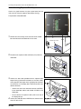
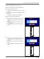
1.
Using a flat head screwdriver with a narrow tip, remove the
plastic cover at the front of the right cover.
CAUTION
Make sure that the plastic cover is replaced to
protect the film from light after the work, otherwise the film may be get fogged.
Front cover
Cover
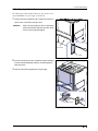
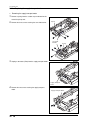
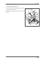
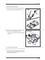
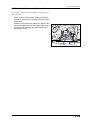
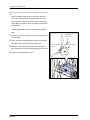
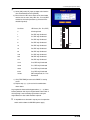
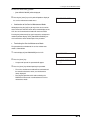
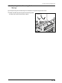
2.
Insert the narrow shaft of the screwdriver(120mm or longer)
into the uncovered opening and press and disengage the
front cover latch.
3.
Open the front cover by pulling on the right edge.
Front cover latch
DRYPRO MODEL 771 SERVICE MANUAL Ver.0.01 2003.10
2- 2
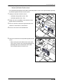
2.2 Removing External Covers
2.2
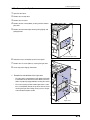
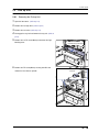
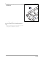
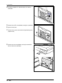
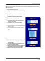
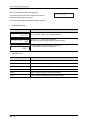
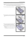
2.2.1
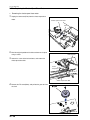
1.
Removing External Covers
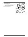
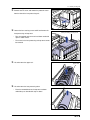
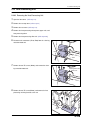
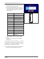
Removing the Rear Top Cover
Remove the three screws(M4x12) securing the rear top
cover.
2.
Loosen the right and left screws “a” at the top of the rear
cover.
3.
Remove the rear top cover while slightly pulling the top of
right and left covers outward.
Rear Top Cover
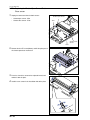
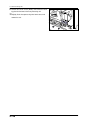
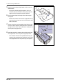
2.2.2
Removing the Rear Cover
1.
Remove the Rear Top Cover.
2.
Remove the eight screws (M4x12) securing the rear cover.
3.
Lift the rear cover slightly and remove.
Rear Cover
2- 3
DRYPRO MODEL 771 SERVICE MANUAL Ver.0.01 2003.10
2.2 Removing External Covers
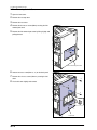
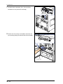
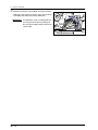
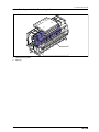
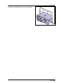
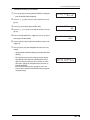
2.2.3
Removing the Right Cover
1.
Open the front cover.
2.
Remove the rear top cover.
3.
4.
Remove the rear cover.
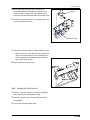
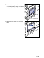
Remove the four screws(M4x6) securing the film-removal
port cover.
5.
Remove the film-removal port cover by lifting slightly and
pulling forward.
Film-removal port cover
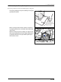
6.
Loosen one truss screw(M4x12) on the back panel.
7.
Remove the six screws (M4x12) securing the right cover.
8.
Lift the right cover slightly and remove.
a
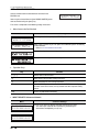
•
a
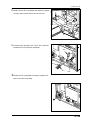
Remarks for reinstallation of the right cover
•
•
b
The right cover is attached to the main body’s frame with
its two hooks on the back of the cover. Make sure these
hooks are properly engaged before securing the screws.
a
The screw securing the film-removal port cover is short
truss screws(M4x6). Do not mix up these with the screw
securing the right cover. Doing so may cause a film jam
at the elevator transport section.
Hook
c
c
Right cover
DRYPRO MODEL 771 SERVICE MANUAL Ver.0.01 2003.10
2- 4
2.2 Removing External Covers
2.2.4
Removing the Left Cover
1.
Open the front cover.
2.
Remove the rear top cover.
3.
4.
Remove the rear cover.
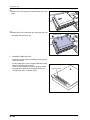
Remove the four truss screws(M4x6) securing the filmremoval port cover.
5.
Remove the film-removal port cover by lifting slightly and
pulling forward.
Film-removal port cover
6.
Loosen one truss screw(M4x12, “a”) on the back panel.
7.
Remove the six truss screws (M4x12) securing the left
cover.
8.
a
Lift the left cover slightly and remove.
a
a
b
b
Hook
a
c
Left cover
c
2- 5
DRYPRO MODEL 771 SERVICE MANUAL Ver.0.01 2003.10
2.2 Removing External Covers
•
Remarks for reinstallation of the right cover
•
The right cover is attached to the main body’s frame with
its two hooks on the back of the cover. Make sure these
hooks are properly engaged before securing the screws.
•
The screw securing the film-removal port cover is short
truss screws(M4x6). Do not mix up these with the screw
securing the right cover. Doing so may cause a film jam
at the elevator transport section.
•
When replacing the film -removal port cover, pull out the
stopper from the descent transport unit, and insert the
plastic part of the stopper in the position shown in the
right figure. If the stopper is hanging inside the descent
transport unit, it may cause film jam in the descent transport section.
DRYPRO MODEL 771 SERVICE MANUAL Ver.0.01 2003.10
2- 6
2.2 Removing External Covers
2.2.5
Removing the Top Cover
1.
Open the front cover. (reffer to p.2-2)
2.
Remove the rear top cover. (reffer to p.2-3)
3.
Remove the rear cover. (reffer to p.2-3)
4.
Remove the right cover. (reffer to p.2-4)
5.
6.
Remove the left cover. (reffer to p.2-5)
Lift and remove the top cover.
Top Cover
HINT : When the maintenance is possible only by removing the top cover, remove only two screws each on
the top of rear, left and right covers after removing
the rear top cover.
2- 7
DRYPRO MODEL 771 SERVICE MANUAL Ver.0.01 2003.10
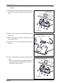
2.3 Tray Unit
Tray Unit
2.3
2.3.1
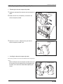
1.
2.
Open the front cover.
Press the tray release button on the rear panel.
•
3.
Removing the Tray Unit
The tray unit lock will disengage and the tray will slide
out a few centimeters.
Pull out the tray unit to its fullest extent.
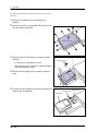
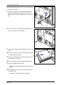
Tray release button
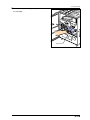
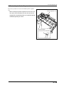
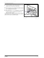
4.
Remove the tray unit from the rails by pulling forward at the
same time as pressing in the stoppers (metal part that can
be located under the black plastic cover at the rail end) on
each side of the tray unit.
•
Cautions for removal of the tray unit.
•
Stopper
Left Rail
Continuing the work with the slide rail pulled out after the
tray unit is removed may result in damage of the rail or
injury by being caught on the rail, Push the rail back in
the main body before starting the work. Pressing in the
lock metal at the rear end of the rail (push down at the
left, push up at the right) releases the lock and enables
to push the rail back.
Lock
Lock
Right Rail
DRYPRO MODEL 771 SERVICE MANUAL Ver.0.01 2003.10
2- 8
2.3 Tray Unit
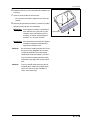
•
Installing the tray unit
Reverse the procedure for removal to install the tray unit.
•
Installation of the tray unit shall be carried out with the
slide rail pushed into the main body.
•
Placing the rear slide part at the rear end of the tray on
the slide rail, and pushing in the tray horizontally makes
the installation of the tray on the rail easier.
2- 9
DRYPRO MODEL 771 SERVICE MANUAL Ver.0.01 2003.10
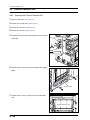
2.4 Pick Up Unit
2.4
2.4.1
Pick Up Unit
Removing the Pick-up Unit
1.
Open the front cover. (reffer to p.2-2)
2.
Remove the rear top cover. (reffer to p.2-3)
3.
Remove the rear cover. (reffer to p.2-3)
4.
Disengage the tray lock and remove the tray unit. (reffer to
p.2-8)
5.
Remove the six TP screws(M3x6) and remove the light
blocking cover.
6.
Light-Blocking Plate (tray)
Remove the TP screws(M3x6) securing lever-BC and
remove the lever from its spindle.
Lever-BC
DRYPRO MODEL 771 SERVICE MANUAL Ver.0.01 2003.10
2- 10
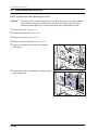
2.4 Pick Up Unit
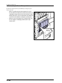
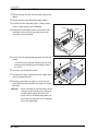
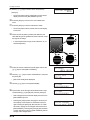
7.
Disconnect three connectors (JP12, JP13 and JP99)
located on the rear panel of the main body.
JP13
8.
JP99
JP12
Remove the two securing screws(M4x8) and remove the
pick-up unit by pulling it out from the front of the main body.
Pick-up unit
2- 11
DRYPRO MODEL 771 SERVICE MANUAL Ver.0.01 2003.10
2.4 Pick Up Unit
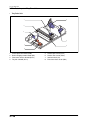
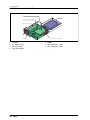
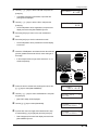
2.4.2
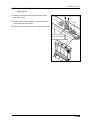
Parts Layout of Pick Up Unit
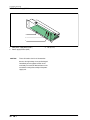
5
1
3
4
2
6
7
8
1.
2.
3.
4.
Suction cup arm motor (M2)
Supply feed motor (PM1)
Film suction pump (P1)
Suction release valve (MV1)
5.
6.
7.
8.
Empty sensor (SE4)
Suction cup home sensor (PS10)
Supply Exit sensor (PS17)
Supply temperature sensor (TH6)
DRYPRO MODEL 771 SERVICE MANUAL Ver.0.01 2003.10
2- 12
2.4 Pick Up Unit
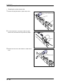
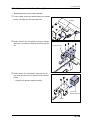
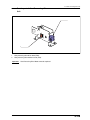
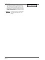
2.4.3
•
1.
Replacing the Suction Cup Arm Motor
Removing the suction cup arm motor.
Cut the tie band that secures the cable for the suction cup
Suction Cup Arm Motor
arm motor, and unplug the relay connector (JP50).
JP50
Tie band
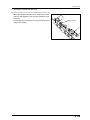
2.
Remove the two screws, and remove the suction cup arm
Suction Cup Arm Motor
motor together with entire motor bracket.
Motor Bracket
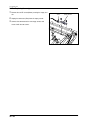
3.
Remove the four screws, and remove the suction cup arm
Suction Cup Arm Motor
motor from the motor bracket.
Motor Bracker
2- 13
DRYPRO MODEL 771 SERVICE MANUAL Ver.0.01 2003.10
2.4 Pick Up Unit
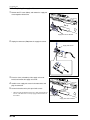
•
Installing the suction cup arm motor.
Reverse the procedure for removal to install the suction cup arm
motor.
• When securing the screws to attach the motor bracket to the
pick up unit, press the motor bracket against the pick up unit
Press against the gear til it contacts
so that the motor shaft gear contacts with the cam gear
before securing the screws.
• Fix the cable for the suction cup arm motor on the pick up
unit using a new tie band.
DRYPRO MODEL 771 SERVICE MANUAL Ver.0.01 2003.10
2- 14
2.4 Pick Up Unit
2.4.4
•
1.
Replacing the supply transport motor
Removing the supply transport motor
Remove a spring from the suction cup arm located on the
rear of the pick up unit.
2.
Remove the three screws securing the arm shaft bracket.
Spring
Arm Shaft
Bracket
3.
Spring
Unplug a connector (JP63) from the supply transport motor.
JP63
Supply Transport
Motor
4.
Remove the two screws securing the supply transport
motor.
2- 15
Supply Transport Motor
DRYPRO MODEL 771 SERVICE MANUAL Ver.0.01 2003.10
2.4 Pick Up Unit
5.
Slightly lift the suction cup arm, and remove the supply
Supply Transport Motor
transport motor.
Suction
Cup Arm
•
Installing the supply transport motor
Reverse the procedure for removal to install the supply transport
motor.
• Make sure to hook the sprint on the suction cup arm after
securing the arm shaft bracket with screws.
DRYPRO MODEL 771 SERVICE MANUAL Ver.0.01 2003.10
2- 16
2.4 Pick Up Unit
2.4.5
•
1.
Replacing the film suction pump
Removing the film suction pump
Cut the tie band, and pull out the silicon tube from the film
suction pump.
Silicon Tube
Tie Band
Film Suction Pump
2.
Cut the tie band that is fixing the cable for film suction pump,
JP70
and unplug the relay connector(JP70).
Tie Band
3.
Remove the two screws, and remove the film suction pump.
2- 17
Film Suction Pump
DRYPRO MODEL 771 SERVICE MANUAL Ver.0.01 2003.10
2.4 Pick Up Unit
•
Installing the film suction pump
Reverse the procedure for removal to install the Þlm suction pump
• Attach the silicon tube at the intake port side of the pump,
and secure it using a tie band.
• Fix the cable for the film suction pump on the pick up unit
using a new tie band.
Air Intake
DRYPRO MODEL 771 SERVICE MANUAL Ver.0.01 2003.10
2- 18
2.4 Pick Up Unit
2.4.6
•
1.
Replacing the suction release valve
Removing the suction release valve
Remove the tube joint from the suction release valve.
Suction Release Valve
Joint
2.
Cut the tie band that is securing the cable for suction
JP69
release valve, and remove the relay connector (JP69).
Tie Band
3.
Remove the two screws, and remove the suction release
valve.
Suction Release Valve
2- 19
DRYPRO MODEL 771 SERVICE MANUAL Ver.0.01 2003.10
2.4 Pick Up Unit
•
Installing the suction release valve
Reverse the procedure for removal to install the suction release valve.
• When connecting the tube joint to the suction release valve,
connect it after applying a new seal tape around the screw
of the joint.
• Fix the cable for the suction release valve on the pick up unit
Apply seal tape
using a new tie band.
DRYPRO MODEL 771 SERVICE MANUAL Ver.0.01 2003.10
2- 20
2.4 Pick Up Unit
2.4.7
1.
Replacing the empty sensor
Remove the two TP screws(M3x6) securing the empty sensor.
2.
Unplug the connector (JP33) from the empty sensor.
3.
Connect the connector to the new empty sensor, and
JP33
Empty Sensor
secure it with the two screws.
2- 21
DRYPRO MODEL 771 SERVICE MANUAL Ver.0.01 2003.10
2.4 Pick Up Unit
2.4.8
1.
Replacing the suction cup home sensor
Remove the connector (JP34) from the suction cup home
sensor.
Suction Cup HP Sensor
JP34
2.
Press the claw of the suction cup home inward, and remove
Suction Cup HP Sensor
the suction cup home sensor.
3.
Install the new suction cup home sensor in the mount hole,
and plug the connector.
DRYPRO MODEL 771 SERVICE MANUAL Ver.0.01 2003.10
2- 22
2.4 Pick Up Unit
2.4.9
1.
Replacing the supply exit sensor
Remove one TP screw (M3x6), and remove the supply exit
sensor together with bracket.
Supply Exit Sensor Bracket
2.
Unplug the connector (JP88) from the supply exit sensor.
Supply Exit Sensor
JP88
3.
Press the claws (4 locations) of the supply exit sensor
inward, and remove the supply exit sensor.
4.
Install the new supply exit sensor in the mount hole, and
Bosses
plug the connector.
5.
Secure the bracket on the pick up unit with screws.
•
When securing the bracket with screws, make sure that the two
bosses of the chassis are correctly engaged with the holes on
the bracket.
Positioning Holes
Supply Exit Sensor Bracker
2- 23
DRYPRO MODEL 771 SERVICE MANUAL Ver.0.01 2003.10
2.4 Pick Up Unit
2.4.10 Replacing the supply temp. sensor
•
1.
Removing the supply temp. sensor
Cut the tie band securing the cable for supply temp. sensor,
and unplug the relay connector.
2.
Supply Temp. Sensor
Tie Band
Connect the new supply temp. sensor, and secure it with the
tie band.
Tie Band
JP98
Tie Band
DRYPRO MODEL 771 SERVICE MANUAL Ver.0.01 2003.10
2- 24
2.4 Pick Up Unit
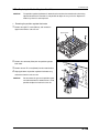
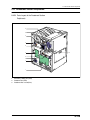
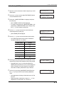
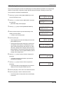
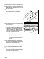
2.4.11 Installing the pick up unit
1.
Engage the pick up unit with the rail of the main body’s
frame, and push it back horizontally till it stops.
2.
Secure the pick up unit on the main body with two TP
screws(M4x12).
3.
Loosen the three screws securing the plate for the relay
gear in the rear of the main body.
4.
Loosen three screws
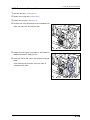
Insert a parallel pin (4φ) into the center hole of the gear
plate.
•
Insert the parallel pin 45 to 50mm in depth so that the tip
of the pin reaches through the hole on the gear shaft of
the pick up unit.
2- 25
DRYPRO MODEL 771 SERVICE MANUAL Ver.0.01 2003.10
2.4 Pick Up Unit
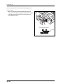
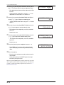
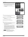
5.
With the tip of parallel pin being inserted into the hole on the
gear shaft of the pick up unit, secure the three screws on
the gear plate.
6.
Gear Plate
Unplug the parallel pin, and connect the three connectors
(JP12, JP13, JP99).
Parallel Ping
Relay Gear
Drive Gear
at Supply Side
DRYPRO MODEL 771 SERVICE MANUAL Ver.0.01 2003.10
2- 26
2.5 Tray Drive Unit
2.5
2.5.1
Tray Drive Unit
Tray Drive Unit
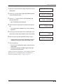
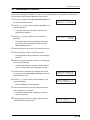
1.
Open the front cover. (reffer to p.2-2)
2.
Remove the rear top cover. (reffer to p.2-3)
3.
Remove the rear cover. (reffer to p.2-3)
4.
Disengage the tray lock, and remove the tray unit.
5.
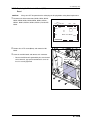
Remove the light-blocking plate (tray).
6.
Disconnect two connectors (JP86 and JP87) located on the
rear panel of the main body.
JP87
JP86
7.
Remove the two TP screws(M4x8) securing the tray drive
unit from the rear panel of the main body.
2- 27
DRYPRO MODEL 771 SERVICE MANUAL Ver.0.01 2003.10
2.5 Tray Drive Unit
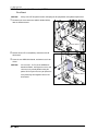
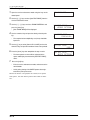
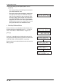
8.
Remove the tray drive unit by pulling it out from the front of
the main body.
Tray drive unit
DRYPRO MODEL 771 SERVICE MANUAL Ver.0.01 2003.10
2- 28
2.5 Tray Drive Unit
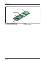
2.5.2
•
Parts Layout of Tray Drive Unit
Tray Drive Unit
1
2
5
3
4
7
6
8
1.
2.
3.
4.
Shutter open/close motor (PM8)
Barrier wrapping removal motor (M3)
Front cover release solenoid (SOL2)
Tray lock solenoid (SOL1)
2- 29
5.
6.
7.
8.
Shutter open sensor (PS11)
Shutter close sensor (PS12)
Interlock switch (S3)
Front cover close sensor (MS1)
DRYPRO MODEL 771 SERVICE MANUAL Ver.0.01 2003.10
2.5 Tray Drive Unit
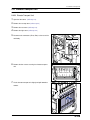
2.5.3
•
1.
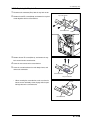
Replacing the Film Package Rewind Motor
Removing the film package rewind motor
Remove the E-ring from the gear shaft of the film package
rewind motor and the torque limiter gear.
E-Ring
Torque Limitter Gear
2.
Remove the three TP screws(M4x8), and remove the film
package rewind motor from the motor bracket.
3.
Unplug the relay connector(JP51) for the motor cable.
Film Package
Rewind Motor
JP51
4.
Loosen the set screw and pull out the gear shaft from the
motor shaft.
Set Screw
Gear Shaft
DRYPRO MODEL 771 SERVICE MANUAL Ver.0.01 2003.10
2- 30
2.5 Tray Drive Unit
•
Installing the film package rewind motor
Reverse the procedure for removal of the Þlm package rewind motor
to install the motor.
• When installing the gear shaft on the motor shaft, insert the
gear shaft into the motor shaft to its full end, then secure it
with set screw. At this point, make sure that the set screw is
Set Screw
pressed against the flat edge of D-cut motor shaft.
• Since the torque limiter has a one-way clutch structure, failure to install it in correct orientation will result in failure to
rewind the film package due to the slippage of the shaft.
Make sure the orientation is correct as shown in the figure in
the right.
2- 31
DRYPRO MODEL 771 SERVICE MANUAL Ver.0.01 2003.10
2.5 Tray Drive Unit
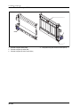
2.5.4
•
1.
Replacing the Front Cover Release Solenoid
Removing the front cover release solenoid
Cut the tie band securing the solenoid cable on the solenoid
bracket, and unplug the relay connector(JP58).
2.
Remove the three TP screws(M4x8) securing the solenoid
mount plate, and remove the mount plate from the tray drive
unit .
3.
Tie Band
Solenoid Bracker
Remove the four TP screws(M4x8), and remove the coil
assy of the front cover release solenoid from the solenoid
bracket.
•
Plunger of the solenoid cannot be removed.
Front Cover
Release Solenoid
Plunger
DRYPRO MODEL 771 SERVICE MANUAL Ver.0.01 2003.10
2- 32
2.5 Tray Drive Unit
•
Installing the front cover release solenoid
Reverse the procedure for removal of the front cover release solenoid
to install it.
• Because the plunger cannot be replaced, pull out the
plunger from the new solenoid, and use the coil assy to
replace the defective one.
• When installing the solenoid bracket on the tray drive unit,
make sure that the bosses (two locations) on the top panel
of the unit are engaged with the positioning holes of the
Positioning
Hole
bracket.
Bosses
2- 33
DRYPRO MODEL 771 SERVICE MANUAL Ver.0.01 2003.10
2.5 Tray Drive Unit
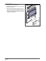
2.5.5
Replacing the Tray Lock Solenoid
•
Removing the tray lock solenoid
1.
Cut the tie band securing the solenoid cable on the solenoid bracket, and unplug the relay connector(JP51).
Tie Band
JP51
2.
Remove the three TP screws(M4x8), and remove the coil
assy of the tray lock solenoid from the bracket.
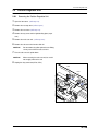
•
The plunger of the solenoid cannot be removed from the
link plate.
•
Installing the tray lock solenoid
Reverse the procedure for removal of the tray lock solenoid to install
it.
• Because the plunger of the solenoid cannot be replaced,
pull out the plunger from the new solenoid, and use the coil
assy to replace the defective one.
DRYPRO MODEL 771 SERVICE MANUAL Ver.0.01 2003.10
2- 34
2.5 Tray Drive Unit
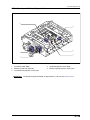
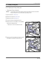
2.5.6
•
1.
Replacing the Shutter Open/Close Motor
Removing the shutter open/close motor
Unplug the connector(JP49) from the shutter open/close
motor.
Shutter Open/Close Motor
JP49
2.
Mark the original position of the belt tensioner on the plate
Belt Tensioner
using a scriber.
3.
Loosen the screw of the belt tensioner, and remove the
shutter open/close belt.
Scribe
the position
Shutter Open/Close Belt
4.
Remove the TP screw(M3x6), and pull out the gear-56 from
the shaft.
2- 35
Gear-56
DRYPRO MODEL 771 SERVICE MANUAL Ver.0.01 2003.10
2.5 Tray Drive Unit
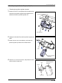
5.
Remove the two TP screws(M3x6), and remove the shutter
open/close motor.
•
•
Shutter Open/Close Motor
The shutter open/close motor can be pulled out through
the rectangular hole on the tray drive unit.
Installing the shutter open/close motor
Reverse the procedure for removal of the shutter open/close motor to
install it.
• When securing the belt tensioner, align the belt tensioner to
the position marked with a scriber before removal.
• Whenever the shutter open/close belt is replaced, measure
the belt tension using a push pull gauge. Press the belt of
the belt tensioner with the push pull gauge, and secure the
screw when it measures 600gf.
Belt Tensioner
Push Pull Gauge
DRYPRO MODEL 771 SERVICE MANUAL Ver.0.01 2003.10
2- 36
2.5 Tray Drive Unit
2.5.7
1.
Replacing the Shutter Open Sensor/Shutter
Close sensor
Unplug the connectors from the both sensors.
Shutter Open Sensor
•
Shutter open sensor : JP35
•
Shutter close sensor : JP36
JP35
Shutter Colse
Sensor
JP36
2.
Remove the four TP screws(M4x8), and lift the plate part of
the shutter open/close mechanism.
3.
Press the claw of the sensor to be replaced inward, and
remove it from the plate.
4.
Install the new sensor in the installation hole of the plate.
2- 37
DRYPRO MODEL 771 SERVICE MANUAL Ver.0.01 2003.10
2.5 Tray Drive Unit
5.
Secure the plate of the shutter open/close mechanism on
the tray drive unit with screws.
•
6.
When securing the plate on the tray drive unit, make
sure that the four bosses on the top panel of the unit
engage with the positioning holes of the plate.
Plug the connector to the sensor.
Positioning
Holes
Bosses
DRYPRO MODEL 771 SERVICE MANUAL Ver.0.01 2003.10
2- 38
2.5 Tray Drive Unit
2.5.8
1.
Replacing the Interlock Switch/Front cover
Close Sensor
Unplug the connector from the sensor/switch to be
replaced.
•
Interlock Switch : JP42
•
Front cover close sensor : JP44
JP42
Front Cover Close Senser
Interlock Switch
JP44
2.
Remove the three TP screws(M4x8), and lift the sensor
bracket.
3.
Sensor Bracket
When replacing the front cover close sensor, remove the
two TP screws(M3x15) from the sensor (micro-switch), and
remove the sensor.
Front Cover Close Senser
4.
Secure the new sensor with screws.
2- 39
DRYPRO MODEL 771 SERVICE MANUAL Ver.0.01 2003.10
2.5 Tray Drive Unit
5.
When replacing the interlock switch, remove the TP
screw(M3x6) to detach the damper, then pull out in the
direction shown in the figure in the right while pressing
inward the claws located at both side of the interlock switch.
6.
Damper
Install the new interlock switch in the installation hole, and
secure the damper with screws.
Interlock Switch
7.
Secure the sensor bracket on the tray drive unit with screws.
•
8.
When installing the sensor bracket on the tray drive unit,
make sure that the two bosses on the top panel of the
unit are engaged with the positioning holes (two locations) on the sensor bracket.
Positioning
Hole
Plug the connector to each sensor.
Positioning
Hole
Bosses
2.5.9
1.
Installing the Tray Drive Unit
Engage the tray drive unit with the rail of the main body’s
frame, and push back horizontally till it stops.
2.
Secure the tray drive unit on the main body with two TP
screws(M4x8).
3.
Plug the two connectors(JP86, JP87).
DRYPRO MODEL 771 SERVICE MANUAL Ver.0.01 2003.10
2- 40
2.6 Main-scan Unit
Main-scan Unit
2.6
2.6.1
Removing the Main-scan Unit
CAUTION
Do not attempt to disassemble nor adjust the main-scan unit. Should any failure happen on the
main-scan unit, replace the entire unit.
CAUTION
Be careful not to apply any shock to the unit when removing or transporting the main-scan unit.
Failure to protect teh unit from shock may adversary affect the image quality.
IMPORTANT
•
Always measure and check the beam power whenever the main-scan unit is replaced.
Removing the main-scan unit
1.
Open the front cover. (reffer to p.2-2)
2.
Remove the rear top cover. (reffer to p.2-3)
3.
Remove the rear cover. (reffer to p.2-3)
4.
5.
Press the tray release button and disengage the tray lock.
Pull out the tray and loosen the two TP screws(M4x8) on the
Tray cover
tray cover.
6.
Lift and remove the tray cover.
7.
Remove the six TP screws(M3x6) and remove the light
blocking cover (exposure unit).
Light blocking cover
(Exposure unit)
2- 41
DRYPRO MODEL 771 SERVICE MANUAL Ver.0.01 2003.10
2.6 Main-scan Unit
8.
Remove the two TP screws(M4x8) and remove the ground
GND Wire
wire(2pcs) from teh both sides of the sub-scan unit.
GND Wire
9.
Disconnect four connectors (JP14, JP15, JP21 and JP22)
located on the rear panel of the main body.
JP21
JP14
JP15
JP22
10.Remove the TP screw(M4x8) securing the exposure unit
from the rear of the main body.
DRYPRO MODEL 771 SERVICE MANUAL Ver.0.01 2003.10
2- 42
2.6 Main-scan Unit
11.Remove the entire exposure unit from the front of the main
body.
12.Remove the five TP screws(M4x18) securing the main-scan
unit and lift and remove the unit.
•
Main-scan unit
Installing the Main-scan Unit
• The main-scan unit may be installed by reversing the procedure for removal.
• The dust-proof glass at laser exit port should be cleaned
before installing the main-scan unit.
A lens cleaner should be used for this purpose and the
dust-proof glass wiped always moving the cloth in the
same direction and at a constant speed.
2- 43
Dust-Proof Glass
DRYPRO MODEL 771 SERVICE MANUAL Ver.0.01 2003.10
2.7 Sub-Scan Unit
2.7
2.7.1
Sub-Scan Unit
Sub-scan Unit
CAUTION
If the sub-scan unit is left removed for an extended period of time, any accumulated dust should
be removed from the sub-scan guides and rollers using a blower or duster before re-installing the
unit. Dust accumulation may adversely affect image quality.
- Dust accumulation on the guides may produce sharp, vertical black lines on the image.
- Dust accumulation on the rollers may produce 63mm pitch horizontal lines on the image.
CAUTION
Be careful not to touch the belts on the front and back of the position regulator/sub-scan unit
when handling.
1.
Open the front cover. (reffer to p.2-2)
2.
Remove the rear top cover. (reffer to p.2-3)
3.
Remove the rear cover. (reffer to p.2-3)
4.
Remove the tray cover and the light blocking cover (exposure unit). (reffer to p.2-41)
5.
Remove the entire exposure unit, and remove main-scan
unit. (reffer to p.2-41)
6.
Remove the four TP screws(M4x8) securing the scan unit
regulator/sub-scanning unit
(two screws on each of the slide rails).
CAUTION
•
7.
Do not remove the yellow painted screws from
the slide rails. Doing so may result in the position regulator/sub-scan unit dropping.
A driver with a short handle, such as a stubby screwdriver, should be used to remove these screws since
space between the left side of the of the unit and the
front cover is limited.
Lift straight up and remove the sub-scan unit.
CAUTION
The following cautions should be observed
when handling the sub-scan unit and work carried out with due care.
•
Avoid exposing the position regulator/sub-scan unit to
shock. Such exposure may adversely affect image quality.
•
Be careful not to touch the belts on the front and back of
the position regulator/sub-scan unit when handling.
DRYPRO MODEL 771 SERVICE MANUAL Ver.0.01 2003.10
2- 44
2.7 Sub-Scan Unit
2.7.2
Parts Layout of Sub-scan Unit
4
2
6
3
7
1
#
'
1.
2.
3.
4.
5.
Position regulator feed motor (PM7)
Justification motor (PM6)
Sub-scan motor (PM5)
Position regulator nip motor (M7)
Sub-scan nip solenoid (SOL3)
IMPORTANT
2- 45
6.
7.
Justification home position sensor (PS6)
Justification position sensor (PS8)
8. Position regulator nip home sensor (PS7)
9. Sub-scan Entrance sensor (SE2)
10. V-sync sensor (SE1)
The position regulator unit is located under the sub-scan unit and coupled with it. When
replacing the sub-scan unit, first remove the position regulator unit, and install it on the new
sub-scan unit.
DRYPRO MODEL 771 SERVICE MANUAL Ver.0.01 2003.10
2.7 Sub-Scan Unit
2.7.3
Replacing the Position Regulator Feed Motor
CAUTION
The position regulator feed motor is mounted and secured on the motor bracket after having
adjusted the backrush. Therefore it is not possible to adjust this assy at the site. Replace the
whole assy when it is to be replaced.
•
1.
Removing the position regulator feed motor
Remove the eight TP screws(M4x18), and remove the
upper frame from the sub-scan unit.
Upper Frame
2.
Remove the connector(JP83) from the position regulator
feed motor.
JP42
3.
Remove the two TP screws(M4x8) from the motor bracket.
4.
Slightly pull down the position regulator feed motor assy,
and remove from the sub-scan unit.
CAUTION
Do not remove the gear or the position regulator feed motor from the motor bracket. It is not
possible to adjust the backrush at the site.
DRYPRO MODEL 771 SERVICE MANUAL Ver.0.01 2003.10
2- 46
2.7 Sub-Scan Unit
•
Installing the position regulator feed motor
Reverse the procedure for removal of the position regulator feed
motor to install it.
• When securing the position regulator feed motor with
screws, press the flange of the gear illustrated in the figure
in the right against the gear of the sub-scan unit, then
secure with the screws.
B
A
Press the flange against.
Flange
B
2- 47
A
DRYPRO MODEL 771 SERVICE MANUAL Ver.0.01 2003.10
2.7 Sub-Scan Unit
2.7.4
Replacing the Steel Belt
IMPORTANT
Avoid touching the steel belt except the
occasion when it should be serviced.
1.
While lifting the tension roller, remove the steel belt from the
pulley.
2.
Set the new belt on the pulley.
3.
Turn the nip roller a few times so that the steel belt is
aligned to the center of the pulley.
Steel Belt
DRYPRO MODEL 771 SERVICE MANUAL Ver.0.01 2003.10
2- 48
2.7 Sub-Scan Unit
2.7.5
Installing the Sub-Scan Unit
Reverse the procedure for removal to install the sub-scan unit.
• When setting the sub-scan unit on the slide rail, align the
knotches(2 on right and left) to the bosses on the rails, and
lower the unit vertically to settle on the rail.
2- 49
DRYPRO MODEL 771 SERVICE MANUAL Ver.0.01 2003.10
2.8 Position Regulator Unit
2.8
2.8.1
Position Regulator Unit
Removing the Position Regulator Unit
1.
Open the front cover. (reffer to p.2-2)
2.
Remove the rear top cover. (reffer to p.2-3)
3.
Remove the rear cover. (reffer to p.2-3)
4.
Remove the tray cover and the light-blocking plate (exposure).
5.
Remove the main-scan unit. (reffer to p.2-41)
6.
Remove the sub-scan unit from the slide rail.
CAUTION
7.
Turn the sub-scan unit upside down.
CAUTION
8.
Do not remove the yellow painted screw. Doing
so may cause fall of the sub-scan unit.
When reversing the sub-scan unit, be careful
not to apply shock to the unit.
Unplug the relay connectors(JP90, JP91).
JP91
JP90
DRYPRO MODEL 771 SERVICE MANUAL Ver.0.01 2003.10
2- 50
2.8 Position Regulator Unit
9.
Remove the four TP screws(M4x8), and lift and remove the
position regulator unit.
Position Regulator Unit
2- 51
DRYPRO MODEL 771 SERVICE MANUAL Ver.0.01 2003.10
2.8 Position Regulator Unit
2.8.2
Parts Layout of Position Regulator Unit
4
2
6
3
7
1
1.
2.
3.
Justification motor (PM6)
Position regulator nip motor (M7)
Justification home position sensor (PS6)
IMPORTANT
4.
5.
Justification position sensor (PS8)
Position regulator nip home sensor (PS7)
The position regulator feed motor is coupled with the sub-scan unit.(reffer to p.2-41)
DRYPRO MODEL 771 SERVICE MANUAL Ver.0.01 2003.10
2- 52
2.8 Position Regulator Unit
2.8.3
Replacing the Justification Motor
• The justification motor can be replaced without separating the position regulator unit from the sub-scan unit.
•
Removing the justification motor
1.
Unplug the relay connector(JP68).
2.
Unplug the connector for the justification motor cable from
Justification Motor
JP68
the motor bracket, and remove the cable from the clamp.
Clamp
3.
Remove the two sems screws(M3x6), and slide the justification motor to the direction shown in the figure, and remove.
•
Justification Motor
Installing the justification motor
Reverse the procedure for removal to install the justiÞcation motor.
2- 53
DRYPRO MODEL 771 SERVICE MANUAL Ver.0.01 2003.10
2.8 Position Regulator Unit
2.8.4
•
1.
Replacing the Position Regulator Nip Motor
Removing the position regulator nip motor
Remove the three TP screws(M3x6) from the motor bracket,
and remove the position regulator motor coupled with the
motor bracket from the position regulator unit.
Position Regulator Nip Motor
Motor Bracket
2.
Unplug the connector(JP55) from the position regulator nip
motor.
3.
Remove the two sems screws(M3x25), and remove the
position regulator nip motor from the motor bracket.
JP55
Position Regulator
Nip Motor
4.
Loosen the set screw on the sleeve, and pull out the sleeve
and cum from the motor shaft.
Cam
Position Regulator
Nip Motor
Sleeve
Set Screw
DRYPRO MODEL 771 SERVICE MANUAL Ver.0.01 2003.10
2- 54
2.8 Position Regulator Unit
•
Installing the position regulator nip motor
Reverse the procedure for removal to install the position regulator nip
motor.
• When installing the position regulator nip motor on the
motor bracket, make sure that the bosses on the motor
bracket are engaged with the positioning holes on the positioning regulator nip motor.
• When installing the motor bracket on the position regulator
unit, make sure that the bosses on the position regulator
unit are engaged with the installation holes on teh motor
bracket, then secure the screws.
2- 55
DRYPRO MODEL 771 SERVICE MANUAL Ver.0.01 2003.10
2.8 Position Regulator Unit
2.8.5
Replacing the Justification Home Position
Sensor/Justification Position sensor
• The justification home position sensor and the justification position sensor can be replaced without separating
the position regulator unit from the sub-scan unit.
1.
2.
Unplug the connectors from both sensors.
•
Justification home position sensor : JP30
•
Justification position sensor : JP32
JP30
Remove the sems screw(M3x6), and remove the sensor
JP32
together with the sensor bracket.
3.
Press the claw of the sensor to be replaced inward, and
Sensor Bracket
remove the sensor from the sensor bracket.
4.
Insert the new sensor in the installation hole.
5.
Secure the sensor bracket on the position regulator unit with
screws.
•
Sensor Bracket
When securing the sensor bracket with screws, make
sure that the eccentric cam is correctly positioned in the
positioning hole of the sensor bracket. At this point,
never attempt to rotate the eccentric cam.
Eccentric Cam
DRYPRO MODEL 771 SERVICE MANUAL Ver.0.01 2003.10
2- 56
2.8 Position Regulator Unit
2.8.6
1.
Replacing the Position Regulator Nip Home
Sensor
Remove the three TP screws(M3x6) from the motor bracket,
Positon Regulator
Nip Motor HP Sensor
and remove the motor bracket from the position regulator
unit.
Motor Bracket
2.
Unplug the connector(JP31) from the position regulator nip
Positon Regulator
Nip Motor HP Sensor
home sensor.
3.
JP31
Press the claw of the sensor inward, and remove the sensor
from the motor bracket.
4.
Insert the new sensor in the installation hole, and plug the
connector.
5.
Secure the motor bracket on the position regulator unit with
Position Regulator Nip Motor
screws.
•
Make sure that the bosses on the position regulator unit
are engaged with the installation holes on the motor
bracket, then secure the screws.
Motor Bracket
2- 57
DRYPRO MODEL 771 SERVICE MANUAL Ver.0.01 2003.10
2.8 Position Regulator Unit
2.8.7
Installing the Position Regulator Unit
Reverse the procedure for removal to install the position regulator
unit.
• When installing the position regulator unit on the sub-scan
unit, make sure that the bosses on the sub-scan unit are
Positon Regulator Unit
engaged with the positioning holes on the position regulator
unit before tightening the screws.
Positioning Boss
(One each at front and rear)
DRYPRO MODEL 771 SERVICE MANUAL Ver.0.01 2003.10
2- 58
2.9 Descent Transport Unit
2.9
Descent Transport Unit
2.9.1
Removing the Descent Transport Unit
1.
Open the front cover. (reffer to p.2-2)
2.
Remove the rear top cover. (reffer to p.2-3)
3.
Remove the rear cover. (reffer to p.2-3)
4.
Remove the left cover. (reffer to p.2-5)
5.
Disconnect the connectors JP80 and JP82 at the rear of the
main body.
JP82
JP80
6.
Remove the four securing screws and remove the support
board.
Support board
7.
Remove the four screws securing the Descent Transport
Unit.
Descent Transport Unit
2- 59
DRYPRO MODEL 771 SERVICE MANUAL Ver.0.01 2003.10
2.9 Descent Transport Unit
8.
Push lever-BC down and open the film removal port cover.
•
The descent transport unit will catch on the hook on the
film removal port cover preventing removal of the unit
unless the cover is opened.
Film removal port cover
9.
Slightly lift the descent transport unit up and pull out to
remove.
Descent transport unit
DRYPRO MODEL 771 SERVICE MANUAL Ver.0.01 2003.10
2- 60
2.9 Descent Transport Unit
2.9.2
Descent Transport Unit
3
2
1
1.
2.
3.
Descent transport nip motor (M6)
Descent transport nip close sensor (PS5)
Film release-port cover close sensor (MS3)
2- 61
DRYPRO MODEL 771 SERVICE MANUAL Ver.0.01 2003.10
2.9 Descent Transport Unit
2.9.3
•
1.
Replacing the Descent Transport Nip Motor
Removing the descent transport nip motor
Unplug the connector(JP54) from the descent transport nip
Descent Transport
Nip Motor
motor.
2.
Remove the two TP screws(M3x25), and remove the
descent transport nip motor.
JP54
3.
Loosen the set screw , and pull out the gear from the
Descent Transport
Nip Motor
descent transport nip motor shaft.
Gear
Set Screw
•
Installing the descent transport nip motor
Reverse the procedure for removal to install the descent transport nip
motor.
• When installing the descent transport nip motor, make sure
that the bosses on teh motor bracket are engaged with the
two holes on the back of the motor before tightening the
screws.
Positioning Hole
Emboss
DRYPRO MODEL 771 SERVICE MANUAL Ver.0.01 2003.10
2- 62
2.9 Descent Transport Unit
2.9.4
1.
Replacing the Descent Transport Nip Close
Sensor
Remove the three TP screws(M3x6), and remove the motor
bracket from the descent transport unit.
Motor
Bracket
2.
Unplug the connector(JP29) from the descent transport nip
Motor Bracket
close sensor.
3.
Press the claw of the sensor inward, and remove the
Descent Transport
Nip Close Sensor
descent transport nip close sensor.
4.
Insert the new sensor in the installation hole, and plug the
connector.
5.
Secure the motor bracket on the descent transport unit with
screws.
JP29
2- 63
DRYPRO MODEL 771 SERVICE MANUAL Ver.0.01 2003.10
2.9 Descent Transport Unit
2.9.5
1.
Replacing the Film Release-Port Cover
Close Sensor
Unplug the connector(JP46) from the film release-port
cover close sensor.
2.
Remove the two TP screws(M3x15), and remove the film
JP46
release-port cover close sensor.
3.
Secure the new sensor with screws, and plug the connector.
Film Release-Port
Cover Close Sensor
DRYPRO MODEL 771 SERVICE MANUAL Ver.0.01 2003.10
2- 64
2.9 Descent Transport Unit
2.9.6
Installing the Descent Transport Unit
The descent transport unit may be installed by reversing the procedure for removal.
•
When re-installing the descent transport unit, ensure
that the hook on the back of the unit latches into the corresponding receptor hole on the frame and that the positioning holes on the unit are matched with the embossed
areas of the frame before screwing the unit into place.
•
When the descent transport unit is installed, make sure
that the stopper is thoroughly pulled out of the jam
release cover.
Hook on
the frame
2- 65
DRYPRO MODEL 771 SERVICE MANUAL Ver.0.01 2003.10
2.10 Elevator Transport Unit
2.10 Elevator Transport Unit
2.10.1 Elevator Transport Unit
1.
Open the front cover. (reffer to p.2-2)
2.
Remove the rear top cover. (reffer to p.2-3)
3.
Remove the rear cover. (reffer to p.2-3)
4.
Remove the right cover. (reffer to p.2-4)
5.
Disconnect the connectors (JP79, JP81) at the rear of the
main body.
JP81
JP79
6.
Remove the four screws securing the elevator transport
unit.
Elevator transport unit
7.
Lift the elevator transport unit slightly and pull forward to
remove.
DRYPRO MODEL 771 SERVICE MANUAL Ver.0.01 2003.10
2- 66
2.10 Elevator Transport Unit
2.10.2
Elevator Transport Unit
4
1
2
3
1.
2.
3.
Elevator transport motor (PM2)
Elevator transport nip motor (M4)
Elevator transport nip close sensor (PS2)
2- 67
4.
Heat processing unit entrance sensor (PS15)
DRYPRO MODEL 771 SERVICE MANUAL Ver.0.01 2003.10
2.10 Elevator Transport Unit
2.10.3 Replacing the Elevator Transport Nip Motor
•
1.
Removing the elevator transport nip motor
Disconnect the connector(JP52) from the elevator transport
nip motor.
2.
Elevator Transport
Nip Motor
4
Remove the two TP screws(M3x25), and remove the elevator transport nip motor.
JP52
3.
Loosen the set screw, and pull out the gear from the elevaElevator Transport
Nip Motor
tor transport nip motor shaft.
Gear
Set Screw
DRYPRO MODEL 771 SERVICE MANUAL Ver.0.01 2003.10
2- 68
2.10 Elevator Transport Unit
•
Installing the elevator transport nip motor.
Reverse the procedure for removal to install the elevator transport nip
motor.
• When installing the elevator transport nip motor, make sure
that the bosses on the motor bracket are engaged with the
two holes on the rear of the motor before tightening the
screws.
2- 69
DRYPRO MODEL 771 SERVICE MANUAL Ver.0.01 2003.10
2.10 Elevator Transport Unit
2.10.4 Replacing the Elevator Transport Motor
•
1.
Removing the elevator transport motor
Remove the elevator transport nip motor from the motor
bracket. (reffer to p.2-68)
2.
Disconnect the connector(JP64) from the elevator transport
motor.
3.
Remove the three TP screws(M3x6), and remove the elevator transport motor together with the motor bracket.
JP64
Motor Bracket
4.
Remove the two TP screws(M3x6), and remove the elevator
Elevator Transport Motor
transport motor from the motor bracket.
•
Installing the elevator transport motor
The elevator transport motor may be installed by reversing the procedure for removal.
• When re-installing the elevator transport motor, make
sure that the shaft bearing shown in the right figure firmly
engaged with the hole on the motor bracket before tightening the screws.
DRYPRO MODEL 771 SERVICE MANUAL Ver.0.01 2003.10
2- 70
2.10 Elevator Transport Unit
2.10.5 Replacing the Elevator Transport Nip Close
Sensor
The elevator transport nip close sensor is located on the bottom of the
elevator transport unit.
1.
Disconnect the connector(JP26) from the elevator transport
nip close sensor.
2.
Press the claw of the sensor inward, and remove the eleva-
Elevator Transport Nip
Colse Senser
tor transport nip close sensor.
3.
JP26
Insert the new sensor in the installation hole, and connect
the connector.
Sensor Dog
2- 71
DRYPRO MODEL 771 SERVICE MANUAL Ver.0.01 2003.10
2.10 Elevator Transport Unit
2.10.6 Replacing the Heat Processing Unit
Entrance Sensor
1.
Disconnect the connector(JP26) from the heat processing
unit entrance sensor.
2.
Remove one TP screw(M3x6) , and remove the heat processing unit entrance sensor together with the sensor
bracket.
Sensor Bracket
3.
Press the claw of the sensor inward, and remove the heat
processing unit entrance sensor from teh sensor bracket.
4.
Insert the new sensor in the installation hole.
5.
Secure the sensor bracket on the elevator transport unit
with screws, and connect the connector.
Heat Processing Entrance Sensor
Sensor Bracket
DRYPRO MODEL 771 SERVICE MANUAL Ver.0.01 2003.10
2- 72
2.10 Elevator Transport Unit
•
Installing the Elevator Transport Unit
• The elevator transport unit may be installed by reversing
the procedure for removal.
•
When re-installing the elevator transport unit, ensure
that the claws on the back of the unit latch on to the main
body frame and that the positioning holes on the unit are
matched with the embossed areas of the frame before
screwing the unit into place.
Hook on
the frame
2- 73
DRYPRO MODEL 771 SERVICE MANUAL Ver.0.01 2003.10
2.11 Primary Cooling Unit
2.11 Primary Cooling Unit
2.11.1 Replacing the Primary Cooling Unit
•
Removing the Primary Cooling Unit
CAUTION
The heat processing unit and its periphery generate high temperatures and can cause burns.
Adequate cooling time must be allowed before proceeding with work.
1.
Open the front cover. (reffer to p.2-2)
2.
Remove the rear top cover. (reffer to p.2-3)
3.
Remove the rear cover. (reffer to p.2-3)
4.
5.
Lift lever-A and remove the deodorant filter case.
Remove the two truss screws(M4x12), TP screw(M4x8),
and remove the cooling unit cover.
•
Note that truss screws are used on the left side.
Cooling unit cover
6.
Loosen the two TP screws(M3x6) and remove the two TP
Ejection unit cover
screws(M3x6), and remove the ejection unit cover.
a
b
a
b
DRYPRO MODEL 771 SERVICE MANUAL Ver.0.01 2003.10
2- 74
2.11 Primary Cooling Unit
7.
Mark the original position of the belt tensioner on the plate
using the scriber.
8.
Loosen the two belt-tensioner screws and remove the drive
Belt tensioner
belt.
Drive belt
9.
Disconnect the primary cooling temperature sensor connector (MCN15) from the mechanical control board and
unclamp the cooling temperature sensor cable.
Clamps
10.Disconnect the connector (MCN7) from the mechanical
control board and the connector (SCN4) from the heat processing drive board.
11.Remove the TP screw(M4x8) securing the earth cable to
the main body frame.
SCN4
12.Unclamp all cables from the clamp.
MCN7
2- 75
DRYPRO MODEL 771 SERVICE MANUAL Ver.0.01 2003.10
2.11 Primary Cooling Unit
13. Remove one TP screw, and remove the protective cover
from the front of the heat processing unit.
14. Loosen the four securing screws and lift and remove the
heat processing unit top cover.
•
Turn the removed cover over and set it down underside
up on a stable surface.
•
The screws in the heat processing unit top cover cannot
be removed.
Heat processing unit top cover
15. Lift and remove the upper rack.
Upper rack
16. Lift and remove the heat processing drum.
•
Place the removed drum on the top cover set down
underside up as described in step-14 above.
DRYPRO MODEL 771 SERVICE MANUAL Ver.0.01 2003.10
2- 76
2.11 Primary Cooling Unit
17. Remove the three TP screws(M4x8) securing the primary
cooling unit (two screws at the front, one at the rear of the
main body) and remove the primary cooling unit.
IMPORTANT
A temperature sensor is incorporated into
the rear panel of the primary cooling unit.
Be careful not to apply undue tension to the
sensor cable.
2- 77
DRYPRO MODEL 771 SERVICE MANUAL Ver.0.01 2003.10
2.11 Primary Cooling Unit
2.11.2 Parts Layout of Primary Cooling Unit
1
1.
Primary Cooling temp. sensor (TH4)
DRYPRO MODEL 771 SERVICE MANUAL Ver.0.01 2003.10
2- 78
2.11 Primary Cooling Unit
2.11.3 Replacing the Primary Cooling temp. Sensor
1.
Loosen the screw securing the sensor bracket on the rear of
the primary cooling unit, and remove the primary cooling
temp. sensor.
2.
Cut the tie bands (5 locations) securing the sensor cables.
3.
Replace the primary cooling temp. sensor, and secure the
Primary Cooling Temp. Sensor
(behind the metal clamp)
sensor bracket with screws.
4.
Secure the sensor cables with the new tie bands.
2- 79
Loosen the screw
DRYPRO MODEL 771 SERVICE MANUAL Ver.0.01 2003.10
2.11 Primary Cooling Unit
2.11.4 Installing the Primary Cooling Unit
Reverse the procedure for removal to install the primary cooling unit.
• The primary cooling unit may be installed by reversing the
procedure for removal.
Hooked
Primary Cooling Unit
Heat processing Unit
Retainer Plate
• When securing the belt tensioner, align the tensioner to
the original position that is marked by scriber before tightening screws.
• When re-installing the primary cooling unit, adjust the drive
belt tension to 500gf when the belt is depressed by 5mm at
the position indicated in the figure before tightening the
belt tensioner screws.
500gf
Drive belt
Belt tensioner
DRYPRO MODEL 771 SERVICE MANUAL Ver.0.01 2003.10
2- 80
2.12 Secondary Cooling Unit
2.12 Secondary Cooling Unit
2.12.1 Removing the Secondary Cooling Unit
CAUTION
The heat processing unit and its periphery generate high temperatures and can cause burns.
Adequate cooling time must be allowed before proceeding with work.
1.
Open the front cover. (reffer to p.2-2)
2.
Remove the rear top cover. (reffer to p.2-3)
3.
Remove the rear cover. (reffer to p.2-3)
4.
Turn the lever-A up, and pull out the deodorant filter case.
5.
Remove the primary cooling unit. (reffer to p.2-74)
6.
Remove one TP screw(M3x6), and remove the secondary
Secondary Cooling
Temp. Sensor
cooling temp. sensor.
7.
Remove the four TP screws(M4x8), and remove the secondary cooling unit.
2- 81
DRYPRO MODEL 771 SERVICE MANUAL Ver.0.01 2003.10
2.12 Secondary Cooling Unit
2.12.2 Parts Layout of Secondary Cooling Unit
1
1.
Secondary cooling temp. sensor (TH5)
DRYPRO MODEL 771 SERVICE MANUAL Ver.0.01 2003.10
2- 82
2.12 Secondary Cooling Unit
2.12.3 Replacing the Secondary Cooling Temp.
Sensor
The secondary cooling temp. sensor can be replaced without separating the secondary cooling unit from the main body.
1.
Disconnect the connector(MCN17) for the secondary cooling temp. sensor from the mechanical control board.
Clamp
MCN17
2.
Remove one screw(M3x6) securing the secondary cooling
temp. sensor on the secondary cooling unit, and remove the
secondary cooling temp. sensor.
3.
Secondary Cooling
Temp. Sensor
Secure the new secondary cooling temp. sensor on the secondary cooling unit with screws.
4.
Connect the connector(MCN17) for the secondary cooling
temp. sensor to CN17 on the mechanical control board, and
secure the sensor cables with clamp.
2- 83
DRYPRO MODEL 771 SERVICE MANUAL Ver.0.01 2003.10
2.12 Secondary Cooling Unit
2.12.4 Installing the Secondary Cooling Unit
The secondary cooling unit may be installed by reversing the procedure for removal.
• When securing the belt tensioner, align the tensioner to
the original position that is marked by scriber before tightening screws.
• When re-installing the primary cooling unit, adjust the drive
belt tension to 500gf when the belt is depressed by 5mm at
the position indicated in the figure before tightening the
belt tensioner screws.
500gf
Drive belt
Belt tensioner
DRYPRO MODEL 771 SERVICE MANUAL Ver.0.01 2003.10
2- 84
2.13 Heat Processing Drive Unit
2.13 Heat Processing Drive Unit
2.13.1 Removing the Heat Processing Drive Unit
CAUTION
The backrush of the heat processing drive unit cannot be adjusted at the site. Never attempt to
disassemble the heat processing drive unit nor to remove the heat processing drive motor.
Should any failure happen on the heat processing drive motor, replace whole assembly.
1.
Open the front cover. (reffer to p.2-2)
2.
Remove the rear top cover. (reffer to p.2-3)
3.
Remove the rear cover. (reffer to p.2-3)
4.
5.
Remove the primary cooling unit. (reffer to p.2-74)
Disconnect the heat processing drive unit connectors
(JP89, JP93).
JP89
JP93
6.
Remove the three TP screws(M4x8), and remove the heat
processing drive unit.
Heat processing drive unit
2- 85
DRYPRO MODEL 771 SERVICE MANUAL Ver.0.01 2003.10
2.13 Heat Processing Drive Unit
2.13.2
Parts Layout of Heat Processing Drive
Unit
1
2
1.
2.
Heat processing drum drive motor (PM3)
Heat processing drum monitor sensor (PS6)
Important
Heat Processing Drive Motor cannot be replaced.
DRYPRO MODEL 771 SERVICE MANUAL Ver.0.01 2003.10
2- 86
2.13 Heat Processing Drive Unit
2.13.3 Installing the Heat Processing Drive Unit
Reverse the procedure for removal to install the heat processing drive
unit.
• When installing the heat processing drive unit, loosely fix
the screws. After installing the primary cooling unit, heat
processing drum, upper rack and heat processing unit top
cover, adjust the backrush of the heat processing drive unit
and drum gear.
•
Adjusting the backrush of the heat processing drive
gear
1.
Loosen the screw securing the heat processing drive unit to
Sandwich one
sheet of film
the main body.
2.
Insert a film of 5mm width between the drum gear and the
drum drive gear of the heat processing drive unit.
3.
While press the heat processing drive unit against drum
Heat Processing
Dram
Drum Drive Gear
gear side with the film kept sandwiched, tighten the screws.
4.
Remove the film between the gears.
2- 87
DRYPRO MODEL 771 SERVICE MANUAL Ver.0.01 2003.10
2.14 Heat Processing Unit
2.14 Heat Processing Unit
2.14.1 Removing the Heat Processing Unit
1.
Open the front cover. (reffer to p.2-2)
2.
Remove the rear top cover. (reffer to p.2-3)
3.
Remove the rear cover. (reffer to p.2-3)
4.
Remove the heat processing unit top cover, upper rack, and
heat processing drum.
5.
Remove the heat processing drive unit. (reffer to p.2-85))
6.
Disconnect the connectors (JP78, JP89) from the cleaning
retraction motor unit.
JP78
JP89
7.
Remove the two TP screws (M4x8), and remove the cleaning retraction motor unit.
8.
Cleaning Retraction
Motor Unit.
Remove the two TP screws(M4x8), and remove the heat
processing unit fixing bracket at the rear.
DRYPRO MODEL 771 SERVICE MANUAL Ver.0.01 2003.10
2- 88
2.14 Heat Processing Unit
9.
Remove the two TP screws (M4x8), and remove the retaining plate for the front of the heat processing unit.
10. Slightly lift the heat processing unit’s lower cover, and
remove the unit.
2- 89
DRYPRO MODEL 771 SERVICE MANUAL Ver.0.01 2003.10
2.14 Heat Processing Unit
2.14.2
Parts Layout of Heat Processing Unit
1
2
1.
2.
Heat processing drum
Slip ring
DRYPRO MODEL 771 SERVICE MANUAL Ver.0.01 2003.10
2- 90
2.14 Heat Processing Unit
2.14.3 Installing the Heat Processing Unit
Reverse the procedure for removal to install the heat processing unit.
• When installing the heat processing unit’s lower cover on
the main body, the four bosses on the rear of the unit are
engaged with the holes on the main body before tightening
the screws to secure the retaining plate.
2- 91
DRYPRO MODEL 771 SERVICE MANUAL Ver.0.01 2003.10
2.15 Deodorant Section Peripherals
2.15 Deodorant Section Peripherals
2.15.1 Parts Layout of the Deodorant Section
Peripherals
5
11
4
3
8
2
6
9
10
7
1
1.
2.
3.
Secondary cooling fan (FM4)
Deodorant fan (FM5)
Deodorant filter sensor(PS4)
DRYPRO MODEL 771 SERVICE MANUAL Ver.0.01 2003.10
2- 92
2.15 Deodorant Section Peripherals
2.15.2 Replacing the Secondary Cooling Fan
1.
Open the front cover. (reffer to p.2-2)
2.
Remove the rear top cover. (reffer to p.2-3)
3.
Remove the rear cover. (reffer to p.2-3)
4.
Disconnect the relay connector(JP74) for the secondary
cooling fan cable, and remove the cable from the hook.
JP74
Clamp
5.
Remove the four TP screws(M4x30), and remove the secondary cooling fan from the cooling fan unit.
6.
Secure the new fan with screws, and connect the relay connector.
2- 93
DRYPRO MODEL 771 SERVICE MANUAL Ver.0.01 2003.10
2.15 Deodorant Section Peripherals
2.15.3 Replacing the Deodorant Fan
1.
Open the front cover. (reffer to p.2-2)
2.
Remove the rear top cover. (reffer to p.2-3)
3.
Remove the rear cover. (reffer to p.2-3)
4.
Disconnect the relay connector(JP75) for the deodorant fan
cable, and remove the cable from the hook.
5.
JP75
Remove the three tapping screws(M4x10), and remove the
deodorant fan from the cooling fan unit.
6.
Secure the new fan with screws, and connect the relay connector.
• After connecting the connector, secure the cables in
peripheral on the hook.
DRYPRO MODEL 771 SERVICE MANUAL Ver.0.01 2003.10
2- 94
2.15 Deodorant Section Peripherals
2.15.4 Replacing the Cooling Fan Unit
•
Removing the Air Cooling Fan Unit
1.
Open the front cover. (reffer to p.2-2)
2.
Remove the rear top cover. (reffer to p.2-3)
3.
4.
Remove the rear cover. (reffer to p.2-3)
Disconnect the secondary cooling fan and deodorant fan
relay connectors (JP74, JP75).
5.
JP28
Disconnect the connector from the filter detection sensor
(JP28) and unclamp the cable.
6.
Disconnect connectors DCN1, DCN2 and DCN3 from the
operation control board in the operation panel unit.
JP74
JP75
7.
Remove the five TP screws(M4x8), one TP screw(M3x6)
securing the cooling fan unit.
• Only the screw “a” is in the right figure is M3 type.
a
8.
Pull out the end of the accordion duct located in the rear of
the cooling fan unit through the hole in the ejection unit.
• Pay attention not to damage the duct when pulling it out.
9.
Remove the cooling fan unit, freeing the cable from the
cable hook on the right side of the unit.
Serpentine duct
2- 95
DRYPRO MODEL 771 SERVICE MANUAL Ver.0.01 2003.10
2.15 Deodorant Section Peripherals
•
Installing the Cooling Fan Unit
The cooling fan unit may be re-installed by reversing the procedure
for removal.
• Note that only one screw-”a” is an M3 type (other screws
are M4 types). Make sure that the screws match the
receptor holes.
a
DRYPRO MODEL 771 SERVICE MANUAL Ver.0.01 2003.10
2- 96
2.16 Densitometer Unit
2.16 Densitometer Unit
2.16.1 Replacing the Densitometer Unit
CAUTION
The densitometer unit cannot be disassembled at the site. Should any failure happen on the densitometer unit, replace whole densitometer unit.
Important
After replacing the densitometer unit, carry out densitometer calibration.
•
Removing the Densitometer Unit
1.
Open the front cover. (reffer to p.2-2)
2.
Remove the rear top cover. (reffer to p.2-3)
3.
Remove the rear cover. (reffer to p.2-3)
4.
5.
Remove the cooling fan unit.(reffer to p.2-95)
6.
Disconnect the relay connector(JP20), and remove the
Disconnect the connector(JP30) from the relay connector.
relay connector JJ20 for the densitometer unit cable from
the ejection unit frame.
Densitometer unit
JJ20
JP30
7.
Using a box wrench, remove the two studbolts(M3), one on
each side of the densitometer unit.
8.
•
Lift and remove the densitometer unit.
Installing the densitometer unit
The densitometer unit may be re-installed by reversing the procedure
for removal.
• When re-installing the densitometer unit, make sure that
the bosses on the ejection unit side engage with the positioning holes on the densitometer unit before tightening the
screws.
2- 97
DRYPRO MODEL 771 SERVICE MANUAL Ver.0.01 2003.10
2.17 Operation Unit
2.17 Operation Unit
2.17.1 Removing the Operation Panel Unit
•
Removing the Operation Panel Unit
1.
Open the front cover. (reffer to p.2-2)
2.
Remove the rear top cover. (reffer to p.2-3)
3.
Remove the rear cover. (reffer to p.2-3)
4.
Disconnect the connectors(OCN1, OCN2, OCN3) from the
operation control board.
OCN1
OCN2
OCN3
5.
Remove the four TP screws(M4x8) securing the operation
panel unit to the ejection unit and remove the operation
panel unit.
DRYPRO MODEL 771 SERVICE MANUAL Ver.0.01 2003.10
2- 98
2.17 Operation Unit
2.17.2 Parts Layout of Operation Unit
1
3
2
4
1.
2.
Operation control board (OPE CTL)
Operation panel board (OPE PNE)
2- 99
3.
4.
LCD
Operation switch (S4)
DRYPRO MODEL 771 SERVICE MANUAL Ver.0.01 2003.10
2.17 Operation Unit
2.17.3 Installing the Operation Panel Unit
Reverse the procedure for removal to install the operation panel unit.
DRYPRO MODEL 771 SERVICE MANUAL Ver.0.01 2003.10
2- 100
2.18 Ejection Unit
2.18 Ejection Unit
•
Removing the Ejection Unit
1.
Open the front cover. (reffer to p.2-2)
2.
Remove the rear top cover. (reffer to p.2-3)
3.
Remove the rear cover. (reffer to p.2-3)
4.
Remove the cooling fan unit. (reffer to p.2-95)
5.
Remove the densitometer unit. (reffer to p.2-97)
6.
Remove the operation panel unit. (reffer to p.2-98)
7.
Disconnect the connector(JP66) from the ejection motor.
8.
Remove the two TP screws(M4x8) from the back of the
ejection unit.
JP66
9.
Remove the five TP screws(M3x6) from the front of the ejection unit, and remove the ejection unit.
2- 101
DRYPRO MODEL 771 SERVICE MANUAL Ver.0.01 2003.10
2.18 Ejection Unit
2.18.1 Parts Layout of Ejection Unit
1
1.
Ejection motor (PM4)
DRYPRO MODEL 771 SERVICE MANUAL Ver.0.01 2003.10
2- 102
2.18 Ejection Unit
2.18.2 Replacing the Ejection Motor
•
Removing the ejection motor
1.
Remove the three TP screws(M3x6).
2.
Disengage the driving belt from the idler pulley of he motor
bracket, and remove the ejection motor together with the
motor bracket.
3.
Remove the two TP screws(M3x6), remove the ejection
motor from the motor bracket.
2- 103
DRYPRO MODEL 771 SERVICE MANUAL Ver.0.01 2003.10
2.18 Ejection Unit
•
1.
Installing the ejection motor
Secure the new motor on the motor mount plate with
screws.
2.
Engage the driving belt on the idler pulley of the motor
bracket, and loosely fix it to the ejection unit with screws.
3.
Pull the motor mount plate to the direction indicated in the
figure using the push pull gauge.
4.
Tighten the screws to secure the motor when the tension
on the push pull gauge reads 700 ~ 800gf.
DRYPRO MODEL 771 SERVICE MANUAL Ver.0.01 2003.10
2- 104
2.18 Ejection Unit
2.18.3 Installing the Ejection Unit
• The ejection unit may be re-installed by reversing the procedure for removal.
2- 105
DRYPRO MODEL 771 SERVICE MANUAL Ver.0.01 2003.10
2.19 Control Box
2.19 Control Box
2.19.1 Removing the Control Box
WARNING Check that the DRYPRO main body power
cable is disconnected before proceeding
with removal/installation of the control box.
Failure to do so may result in electrocution
or damage to the equipment.
CAUTION
Carrying out work with the LAN and serial
cables connected may result in damage to the
cables or connectors. LAN and serial cables
and connectors must be disconnected before
proceeding with control box removal/installation.
1.
Remove the two truss screws(M4x8) and remove the control
box cover located at the bottom of the rear cover.
Contorl Box Cover
2.
Disconnect connectors JP84 and JP85 from the control box.
3.
Disconnect main cooling fan relay connectors JP73 and
JP95
JP95.
JP85
JP84
JP73
DRYPRO MODEL 771 SERVICE MANUAL Ver.0.01 2003.10
2- 106
2.19 Control Box
4.
Disconnect exposure I/F cable connector JJ21 from the
JJ21
control box.
5.
Remove the two TP screws(M4x8) securing the control box.
6.
Open the front cover.
7.
Remove the tray cover and remove the light blocking cover
(exposure unit).
8.
Remove the two screws((M4x8) securing the control box
from the front of the main body.
2- 107
DRYPRO MODEL 771 SERVICE MANUAL Ver.0.01 2003.10
2.19 Control Box
9.
Pull out the control box from the rear of the main body.
DRYPRO MODEL 771 SERVICE MANUAL Ver.0.01 2003.10
2- 108
2.19 Control Box
2.19.2 Parts Layout of Control Box
4
1
3
5
6
2
7
1.
2.
3.
Hard disk
CF (Compact flash)
Main CPU board
4.
Print engine board
2- 109
5.
6.
7.
DIMM
Main cooling fan-1 (FM3)
Main cooling fan-2 (FM6)
DRYPRO MODEL 771 SERVICE MANUAL Ver.0.01 2003.10
2.19 Control Box
2.19.3 Replacing the CF
Various settings and data such as OS, software, etc. to control the DryPro 771 is stored in the CF(Compact Flash Memory)
contained in the control box.
If the initial screen of the DryPro771 “Welcome to DRYPRO” freezes and does not change to next screen, the CF may have
been damaged. In this case, replace the CF following the procedure detailed below.
Described below is the case that the replacement is carried out with the control box removed. However, with the left cover
removed, it is possible to replace the CF without separating the control box from the main body. In such case, make sure that
the power breaker on the DryPro771 is turned OFF, and the LAN cable is pulled off before starting the work.
1.
Remove one securing screw and remove the CF cover from
the side of the control box.
CF Cover
2.
Insert the upturned edge of the spring on the CF cover
between the CF and the main board, and pull out the CF,
ensuring that it is kept level.
IMPORTANT
3.
Insert the new CF into the socket.
•
•
The CF must be kept perfectly level while
removing. Tilting of the CF during removal
may result in damage to the connector.
Firmly insert the CF until it is flush with the circuit board
edge.
CF
Replace the CF cover and fix it in place with the
securing screw.
After completing the replacement of CF, enter the service maintenance mode using the control panel, and restore onto the CF
the program and settings of DryPro771 backed up on the hard disk. Refer to “4.2.21 Restore of CF”.
DRYPRO MODEL 771 SERVICE MANUAL Ver.0.01 2003.10
2- 110
2.19 Control Box
2.19.4 Replacing the Hard Disk
To replace the hard disk, the control box must be removed from the
main body.
1.
Remove the control box from the main body of the
DRYPRO.
2.
Remove the eleven TP screws(M3x6) and remove the hard
disk cover from the control box.
Hard Disk Cover
3.
Loosen the four TP screws(M3x6) securing the hard disk
mounting.
4.
Loosen the screw
•
It is not necessary to remove the screws.
•
Loosen the two screws securing the control box battery
cover (indicated by the arrow).
Slide the hard disk together with its mounting slightly forward.
5.
Disconnect the ATA and power cable from the hard disk and
Power Cable
remove it from the control box.
ATA Cable
Hard Disk
2- 111
DRYPRO MODEL 771 SERVICE MANUAL Ver.0.01 2003.10
2.19 Control Box
6.
Remove the four inch screws and remove the hard disk from
its bracket.
7.
Screw the new hard disk on to the bracket.
•
8.
Be sure that the hard disk is mounted in the correct orientation.
Reversing the procedure for removal, re-connect the cables
and replace the hard disk in the control box.
IMPORTANT
Even though the hard disk is unformatted
when mounted, the system will carry out
HDD Bracket
automatic check and formatting: there is,
therefore, no need to manually copy programmes, etc., on to the hard disk.
IMPORTANT
After replacement of the hard disk, log data
and output image data recorded prior to
replacement cannot be used.
CAUTION
Be careful when handling the hard disk. A hard
disk that has been dropped or that has been
accidentally exposed to shock by bumping
should not be used. Even though such a disk
may seem to be functioning normally initially,
malfunctions may appear with the passage of
time.
CAUTION
There are two ATA cable connectors; one for
the board (blue) and one for the HDD (black).
Check the name on the tags (“BOARD” or
“HDD”) when connecting.
DRYPRO MODEL 771 SERVICE MANUAL Ver.0.01 2003.10
2- 112
2.19 Control Box
2.19.5 Replacing the Memory Module
To replace the memory module, the control box must be removed
from the main body.
1.
2.
Remove the hard disk cover from the control box.
Remove the fifteen TP screws(M3x6) and remove the CPU
cover from the control box.
CPU cover
3.
Open the lock levers on each side of the DIMM socket and
remove the memory module.
4.
Memory module
Insert the new memory module into the DIMM socket and
close the lock levers, ensuring that the locks firmly engage.
5.
Replace the control box covers reversing the procedure for
removal.
CAUTION
Do not touch the gold plated edge of the memory module.
CAUTION
There are two indentations (centre and edge)
on the gold plated edge of the memory module. When inserting the memory module,
ensure that the indentations mesh properly
with the bosses on the socket.
2- 113
DRYPRO MODEL 771 SERVICE MANUAL Ver.0.01 2003.10
2.19 Control Box
2.19.6 Replacing the Print Engine Board
To replace the print engine board, the control box must be removed
from the main body.
1.
Remove the hard disk cover and CPU covers from the control box.
2.
Remove the two screws for the exposure unit I/F connector,
and three TP screws, and remove the exposure unit connector cover.
3.
CN3
Disconnect the connector from CN3 on the print engine
board.
4.
Remove the four securing screws and take out the print
engine board.
5.
Screw the new print engine board into place and re-connect
the connector to CN3.
6.
Replace the control box covers reversing the procedure for
removal.
IMPORTANT
CAUTION
When replacing the exposure unit connector cover, screw down the chassis before
replacing the two screws in the exposure
unit I/F connector.
When re-installing the print engine board, do
not change the jumper and dip switch settings
on the board. When replacing the print engine
board, check the on-board settings before setting it into place. (For details, see the appendix
on the print engine board).
DRYPRO MODEL 771 SERVICE MANUAL Ver.0.01 2003.10
2- 114
2.19 Control Box
2.19.7 Replacing the Main CPU Board
1.
Remove the hard disk cover and CPU covers from the control box.
2.
3.
Remove the print engine board and memory module.
Disconnect the five connectors(CCN17, CCN18, CCN19,
CCN21, CCN22) from the main CPU board.
4.
CCN21
Remove the four hexagonal screws securing the D-SUB
connectors on the back of the unit and the four screws
securing the main CPU board.
CCN22
CCN19
CCN17
CCN13
5.
Pull the main CPU board slightly toward the hard disk and
remove.
•
Care must be exercised when removing since the LAN
connector on the board is inserted through the hole in
the chassis.
6.
Screw the new CPU board into place.
7.
Re-connect the cables disconnected in step-3 above to the
main CPU board connectors.
8.
Reversing the procedure for removal, re-install the print
engine board and memory module and replace the control
box covers.
CAUTION
2- 115
When re-installing the main CPU board, do not
change the jumper and dip switch settings on
the board. When replacing the main CPU
board, check the on-board settings before setting it into place. (For details, see the appendix
on the main CPU board).
DRYPRO MODEL 771 SERVICE MANUAL Ver.0.01 2003.10
2.19 Control Box
2.19.8 Replacing the Lithium Button Battery
To replace the lithium button battery, the control box must be removed from the main body.
Important
The life of the lithium button battery is longer than that of the DRYPRO unit (7 years).
If the battery needs replacing before expiry of the life of the DRYPRO unit, this may indicate that
there is a fault on the main board. In such cases, the main board should be replaced.
CAUTION
1.
Be careful not to damage the battery socket when removing or replacing the battery.
Remove the hard disk cover and CPU covers from the control box.
2.
3.
Remove the print engine board.
Insert the tip of a narrow driver beneath the battery and rise
up one edge.
4.
Insert the tip of a narrow gauge driver at the back of the battery socket and slide the battery out at an angle.
5.
Insert the new lithium button battery into the socket at a 45
angle.
IMPORTANT
6.
The lithium button battery must be inserted
with the positive (+) side up. The socket is
designed so that the battery cannot be
inserted positive (+) side down.
App. 45¡
Insert the battery horizontally and press it into position from
the top.
•
Caution Regarding Disposal
CAUTION
Pertinent local ordinances and regulations must be observed when disposing of the removed lithium button battery.
DRYPRO MODEL 771 SERVICE MANUAL Ver.0.01 2003.10
2- 116
2.19 Control Box
2.19.9 Replacing the Main Cooling Fan
Display of error code "E4A34" indicates that malfunction has occurred in the two main cooling fans in the control
box. The procedure for replacing the fans is set out below.
Display of error code "C4A35" indicates that only one of the main cooling fans has malfunctioned. Fan rotation
should be stopped and replacement carried out as necessary after checking which fan has malfunctioned.
The control box must be removed from the main body in order to replace the main cooling fans.
1.
Remove the fan cable from the clamp.
clamp
2.
Remove the two TP screws(M3x?) and remove the fan.
3.
Screw the replacement fan into position and set the cable
into the clamp.
IMPORTANT
2- 117
To ensure that the fan flow direction is correct (i.e. so that the flow is directed out of
the control box), make sure that the label on
the fan hub is facing out from the control
box.
DRYPRO MODEL 771 SERVICE MANUAL Ver.0.01 2003.10
2.19 Control Box
2.19.10 Installing the Control Box
• The control box may be re-installed by reversing the procedure for removal.
IMPORTANT
When connecting the cable to the exposure
unit, grip the lock firmly and ensure that the
connector is fully connected before releasing.
After connection, check that the connector
is not tilted.
IMPORTANT
When replacing the entire control box, use
a CF (currently in use) on which settings
specific to the device are stored. If there is
a possibility that the CF may be broken, a
new CF should be used and settings specific to the device re-stored from a backup.
IMPORTANT
When replacing the entire control box, note
that previous image or log data on the hard
disk will not be transferred.
DRYPRO MODEL 771 SERVICE MANUAL Ver.0.01 2003.10
2- 118
2.20 Power Supply Unit
2.20 Power Supply Unit
2.20.1 Removing the Power Supply Unit
CAUTION
When removing the power supply unit, always turn OFF the power breaker, and unplug the AC
plug before starting the work.
1.
Open the front panel and remove the rear top cover, the rear
cover and the right cover.
2.
Remove the two truss screws(M4x12) and take out the
power supply cooling fan cover.
3.
Power supply
cooling fan cover
Remove the two screw(M4x8) and remove the connector
support.
connector
support
2- 119
DRYPRO MODEL 771 SERVICE MANUAL Ver.0.01 2003.10
2.20 Power Supply Unit
4.
Disconnect connectors JP4, JP5, JP6, JP7, JP8 and JP9
from the power supply unit.
JP9
JP8
JP7
JP6
JP5
5.
JP4
Remove the three TP screws(M3x6) securing the power
supply unit at the rear of the main body.
6.
Remove the six TP screws (M4x12)securing the power supply unit at the right side of the main body.
7.
Slightly slide the power supply unit to the front of the main
body, and pull the power supply unit out from the right side
of the main body.
Power Supply Unit
DRYPRO MODEL 771 SERVICE MANUAL Ver.0.01 2003.10
2- 120
2.20 Power Supply Unit
2.20.2 Power Supply Unit
1
2
3
1.
2.
Multi-power supply board (SUP1)
Power supply breaker (SW1)
CAUTION
2- 121
3.
NF (F1, F2)
There still remains the risk of electrocution
because the high voltage is not yet discharged
immediately after the power breaker on the
main body is turned OFF. Wait minimum 3 minutes before starting disassembly of the power
supply unit.
DRYPRO MODEL 771 SERVICE MANUAL Ver.0.01 2003.10
2.20 Power Supply Unit
2.20.3 Installing the Power Supply Unit
Reverse the procedure for removal to install the power supply unit.
• Make sure that the retainer plate is also screwed after the
power supply unit is installed.
DRYPRO MODEL 771 SERVICE MANUAL Ver.0.01 2003.10
2- 122
2.21 Main Body Rear
2.21 Main Body Rear
2.21.1 Parts Layout of Main Body Rear
3
2
5
6
4
7
1
1.
2.
3.
4.
Mechanical control board
Heat processing drive board
Supply cooling fan (FM2)
Power supply cooling fan (FM1, FM7)
2- 123
5.
6.
7.
Rear cover close sensor (MS2)
Tray lock sensor (MS4)
Interlock relay (X1)
DRYPRO MODEL 771 SERVICE MANUAL Ver.0.01 2003.10
2.21 Main Body Rear
2.21.2 Replacing the Mechanical Control (MC)
Board
CAUTION
1.
Always turn OFF the power breaker and unplug the AC plug before staring board replacement.
Disconnect the fifteen connectors (MCN1, MCN2, MCN3,
MCN5, MCN6, MCN7, MCN8, MCN9, MCN10, MCN11,
MCN12, MCN13, MCN14, MCN15, MCN17) from the MC
board.
CN17
CN7
CN8 CN6
CN2
CN9
CN3
CN15
CN14
CN13
CN1
CN5
Mech. Cont. Board
CN11
CN12
2.
CN10
Remove the six TP screws(M4x8), and remove the MC
board.
3.
Screw the new MC board, and connect each connector.
•
Because the MC board is grounded by the screw located
on the lower left, pay special attention to this screw so
that it is securely tightened.
Mech. Cont. Board
DRYPRO MODEL 771 SERVICE MANUAL Ver.0.01 2003.10
2- 124
2.21 Main Body Rear
2.21.3 Replacing the Heat Processing (HPRO)
Drive Board
CAUTION
1.
Always turn OFF the power breaker and unplug the AC plug before staring board replacement.
Disconnect the three connectors (MCN1, MCN2, MCN3)
from the HP drive board.
CN3
CN1
CN2
HPRO Dr. Board
2.
Remove the four TP screws(M4x8), and remove the HP
drive board.
3.
Screw the new HPRO drive board, and connect each connector.
CAUTION
2- 125
If the fuses(F1, F2, F3) on the HPRO drive
board have blown, investigate the cause, and
take necessary remedy before turning the
power ON. It may be necessary to replace the
heat processing drum together with the HP
drive board.
HPRO Dr. Board
DRYPRO MODEL 771 SERVICE MANUAL Ver.0.01 2003.10
2.21 Main Body Rear
2.21.4 Replacing the Power Supply Cooling Fan
Display of error code "E4A32" indicates that malfunction has occurred in the two power supply cooling fans. The
procedure for replacing the fans is set out below.
Display of error code "C4A33" indicates that only one of the power supply cooling fans has malfunctioned. Fan
rotation should be stopped and replacement carried out as necessary after checking which fan has malfunctioned.
Power supply cooling fans are mounted on the main body’s frame.
1.
Disconnect the fan cable relay connector and free the cable
from the clamp.
Clamp
2.
Remove the two screws and remove the fan.
3.
Screw the replacement fan into position and set the cable
into the clamp.
IMPORTANT
To ensure that the fan flow direction is correct (i.e. so that the flow is directed out of
the power supply unit), make sure that the
label on the fan hub is facing out from the
power supply unit.
DRYPRO MODEL 771 SERVICE MANUAL Ver.0.01 2003.10
2- 126
2.21 Main Body Rear
2.21.5 Replacing the Supply Cooling Fan
1.
Disconnect the relay connector from the fan cable, and disengage the cable from the clamp.
Supply Cooling
Fan
Clamp
JP71
2.
Remove the two screws, and remove the fan.
3.
Screw the new fan, and connect the relay connector to the
Supply Cooling Fan
fan cable.
IMPORTANT
4.
To ensure that the fan flow direction is correct (i.e. so that the flow is directed out of
the power supply unit), make sure that the
label on the fan hub is facing out from the
power supply unit.
Put the fan cable through the clamp, and secure it.
2- 127
DRYPRO MODEL 771 SERVICE MANUAL Ver.0.01 2003.10
2.21 Main Body Rear
2.21.6 Replacing the Interlock Relay
1.
Disconnect the relay connector(JP23) from the interlock
relay cable, and disengage the cable from the clamp.
Clamp
•
Interlock Relay
It is not necessary to free the cable from each terminal of
the interlock relay.
JP23
2.
Remove the two TP screws(M4x8), and remove the interlock relay from the main body’s frame.
Interlock Relay
3.
Screw the new interlock relay, and connect the relay connector.
4.
Put the relay cable through the clamp, and secure it.
DRYPRO MODEL 771 SERVICE MANUAL Ver.0.01 2003.10
2- 128
2.21 Main Body Rear
2.21.7 Replacing the Rear Cover Close sensor
1.
Disconnect the connector(JP45) from the rear cover close
sensor.
2.
Remove the TP screw(M4x8), and remove the rear cover
close sensor together with the sensor bracket.
JP45
Rear Cover
Sensor
Sensor Bracket
3.
Remove the two TP screw(M3x15), and remove the rear
Rear Cover Close Sensor
cover close sensor from the sensor bracket.
4.
Screw the new sensor on the sensor bracket.
5.
Screw the sensor bracket on the main body’s frame, and
connect the connectors.
•
When screwing the sensor bracket, make sure that the
bosses on the main body’s frame engage with the posi-
Sensor Bracker
tioning holes on the sensor bracket.
Bosses
Positioning
Holes
2- 129
DRYPRO MODEL 771 SERVICE MANUAL Ver.0.01 2003.10
2.21 Main Body Rear
2.21.8 Replacing the Tray Lock Sensor
1.
Disconnect the connector(JP47) from the tray lock sensor.
2.
Remove the two TP screws(M4x8), and remove the tray lock
Try Lock Sensor
sensor together with the sensor bracket.
Sensor Bracket
3.
JP47
Remove the two TP screws(M3x15), and remove the tray
lock sensor from the sensor bracket.
4.
Screw the new sensor on the sensor bracket.
5.
Screw the sensor bracket on the main body’s frame, and
connect the connectors.
Sensor Bracket
Tray Lock Sensor
•
When screwing the sensor bracket, make sure that the
bosses on the main body’s frame engage with the positioning holes on the sensor bracket.
Bosses
Positioning
Holes
Sensor Bracket
DRYPRO MODEL 771 SERVICE MANUAL Ver.0.01 2003.10
2- 130
2.21 Main Body Rear
2- 131
DRYPRO MODEL 771 SERVICE MANUAL Ver.0.01 2003.10
Chapter 3 Check & Adjustment
3.1 How to Check the Image
3.1
3.1.1
How to Check the Image
Test Patterns Available from DryPro771
DryPro771 is equipped with a print function that can print various test patterns to check the resulted image.
Print these patterns to check at the occasion when the DryPro771is first installed, regular maintenance is completed or technical claim is reported from the user.
Use [S60 TEST PRINT] menu in the service mode to print the test patterns. For details of service maintenance
mode, refer to "Chapter 4 Service Maintenance Mode" .
Following test patterns are available using the [S60 TEST PRINT] menu in the service mode.
Test Pattern
Check Items
SMPTE Pattern
to check LUT and density control
Flat Pattern
to check the uneven density caused by
film and/or by DryPro
Frame Pattern
to check and adjust the aspect ratio of the
image
Increment Pattern
to check the loss of data bit of the image
Calibration Pattern
used for density correction of DryPro
Refer to
In addition to the test patterns listed above, [S60 TEST PRINT] menu can also print “CHAR PATTERN”, “SCALE
PATTERN”, “PRODUCT PATTERN”, “STRIPE PATTERN” and “GENERAL PATTERN”. These patterns are used at
the factory for production and R&D purposes, and normally not used in the field service.
3- 1
DRYPRO MODEL 771 SERVICE MANUAL Ver.0.01 2003.10
3.1 How to Check the Image
3.1.2
1.
Printing SMPTE patterns
Open the service maintenance mode using the keys on the
S00 DICOM SCP
/.
control panel.
2.
Use the [↑] / [↓] keys to select [S60 TEST PRINT] from the
service maintenance menu.
3.
S60 TEST PRINT
/.
|
{SMPTE PATTERN}
Check that <SMPTE PATTERN> is displayed, and press
the [enter] key.
4.
•
[S61 CHANNEL SELECT] will be displayed.
•
If a pattern name other than <SMPTE PATTERN> is displayed, bring <SMPTE PATTERN> to the display using
the [←] / [→] keys and press [enter] key.
Use the [←] / [→] keys to select the channel to be connected and press the [enter] key.
•
5.
6.
[S62 FORMAT] will be displayed.
Use the [←] / [→] keys to select the format (frame count).
•
The relationship between frame counts available for
selection and formats is as follows.
Frame Count
Format
1
1x1
2
2x1
4
2x2
6
3x2
9
3x3
12
4x3
45
5x3
Use the [↓] key to select [S63 COPY COUNT] and use the
numerical keys to input the number of sheets to be printed.
•
7.
S61 CHANNEL SELECT/.
|CH{1}Regius170
S62 FORMAT
|
*.
{4}
S63 COPY COUNT
*.
|
[001]
Proceeding to the step 12 at this point will print the
SMPTE pattern based on the LUT set on the diagnostic
device selected in the step 4. To print the test pattern
with further variation, proceed to the step 7 onward.
。
Use the [↓] key to select [S65 DENSITY VALUE] and use
the [←] / [→] keys to select the print density adjustment
value.
•
Fine adjustments of density will be made on the LUT to
be used.
•
Setting should be made within a range of -7 - +7. If no
adjustments are to be made, set a value of "0."
S65 DENSITY VALUE *.
|
{-7}
DRYPRO MODEL 771 SERVICE MANUAL Ver.0.01 2003.10
3- 2
3.1 How to Check the Image
8.
Use the [↓] key to select [S66 CONTRAST VALUE] and use
the [←] / [→] keys to select the contrast adjustment value.
9.
•
Fine adjustments of contrast will be made on the LUT to
be used.
•
Setting should be made within a range of -7 - +7. If no
adjustments are to be made, set a value of "0."
S66 CONTRAST VALUE*.
|
{-7}
。
Use the [↓] key to select [S67 SMOOTHING VALUE] and
use the [←] / [→] keys to input the smoothing type.
•
Setting should be made within a range of 0 - +7. Default
value : 2
10.Use the [↓] key to select [S68 DENSITY MAX] and use the
[←] / [→] keys to input the maximum density value.
•
The required value multiplied by 100 (X100) should be
input here.
•
Default value : 300
11. Use the [↓] key to select [S69 DENSITY MIN] and use the
[←] / [→] keys to input the minimum density value.
•
The required value multiplied by 100 (X100) should be
input here.
•
Default value : 20
12. Press the [enter] key after completion of steps-3 ~ 10.
•
S67 SMOOTH VALUE *.
|
{1}
The SMPTE pattern set here will be registered in the
queue and display returned to the [S60 TEST PRINT]
menu.
。
S68 DENSITY MAX
*.
|
[380]x0.01D.
S69 DENSITY MIN
*.
|
[020]x0.01D.
S60 TEST PRINT
/.
|
{SMPTE PATTERN}
13. Press the [exit] key.
•
Exits the service maintenance mode, and returns to the
normal mode.
•
At this point, printing of he SMPTE pattern data registered in the print queue starts.
Measure the printed SMPTE pattern with the densitometer, and check
that the pattern is printed with the designated density. If the difference
in density is signiÞcant (±0.05D), implement the procedure in "3.3
Densitometer Correction"
3- 3
DRYPRO MODEL 771 SERVICE MANUAL Ver.0.01 2003.10
3.1 How to Check the Image
3.1.3
1.
Printing Flat Patterns
Open the service maintenance mode using the keys on the
S00 DICOM SCP
/.
control panel.
2.
Use the [↑] / [↓] keys to select [S60 TEST PRINT] from the
service maintenance menu.
3.
Use the [←] / [→] keys to select <FLAT PATTERN> and
press the [enter] key.
•
4.
ing.
5.
Use the [↓] key to select [S62 COPY COUNT] and use the
Press the [enter] key after completion of steps-2 and 3.
•
7.
S61 FLAT BASE
*.
|
[380]x0.01D
The required value multiplied by 100 (X100) should be
input here.
numerical keys to input the number of sheets to be printed.
6.
S60 TEST PRINT
/.
|
{FLAT PATTERN}
[S61 FLAT BASE] will be displayed.
Use the numerical keys to input the density value for print-
•
S60 TEST PRINT
/.
|
{SMPTE PATTERN}
The flat pattern set here will be registered in the queue
and display returned to the [S60 TEST PRINT] menu.
S62 COPY COUNT
*.
|
[001]
S60 TEST PRINT
/.
|
{SMPTE PATTERN}
Press the [exit] key.
•
Exits the service maintenance mode, and returns to the
normal mode.
•
At this point, printing of he SMPTE pattern data registered in the print queue starts.
Check the unevenness of image density, density differences between
right and left areas on the printed ßat pattern. If the difference or
unevenness is signiÞcant, refer to "3.2 Image Correction".
DRYPRO MODEL 771 SERVICE MANUAL Ver.0.01 2003.10
3- 4
3.1 How to Check the Image
3.1.4
1.
Printing Frame Patterns
Open the service maintenance mode using the keys on the
S00 DICOM SCP
/.
control panel.
2.
Use the [↑] / [↓] keys to select [S60 TEST PRINT] from the
service maintenance menu.
3.
Use the [←] / [→] keys to select <FRAME PATTERN> and
press the [enter] key.
•
4.
[S61 FRAME BASE] will be displayed.
Use the numerical keys to input the density value for printing.
•
5.
Use the [↓] key to select [S62 COPY COUNT] and use the
Press the [enter] key after completion of steps-2 and 3.
•
7.
S61 FRAME BASE
*.
|
[380]x0.01D
The required value multiplied by 100 (X100) should be
input here.
numerical keys to input the number of sheets to be printed.
6.
S60 TEST PRINT
/.
|
{FRAME PATTERN}
The frame pattern set here will be registered in the
queue and display returned to the [S60 TEST PRINT]
menu.
S62 COPY COUNT
*.
|
[001]
S60 TEST PRINT
/.
|
{SMPTE PATTERN}
Press the [exit] key.
•
Exits the service maintenance mode, and returns to the
normal mode.
•
At this point, printing of he SMPTE pattern data registered in the print queue starts.
Measure the distance of the grid(interval of 40mm) on the printed
frame pattern , and check that the print size falls within size allowance.
3- 5
DRYPRO MODEL 771 SERVICE MANUAL Ver.0.01 2003.10
3.1 How to Check the Image
3.1.5
1.
Printing Increment Patterns
Open the service maintenance mode using the keys on the
S00 DICOM SCP
/.
control panel.
2.
Use the [↑] / [↓] keys to select [S60 TEST PRINT] from the
service maintenance menu.
3.
Use the [←] / [→] keys to select <INCREMENT PATTERN>
and press the [enter] key.
•
4.
5.
[S61 INCREMENT PTN.] will be displayed.
Use the [←] / [→] keys to select density increment direction.
•
Increment may be selected for main-scan or sub-scan
directions (<MAIN SCAN> and <SUB SCAN> respectively).
Use the [↓] key to select [S62 COPY COUNT] and use the
numerical keys to input the number of sheets to be printed.
6.
Press the [enter] key after completion of steps-2 and 3.
•
7.
S60 TEST PRINT
/.
|{INCREMENT PATTERN}
The increment pattern set here will be registered in the
queue and display returned to the [S60 TEST PRINT]
menu.
S61 INCREMENT PTN.*.
|
{MAIN SCAN}
S62 COPY COUNT
*.
|
[001]
S60 TEST PRINT
/.
|
{SMPTE PATTERN}
Press the [exit] key.
•
Exits the service maintenance mode, and returns to the
normal mode.
•
At this point, printing of he SMPTE pattern data registered in the print queue starts.
Check on the printed pattern whether the density is gradually and
smoothly changing. If the density shows no gradual change or shows
steep change, bit loss may happen on the print data.
DRYPRO MODEL 771 SERVICE MANUAL Ver.0.01 2003.10
3- 6
3.1 How to Check the Image
3.1.6
Printing Calibration Patterns
Printing this pattern will automatically correct the print density
on the DryPro.
1.
Use the [↑] / [↓] keys to select [S60 TEST PRINT] from the
service maintenance menu.
2.
Use the [←] / [→] keys to select <CALIBRATION> and press
the [enter] key.
•
3.
[S61 COPY COUNT] will be displayed.
Use the numerical keys to input the number of sheets to be
printed.
4.
Press the [enter] key after completion of settings.
•
5.
S60 TEST PRINT
/.
|
{CALIBRATION}
The calibration pattern set here will be registered in the
queue and display returned to the [S60 TEST PRINT]
menu.
S61 COPY COUNT
*.
|
[01]
S60 TEST PRINT
/.
|
{SMPTE PATTERN}
Press the [exit] key.
•
Exits the service maintenance mode, and returns to the
normal mode.
•
At this point, printing of he SMPTE pattern data registered in the print queue starts.
3- 7
DRYPRO MODEL 771 SERVICE MANUAL Ver.0.01 2003.10
3.2 Image Correction
3.2
3.2.1
Image Correction
Density Evenness Correction
This process is designed to provide the greatest degree of evenness possible in the image pitch direction. The
procedure comprises three steps: [ST16A] setting, [ST16B] setting and storage of correction data.
The procedure to be followed is detailed below.
1.
Use the [↑] / [↓] keys to select [S80 CORRECT] from the
service maintenance menu.
2.
Use the [←] / [→] keys to select <DATA INPUT> and press
the [enter] key.
•
Use the [↑] / [↓] keys to select [S84 BASE DENSITY].
4.
Use the numerical keys to input the base density of the
unevenness correction pattern.
Use the [↑] / [↓] keys to select [S81 TEST GAIN].
6.
Use the numerical keys to input a provisional gain value at
the right of TEST.
7.
8.
S84 BASE DENSITY
| [000]x0.01D.
*.
S84 BASE DENSITY
| [150]x0.01D.
*.
S81 TEST GAIN
|TEST[00]
*.
S81 TEST GAIN
|TEST[08]
*.
Range : 1 ~ 16. A value of approximately 8 should be
input here.
Press the [enter] key.
•
Data changes will be stored and display returned to the
[S80 CORRECT] menu.
•
Pressing the [exit] key after changing the value will produce display of the request for confirmation shown at
right. Pressing the [enter] key after selection of <YES>
will result in storage of the changed value and return to
[S80 CORRECT]. Pressing the [enter] key after selection
of <NO> will result in return to [S80 CORRECT] without
storage of the changed value.
Use the [←] / [→] keys to select <ST16A> and press the
[enter] key.
•
*.
A value of 150 is recommended.
5.
•
S81 TEST GAIN
|TEST[00]
[S81 TEST GAIN] will be displayed.
3.
•
S80 CORRECT
/.
|
{DATA INPUT}
S80 CORRECT
/.
|
{DATA INPUT}
Data was changed
Save the data? {YES}
S80 CORRECT
*.
|
{ST16A}
A message requesting confirmation to proceed with
printing will be displayed.
DRYPRO MODEL 771 SERVICE MANUAL Ver.0.01 2003.10
3- 8
3.2 Image Correction
9.
Use the [←] / [→] keys to select <YES> and press the
Print Test Pattern?
{YES}
[enter] key.
•
The ST16A pattern will be registered in the queue and
display returned to the [S80 CORRECT] menu.
10. Press the [exit] key to return to the user maintenance
menu.
11. Press the [exit] key to exit the maintenance mode.
•
The ST16A pattern will be printed when normal display
is resumed.
12. Check the ST16A pattern (printed) and determine the
value that will give the greatest evenness at the left, centre
and right of the image.
•
In the example shown at right, these values are 14, 15
and 09 respectively.
RIGHT
00
01
02
03
04
05
06
07
08
09
10
11
12
13
14
15
08
09
10
11
CENTER
LEFT
12
13
14
13
15
14
15
13. Invoke the service maintenance mode again and use the
[↑] / [↓] keys to select [S80 CORRECT].
14. Use the [←] / [→] keys to select <DATA INPUT> and press
the [enter] key.
•
S80 CORRECT
/.
|
{DATA INPUT}
S81 TEST GAIN
|TEST[00]
*.
S82 PHASE
|L[00]C[00]R[00]
*.
S82 PHASE
|L[14]C[15]R[09]
*.
[S81 TEST GAIN] will be displayed.
15. Use the [↑] / [↓] keys to select [S82 PHASE].
16. Input the left, centre and right values determined in step12 above after [L], [C] and [R] and press the [enter] key.
•
Data changes will be stored and display returned to the
[S80 CORRECT] menu.
•
Pressing the [exit] key after changing the value will produce display of the request for confirmation shown at
right. Pressing the [enter] key after selection of <YES>
will result in storage of the changed value and return to
[S80 CORRECT]. Pressing the [enter] key after selection
of <NO> will result in return to [S80 CORRECT] without
storage of the changed value.
3- 9
Data was changed
Save the data? {YES}
DRYPRO MODEL 771 SERVICE MANUAL Ver.0.01 2003.10
3.2 Image Correction
17. Use the [←] / [→] keys to select <ST16B> and press the
S80 CORRECT
*.
|
{ST16B}
[enter] key.
•
A message requesting confirmation to proceed with
printing will be displayed.
18. Use the [←] / [→] keys to select <YES> and press the
Print Test Pattern?
{YES}
[enter] key.
•
The ST16B pattern will be registered in the queue and
display returned to the [S80 CORRECT] menu.
19. Press the [exit] key to return to the user maintenance
menu.
20. Press the [exit] key to exit the maintenance mode.
•
The ST16B pattern will be printed when normal display
is resumed.
21. Check the ST16B pattern and determine the value that will
give the greatest evenness at the left, centre and right of
the image.
•
In the example shown at right, these values are 13, 14
and 09 respectively.
RIGHT
00
01
02
03
04
05
06
07
08
09
10
11
12
13
14
15
08
09
10
11
CENTER
LEFT
11
12
13
12
14
13
14
22. Invoke the service maintenance mode again and use the
[↑] / [↓] keys to select [S80 CORRECT].
23. Use the [←] / [→] keys to select <DATA INPUT> and press
the [enter] key.
•
S81 TEST GAIN
|TEST[00]
*.
S83 GAIN
|L[00]C[00]R[00]
*.
S83 GAIN
|L[13]C[14]R[09]
*.
[S81 TEST GAIN] will be displayed.
24. Use the [↑] / [↓] keys to select [S83 GAIN].
25. Input the left, centre and right values determined in step21 above after [L], [C] and [R] and press the [enter] key.
•
S80 CORRECT
/.
|
{DATA INPUT}
Data changes will be stored and display returned to the
[S80 CORRECT] menu.
DRYPRO MODEL 771 SERVICE MANUAL Ver.0.01 2003.10
3- 10
3.2 Image Correction
•
Pressing the [exit] key after changing the value will produce display of the request for confirmation shown at
right. Pressing the [enter] key after selection of <YES>
will result in storage of the changed value and return to
[S80 CORRECT]. Pressing the [enter] key after selection
of <NO> will result in return to [S80 CORRECT] without
storage of the changed value.
IMPORTANT
Data was changed
Save the data? {YES}
The values determined for ST16A already
input under [S82 PHASE] must not be
changed.
3- 11
DRYPRO MODEL 771 SERVICE MANUAL Ver.0.01 2003.10
3.2 Image Correction
3.2.2
Shading Correction
This process is designed to provide the smallest degree of density differential possible in the image left/right
direction. The procedure comprises two steps: [ST16C] setting and storage of shading correction data.
The procedure to be followed is detailed below.
1.
Use the [↑] / [↓] keys to select [S80 CORRECT] from the
service maintenance menu.
2.
Use the [←] / [→] keys to select <DATA INPUT> and press
the [enter] key.
•
S80 CORRECT
/.
|
{DATA INPUT}
S81 TEST GAIN
|TEST[00]
*.
[S81 TEST GAIN] will be displayed.
3.
Use the [←] / [→] keys to select [S84 BASE DENSITY].
S84 BASE DENSITY
| [000]x0.01D.
*.
4.
Use the numerical keys to input the base density of the
S84 BASE DENSITY
| [150]x0.01D.
*.
shading correction pattern.
•
5.
6.
A value of 150 is recommended.
Press the [enter] key.
•
Data changes will be stored and display returned to the
[S80 CORRECT] menu.
•
Pressing the [exit] key after changing the value will produce display of the request for confirmation shown at
right. Pressing the [enter] key after selection of <YES>
will result in storage of the changed value and return to
[S80 CORRECT]. Pressing the [enter] key after selection
of <NO> will result in return to [S80 CORRECT] without
storage of the changed value.
Use the [←] / [→] keys to select <ST16C> and press the
[enter] key.
•
7.
[enter] key.
S80 CORRECT
*.
|
{ST16C}
Print Test Pattern?
{YES}
The ST16C pattern will be registered in the queue and
display returned to the [S80 CORRECT] menu.
8.
Press the [exit] key to return to the user maintenance menu.
9.
Press the [exit] key to exit the maintenance mode.
•
Data was changed
Save the data? {YES}
A message requesting confirmation to proceed with
printing will be displayed.
Use the [←] / [→] keys to select <YES> and press the
•
S80 CORRECT
/.
|
{DATA INPUT}
The ST16C pattern will be printed when normal display
is resumed.
DRYPRO MODEL 771 SERVICE MANUAL Ver.0.01 2003.10
3- 12
3.2 Image Correction
10. Check the ST16A pattern (printed) and, using the density
at the film centre as criteria, determine the value that will
give the smallest density differential between the left and
centre and the right and centre of the image.
•
In the example shown at right, these values are 15 and
12 respectively.
00
01
02
03
04
05
06
07
08
09
10
11
12
13
14
15
RIGHT
LEFT
11. Invoke the service maintenance mode again and use the
[↑] / [↓] keys to select [S80 CORRECT].
12. Use the [←] / [→] keys to select <DATA INPUT> and press
the [enter] key.
•
10
11
12
13
12
13
14
15
S80 CORRECT
/.
|
{DATA INPUT}
S81 TEST GAIN
|TEST[00]
*.
S85 OFFSET
|L[00]C[08]R[00]
*.
S83 GAIN
|L[13]C[14]R[09]
*.
[S81 TEST GAIN] will be displayed.
13. Use the [↑] / [↓] keys to select [S85 OFFSET].
14. Input the left and right values determined in step-10 above
after [L] and [R] and press the [enter] key.
•
Data changes will be stored and display returned to the
[S80 CORRECT] menu.
•
Pressing the [exit] key after changing the value will produce display of the request for confirmation shown at
right. Pressing the [enter] key after selection of <YES>
will result in storage of the changed value and return to
[S80 CORRECT]. Pressing the [enter] key after selection
of <NO> will result in return to [S80 CORRECT] without
storage of the changed value.
IMPORTANT
3- 13
Data was changed
Save the data? {YES}
The values already input under [S82
PHASE] and [S83 GAIN] for unevenness
correction must not be changed.
DRYPRO MODEL 771 SERVICE MANUAL Ver.0.01 2003.10
3.3 Densitometer Correction
3.3
Densitometer Correction
This function is designed for calibration of read-out from the densitometer incorporated into the DRYPRO unit.
The procedure for densitometer calibration is set out below.
1.
Use the [↑] / [↓] keys to select [S50 DENSITOMETER] from
the service maintenance menu.
2.
S50 DENSITOMETER *.
| {DENSITY PATTARN}
Use the [←] / [→] keys to select <DENSITY PATTERN> and
press the [enter] key.
•
3.
A message requesting confirmation to proceed with
printing will be displayed.
Use the [←] / [→] keys to select <YES> and press the
[enter] key.
•
The wedge pattern for density calibration will be registered in the queue and display returned to the [S50
DENSITOMETER] menu.
4.
Press the [exit] key to return to the user maintenance menu.
5.
Press the [exit] key to exit the maintenance mode.
•
6.
Print Test Pattern?
{YES}
The wedge pattern will be printed when normal display is
resumed.
Measure the density at each of the points on the wedge pattern using a densitometer.
•
7.
A calibrated densitometer used at the facility should be
used for measurement of the wedge pattern density.
Invoke the service maintenance mode again and use the
[↑] / [↓] keys to select [S50 DENSITOMETER] from the service maintenance menu.
8.
Use the [←] / [→] keys to select <INPUT DENSITY> and
press the [enter] key.
•
9.
S50 DENSITOMETER *.
| {DENSITY PATTARN}
S51 OUT DENSITY
*.
|POINT01[000]x0.01D.
[S51 OUT DENSITY] will be displayed.
Use the numerical keys to input the density measured at
point-1 [POINT01] on the screen.
•
The actual measured value multiplied by 100 (X100)
should be input here.
10. Using the [↓] key to switch the POINT display, input the
densities measured at each point.
S5A OUT DENSITY
*.
|POINT10[000]x0.01D.
DRYPRO MODEL 771 SERVICE MANUAL Ver.0.01 2003.10
3- 14
3.3 Densitometer Correction
11. Press the [enter] key after inputting values as far as
[POINT10].
•
•
Data changes will be stored and display returned to the
[S50 DENSITOMETER] menu.
•
Pressing the [exit] key after changing the value will produce display of the request for confirmation shown at
right. Pressing the [enter] key after selection of <YES>
will result in storage of the changed value and return to
[S50 DENSITOMETER]. Pressing the [enter] key after
selection of <NO> will result in return to [S50 DENSITOMETER] without storage of the changed value. Press the
[exit] key to return to the user maintenance menu.
Data was changed
Save the data? {YES}
Checking Calibrated Values
To check whether or not calibration of the densitometer value
has been more or less completed, use the [←] / [→] keys to
select <LAST TIME> or <NOW DENSITY> and press the
[enter] key.
In this way, it is possible to check the densities measured at
each point on the wedge pattern the previous and current times
(LASTTIME DENS. and NOW DENSITY respectively).
Movement between the points displayed may be effected using
the [↑] / [↓] keys
S50 DENSITOMETER /.
|{LAST TIME DENSITY}
S50 DENSITOMETER /.
|
{NOW DENSITY}
S51 LASTTIME DENS. .
|POINT01=000x0.01D.
S5A LASTTIME DENS. .
|POINT10=000x0.01D.
S51 NOW DENSITY
.
|POINT01=000x0.01D.
S5A NOW DENSITY
.
|POINT10=000x0.01D.
3- 15
DRYPRO MODEL 771 SERVICE MANUAL Ver.0.01 2003.10
3.4 Checking the Exposure Section
3.4
3.4.1
Checking the Exposure Section
Laser Intensity Measurement
Measures the laser power of the main-scan unit using a light power meter.
Carry out the measurement when the exposure unit is doubtful or when the main-scan unit is replaced.
In this measurement procedure, a PC to use the Web maintenance tool needs to be connected to the DryPro via
network. For details of the Web maintenance tool, refer to "Chapter 5 Web Maintenance Tool"
CAUTION
DANGER
Always wear laser protective goggles when measuring laser power. Light from the laser may leak
outside the unit.
Carrying out this operation with the DRYPRO outer cover removed may result in
leakage of light from the laser out of the unit. Check that there are no personnel in
the vicinity before proceeding with work.
Direct exposure of the eyes to the laser may result in loss of sight.
The following is the procedure for measurement.
1.
Open the front cover and remove the rear top cover and the
rear cover.
2.
3.
Press the tray release lever to disengage the tray lock.
4.
Lift and remove the tray cover.
5.
Remove the six screws securing the light blocking cover
Pull out the tray and loosen the two tray cover screws.
Tray cover
(exposure unit) and remove the cover.
Light blocking cover
(Exposure unit)
DRYPRO MODEL 771 SERVICE MANUAL Ver.0.01 2003.10
3- 16
3.4 Checking the Exposure Section
6.
Disconnect connectors JP14, JP15, JP 21 and JP22 at the
back of the main body.
7.
JP21
Connect the exposure unit extension cords between the
connectors disconnected in step-6 above and the main
operation unit, the position regulator/sub-scan unit connectors.
JP14
JP15
8.
JP22
Remove the screws securing the position regulator/subscan unit at the back of the main body.
9.
Pull the entire exposure unit out from the front of the main
body.
10. Insert the interlock release key into interlock hole and turn
90° to disengage the interlock.
11. Connect the LAN cable to the DRYPRO and connect the
maintenance PC to the LAN.
12. Press the operation switch to reboot the DRYPRO unit.
13. Log in to the Web maintenance tool.
•
The top screen of the Web maintenance tool will be displayed.
14. Click [PRINT I/O] in the menu frame (DIAG MEC) on the
left of the screen.
•
The PRINT I/O setting screen will be displayed.
3- 17
DRYPRO MODEL 771 SERVICE MANUAL Ver.0.01 2003.10
3.4 Checking the Exposure Section
15. Select [ON] under [LD] and input an output value of
"16383."
•
This completes preparation for illumination of the laser
diode at maximum output.
CAUTION
16.
The procedure from this point on involves
laser illumination. Protective goggles must
be worn. Check the vicinity again to ensure
that there are no personnel at risk.
Click [STORE].
•
The PRINT I/O results will be displayed.
•
The laser diode will illuminate and the laser outputs.
Since at this point the polygon motor is not running, the
laser will be output on one spot within the laser scanning
range.
17. Insert the IR card from the right side of the main body
between the rollers of the sub-scan unit to find the spot
where the laser is focused.
•
Move the IR card in main-scan direction and locate the
position where a red point of focus can be observed.
18. If the point of focus cannot be found, click [TEST END] on
the PRINT I/O results display screen and return to the
PRINT I/O setting screen.
19. Select [ON] under [POLYGON] and input a value between
IR Card
1 - 4 for the polygon motor running time.
20.
Click [STORE].
•
The PRINT I/O results screen will be displayed.
•
Clicking [STORE] will result in the polygon motor running
for the length of time (seconds) input and consequent
shifting of the laser focal point.
•
The focal point will shift approximately 10mm ~ 30mm
depending on the input value (1 ~ 4 msec.)
21. Check the laser focal point using the IR card.
DRYPRO MODEL 771 SERVICE MANUAL Ver.0.01 2003.10
3- 18
3.4 Checking the Exposure Section
22. Repeat steps 19 - 22 until the laser focal point is located.
23. Repeat steps 19 - 22 using the IR card to check the position of the focal point and shift the point to as near as possible a central position.
24. Put the cover on the light power meter probe and carry out
zero adjustment by pressing the [ZERO] button.
ZERO
Light Power Meter
25. Apply the power meter probe to the focal point location and
carry out measurement.
•
Check that the laser power is 14mW or more.
•
A measured value of less than 14mW indicates either a
problem with the signal output from the print engine
board or deterioration of the laser itself. Carry out an
"exposure data output check" and replace the print
engine board if a malfunction is detected. If no malfunction is found, replace the main-scan unit.
Important
The light power meter probe surface should be
applied at a slight angle to the light axis. Aligning the probe surface with the light axis will
result in reflection of the laser back to the mainscan unit and consequent instability in the LD
emission.
Probe
26. After completion of measurement, click [TEST END] on
the I/O results screen followed by [CLOSE] on the PRINT
I/O setting screen to return to the top screen.
•
Exiting the results screen will automatically switch off
laser emission.
27. Click [LOGOUT] at the top left of the screen to log out.
28. Switch off the DRYPRO power supply and replace the subscan unit, the light blocking cover (exposure unit), the rear
panel, the front cover and the supply tray.
Important
3- 19
When inserting the exposure cable connector
(JJ21), ensure that it is locked firmly and fully
inserted at both edges.
DRYPRO MODEL 771 SERVICE MANUAL Ver.0.01 2003.10
3.4 Checking the Exposure Section
3.4.2
Checking Exposure Data Output
Checks the signal between the print engine board and the
main-scan unit using the exposure data output check jig.
Exposure Data Output Check Jig
In this measurement procedure, a PC to use the Web maintenance tool needs to be connected to the DryPro via network.
For details of the Web maintenance tool, refer to "Chapter 5
Web Maintenance Tool"
The procedure is detailed below.
1.
Remove the two securing screws and take off the control
box cover located at the bottom of the rear cover.
Control box cover
2.
Disconnect the exposure cable connector (JJ21) from the
JJ21
control box.
3.
Connect the data cable provided with the exposure data
output check jig (hereinafter referred to as "the data cable")
to the exposure data output check jig display box (hereinafter referred to as "the display box") connector and the control box connector.
4.
•
Connect the end of the connector marked "CONTROL"
to the control box and the end marked "JIG BOX" to the
display box.
•
Do not connect the exposure cable (main-scan unit) to
the display box yet.
Connect the LAN cable to the DRYPRO unit and the maintenance PC to the LAN.
DRYPRO MODEL 771 SERVICE MANUAL Ver.0.01 2003.10
3- 20
3.4 Checking the Exposure Section
•
Print Output Signal Check
Checks the signal output from the print engine board.
1.
Press the operation switch and reboot the DRYPRO unit.
2.
Log in to the Web maintenance tool.
•
3.
The top screen of the Web maintenance tool will be displayed.
Click [PRINT I/O] in the menu frame (DIAG MEC) on the left
of the screen.
•
4.
The PRINT I/O setting screen will be displayed.
Check the print engine board output signal.
(1)
a) Select [ON] under [POLYGON], input "0" (continuous
operation) as the polygon motor running time and click
[STORE].
b) Ensure that the illuminated "PON" LED on the display
box extinguishes.
c) Click [TEST END] to return to the PRINT I/O setting
screen.
D0
D1
D2
D3
PON
D4
D5
D6
D7
D8
D9
D10
D11
D12
D13
LDON
PRT
(2)
a) Select [OFF] under [POLYGON], [ON] under [LD], input
"1638" (default value) as the output value and click
[STORE].
b) Ensure that the "LDON" LED on the display box illuminates.
c) Click [TEST END] to return to the PRINT I/O setting
screen.
D0
D1
D2
D3
PON
D4
D5
D6
D7
D8
D9
D10
D11
D12
D13
3- 21
LDON
PRT
DRYPRO MODEL 771 SERVICE MANUAL Ver.0.01 2003.10
3.4 Checking the Exposure Section
(3)
a) Select [ON] under [LD], input an output value from the
chart shown below and click [STORE].
b) Ensure that the LED status shown on the chart below
matches the set value. (Only LEDs D0 ~ D13 and PRT
need to be checked in procedure-(3). All other LEDs
should be ignored.)
Set Value
LED Status (D0 - D13, PRT)
0
All extinguished.
1
D0, PRT only illuminated.
2
D1, PRT only illuminated.
4
D2, PRT only illuminated
8
D3, PRT only illuminated
16
D4, PRT only illuminated
32
D5, PRT only illuminated
64
D6, PRT only illuminated
128
D7, PRT only illuminated
256
D8, PRT only illuminated
512
D9, PRT only illuminated
1024
D10, PRT only illuminated
2048
D11, PRT only illuminated
4096
D12, PRT only illuminated
8192
D13, PRT only illuminated
16383
PRT extinguished, D0 - D13
illuminated.
D0
D1
D2
D3
PON
D4
D5
D6
D7
D8
D9
D10
D11
D12
D13
LDON
PRT
c) Click [TEST END] to return to the PRINT I/O setting
screen.
d) Repeat steps (a) - (c) for each of the combinations
shown above.
Any irregularities detected during procedures (1) ~ (3) above
indicate problems with the print engine board or data cable. If
the irregularity is not rectified by replacement of the print
engine board, the data cable should be replaced.
5.
If no problems are detected in step-8, press the operation
switch and shut down the DRYPRO power supply.
DRYPRO MODEL 771 SERVICE MANUAL Ver.0.01 2003.10
3- 22
3.4 Checking the Exposure Section
6.
Connect the exposure cable connected to the main-scan
unit to the other connector on the display box.
7.
Press the operation switch to reboot the DRYPRO unit and
log in to the Web maintenance tool.
8.
Repeat procedures (1) ~ (3) in step-8 above. Any irregularity detected indicates a problem with the exposure I/F
cable or the main-scan unit.
If the irregularity is not rectified by replacement of the exposure
cable, the main-scan unit should be replaced.
3- 23
Exposure I/F Cable
DRYPRO MODEL 771 SERVICE MANUAL Ver.0.01 2003.10
3.4 Checking the Exposure Section
•
Main-scan Unit Output Signal Check
Checks the signal output by the main-scan unit. This check should be carried out after checking that the print
output signal is normal.
1.
Log in to the Web maintenance tool.
•
2.
The top screen of the Web maintenance tool will be displayed.
Click [PRINT I/O] in the menu frame (DIAG MEC) on the
left of the screen.
•
3.
The PRINT I/O setting screen will be displayed.
Check the main-scan unit output signal.
(1)
a) Leaving default settings in force ("POLYGON" [OFF],
"LD" [OFF]), click [STORE].
b) The PRINT I/O results screen will be displayed.
c) Check that "POLYGON LOCK," "POLYGON FACE" and
"HSYNC" are all off.
d) Click [TEST END] to return to the PRINT I/O setting
screen.
(2)
a) Select [ON] under [POLYGON], input a value of "0" (continuous operation) as the polygon motor running time
and click [STORE].
b) Select [ON] under [LD], input "1638" (default value) as
the output value and click [STORE].
c) Wait for 10 seconds after the screen has switched to display of PRINT I/O results screen and click [INPUT].
d) PRINT I/O results screen will be displayed again.
DRYPRO MODEL 771 SERVICE MANUAL Ver.0.01 2003.10
3- 24
3.4 Checking the Exposure Section
e) Check that "POLYGON LOCK," "POLYGON FACE" and
"HSYNC" are all on.
f) Click [TEST END] to return to the PRINT I/O setting
screen.
(3)
a) When "HSYNC" only cannot be turned ON in procedure2 above, input "1638" as the output value under [LD] and
click [STORE].
b) Display of "HSYNC" as ON in the PRINT I/O results
screen indicates the possibility of laser deterioration.
Check by carrying out laser power measurement.
If "POLYGON LOCK" or "POLYGON FACE" in procedure-2 or
"HSYNC" in procedure-3 cannot be turned ON, problem with
the print engine board, the exposure cable or the main-scan
unit will be a probable cause.
If the problem remains after replacing the print engine board,
first the exposure cable and then the main-scan unit should be
replaced.
4.
Switch off the DRYPRO power supply, disconnect the
exposure data output check jig and the data cable and
restore the original connections.
•
When inserting connectors, ensure that they are locked
firmly and fully inserted at both edges.
3- 25
DRYPRO MODEL 771 SERVICE MANUAL Ver.0.01 2003.10
Chapter 4 Service Maintenance Mode
4.1 Using the Service Maintenance Mode
Using the Service Maintenance Mode
4.1
Switching to the Service Maintenance Mode
4.1.1
•
Starting up the Service Maintenance Mode
The procedure for starting up the service maintenance mode is detailed below.
1.
Remove the service maintenance key cover on the operation panel.
•
Lift off the cover after pressing lightly toward the LCD.
2.
Press the [maintenance] key.
3.
Display will switch to the maintenance mode (user maintenance mode) and the top item of the maintenance menu
([U00 FILM DATA]) will appear on the LCD.
4.
Repeatedly press the [↓] key until [U90 PASSWORD]
Cover
U00 FILM DATA
/.
|
{DAYLY}
U90 PASSWORD
/.
appears on the LCD.
5.
Press the [enter] key.
•
6.
U91 INPUT PASSWORD .
[
]
A request for input of the password will appear.
Use the service maintenance numerical keys to input the
service maintenance mode password (4 digits: 5678).
7.
•
The input password will not be displayed on the LCD:
asterisks (]) will be shown in place of the digits input.
•
Password [5678] is fixed and cannot be changed.
•
If an error is made when inputting the password, press
the [exit] key to clear input and type in the correct password.
Press the [enter] key.
U90 PASSWORD
•
The display will return to [U90 PASSWORD].
•
If the correct password has been input, the service maintenance mode will be activated.
•
Once the service maintenance mode has been activated, [U80 SERVICE MODE] will be added to the mode
menu.
4- 1
U91 INPUT PASSWORD
[****]
/.
DRYPRO MODEL 771 SERVICE MANUAL Ver.0.01 2003.10
4.1 Using the Service Maintenance Mode
8.
Press the menu/select [↑] button.
•
9.
[U80 SERVICE MODE] will be displayed.
Pressing the [enter] key at this point will produce display of
U80 SERVICE MODE
/.
U90 PASSWORD
/.
the service maintenance mode menu.
•
Continuation of the Service Maintenance Mode
Although pressing the [exit] key for any of the service maintenance menu items will effect return to the normal display on the
LCD, the service maintenance mode will remain activated.
Pressing the [maintenance] key again to enter the maintenance
mode will produce display of the [U80 SERVICE MODE] service maintenance menu without input of the password.
•
Terminating the Service Maintenance Mode
The procedure for termination of the service maintenance
mode is shown below.
1.
Invoke display of [U90 PASSWORD] on the LCD.
2.
Press the [enter] key.
•
3.
A request for input of the password will appear.
U91 INPUT PASSWORD .
[
]
Press the [enter] key without inputting the password.
•
The service maintenance mode will be terminated and
the normal maintenance menu (user maintenance
menu) displayed.
•
Pressing the operation switch and terminating the
DRYPRO will also result in termination of the service
maintenance mode.
DRYPRO MODEL 771 SERVICE MANUAL Ver.0.01 2003.10
4- 2
4.1 Using the Service Maintenance Mode
4.1.2
•
Operation of the Service Maintenance Mode
Executing Service Maintenance Items
Invoke display of the required service maintenance menu on the LCD and press the [enter] key to display setting
and operation execution menu items for the selected item.
•
Menu Configuration
User Maintenance Menu
Service Maintenance Menu
[enter]
[maintenance]
14x17 B S:125 Q:000.
READY
U00 FILM DATA
/
|
{DAYLY}
S00 DICOM SCP
|
/.
U10 CHANNEL SELECT/.
|CH{1}CT
S10 DICOM SCU
|CH{1}CS-1
/.
SH0 VERSION
| V1.00T00R00
.
Sub-menus
[enter]
U80 SERVICE MODE
|
Displayed only after
input of the password.
•
U90 PASSWORD
|
/.
/.
Moving Between Menus
Pressing the [↑] or [↓] keys for menu items for which
is dis-
played at the left bottom of the LCD will result in moving forward to the next menu or back to the previous menu.
Menu items with multiple operation and setting items are indicated by display of a slash (/) to the right of the item (see the
example at right).
S00 DICOM SCP
/.
Pressing the [enter] key will produce display of the sub-menu
network.
•
Selection/Input of Items
An asterisk (") displayed at the right of a menu item indicates
that there are no further setting item menus. Value settings or
selections should be made here.
Options are shown enclosed in < > on the bottom line of the
menu item name. Parameters to be selected or set may be displayed by pressing the [←]/[→] of [select] key.
Items for which numerical or character input is required are
shown enclosed in [ ] on the bottom line of the menu item
4- 3
S1B FRAME LAYOUT *.
|
{CENTER}
S01 PORT NUMBER
|PORT1 = [00000]
*.
DRYPRO MODEL 771 SERVICE MANUAL Ver.0.01 2003.10
4.1 Using the Service Maintenance Mode
name. Required values may be input using the operation panel
keys.
Pressing the [enter] key after item selection or input will confirm
the input and return the display to the top menu item. Pressing
the [exit] key will cancel input and return the display to the top
menu item.
•
Inputting Numericals or Characters
Input of numericals or characters in the service maintenance
mode may be made using the following keys.
1.
Inputting Numericals
1. Press the service maintenance key [mode] to display [09] lamp.
2. Input the required numericals using the numerical keys.
3. If an error is made, bring the cursor to the numerical to
be deleted, and press [del/BS] key.
2.
Inputting Characters
1. Press the service maintenance key [mode] to display [AZ] lamp.
2. Pressing a numerical key will result in input of the character shown on that key. Each numerical key is assigned
three characters: press the key repeatedly until the
required character is shown.
For example, pressing numerical key [1] once will result
in input of "A," while pressing the same key three times
will result in input of "C."
To input lower case characters, keep the [shift] key
depressed while pressing the required numerical key.
3. If an error is made, bring the cursor to the character to
be deleted, and press [del/BS] key.
DRYPRO MODEL 771 SERVICE MANUAL Ver.0.01 2003.10
4- 4
4.2 Service Maintenance Mode Screens
4.2
4.2.1
Service Maintenance Mode Screens
Service Maintenance Menu
The following is the menu displayed in the service maintenance
mode.
Menu
Content of Settings
Sets DICOM data for the DRYPRO unit itself.
p.4-7
/.
Registers diagnostic devices connected to the DRYPRO and
sets DICOM and N-EVENT REPORT data for those devices.
p.4-9
/.
Sets print parameters for each of the connected diagnostic
devices.
p.4-12
Makes DICOM data enable/disable settings.
p.4-15
Sets size and type of film in the supply tray.
p.4-17
Corrects the internal densitometer.
p.4-19
Prints SMPTE and other test parameters for density control.
p.4-21
Sets the data for system operation.
p.4-25
Sets or changes density calibration parameters.
p.4-27
Sets the mechanical control initial status.
This has been set at the factory before shipment, but should
be changed when so instructed.
p.4-29
Carries out test of various parts of DRYPRO.
p.4-32
Backs up the data stored in the CF onto the HD. Also restores
the back up data onto the CF.
p.4-38
Checks accumulated film data. Also sets film type, day and
date to be collected.
p.4-41
S00 DICOM SCP
/.
S10 DICOM SCU
|CH{1}Regius170
S20 PRINT COND.
|CH{1}Regius170
S30 DICOM PRIORITY/.
|CH{1}Regius170
S40 FILM SETUP
|
/.
S50 DENSITOMETER *.
| {DENSITY PATTARN}
S60 TEST PRINT
/.
|
{SMPTE PATTERN}
S70 SYSTEM SETUP
|
/.
S80 CORRECT
/.
|
{DATA INPUT}
S90 PRODUCT MAINTE/.
|
{PRODUCT SETUP}
SA0 MEC MAINTE.
/.
| {FILM CONVEYANCE}
SB0 BACKUP RESTORE*.
|
{BACKUP}
SC0 F-DATA MODIFY /.
|
4- 5
Reference
DRYPRO MODEL 771 SERVICE MANUAL Ver.0.01 2003.10
4.2 Service Maintenance Mode Screens
Menu
Reference
Content of Settings
Deletes unprinted data registered in the queue.
p.4-42
Opens the supply tray.
p.4-43
Sets the method and schedule for automatic density calibration.
p.4-44
Sets the schedule for maintenance and calibration.
p.4-47
Displays the DRYPRO version.
p.4-51
SD0 QUEUE CLEAR
*.
|
{ALL QUEUE}
SE0 TRAY OPEN
|
*.
SF0 CALIB INTERVAL/.
|
{CALIB MODE}
SG0 SCHEDULE
*.
|
{MNT.A RESET}
SH0 VERSION
| V1.00R00T00
.
DRYPRO MODEL 771 SERVICE MANUAL Ver.0.01 2003.10
4- 6
4.2 Service Maintenance Mode Screens
4.2.2
S00 DICOM SCP
Sets DICOM data for the DRYPRO unit itself. This setting
S00 DICOM SCP
should be made when the main body is installed or when the
/.
connected network is changed.
This menu is comprised of the following setting menu items.
•
Setting Menu Items
Content of Settings
Menu
S01 PORT NUMBER
|PORT1 = [00000]
*.
S02 PORT NUMBER
|PORT2 = [00000]
*.
S03 PORT NUMBER
|PORT3 = [00000]
*.
S04 PORT NUMBER
|PORT4 = [00000]
*.
Sets the port number through which the DRYPRO receives print data from
the network.
A maximum of four different DRYPRO port numbers may be set.
Sets the DRYPRO IP address.
The IP address setting is unnecessary where DHCP is used.
S06 SUBNET MASK
|255.255.255.0
*.
S07 GATEWAY
|0.0.0.0
*.
S08 AE TITLE
|[KC_DPRO2_P001
*.
]
S09 SCP DEFAULT CH*.
|
{NO}
S0A HOST NAME
|[
S0B DHCP
|
4- 7
*.
]
*.
{OFF}
Sets the network sub-net mask.
Sets the gateway address on the network.
Sets the DRYPRO AE title.
A maximum of 16 characters may be input.
Sets the channel that is used by DRYPRO as a default.
Select [NO] when the default channel is not used, any of [CH1] through
[CH4] when it is to be used.
Sets the DRYPRO name used on the network.
A maximum of 16 characters may be input.
Makes DHCP server enable/disable settings.
Set to [ON] if a DHCP is used, [OFF] if not.
DRYPRO MODEL 771 SERVICE MANUAL Ver.0.01 2003.10
4.2 Service Maintenance Mode Screens
•
Operation Keys
Key
Function
Numerical keys
Used for numerical/character input.
[mode]
Switches the input mode when using numerical keys (numerical/character input).
[←] / [→]
Allows selection of parameters for setting items.
[↑]
Moves back to the previous setting menu item.
[↓]
Moves forward to the next setting menu item.
[enter]
Stores settings and returns to [S00 DICOM SCP].
[exit]
Returns to [S00 DICOM SCP] without storing settings.
•
1.
Procedure for Making DRYPRO Settings
Press the [enter] key when [S00 DICOM SCP] is displayed.
•
2.
Use the numerical keys to input the port number through
which DRYPRO will receive image data.
•
S00 DICOM SCP
/.
S01 PORT NUMBER
|PORT1 = [00000]
*.
[S01 PORT NUMBER] will be displayed.
A maximum of four port numbers may be set. When setting multiple port numbers, use the [↓] key to move to the
next port number input window and input the required
port number.
3.
Press the [↓] key to move to [S05 IP ADDRESS].
4.
Use the numerical keys to input the DRYPRO IP address.
5.
Continue in the same way, making settings for each of the
setting menu items.
6.
Press the [enter] key after completing settings as far as
[S0B DHCP].
•
Set data will be stored and the display returned to [S00
DICOM SCP].
•
Pressing the [exit] key after changing settings will produce display of the request for confirmation shown at
right. Pressing the [enter] key after selection of <YES>
will result in storage of changed settings and return to
[S00 DICOM SCP].
Pressing the [enter] key after selection of <NO> will
result in return to [S00 DICOM SCP] without storage of
changed settings.
7.
Press the [exit] key, and exit the service maintenance mode.
8.
Press the operation switch of the DryPro to restart the DryPro.
•
Data was changed
Save the data? {YES}
DICOM SCP settings become effective after the restart
of the DryPro.
DRYPRO MODEL 771 SERVICE MANUAL Ver.0.01 2003.10
4- 8
4.2 Service Maintenance Mode Screens
4.2.3
S10 DICOM SCU
Registers diagnostic devices connected to the DRYPRO and
S10 DICOM SCU
|CH{1}Regius170
sets DICOM data and N-EVENT-REPORT for those devices.
/.
A maximum of four diagnostic devices (channels) may be registered.
This menu is comprised of the following setting menu items.
•
Setting Menu Items
Menu
Content of Settings
S11 CHANNEL USE
*.
|
{ON}
Sets whether to use or not to use the channel of the diagnostic device. Sets
to [ON] to use it, to [NO] to neglect it.
*.
Sets diagnostic device names. These names are used only in the DRYPRO
unit.
S13 N-EVENT PORT *.
|
[00000]
Sets N-EVENT REPORT port numbers when communication with the diagnostic device is to be made using N-EVENT-REPORT.
• At present, only CS-1 and Printlink can accept N-EVENT-REPORT for
communication.
S12 SCU NAME
|[
]
S14 IP ADDRESS
|255.255.255.255
*.
S15 AE TITLE
|[
*.
]
S16 HOST NAME
|[
*.
]
S17 BORDER SIZE
*.
|
{REGIUS}
Sets diagnostic device IP addresses.
Sets diagnostic device AE titles.
• A maximum of 16 characters may be input.
Sets diagnostic device names used on the network.
• A maximum of 16 characters may be input.
Sets the border size.
[REGIUS]
: Sets a border with almost no margin used by the CR like
Regius.
[CT/MRI]
S18 FILM SIZETYPE *.
|
{NO CHECK}
S19 EMPTY NOTICE *.
|
{ON}
4- 9
: Sets a border most suitable for CT or MRI multi-format
images.
Sets the reaction when command for film size/type that is not present in the
film tray is received.
[NO CHECK] : Carry out print neglecting the film size/type specified.
[CHECK] : Displays an error, and cancels printing.
Allows setting of whether or not to show a message when the supply tray is
empty.
DRYPRO MODEL 771 SERVICE MANUAL Ver.0.01 2003.10
4.2 Service Maintenance Mode Screens
Menu
S1A DICOM ERR LV *.
|
{STANDARD}
S1B FRAME LAYOUT *.
|
{CENTER}
Content of Settings
Selects the method of error return from DRYPRO to diagnostic devices.
[STANDARD] : When the diagnostic device send a query to the DryPro to
check the status, returns “WARNING Error” when the tray is empty, etc.,
while “FAILURE” when the error is fatal.
{FAILURE] : Returns “FAILURE” for all errors.
{N-ACTION] : If the diagnostic device does not send query to the DryPro to
check the status, forcefully shut the DICOM connection using print command(N-ACTION). (ABORT of association)
• This setting should not be changed unless otherwise instructed.
Sets spaces between frames for multi-image format printing.
[EVEN]
: The space between frames is made as wide as possible,
leaving top/bottom/left/right margins unchanged.
[CENTER]
: The space between frames remains fixed with the top/bottom/left/right margins widened.
[H EVEN]
: Equal layout of images in Hitachi format.
[H CENTER] : Centred printing of images in Hitachi format.
S1C DMAX/DMIN
*.
|DEFAULT
{DICOM}
Sets maximum/minimum density for printing.
[DICOM] : Uses density data sent by the diagnostic device.
[P-CON] : Uses maximum/minimum density data set in the DRYPRO.
S1D P-VALUE RCV
*.
|
{OFF}
Sets the method of gradation conversion.
[OFF]
: As with previous units, film is output with pixel value as a linear
value of density. This item should also be set to off for printing of
data using the SCU in compliance with DICOM GSDF.
[ON]
: Set when the SCU outputs at P value to maintain consistency of
image gradation visibility throughout the system.
Film is output with the pixel value automatically set to P even
when the SCU is not printing out data according DICOM GSDF.
Print conditions ILLUMINATION (light table brilliance) and
AMBIENT LIGHT must be set. Where ILLUMINATION and
AMBIENT LIGHT cannot be measured, the following default values should be set: ILLUMINATION : 2000, AMBIENT LIGHT :
10.
•
Operation Keys
Key
Function
Numerical keys
Used for numerical/character input.
[mode]
Switches the input mode when using numerical keys (numerical/character
input).
[←]/ [→]
Allows selection of parameters for setting items.
[↑]
Moves back to the previous setting menu item.
[↓]
Moves forward to the next setting menu item.
[enter]
Stores settings and returns to [S10 DICOM SCU].
[exit]
Returns to [S10 DICOM SCU] without storing settings.
DRYPRO MODEL 771 SERVICE MANUAL Ver.0.01 2003.10
4- 10
4.2 Service Maintenance Mode Screens
•
1.
Procedure for Setting Diagnostic Devices
Use the [←][→] keys to select the channel where the diagnostic device is to be registered when [S10 DICOM SCU] is
displayed.
2.
/.
Press the [enter] key.
•
[S11 CHANNEL USE] will be displayed.
3.
Use the [←][→] keys to select <ON.>.
4.
Use the [↓] key to move to the next item on the menu.
5.
S10 DICOM SCU
|CH{1}Regius170
Use the [←][→] keys to select parameters for setting, or use
the [mode] and numerical keys to input set values.
6.
Repeat steps-2 and 3 to complete settings as far as [S1C
DMAX/DMIN].
7.
Press the [enter] key after completion of all the necessary
settings.
•
Set data will be stored and display returned to [S10
DICOM SCU].
•
Pressing the [exit] key after changing settings will produce display of the request for confirmation shown at
right. Pressing the [enter] key after selection of <YES>
will result in storage of changed settings and return to
[S10 DICOM SCU]. Pressing the [enter] key after selection of <NO> will result in return to [S10 DICOM SCU]
without storage of changed settings.
4- 11
Data was changed
Save the data? {YES}
DRYPRO MODEL 771 SERVICE MANUAL Ver.0.01 2003.10
4.2 Service Maintenance Mode Screens
4.2.4
S20 PRINT COND.
Sets print conditions for each of the diagnostic devices connected.
S20 PRINT COND.
|CH{1}Regius170
/.
This menu is comprised of the following setting menu items.
•
Setting Menu Items
Menu
S21 STAMP SELECT *.
|TIME/DATE
{ON}
S22 STAMP SELECT *.
|COPY NO.
{ON}
S23 STAMP SELECT *.
|PATIENT ID.
{ON}
S24 STAMP SELECT *.
|SCU ID/PAGE
{ON}
S25 STAMP SELECT *.
|STAMP MESSAGE {ON}
S26 STAMP SELECT *.
|PATIENT DAT{ASCII}
S27 STAMP MESSAGE *.
|[
]
S28 STAMP DIRECT. *.
|
{LOWER}
Content of Settings
Determines whether or not to print the date on the stamp.
Determines whether or not to print the print count on the stamp.
Determines whether or not to print the patient ID and name on the stamp.
Determines whether or not to print the SCU ID and PAGE ID on the stamp.
Determines whether or not to print a message on the stamp.
Selects the character type used to express patient data on the stamp.
• [ASCII] or [2BYTE] may be selected.
Sets the message to be printed on the stamp.
• A maximum of 32 characters may be input.
Sets the stamp position.
• [UPPER], [LOWER], [RIGHT] or [LEFT] may be selected.
S29 YEAR FORMAT
*.
|
{YYYY}
Selects the year format.
• [YY: year expressed in 2 digits] or [YYYY: year expressed in 4 digits]
may be selected.
S2A MONTH FORMAT *.
|
{NUMERIC}
Selects the month format.
• [NUMERIC (month expressed as a numerical value)] or [TEXT (month
expressed in abbreviated text format] may be selected.
S2B DATE FORMAT
*.
|
{TIME+DATE}
S2C REQ.IMAGESIZE *.
|
{EFFECTIVE}
Selects the time and date format.
• [TIME+DATE (expressed in the order time, date], [DATE+TIME
(expressed in the order date, time)], [TIME ONLY (only the time is
expressed)] or [DATE ONLY (only the date is expressed)] may be
selected.
Sets the size of a single frame.
• [EFFECTIVE] : Prints the image at specified size. If the specified size is
larger than the film, prints according to [S2F REQ.BEHAVIOR].
• [INVALID ] : Prints the image as large as possible to suit to the film
neglecting the specified size.
DRYPRO MODEL 771 SERVICE MANUAL Ver.0.01 2003.10
4- 12
4.2 Service Maintenance Mode Screens
Menu
S2D EXPANSION CHAR*.
|
{OFF}
S2E EDGE ENHANCE *.
|
{OFF}
S2F REQ. BEHAVIOR *.
|
{DECIMATE}
S2G FLIP ON/OFF
*.
|
{ON}
•
Content of Settings
Determines whether or not the patient ID and name format shall be
expanded to a 2-line display.
Determines whether or not characters displayed on the image shall be made
slightly brighter for ease of viewing.
Selects the method when the specified image size is larger than the film.
• [DECIMATE]: Reduces the size to suit to the film size.
• [CROP] : Trims the image according to the film size.
Determines whether or not the image shall be inverse-displayed.
Operation Keys
Key
Function
Numerical keys
Used for numerical/character input.
[mode]
Switches the input mode when using numerical keys (numerical/character
input).
[←] / [→]
Allows selection of parameters for setting items.
[↑]
Moves back to the previous setting menu item.
[↓]
Moves forward to the next setting menu item.
[enter]
Stores settings and returns to [S20 PRINT COND.].
[exit]
Returns to [S20 PRINT COND.] without storing settings.
•
1.
Procedure for Setting Print Conditions
Use the [←][→] keys to select the channel of the diagnostic
device for which print conditions are to be set when [S20
PRINT COND.] is displayed.
2.
/.
Press the [enter] key.
•
3.
S20 PRINT COND.
|CH{1}Regius170
[S21 STAMP SELECT] will be displayed.
Use the [←][→] keys to select conditions to be set.
•
Use the [mode] and numerical keys to make settings for
items requiring numerical/character input.
4.
Use the [↓] key to move to the next item on the menu.
5.
Repeat steps-2 and 3 to complete settings as far as [S2G
FLIP ON/OFF].
4- 13
DRYPRO MODEL 771 SERVICE MANUAL Ver.0.01 2003.10
4.2 Service Maintenance Mode Screens
6.
Press the [enter] key after completion of all the necessary
settings.
•
Set data will be stored and display returned to [S20
PRINT COND.].
•
Pressing the [exit] key after changing settings will produce display of the request for confirmation shown at
right. Pressing the [enter] key after selection of <YES>
will result in storage of changed settings and return to
[S20 PRINT COND.].
Pressing the [enter] key after selection of <NO> will
result in return to [S20 PRINT COND.] without storage of
changed settings.
Data was changed
Save the data? {YES}
DRYPRO MODEL 771 SERVICE MANUAL Ver.0.01 2003.10
4- 14
4.2 Service Maintenance Mode Screens
4.2.5
S30 DICOM PRIORITY
This setting determines whether the information from the diag-
S30 DICOM PRIORITY/.
|CH{1}Regius170
nostic device or the DRYPRO unit shall be given priority in
regard to each of the print condition setting items when printing.
This menu is comprised of the following setting menu items.
•
Setting Menu Items
Menu
S31 DEFAULT LUT
*.
|
{DICOM}
S32 SMOOTH
|
*.
{DICOM}
Content of Settings
When [DICOM] has been selected for each of the set items, information sent
from the diagnostic device shall be given priority.
When [P-CON] has been selected, DRYPRO unit settings shall be given priority.
• DRYPRO print conditions may be set from the [U30 PRINT COND.]
menu in the user maintenance mode.
[DEFAULT LUT] : LUT to be applied to the image
S33 DMAX
|
*.
{DICOM}
[SMOOTH] : Smoothing type
[DMAX]: Maximum density
S34 DMIN
|
*.
{DICOM}
[DMIN]: Minimum density
[POLARITY]: Neg or pos of the image
S35 POLARITY
*.
|
{DICOM}
[ORIENTATE]: Print orientation
[TRIM]: Trimmed or non-trimmed print
S36 ORIENTATE
*.
|
{DICOM}
S37 TRIM
|
*.
{DICOM}
S38 BORDER
|
*.
{DICOM}
•
[BORDER]: Border color
Operation Keys
Key
Function
[←] / [→]
Selects [DICOM] or [P-CON] as the device given priority for each of the set
items.
[↑]
Moves back to the previous setting menu item.
[↓]
Moves forward to the next setting menu item.
[enter]
Stores settings and returns to [S30 DICOM PRIORITY].
[exit]
Returns to [S30 DICOM PRIORITY] without storing settings.
4- 15
DRYPRO MODEL 771 SERVICE MANUAL Ver.0.01 2003.10
4.2 Service Maintenance Mode Screens
•
1.
Procedure for Making Film Settings
Press the [enter] key when [S30 DICOM PRIORITY] is displayed.
•
S31 DEFAULT LUT
*.
|
{DICOM}
[S31 DEFAULT LUT] will be displayed.
2.
Use the [←][→] keys to select the device to be given priority.
3.
Use the [↓] key to move to the next item on the menu.
4.
Repeat steps-2 and 3 to complete settings as far as [S38
BORDER].
5.
Press the [enter] key after completion of all the necessary
settings.
•
Set data will be stored and display returned to [S30
DICOM PRIORITY].
•
Pressing the [exit] key after changing settings will produce display of the request for confirmation shown at
right. Pressing the [enter] key after selection of <YES>
will result in storage of changed settings and return to
[S30 DICOM PRIORITY].
Pressing the [enter] key after selection of <NO> will
result in return to [S30 DICOM PRIORITY] without storage of changed settings.
Data was changed
Save the data? {YES}
DRYPRO MODEL 771 SERVICE MANUAL Ver.0.01 2003.10
4- 16
4.2 Service Maintenance Mode Screens
4.2.6
S40 FILM SETUP
Sets the size and type of film in the supply tray.
S40 FILM SETUP
|
This menu may be used to make settings whenever film is
/.
changed due to service requirements.
This menu is comprised of the following setting menu items.
•
Setting Menu Items
Menu
Content of Settings
S41 FILM SIZE
*.
|
{14X14}
S42 FILM TYPE
|
*.
{B}
S43 FILM COUNT
*.
|
[000]
•
Use the [←] / [→] keys to set the film size.
[11 X 14], [14 X 14] or [14 X 17] may be selected.
Use the [←] / [→] keys to set the film type.
[B] (blue), [C] (clear) or [DB] (DR blue) may be selected.
Input the number of sheets held by the supply tray.
• A maximum of 126 sheets may be set.
Operation Keys
Key
Function
Numerical keys
Used to input set value for the FILM COUNT.
[←] / [→]
Used to select film size and type.
[↑]
Moves back to the previous setting menu item.
[↓]
Moves forward to the next setting menu item.
[enter]
Stores settings and returns to [S40 FILM SETUP].
[exit]
Returns to [S40 FILM SETUP] without storing settings.
4- 17
DRYPRO MODEL 771 SERVICE MANUAL Ver.0.01 2003.10
4.2 Service Maintenance Mode Screens
•
Procedure for Making Film Settings
1.
Press the [enter] key when [S40 FILM SETUP] is displayed.
•
2.
[S41 FILM SIZE] will be displayed.
S41 FILM SIZE
*.
|
{14X14}
Use the [←] / [→] keys to set the size of the film in the supply tray.
3.
Use the [↓] key to move to [S42 FILM TYPE].
4.
Use the [←] / [→] keys to set the type of the film in the sup-
S42 FILM TYPE
|
*.
{B}
ply tray.
5.
If film is already loaded in the supply tray, use the [↓] key to
move to [S43 FILM COUNT].
6.
S43 FILM COUNT
*.
|
[000]
Use the numerical keys to input the number of sheets in the
supply tray.
7.
Press the [enter] key after completion of all the necessary
settings.
•
Set data will be stored and display returned to [S40 FILM
SETUP].
•
Pressing the [exit] key after changing settings will produce display of the request for confirmation shown at
right. Pressing the [enter] key after selection of <YES>
will result in storage of changed settings and return to
[S40 FILM SETUP].
Pressing the [enter] key after selection of <NO> will
result in return to [S40 FILM SETUP] without storage of
changed settings.
Data was changed
Save the data? {YES}
DRYPRO MODEL 771 SERVICE MANUAL Ver.0.01 2003.10
4- 18
4.2 Service Maintenance Mode Screens
4.2.7
S50 DENSITOMETER
Corrects read-out from the densitometer furnished in the
DRYPRO unit.
S50 DENSITOMETER *.
| {DENSITY PATTARN}
Items may be selected from the [S50 DENSITOMETER] menu
and set/checked using the [enter] key.
This menu is comprised of the following setting menu items.
•
Menu Items to be Set/Checked
Menu
S50 DENSITOMETER *.
| {DENSITY PATTARN}
S50 DENSITOMETER /.
| {INPUT DENSITY}
Content of Settings
Prints (registers in the queue) the WEDGE pattern for the densitometer.
Allows input of the density at each point on the WEDGE pattern read out by
the densitometer.
• Refer to "3.3 Densitometer Correction"
Displays density values corrected previously for each point.
Displays current density values for each point.
•
Operation Keys
Key
•
Function
[←] / [→]
Selects items to be executed.
[↑]
Moves back to the previous setting menu item.
[↓]
Moves forward to the next setting menu item.
[enter]
Prints a WEDGE pattern when the DENSITY PATTERN is on a display.
For other items on the menu, this key enables shift to the input/checking
menus.
[exit]
Returns to [U80 SERVICE MODE].
INPUT DENSITY Sub-menu Network
Menu
S51 OUT DENSITY
*.
|POINT01[000]x0.01D.
Content of Settings
Use the [↓] to switch the display and input density for each point.
• The value input should be the actual density read out by the
densitometer multiplied by 100 (X 100).
S5A OUT DENSITY
*.
|POINT10[000]x0.01D.
4- 19
DRYPRO MODEL 771 SERVICE MANUAL Ver.0.01 2003.10
4.2 Service Maintenance Mode Screens
•
LAST TIME DENSITY Sub-menu Network
Menu
S51 LASTTIME DENS. .
|POINT01=000x0.01D.
Content of Settings
Use the [↓] to switch the display and check density for each point.
I
S5A LASTTIME DENS. .
|POINT10=000x0.01D.
•
NOW DENSITY Sub-menu Network
Content of Settings
Menu
S51 NOW DENSITY
.
|POINT01=000x0.01D.
Use the [↓] to switch the display and check density for each point.
I
S5A NOW DENSITY
.
|POINT10=000x0.01D.
•
Procedure for Calibrating the Densitometer
For details of calibrating the densitometer using the [S50 DENSITOMETER] menu, refer to "3.3 Densitometer Correction".
DRYPRO MODEL 771 SERVICE MANUAL Ver.0.01 2003.10
4- 20
4.2 Service Maintenance Mode Screens
4.2.8
S60 TEST PRINT
Prints out test patterns used to check the DRYPRO status.
S60 TEST PRINT
/.
|
{SMPTE PATTERN}
The setting items displayed when the [enter] key is pressed will
differ depending upon the test pattern selected from the [S60
TEST PRINT] menu.
The following test patterns are available.
•
Prints SMPTE patterns.
Menu
S60 TEST PRINT
/.
|
{SMPTE PATTERN}
S60 TEST PRINT
/.
|
{FLAT PATTERN}
S60 TEST PRINT
/.
|
{FRAME PATTERN}
S60 TEST PRINT
/.
|
{CHAR PATTERN}
S60 TEST PRINT
/.
|{INCREMENT PATTERN}
S60 TEST PRINT
/.
| {PRODUCT PATTERN}
Content of Settings
Prints SMPTE patterns.
Prints flat patterns (even density).
Prints frame patterns.
Prints out a list of characters furnished in the DRYPRO unit.
• This pattern is intended for R&D purposes and is not used for normal
servicing.
Prints increment patterns.
Prints patterns for manufacturing.
S60 TEST PRINT
/.
|
{SCALE PATTERN}
Prints scale pattern patterns.
• This pattern is intended for R&D purposes and is not used for normal
servicing.
S60 TEST PRINT
/.
| {STRIPE PATTERN}
Prints stripe patterns.
• This pattern is intended for R&D purposes and is not used for normal
servicing.
S60 TEST PRINT
/.
| {GENERAL PATTERN}
Prints GENERAL patterns.
• This pattern is intended for R&D purposes and is not used for normal
servicing.
S60 TEST PRINT
/.
|
{CALIBRATION}
•
Prints DRYPRO calibration patterns.
Operation Keys
Key
Function
[←] / [→]
Selects the test pattern to be printed.
[↑]
Moves back to the previous setting menu item.
4- 21
DRYPRO MODEL 771 SERVICE MANUAL Ver.0.01 2003.10
4.2 Service Maintenance Mode Screens
Key
•
Function
[↓]
Moves forward to the next setting menu item.
[enter]
Prints the selected test pattern.
[exit]
Returns to [U80 SERVICE MODE].
SMPTE PATTERN Sub-menu Items
Menu
Content of Settings
S61 CHANNEL SELECT/.
|CH{1}Regius170
Use the [←] / [→] keys to select the channel of the diagnostic device from
which a print is required.
[enter]
S62 FORMAT
|
*.
{4}
S63 COPY COUNT
*.
|
[001]
S64 LUT SELECT
|
*.
{1}
S65 DENSITY VALUE *.
|
{-7}
S66 CONTRAST VALUE*.
|
{-7}
S67 SMOOTH VALUE *.
|
{1}
S68 DENSITY MAX
*.
|
[380]x0.01D.
S69 DENSITY MIN
*.
|
[020]x0.01D.
•
Use the [←] / [→] keys to select the pattern frame count.
• [1], [2], [4], [6], [9], [12] or [15] frames may be selected.
Input the number of sheets to be printed.
Use the [←] / [→] keys to select the print-target LUT.
Use the [←] / [→] keys to increase or decrease density if changes to the
value are required.
• Changes may be made within a range of -7 - +7.
Use the [←] / [→] keys to select the contrast applied to printing.
• Changes may be made within a range of -7 - +7.
Use the [←] / [→] keys to select the smoothing type applied to printing.
Input the maximum density value for printing if changes are required.
• Input the required density value X 100.
Input the minimum density value for printing if changes are required.
• Input the required density value X 100.
FLAT PATTERN Sub-menu Items
Menu
S61 FLAT BASE
*.
|
[380]x0.01D
S62 COPY COUNT
*.
|
[001]
Content of Settings
Input the density value for flat pattern printing.
• Input the required density value X 100.
Input the number of sheets to be printed.
DRYPRO MODEL 771 SERVICE MANUAL Ver.0.01 2003.10
4- 22
4.2 Service Maintenance Mode Screens
•
FRAME PATTERN Sub-menu Items
Menu
S61 FRAME BASE
*.
|
[380]x0.01D
S62 COPY COUNT
*.
|
[001]
•
Content of Settings
Input the density value for frame pattern printing.
• Input the required density value X 100.
Input the number of sheets to be printed.
INCREMENT PATTERN Sub-menu Items
Menu
S61 INCREMENT PTN.*.
|
{MAIN SCAN}
Content of Settings
Select the direction for density change.
[MAIN SCAN] : Selection of the main scan direction.
[SUB SCAN] : Selection of the sub-scan direction.
S62 COPY COUNT
*.
|
[001]
•
Input the number of sheets to be printed.
PRODUCT PATTERN Sub-menu Items
Menu
S61 TARGET BASE
*.
|
[000]x0.01D
S62 COPY COUNT
*.
|
[001]
•
Content of Settings
Input the density value for product pattern printing.
• Input the required density value X 100.
Input the number of sheets to be printed.
CALIBRATION PATTERN Sub-menu Items
Menu
S61 COPY COUNT
*.
|
[01]
•
Content of Settings
Input the number of sheets to be printed.
Procedure for Test Printing
For details of test printing using the [S60 TEST PRINT] menu,
refer to "3.1 How to Check the Image".
4- 23
DRYPRO MODEL 771 SERVICE MANUAL Ver.0.01 2003.10
4.2 Service Maintenance Mode Screens
•
Density Control
Each frame of the SMPTE pattern for the DRYPRO unit printed using the TEST PRINT menu comprises a 16step wedge, the SMPTE pattern and a 1024-step grey scale. The density of the 16-step wedge may be measured
for density control.
IMPORTANT •
The SMPTE pattern should be
used for density control.
• Do not use the calibration sheet printed
using the CALIBRATION menu.
• The calibration sheet is intended for
use as raw data for automatic density
calibration.
SMPTE pattern
16-step wedge
16-step wedge
DRYPRO MODEL 771 SERVICE MANUAL Ver.0.01 2003.10
4- 24
4.2 Service Maintenance Mode Screens
4.2.9
S70 SYSTEM SETUP
This menu allows setting of information relating to system oper-
S70 SYSTEM SETUP
|
ation and checking of the running status.
/.
This menu is comprised of the following setting menu items.
n Set Menu Items
Menu
Content of Settings
S71 PATCH CONTROL *.
|
{OFF}
Determines whether or not to use the density patch for density control.
[OFF] : Density control disabled.
[ON] : Density control enabled.
S72 LOG WRITE MODE*.
|
{NORMAL}
Selects the recording level of the log where system operational data is
recorded.
[NORMAL] : Records normal data.
[DETAILS] : Records detailed data.
Unless otherwise instructed, this setting should be left at <NORMAL>.
S73 TIME ZONE
|
*.
{64}
S74 LANGUAGE
*.
|
{ENGLISH}
S75 TOTAL FILM CNT*.
| 00000000 SHEETS
S76 OPE. HOURS
| 00000000 HOURS
•
*.
Selects the time zone code for the country/region where the DRYPRO unit is
installed.
• For details of regions and time zone codes, refer to the appendix " Time
Zone Number Correspondence List".
Selects the language used on the operation panel LCD.
• [ENGLISH], [GERMAN], [FRENCH], [SPANISH], [ITALIAN], [PORTUGUESE] or [SCANDINAVIAN] may be selected.
• All display on the current DRYPRO version is in English.
Displays the total print count from the time when the DRYPRO unit was
installed to the present.
Displays the total running time from the time when the DRYPRO unit was
installed to the present.
Operation Keys
Key
Function
[←] / [→]
Selects setting parameters for each menu.
[↑]
Moves back to the previous setting menu item.
[↓]
Moves forward to the next setting menu item.
[enter]
Stores settings and returns to [S70 SYSTEM SETUP].
[exit]
Returns to [S70 SYSTEM SETUP] without storing settings.
4- 25
DRYPRO MODEL 771 SERVICE MANUAL Ver.0.01 2003.10
4.2 Service Maintenance Mode Screens
n Procedure for System Setup
1.
Press the [enter] key when [S70 SYSTEM SETUP] is displayed.
•
2.
S71 PATCH CONTROL *.
|
{OFF}
[S71 PATCH CONTROL] will be displayed.
Use the [↑] / [↓] keys to move to the menu item to be set and
set parameters using the [←] / [→] keys.
3.
Press the [enter] key after completion of all the necessary
settings.
•
Set data will be stored and display returned to [S70
SYSTEM SETUP].
•
Pressing the [exit] key after changing settings will produce display of the request for confirmation shown at
right. Pressing the [enter] key after selection of <YES>
will result in storage of changed settings and return to
[S70 SYSTEM SETUP].
Pressing the [enter] key after selection of <NO> will
result in return to [S70 SYSTEM SETUP] without storage of changed settings.
Data was changed
Save the data? {YES}
DRYPRO MODEL 771 SERVICE MANUAL Ver.0.01 2003.10
4- 26
4.2 Service Maintenance Mode Screens
4.2.10 S80 CORRECT
This menu serves to correct unevenness and shading of the
image.
S80 CORRECT
/.
|
{DATA INPUT}
Set parameters for correction after printing a test pattern.
Select the required parameters from the [S80 CORRECTION]
menu and carry out settings and execution using the [enter]
key.
n Menu Items for Setting/Execution
Menu
S80 CORRECT
/.
|
{DATA INPUT}
S80 CORRECT
*.
|
{ST16A}
S80 CORRECT
*.
|
{ST16B}
S80 CORRECT
*.
|
{ST16C}
•
Content of Settings
Input data for correction of unevenness and shading.
Prints the ST16A pattern.
Prints the ST16B pattern.
Prints the ST16C pattern.
Operation Keys
Key
Function
[←] / [→]
Selects smoothing/shading items for setting/execution.
[↑]
Moves back to the previous setting menu item.
[↓]
Moves forward to the next setting menu item.
[enter]
Executes the selected setting/execution menu item.
[exit]
Terminates correction operation and returns to [U80 SERVICE MODE].
4- 27
DRYPRO MODEL 771 SERVICE MANUAL Ver.0.01 2003.10
4.2 Service Maintenance Mode Screens
•
DATA INPUT Sub-menu Items
Content of Settings
Menu
S81 TEST GAIN
|TEST[00]
*.
Used to input the provisional gain value used when printing the correction
test pattern.
S82 PHASE
|L[00]C[00]R[00]
*.
Check the test pattern printed out using the STA16A and input a number for
the least unevenness at [L] (left), [C] (centre) and [R] (right) positions.
S83 GAIN
|L[00]C[00]R[00]
*.
Check the test pattern printed out using the STA16B and input a number for
the least unevenness at [L] (left), [C] (centre) and [R] (right) positions.
S84 BASE DENSITY
| [000]x0.01D.
*.
Input the base density for use when printing out the correction test pattern.
• Input the required density value X 100.
S85 OFFSET
|L[00]C[08]R[00]
*.
Check the test pattern printed out using the STA16C and input a number for
the least unevenness at [L] (left), [C] (centre) and [R] (right) positions.
•
Procedure for Unevenness and Shading Correction
For details of correction using the [S80 CORRECTION] menu,
refer to "3.2 Image Correction".
DRYPRO MODEL 771 SERVICE MANUAL Ver.0.01 2003.10
4- 28
4.2 Service Maintenance Mode Screens
4.2.11 S90 PRODUCT MAINTE
This menu enables checking/changing of constants used for
hardware control by the mechanical control unit or for tempera-
S90 PRODUCT MAINTE/.
|
{PRODUCT SETUP}
ture control of the heat processing drum.
CAUTION
Each constant has been adjusted to its best at
the factory. Do not change it unless other wise
instructed.
•
Setting/Execution Menu Items
Content of Settings
Menu
S90 PRODUCT MAINTE/.
|
{PRODUCT SETUP}
S90 PRODUCT MAINTE/.
|
{H-DRUM SETUP}
•
Allows checking of the serial number and control constants.
Allows checking of the heat processing drum temperature control constants.
Operation Keys
Function
Key
•
[←] / [→]
Selects PRODUCT MAINTE display items.
[↑]
Moves back to the previous setting menu item.
[↓]
Moves forward to the next setting menu item.
[enter]
Executes the selected setting/execution menu item.
[exit]
Terminates correction operation and returns to [U80 SERVICE MODE].
PRODUCT SETUP Sub-menu Items
Menu
P11 SERIAL NUMBER *.
[00000]
P12 HDOFFSET
*.
|
[0000]x0.01mm
P13 VDOFFSET
*.
|
[0000]x0.01mm
P14 V-SIZE TUNING *.
|
[00000]x0.01%
P15 FILM REDUCE
*.
|
[00000]x0.01%
4- 29
Content of Settings
Displays the DRYPRO serial number.
• This cannot be changed.
Displays the adjustment value for the image-write position in the main scan
direction.
Displays the adjustment value for the image-write position in the sub-scan
direction.
Displays the image size adjustment value.
Displays the image size adjustment value .
DRYPRO MODEL 771 SERVICE MANUAL Ver.0.01 2003.10
4.2 Service Maintenance Mode Screens
Content of Settings
Menu
P16 H-STANDARD SPD*.
|
[+000]%
P17 STRONG NIP LV *.
|
[000]%
P18 1ST DECOMP LV *.
|
[000]%
P19 2ND DECOMP LV *.
|
[000]%
P1A 3RD DECOMP LV *.
|
[000]%
P1B WEAK NIP LV
*.
|
[000]ms
P1C STRONG NIP TM *.
|
[000]ms
P1D 1ST DECOMP TM *.
|
[0000]ms
P1E 2ND DECOMP TM *.
|
[0000]ms
P1F 3RD DECOMP TM *.
|
[0000]ms
P1G WEAK NIP-S TM *.
|
[0000]ms
P1H WEAK NIP TM
*.
|
[0000]ms
•
Displays the heat processing drum speed adjustment value.
Displays the strong-nip level.
Displays the primary pressure reduction level.
Displays the secondary pressure reduction level.
Displays the tertiary pressure reduction level.
Displays the weak-nip level.
Displays the strong-nip time.
Displays the slow-down time from the strong-nip level to primary pressure
reduction.
Displays the slow-down time from primary pressure reduction to secondary
pressure reduction.
Displays the slow-down time from secondary pressure reduction to tertiary
pressure reduction.
Displays the slow-down time from tertiary pressure reduction to weak-nip.
Display the weak-nip time.
H-DRUM SETUP Sub-menu Items
Menu
P21 H-DRUM OFFSET *.
| C[+000]
Content of Settings
Displays the offset value for the heat processing drum temperature control.
• The offset value is different from one heat processing to drum to the
other. When the drum is replaced, input the value indicated on the drum.
P22 H-DRUM OFFSET *.
| F[+000]
P23 H-DRUM OFFSET *.
| R[+000]
DRYPRO MODEL 771 SERVICE MANUAL Ver.0.01 2003.10
4- 30
4.2 Service Maintenance Mode Screens
Content of Settings
Menu
P24 H-DRUM TEMP
| [0000]
*.
P25 PATCH FF
| [0000]
*.
P26 PATCH GAIN
| [0000]
*.
Displays the set temperature of the heat processing drum set temperature.
Display parameters for patch control.
P27 PATCH INTERVAL*.
| [0000]
P28 DRUM CONTROL *.
|
{ON}
P29 DRUM CONTROL
| A[0000]
*.
P2A DRUM CONTROL
| B[0000]
*.
P2B DRUM CONTROL
| C[0000]
*.
P2C DRUM CONTROL
| D[0000]
*.
P2D DRUM CONTROL
| E[0000]
*.
P2E DRUM CONTROL
| F[0000]
*.
P2F DRUM CONTROL
| G[0000]
*.
P2G LUT CORRECT
*.
|
+[000]
P2H HEAT CUT MODE *.
|
{OFF}
4- 31
Determines whether or not to carry out heat processing drum rotation control.
Displays parameters for heat processing drum rotation control.
Displays the correction value for the basic LUT.
Runs the DRYPRO unit without waiting for drum temperature to rise.
DRYPRO MODEL 771 SERVICE MANUAL Ver.0.01 2003.10
4.2 Service Maintenance Mode Screens
4.2.12 SA0 MEC MAINTE
Runs the mechanical control and executes load and sensor
SA0 MEC MAINTE.
/.
| {FILM CONVEYANCE}
tests.
•
Setting/Execution Menu Items
Menu
SA0 MEC MAINTE.
/.
| {FILM CONVEYANCE}
SA0 MEC MAINTE.
/.
|
{MEC TEST MODE}
SA0 MEC MAINTE.
/.
|
{MEC STATUS}
SA0 MEC MAINTE.
/.
|
{DEBUG STATUS}
SA0 MEC MAINTE.
/.
| {MEC HEAT STATUS}
•
Content of Settings
Executes film feed from pick-up to ejection.
Executes load tests using mechanical control.
Checks sensor inputs, time required for printing, and software versions for
mechanical control and heat processing control.
Displays the status for debugging.
Checks the correction value of the heat processing drum temperature sensor.
Operation Keys
Key
•
Function
[←] / [→]
Selects MEC MAINTE setting/execution items.
[↑]
Moves back to the previous setting menu item.
[↓]
Moves forward to the next setting menu item.
[enter]
Executes the selected setting/execution menu item.
[exit]
Terminates correction operation and returns to [U80 SERVICE MODE].
FILM CONVEYANCE Sub-menu Items
Menu
M10 CONVEYANCE CNT*.
|
{001}
•
Content of Settings
Input the test count (print count) for a specific test.
MEC TEST MODE Sub-menu Items
Menu
M20 MEC TEST MODE *.
Cmd.[000] 0000 0000
Content of Settings
Executes testing after input of the test-target command number (number corresponding to targeted load).
DRYPRO MODEL 771 SERVICE MANUAL Ver.0.01 2003.10
4- 32
4.2 Service Maintenance Mode Screens
•
MEC STATUS Sub-menu Items
Menu
M30 PS10 ON MS4 -|{1}PS11 ON PS12 --
M31 H TempC=123.0"C
|
H TempF=123.0"C
Content of Settings
Displays input signals from each sensor.
• OFF is indicated by display of "--," ON by display of "ON."
•
Four sensor statuses can be displayed on one page: use the [←] / [→]
keys to move between pages.
Displays read values of each DRYPRO temperature sensor.
M32 H TempR=123.0"C
|
TH6
=028.0"C
M33 TH4
|
TH5
=045.0"C
=031.4"C
M34
|
Pick{0}00000ms
Desc{0}00000ms
M35
|
Regu{0}00000ms
Expo{0}00000ms
M36
|
Rnip{0}00000ms
Rise{0}00000ms
M37
|
Heat{0}00000ms
Disc{0}00000ms
M38
|
Cycl{0}00000
(10ms)
M39 Mecha Version
|
V1.00R00T00
M3A HPRO Version
|
V1.00R00
4- 33
Displays the processing time for each of the processes indicated on the LCD
when printing. Refer to “ Operation Status Check, p.4-38 “.
Displays the mechanical control software version.
Displays the heat processing unit control software version.
DRYPRO MODEL 771 SERVICE MANUAL Ver.0.01 2003.10
4.2 Service Maintenance Mode Screens
•
DEBUG STATUS Sub-menu Items
Menu
M40 DEBUG STATUS00
| 0000000000000000
Content of Settings
Displays the debugging status (00 - 14) and FIFO error data.
• This function is intended for R&D purposes and is not required for servicing.
I
M4E DEBUG STATUS14
| 0000000000000000
M4F DEBUG STATUS
|FIFO ERROR = 00000
•
MEC HEAT STATUS Sub-menu Items
Menu
M50 MEC DRM OFFSET*.
|
OFFSET C [+000]
M51 MEC DRM OFFSET*.
|
OFFSET F [+000]
M52 MEC DRM OFFSET*.
|
OFFSET R [+000]
•
Content of Settings
Displays the correction value of the heat processing drum temperature sensor (center).
Displays the correction value of the heat processing drum temperature sensor (front).
Displays the correction value of the heat processing drum temperature sensor (rear).
Film Conveyance Test
Carries out film conveyance using the same timing as for normal printing.
1.
Select <FILM CONVEYANCE> from the [SA0 MEC
MAINTE.] menu and press the [enter] key.
•
2.
M10 CONVEYANCE CNT*.
|
{001}
[M10 CONVEYANCE CNT] will be displayed.
Use the [←] / [→] keys to set the required number of repetitions.
3.
Press the [enter] key.
•
The conveyance process from pick-up to ejection will be
executed the specified number of times.
Film will actually be conveyed, but not exposed.
•
The message shown at right will be displayed on the
LCD during conveyance.
•
Film Transporting..
Please wait...
Display will return to the [SA0 MEC MAINTE.] menu
after completion of the specified number of tests.
DRYPRO MODEL 771 SERVICE MANUAL Ver.0.01 2003.10
4- 34
4.2 Service Maintenance Mode Screens
•
Checking Load Operation
The selected load is operated for approximately five seconds.
CAUTION
Although a check that the tray shutter is open when the suction cup arm motor is operated is carried out, operation of other loads is forced without checking the DRYPO status. Forcing incompatible operations may cause malfunction: due caution must be exercised.
CAUTION
1.
Operation of any of the loads will produce instability in the DRYPRO status: initialization should
be carried out after first switching the power supply off, then back on.
Select <MEC TEST MODE> from the [SA0 MEC MAINTE.]
menu and press the [enter] key.
•
2.
M20 MEC TEST MODE *.
Cmd.[000] 0000 0000
[M20 MEC TEST MODE] will be displayed.
Input the command corresponding to the load target to be
tested from the list below.
Command
Load Operated
Command
Load Operated
001
Supply conveyance motor (high speed,
normal revolution)
014
Elevator transport motor
002
Suction cup arm motor
015
Elevator transport nip motor
003
Film suction pump
016
Heat processing drum drive motor
004
Suction release solenoid valve
017
Cleaning retraction motor
005
Barrier wrapping removal motor
018
-
006
Tray lock solenoid
022
Ejection motor
007
Position regulator conveyance motor
(high speed, normal revolution)
023
Deodorant fan
008
Descent conveyance nip motor
024
Secondary cooling fan
009
Justification motor
025
Front cover release solenoid
010
-
032
-
011
Position regulator nip motor
038
Shutter open/close motor (close operation)
012
Sub-scan nip solenoid
039
Shutter open/close motor (open operation)
013
Sub-scan motor
3.
4.
Press the [enter] key.
•
The selected load target will operate for approximately
five seconds.
•
The message at right will be displayed on the LCD during operation.
•
If an error occurs during load test, an error No. will be
shown at “XXXX” of the display in the right. (“0000”
listed to the right is spare with current version)
MEC Testing...
Please wait...
.
M20 MEC TEST MODE *.
Cmd.[000] XXXX 0000
Press the [exit] key after completion of testing.
•
The [SA0 MEC MAINTE.] menu will be displayed.
4- 35
DRYPRO MODEL 771 SERVICE MANUAL Ver.0.01 2003.10
4.2 Service Maintenance Mode Screens
•
Sensor Status Check
Checks the status of sensors and fan operation in the DRYPRO unit.
1.
Select <MEC STATUS> from the [SA0 MEC MAINTE.]
menu and press the [enter] key.
2.
•
The status of the first four sensors will be displayed.
•
[ON] in the right of the sensor name(code) denotes
“Sensor ON”, [ - - ] denotes “Sensor OFF”.
M30 PS10 ON MS4 -|{1}PS11 ON PS12 --
Use the [→] key to select the page where the sensor to be
checked is displayed.
•
One page shows the status of four sensors. There are
seven pages in total.
•
Sensor codes and names are shown as follows.
Code
PS10
PS11
SE4
SE1
PS5
PS6
PS15
PS2
PS4
DF1
MS1
MS3
SF1
MF1
Sensor Name
Suction cup HP sensor
SUCKER HOME
Shutter open sensor
SHUTTER OPEN
Empty sensor
EMPTY
V-sync sensor
V-SYNC
Descent conveyance nip close sensor
TRANSPORT NIP CLOSE (DESCENT )
Justification home position sensor
WIDTH HOME POSITION
Heat processing entrance sensor
HPRO ENTRANCE
Elevator transport nip close sensor
TRANSPORT NIP CLOSE (ELEVATOR)
Deodorant filter sensor
FILTER
Deodorant fan monitor
FILTER FAN
Front cover close sensor
FRONT COVER CLOSE
Jam cover close sensor
JAM COVER
Power supply cooling fan monitor
Main cooling fan monitor
-
Code
MS4
PS12
PS17
SE2
PS7
PS8
PS16
PS3
PS6
LB1
MS2
S3
SF2
MF2
Sensor Name
Tray lock sensor
TRAY LOCK
Shutter close sensor
SHUTTER CLOSE
Supply exit sensor
SUPPLY EXIT
Sub-scan entrance sensor
SUBSCAN ENTRANCE
Position regulator nip home sensor
POSITION NIP HEME
Justification position sensor
WIDTH POSITION
Densitometer entrance sensor
DENSITOMETER ENTRANCE
Cleaning position detection sensor
CLEANING POSITION
Heat Drum monitor
ROLLER ROTATION
Lineback signal (flicker board present/
absent)
LINEBACK SIGNAL
Rear cover close sensor
REAR COVER CLOSE
Interlock switch
INTERLOCK LOWER
Power supply cooling fan monitor
Main cooling fan monitor
-
• The English names shown below the sensor names are the
names displayed under [MEC I/O] in the Web maintenance
tool.
DRYPRO MODEL 771 SERVICE MANUAL Ver.0.01 2003.10
4- 36
4.2 Service Maintenance Mode Screens
3.
Press the [enter] or [exit] keys after completion of testing.
•
Display will return to the [SA0 MEC MAINTE] menu.
4- 37
DRYPRO MODEL 771 SERVICE MANUAL Ver.0.01 2003.10
4.2 Service Maintenance Mode Screens
•
Operation Status Check
Checks the current heat processing drum temperature, the temperature at each sensor and the time taken to
execute each process during the most recent printing operation.
Where one sheet is printed at a time, processing time for the last five prints is recorded. The [←] / [→] keys
may be used for checking.
Note, however, that whenever continuous printing is carried out, all records are cleared.
For continuous printing, "0" represents the first printing time, and "1" onwards the printing time for the second
sheet onwards.
1.
Select <MEC STATUS> from the [SA0 MEC MAINTE.]
menu and press the [enter] key.
•
2.
M30 PS10 ON MS4 -|{1}PS11 ON PS12 --
The current status of four sensors will be displayed.
Press the [↓] key.
•
The heat processing drum temperature will be displayed.
•
M31 to M33 represent the current temperature at each
position while M34 to M38 represent processing time.
•
The processing time for the last five times may be
M31 H TempC=123.0"C
|
H TempF=123.0"C
checked for M34 -M38 using the [←] / [→] keys.
•
The meaning of each menu display is as follows.
Display
Temperature/Process
H Temp C
Temperature of heat processing sensor-C
H Temp F
Temperature of heat processing sensor-F
H Temp R
Temperature of heat processing sensor-R
TH6
Temperature at supply temperature sensor
TH4
Temperature at secondary cooling temperature sensor
TH5
Temperature at primary cooling temperature sensor
Pick
Pick-up start ~ supply exit detection (supply conveyance start) (app.6sec.)
Desc
Descent conveyance start ~ sub-scan entrance sensor detection (app.3sec.)
Regu
Position regulator operation (app.2.5sec.)
Expo
Exposure conveyance (14x17: app.18sec./14x14: app.15sec./11x14: app.12sec.)
(continuous conveyance; 14x17: app.22sec./14x14: app.16sec./11x14: app.12sec.)
Rnip
Elevator nip operation (app.1.5sec.)
Rise
Elevator transport high-speed ~ elevator transport stop
(14x17: app.33sec./14x14: app.13.5sec./11x14: app.19.5sec.)
Heat
Elevator transport stop ~ densitometer entrance sensor detection (14x17:
app.7.5sec./14x14: app.13.5sec./11x14: app.19.5sec.)
Disc
Ejection conveyance start ~ ejection conveyance stop
(14x17: app.35sec./14x14: app.29sec./11x14: app.24sec.)
DRYPRO MODEL 771 SERVICE MANUAL Ver.0.01 2003.10
4- 38
4.2 Service Maintenance Mode Screens
Display
Temperature/Process
Cycl
First printing time or continuous printing cycle time
(first print : 14x17: app.110sec./14x14: app.100sec./11x14: app.90sec.)
(cycle time : 14x17: app.34sec./14x14: app.30sec./11x14: app.26sec.)
• The above time is only for reference. It may vary depending on the serial number, environment, machine status. Process time longer than the specified triggers an error.
3.
Press the [enter] or [exit] keys after completion of testing.
•
Display will return to the [SA0 MEC MAINTE] menu.
4- 39
DRYPRO MODEL 771 SERVICE MANUAL Ver.0.01 2003.10
4.2 Service Maintenance Mode Screens
4.2.13 SB0 BACK UP RESTORE
When the control box or the CF in the control box is replaced,
data recorded on the CF (setting parameters) must be temporarily backed up on the hard disk. After replacement of the CF,
the back up data must be restored on the CF from the hard
disk.
•
Setting/Execution Menu Items
Menu
SB0 BACKUP RESTORE*.
|
{BACKUP}
SB0 BACKUP RESTORE/.
|
{RESTORE}
•
Content of Settings
Backs up the CF data on the hard disk.
Restores data back up from the hard disk to the CF.
Operation Keys
Menu
•
SB0 BACKUP RESTORE*.
|
{BACKUP}
Content of Settings
[←] / [→]
Selects operation.
[BACKUP] : Backs up the CF data on the hard disk.
[RESTORE] : Restores back up data from the hard disk to the CF.
[↑]
Moves back to the previous setting menu item.
[↓]
Moves forward to the next setting menu item.
[enter]
Executes the back up/restore.
[exit]
Cancels back up/restore operation and returns to [U80 SERVICE MODE].
Procedure for Back Up and Restore
For the procedure how to back up or restore, refer to “4.2.20 Back
Up of CF”, “4.2.21 Restore of CF”.
DRYPRO MODEL 771 SERVICE MANUAL Ver.0.01 2003.10
4- 40
4.2 Service Maintenance Mode Screens
4.2.14 SC0 F-DATA MODIFY
This menu is used to check/change accumulated film count for
SC0 F-DATA MODIFY /.
|
the day.
To check data, press the [enter] key to display the following
menu item.
•
Setting Menu Items
Menu
SC1 F-DATA MODIFY *.
NOW [00000]SHEETS
•
Content of Settings
The number of sheets printed during the day is displayed to the right of
[NOW.]
• Use the numerical keys to input the required numerical value if accumulation data is to be changed.
Operation Keys
Key
Function
Numerical keys
Used to input numerical values when changing accumulation data.
[↑]
Moves back to the previous setting menu item.
[↓]
Moves forward to the next setting menu item.
[enter]
Stores changed data and returns to the [SC0 F-DATA MODIFY] menu.
[exit]
Returns to the [SC0 F-DATA MODIFY] menu without storing changed data.
•
1.
Procedure for Checking/Changing Accumulation Data
Press the [enter] key when [SC0 F-DATA MODIFY] is displayed.
•
2.
SC1 F-DATA MODIFY *.
NOW [00000]SHEETS
[SC1 F-DATA MODIFY] will be displayed.
To exit the menu without making changes after checking
accumulation data, press the [exit] key.
•
3.
If data has not been changed, display will return to the
[SC0 F-DATA MODIFY] menu.
To change data, input the required numerical value using
the numerical keys and press the [enter] key.
•
Changed data will be stored and display returned to the
[SC0 F-DATA MODIFY] menu.
•
Pressing the [exit] key after changing the value will produce display of the request for confirmation shown at
right. Pressing the [enter] key after selection of <YES>
will result in storage of the changed value and return to
[SC0 F-DATA MODIFY]. Pressing the [enter] key after
selection of <NO> will result in return to [SC0 F-DATA
MODIFY] without storage of the changed value.
4- 41
Data was changed
Save the data? {YES}
DRYPRO MODEL 771 SERVICE MANUAL Ver.0.01 2003.10
4.2 Service Maintenance Mode Screens
4.2.15 SD0 QUEUE CLEAR
Clears unprinted data remaining in the print queue.
Selection of clearance of either only data received from diag-
SD0 QUEUE CLEAR
*.
|
{ALL QUEUE}
nostic devices or of all data including that registered in the
queue during maintenance is possible.
•
Operation Keys
Key
[←] / [→]
Function
Selects the queue to be cleared.
[ALL QUEUE] : Deletes all data in the queue.
[CH QUEUE] : Deletes all data received from diagnostic devices through
channels 1 ~ 4.
[↑]
Moves back to the previous setting menu item.
[↓]
Moves forward to the next setting menu item.
[enter]
Executes queue clearance.
[exit]
Cancels execution of queue clearance and returns to the [U80 SERVICE
MODE] menu.
•
1.
Procedure for Queue Clearance
Use the [←] / [→] keys to select the type of data to be
cleared.
SD0 QUEUE CLEAR
*.
|
{ALL QUEUE}
• Select [ALL QUEUE] to delete all data in the queue.
• Select {CH QUEUE] to delete only the data received from
the diagnostic device while keeping the test print data generated using the service maintenance mode.
2.
Press the [enter] key.
•
3.
The message requesting confirmation shown at right will
be displayed.
Clear the queue?
{YES}
Use the [←] / [→] keys to select <YES> and press the
[enter] key.
•
The selected data will be deleted from the queue and
display returned to the [SD0 QUEUE CLEAR] menu.
DRYPRO MODEL 771 SERVICE MANUAL Ver.0.01 2003.10
4- 42
4.2 Service Maintenance Mode Screens
4.2.16 SE0 TRAY OPEN
Disengages the tray lock allowing the tray to be pulled out.
The tray may be pulled out even when film is remaining.
SE0 TRAY OPEN
|
*.
This menu contains no other menu items.
•
Operation Keys
Key
Function
[↑]
Moves back to the previous setting menu item.
[↓]
Moves forward to the next setting menu item.
[enter]
Disengages the tray lock.
[exit]
Returns to the [U80 SERVICE MODE] menu.
•
Procedure for Opening the Tray
1.
Press the [enter] key.
•
2.
The message requesting confirmation shown at right will
be displayed.
SE0 TRAY OPEN
|
*.
Use the [←] / [→] keys to select <YES> and press the
Tray open OK?
[enter] key.
{YES}
•
A message will be displayed during the opening process.
•
Upon the completion of the tray opening process, the
lock will disengage and the tray will slide out a few centimetres.
•
•
The message shown at right will be displayed and
remain on screen while the tray is removed.
Please close tray
when work finish.
After completion of work, return the tray to the main body
and slide it in until the lock engages.
Display will return to the [SE0 TRAY OPEN] menu after
display of the message at right.
4- 43
Shutter closing...
Please wait...
shutter opening...
Please wait...
DRYPRO MODEL 771 SERVICE MANUAL Ver.0.01 2003.10
4.2 Service Maintenance Mode Screens
4.2.17 SF0 CALIB INTERVAL
Sets the method and timing of automatic density calibration.
SF0 CALIB INTERVAL/.
|
{CALIB MODE}
Select the required items from the [SF0 CALIB INTERVAL]
menu and press the [enter] key to set or execute.
•
Setting Menu Items
Menu
SF0 CALIB INTERVAL/.
|
{CALIB MODE}
Content of Settings
Selects whether or not to carry out automatic calibration after a fixed period
of time has elapsed.
Sets the interval at which automatic calibration will be carried out.
SF0 CALIB INTERVAL/.
|
{CALIB MODIFY}
•
Sets the interval at which an automatic calibration shall be carried out.
Operation Keys
Key
Function
Selects items to be set.
[←] / [→]
[CALIB MODE] : Selects the calibration mode setting.
[MODIFY]
•
: Selects the calibration interval setting.
[↑]
Moves back to the previous setting menu item.
[↓]
Moves forward to the next setting menu item.
[enter]
Actuates the selected settings.
[exit]
Returns to the [U80 SERVICE MODE] menu.
CALIB MODE Sub-menu Items
Menu
SF1 CALIB MODE
*.
|
{NONE}
Content of Settings
Selects the method of automatic calibration.
[NONE]
: Automatic density calibration is not carried out.
[MESSAGE] : Displays a message on the LCD recommending calibration
after the set interval has elapsed. Actual density correction
should be carried out by the user using the user maintenance
menu.
[AUTO]
SF2 AUTO CALIB
*.
|
{NORMAL}
CAUTION
: Executes automatic density calibration after the set interval
has elapsed.
Selects the timing after the film is loaded, at which the calibration is carried
out.
[NORMAL] : Carries out calibration when a first print queue (test print, print
command from SCU) is created after the film is loaded.
[AT ONCE] : Carries out calibration immediately after the film is loaded.
If a new film package is loaded in the tray while one or more sheet of film still remains in
the tray, calibration upon film change will not be initiated. When it is required to change
the film in such case, change the film after setting “S43 FILM COUNT” to “000”.
DRYPRO MODEL 771 SERVICE MANUAL Ver.0.01 2003.10
4- 44
4.2 Service Maintenance Mode Screens
•
CALIB HOURS Sub-menu Items
Menu
SF1 CALIB HOURS
*.
|
[00000]/[00000]
4- 45
Content of Settings
Displays the time elapsed from the last calibration and the set automatic calibration interval.
The interval may be changed by inputting the required numerical value.
DRYPRO MODEL 771 SERVICE MANUAL Ver.0.01 2003.10
4.2 Service Maintenance Mode Screens
•
1.
Procedure for Automatic Density Calibration
Use the [←] / [→] keys to select <CALIB MODE> from the
[SF0 CALIB INTERVAL] menu.
2.
Press the [enter] key.
•
3.
[SF1 CALIB MODE] will be displayed.
Use the [←] / [→] keys to select the mode for automatic density calibration.
4.
The selected mode for calibration will be set and display
returned to the [CALIB INTERVAL] menu.
Unless <NONE> has been selected in step-3 above, use
the [←] / [→] keys to select <MODIFY>.
6.
SF0 CALIB INTERVAL/.
|
{CALIB MODIFY}
Press the [enter] key.
•
7.
SF1 CALIB MODE
*.
|
{NONE}
Press the [enter] key.
•
5.
SF0 CALIB INTERVAL/.
|
{CALIB MODE}
[SF1 CALIB HOURS] will be displayed.
Use the numerical keys to input the required automatic calibration interval value in the input window shown at right and
press the [enter] key.
•
Data changes will be stored and display returned to the
[SF0 CALIB INTERVAL] menu.
•
Pressing the [exit] key after changing the value will produce display of the request for confirmation shown at
right. Pressing the [enter] key after selection of <YES>
will result in storage of the changed value and return to
[SF1 CALIB INTERVAL].
Pressing the [enter] key after selection of <NO> will
result in return to [SF1 CALIB INTERVAL] without storage of the changed value.
SF1 CALIB HOURS
*.
|
[00000]/[00000]
Data was changed
Save the data? {YES}
DRYPRO MODEL 771 SERVICE MANUAL Ver.0.01 2003.10
4- 46
4.2 Service Maintenance Mode Screens
4.2.18 SG0 SCHEDULE
This menu allows checking, resetting and changing of time
elapsed from the last time regular maintenance or replacement
SG0 SCHEDULE
*.
|
{MNT.A RESET}
was carried out.
Setting/execution may be carried out by selecting the required
item from the [SG0 SCHEDULE] menu and pressing the [enter]
key.
•
Setting Menu Items
Menu
SG0 SCHEDULE
*.
|
{MNT.A RESET}
SG0 SCHEDULE
*.
|
{MNT.B RESET}
SG0 SCHEDULE
*.
|
{MNT.C RESET}
SG0 SCHEDULE
*.
|
{MNT.D RESET}
Content of Settings
Resets time elapsed/print count for regular maintenance schedule-A.
• This menu has no sub-menu items.
Resets days elapsed for regular maintenance schedule-B.
• This menu has no sub-menu items.
Resets print count for regular maintenance schedule-C.
• This menu has no sub-menu items.
Resets print count for regular maintenance schedule-D.
• This menu has no sub-menu items.
SG0 SCHEDULE
/.
|
{MNT.A MODIFY}
Allows checking of time elapsed/print count and schedule changes for regular maintenance schedule-A.
• Initial value : 17250 hours, 40000 sheets.
SG0 SCHEDULE
/.
|
{MNT.B MODIFY}
Allows checking of days elapsed and schedule changes for regular maintenance schedule-B.
• Initial value : 4390 hours.
SG0 SCHEDULE
/.
|
{MNT.C MODIFY}
Allows checking of print count and schedule changes for regular maintenance schedule-C.
• Initial value : 20000 sheets.
SG0 SCHEDULE
/.
|
{MNT.D MODIFY}
Allows checking of print count and schedule changes for regular maintenance schedule-D.
• Initial value : 40000 sheets.
SG0 SCHEDULE
*.
|
{HDD RESET}
SG0 SCHEDULE
/.
|
{HDD MODIFY}
SG0 SCHEDULE
*.
|
{FILTER RESET}
SG0 SCHEDULE
/.
|
{FILTER MODIFY}
4- 47
Resets days elapsed/time elapsed for the regular HDD replacement schedule.
Allows checking of days elapsed/time elapsed and schedule changes for the
regular HDD replacement schedule.
• Initial value : 1825 days, 20000 hours.
Resets days elapsed/print count for the regular filter replacement schedule.
Allows checking of days elapsed/print count and schedule changes for the
regular filter replacement schedule.
• Initial value : 183 days, 10000 hours.
DRYPRO MODEL 771 SERVICE MANUAL Ver.0.01 2003.10
4.2 Service Maintenance Mode Screens
•
Operation Keys
Function
Key
•
[←] / [→]
Selects items to be set/reset.
[↑]
Moves back to the previous setting menu item.
[↓]
Moves forward to the next setting menu item.
[enter]
Actuates the selected settings.
[exit]
Returns to the [U80 SERVICE MODE] menu.
MAINTE A MODIFY Sub-menu Items
Content of Settings
Menu
SG1 MNT.A HOURS
*.
|
[00000]/[00000]
SG2 MNT.A SHEETS *.
|
[00000]/[00000]
•
Displays time elapsed/maintenance schedule (17250 hours) for regular
maintenance schedule-A.
• The time elapsed and schedule may be changed by inputting the
required numerical values.
Displays print count/maintenance schedule (40000 schedule) for regular
maintenance schedule-A.
• The print count and schedule may be changed by inputting the required
numerical values.
MAINTE B MODIFY Sub-menu Items
Content of Settings
Menu
SG1 MNT.B HOURS
*.
|
[00000]/[00000]
•
Displays time elapsed/maintenance schedule (4390 hours) for regular maintenance schedule-B.
• The time elapsed and schedule may be changed by inputting the
required numerical values.
MAINTE C MODIFY Sub-menu Items
Menu
SG1 MNT.C SHEETS *.
|
[00000]/[00000]
•
Content of Settings
Displays print count/maintenance schedule (20000 sheets) for regular maintenance schedule-C.
• The print count and schedule may be changed by inputting the required
numerical values.
MAINTE D MODIFY Sub-menu Items
Menu
SG1 MNT.D SHEETS *.
|
[00000]/[00000]
Content of Settings
Displays print count/maintenance schedule (40000 sheets) for regular maintenance schedule-D.
• The print count and schedule may be changed by inputting the required
numerical values.
DRYPRO MODEL 771 SERVICE MANUAL Ver.0.01 2003.10
4- 48
4.2 Service Maintenance Mode Screens
•
HDD MODIFY Sub-menu Items
Menu
Content of Settings
SG1 HDD DAYS
*.
|
[00000]/[00000]
Displays days elapsed/schedule for the regular HDD replacement schedule.
• The days elapsed and schedule may be changed by inputting the
required numerical values.
SG2 HDD HOURS
*.
|
[00000]/[00000]
Displays time elapsed/schedule for the regular HDD replacement schedule.
• The time elapsed and schedule may be changed by inputting the
required numerical values.
•
FILTER MODIFY Sub-menu Items
Menu
Content of Settings
SG1 FILTER DAYS
*.
|
[00000]/[00000]
Displays days elapsed/schedule for the regular filter replacement schedule.
• The days elapsed and schedule may be changed by inputting the
required numerical values.
SG1 FILTER SHEETS *.
|
[00000]/[00000]
Displays time elapsed/schedule for the regular filter replacement schedule.
• The time elapsed and schedule may be changed by inputting the
required numerical values.
•
Procedure for Resetting Days Elapsed and Print
Count
After completion of regular maintenance procedures, the days
elapsed/print count should be reset as detailed below.
1.
On the [SG0 SCHEDULE] screen, use the [←] / [→] keys to
select <MNT x RESET> (or <HDD RESET>, <FILTER
RESET>) for the maintenance item to be reset.
2.
Press the [enter] key.
•
3.
SG0 SCHEDULE
*.
|
{MNT.A RESET}
The request for confirmation shown at right will be displayed.
Use the [←] / [→] keys to select <YES> and press the
Reset OK?
[enter] key.
{YES}
•
Days elapsed/print count for the selected maintenance
item will be reset and display returned to the [SG0
SCHEDULE] menu.
•
Procedure for Checking and Changing Days Elapsed/
Print Count
1.
On the [SG0 SCHEDULE] screen, use the [←] / [→] keys to
select <MNT x MODIFY> (or <HDD MODIFY>, <FILTER
MODIFY>) for the maintenance item to be checked/
changed.
4- 49
SG0 SCHEDULE
/.
|
{MNT.A MODIFY}
DRYPRO MODEL 771 SERVICE MANUAL Ver.0.01 2003.10
4.2 Service Maintenance Mode Screens
2.
Press the [enter] key.
•
3.
The setting menu for the maintenance item selected in
step-1 above will be displayed.
If changes are required to the maintenance schedule, use
the numerical keys to input the required values in the input
window at right of the menu item.
•
SG1 MNT.A HOURS
*.
|
[00000]/[00000]
If changes are required to time elapsed/print count, use
the numerical keys to input the required values in the
input windows at the left.
Important
There are two setting menus each for regular maintenance schedule-A and the HDD/filter
maintenance schedules.
4.
Press the [enter] key.
•
Data changes will be stored and display returned to the
[SG0 SCHEDULE] menu.
•
Pressing the [exit] key after changing the value will produce display of the request for confirmation shown at
right.
SG1
HOURS
*.
DataMNT.A
was changed
|
Save[00000]/[00000]
the data?{YES}
Pressing the [enter] key after selection of <YES> will
result in storage of the changed value and return to [SG0
SCHEDULE].
Pressing the [enter] key after selection of <NO> will
result in return to [SG0 SCHEDULE] without storage of
the changed value.
DRYPRO MODEL 771 SERVICE MANUAL Ver.0.01 2003.10
4- 50
4.2 Service Maintenance Mode Screens
4.2.19 SH0 VERSION
Displays the current DRYPRO software version.
This menu does not incorporate any other menu items.
•
SH0 VERSION
| V1.00R00T00
.
Operation Keys
Key
Function
[↑]
Moves back to the previous setting menu item.
[↓]
Moves forward to the next setting menu item.
4- 51
DRYPRO MODEL 771 SERVICE MANUAL Ver.0.01 2003.10
4.2 Service Maintenance Mode Screens
4.2.20 Back Up of CF
Various setting data, OS and other software to control the DryPro771 is stored in the CF(Compact Flash Memory) contained
in the control box of the DryPro771. To prepare for damage of the CF, back up the program and setting data of the
DryPro771 in the hard disk incorporated in the control box beforehand.
Carry out the backup not only at the Þrst time installation , but also at the occasion when the settings of DryPro are changed
using the service maintenance mode or when the software is upgraded.
1.
Press the [maintenance] key on the operation panel to
switch to the maintenance mode(user maintenance mode).
2.
Press the [ ↓ ] key several times, and display the [U90
U80 SERVICE MODE
/.
U90 PASSWORD
/.
PASSWORD] on the LCD.
3.
Press [enter] key.
•
4.
Input the password, and press the [enter] key.
•
5.
Password input screen will be displayed.
Display returns to the service maintenance mode.
Press the [ ↑ ] key, and display the [U80 SERVICE MODE]
menu.
6.
U80 SERVICE MODE
/.
Menu of the service maintenance mode will be displayed.
Press the [ ↓ ] / [ ↑ ] key, and display [SB0 BACKUP
RESTORE] menu.
8.
U91 INPUT PASSWORD
[****]
Press the [enter] key.
•
7.
U91 INPUT PASSWORD .
[
]
SB0 BACKUP RESTORE*.
|
{BACKUP}
Use the [←] / [→] keys to select <BACKUP> and press the
[enter] key.
•
9.
Confirmation message will be displayed.
Use the [←] / [→] keys to select <YES> and press the
BACKUP
OK?
[enter] key.
•
(CF}HDD)
.
{YES}
Data on the CF will be backed up on the hard disk and
display returned to the [SB0 BACKUP RESTORE] menu.
DRYPRO MODEL 771 SERVICE MANUAL Ver.0.01 2003.10
4- 52
4.2 Service Maintenance Mode Screens
4.2.21 Restore of CF
Restores the program and setting data backed up in the hard disk onto the CF. Restore shall be required when the CF is
replaced due to the damage, etc.
Do not connect a LAN cable to the DryPro until the restore completes.
1.
Start the DryPro, and check that it boots up without failure.
2.
Press the [maintenance] key on the operation panel to
switch to the maintenance mode(user maintenance mode).
3.
Press the [ ↓ ] key several times, and display the [U90
U80 SERVICE MODE
/.
U90 PASSWORD
/.
PASSWORD] on the LCD.
4.
Press [enter] key.
•
5.
Password input screen will be displayed.
Input the password, and press the [enter] key.
•
6.
U91 INPUT PASSWORD .
[
]
U91 INPUT PASSWORD
[****]
Display returns to the service maintenance mode.
Press the [ ↑ ] key, and display the [U80 SERVICE MODE]
menu.
7.
Menu of the service maintenance mode will be displayed.
Press the [ ↓ ] / [ ↑ ] key, and display [SB0 BACKUP
SB0 BACKUP RESTORE*.
|
{BACKUP}
RESTORE] menu.
9.
/.
Press the [enter] key.
•
8.
U80 SERVICE MODE
Use the [←] / [→] keys to select <RESTORE> and press the
[enter] key.
•
SB0 BACKUP RESTORE/.
|
{RESTORE}
Confirmation message will be displayed.
10. Use the [←] / [→] keys to select <YES> and press the
[enter] key.
•
Data backed up on the HD will be restored on the CF
and display returned to the [SB0 BACKUP RESTORE]
menu.
RESTORE (HDD}CF)
.
OK?
{YES}
11. Turn the Drypro OFF, and connect the LAN cable.
12. Restart the DryPro, and carry out calibration.
13. Carry out print receiving image data from each diagnostic
device, and check the printed image and its density.
4- 53
DRYPRO MODEL 771 SERVICE MANUAL Ver.0.01 2003.10
Chapter 5 Web Maintenance Tool
5.1 Outline of the Web Maintenance Tool
Outline of the Web Maintenance Tool
5.1
5.1.1
Web Maintenance Tool Functions
The DRYPRO 771 unit is furnished with a web server function for maintenance purposes which allows execution
of DRYPRO settings and maintenance procedures using a Windows PC with an Ethernet port.
The following functions are available for DRYPRO 771 maintenance purposes.
• DRYPRO Settings
Settings made using the DRYPRO service maintenance menu can be effected on the Web.
• DRYPRO Data Back up
Files on the DRYPRO unit hard disk can be backed up on the PC: thus in the event of a malfunction, or
replacement of the control box or the hard disk, the DRYPRO unit can be returned to its status prior to malfunction or replacement simply by transferring the back up files.
• Log Acquisition
Operational status of system software or/and internal units are stored as log files in the DRYPRO unit. In addition, error log files recording any errors occurring in the system are maintained.
The Web maintenance tool may be used to download these log files so that problems occurring in the
DRYPRO unit can be analyzed.
• System Software Upgrades
The DRYPRO software can be upgraded by transferring new versions of system software via the network.
• System Requirements
The PC used for the Web maintenance tool must satisfy the following requirements.
• The PC must be capable of using Internet Explorer 5.x or 6.x.
• The PC must be equipped with an Ethernet port (10/100Base).
• The PC environment must be capable of handling Java script on the Web browser.
If you are uncertain about any of the above, please download and install “j2re_1_3_1_win_i.exe” from the
SUN homepage.
• Set on the Web browser that the proxi server is not used.
• Web Maintenance Tool Log-in Privilege
Log-in to the Web maintenance tool requires one of the following two privileges: SERVICE, PRODUCT. The
operational procedures differ depending on the privilege and are as follows.
SERVICE : Used for servicing.
PRODUCT : Used for adjustments in the shipping configuration.
The privilege is determined by the password input when logging into the Web maintenance tool.
5- 1
DRYPRO MODEL 771 SERVICE MANUAL Ver.0.01 2003.10
5.1 Outline of the Web Maintenance Tool
•
Only one user is allowed to connect to the Web maintenance tool. Plural users cannot connect at the same
time.
DRYPRO MODEL 771 SERVICE MANUAL Ver.0.01 2003.10
5- 2
5.2 Using the Web Maintenance Tool
Using the Web Maintenance Tool
5.2
Starting up the Web Maintenance Tool
5.2.1
1.
Either double click the Internet Explorer icon on the desktop, or select [programme] → [Internet Explorer] from the
[start] menu on the task bar.
2.
Input the DRYPRO IP address after "HTTP://" in the
"address (D)" text box.
3.
4.
•
Input should be made in one of the following formats:
http://<IP Adress>/
http://<IP Adress>/index.htm
http://<IP Adress>/index.html
http://<IP Adress>/login.html
•
The Web maintenance tool log-in screen will be displayed.
Click [SERVICE] in the [MODE] box and input the SERVICE
privilege password (5678) in the "PASSWORD" box.
•
The input password will not be displayed, but will be
shown as a series of asterisks (]).
•
The password "5678" is fixed and cannot be changed.
Click [LOGIN].
•
The top screen of the Web maintenance tool in the service mode will be displayed.
5- 3
DRYPRO MODEL 771 SERVICE MANUAL Ver.0.01 2003.10
5.2 Using the Web Maintenance Tool
5.2.2
Shutting Down the Web Maintenance Tool
Follow the procedure below to shut down the web maintenance tool.
Important
When shutting down the web maintenance tool, always follow the procedure below to log out. Exiting the
web browser by clicking the close button ([X} on the upper right corner) of the web browser disables the
other PC to log in.
•Reconnecting from the same PC again will enable the log in after displaying the confirmation
screen.
1.
Click [LOGUT] while the initial screen is on the display.
•
2.
Click [OK].
•
3.
Confirmation screen will be displayed.
Communication to the web maintenance tool will be
interrupted, and the message in the right will be displayed.
Click [WINDOW CLOSE].
•
At this point, clicking [LOGIN>>] will allow log in to the
web maintenance tool again.
DRYPRO MODEL 771 SERVICE MANUAL Ver.0.01 2003.10
5- 4
5.2 Using the Web Maintenance Tool
5.2.3
Configuration of the Web Maintenance Tool
Basically, the Web maintenance tool screen is comprised of three frames.
• Title Frame
This frame displays the DRYPRO logo, [LOGOUT],
[ACCEPT] and [ERROR LIST] buttons as well as the privilege used to log in.
LOGOUT :
Log out from the web maintenance tool
ACCEPT :
Overwrites the setting on the DryPro with
the settings made on web maintenance tool
screens.
ERROR LIST : Displays the window listing error numbers
and its contents.
• Menu Frame
This frame displays a menu listing items available for selection for use in the Web maintenance tool.
• Operation/Setting Frame
The information displayed in this frame differs depending on
items selected from the menu frame. Settings and test execution may be carried out from this frame.
• The operation/setting frame may be divided into multiple
frames depending on the item selected from the menu.
5- 5
DRYPRO MODEL 771 SERVICE MANUAL Ver.0.01 2003.10
5.2 Using the Web Maintenance Tool
5.2.4
Web Maintenance Tool Menu
Items in the service mode menu are shown below.
Details of the Web maintenance tool menu are set out below.
Item Name
Details of Setting
Reference
INI FILE
DOWNLOAD
Downloads DRYPRO settings into the PC.
p.5-8
UPLOAD
Uploads PC settings into the DRYPRO unit.
p.5-9
Upgrades DRYPRO software and set values.
p.5-11
BACK UP
Backs up DRYPRO system software and set data on the PC.
p.5-12
RESTORE
Restores system software and set data back up to the DRYPRO unit. p.5-13
CF TO HDD
Backs up CF data on the hard disk.
p.5-14
HDD TO CF
Restores back up data on the hard disk to the CF.
p.5-15
TIME SET
Sets the DRYPRO internal clock.
p.5-16
COLD START
Reboots the DRYPRO unit.
p.5-17
Downloads DRYPRO log files to the PC.
p.5-18
START TIMER
Sets the start timer.
p.5-20
FILM SETUP
Sets the supply tray film size, type, etc.
p.5-21
FILM DATA SETUP
Sets film accumulation parameters.
p.5-22
FILM DATA
Checks film accumulation data.
p.5-23
SOFTWARE
UPGRADE
SOFTWARE AND DATA
RESET
LOG
DOWNLOAD LOG
SCP
DRYPRO MODEL 771 SERVICE MANUAL Ver.0.01 2003.10
5- 6
5.2 Using the Web Maintenance Tool
Item Name
Details of Setting
Reference
NETWORK/DICOM
SCP
Sets DRYPRO network parameters and DICOM parameters.
p.5-28
VERSION
Displays the DRYPRO version.
p.5-29
HPRO SETUP
Sets operational parameters for the heat processing unit.
p.5-29
SCHEDULE
Checks/changes information relating to regular maintenance and cal- p.5-30
ibration schedules.
SYSTEM SETUP
Sets system operation parameters.
p.5-32
DICOM SCU
Sets parameters for the SCU connected to the DRYPRO unit.
p.5-33
LUT
Selects the LUT applied to the SCU.
p.5-35
USER LUT
Creates user LUTs.
p.5-36
DEFAULT SETUP
Sets default print parameters.
p.5-38
PRIORITY SETUP
Sets print parameter priorities.
p.5-40
STAMP
Sets stamp parameters.
p.5-41
STATUS
Checks the DRYPRO operational status.
p.5-43
QUEUE INFO
Checks print data registered in the queue.
p.5-46
PRINT I/O
Tests the exposure unit.
p.5-50
MEC I/O
Carries out operational testing of each unit in the DRYPRO.
p.5-52
SCU
STATUS
DIAG MEC
IMPORTANT
Set data will be stored when [OK] on the
SCP and SCU screens is clicked: note,
however, that settings for the DRYPRO unit
itself will not be updated until [ACCEPT] is
clicked.
Clicking [ACCEPT] once will update settings made on both the SCP and SCU setting screens. [ACCEPT] needs therefore be
clicked only after completion of settings on
both screens.
IMPORTANT
If, when the cursor is moved to the menu
frame while one of the setting/operation
frames is displayed on screen the menu
item at the cursor location turns blue, moving to that item may be effected simply by
clicking.
If the item does not turn blue, movement to
other menu items will not be possible until
the current setting/operation screen is
exited.
5- 7
DRYPRO MODEL 771 SERVICE MANUAL Ver.0.01 2003.10
5.3 Web Maintenance Tool Screens
5.3
5.3.1
Web Maintenance Tool Screens
FUNCTION Menu Screen
♦ DOWNLOAD
Downloads set data used in the DRYPRO to the PC in INI file format.
• Screen Operation
1.
Click [OK].
•
2.
3.
The file download icon will be displayed.
Select [store this file on disk] and click [OK].
•
Downloading will begin and messages showing the
download status displayed.
•
To abort the download and return to the top screen, click
[CANCEL].
•
Upon completion of the download, a file-save dialogue
will be displayed.
Specify the save destination folder and click [save (S)].
•
The file name "Download_xxxxxxxxxx.ini" (xxxxxxxxxx
shows the date and time in 10 digits) will be automatically assigned to the file.
•
The file name assigned to the file to be saved can be
changed anyway on this window.
•
After completion of file save, display will return to the top
screen.
DRYPRO MODEL 771 SERVICE MANUAL Ver.0.01 2003.10
5- 8
5.3 Web Maintenance Tool Screens
♦ UPLOAD
Uploads setting value parameters to the DRYPRO in INI file format.
• Screen Operation
1.
Click [Browse...].
•
2.
Select the INI file to be uploaded and click [OK].
•
3.
The name and path of the selected file will be displayed
on the UPLOAD screen.
Click [OK].
•
4.
A file selection dialogue will be displayed.
A request for confirmation will be displayed.
Click [OK].
•
Uploading will begin and messages showing the upload
status displayed.
•
Upon successful completion of the upload, the message
will be replaced by the top screen.
•
To abort the upload and return to the top screen, click
[CANCEL] in step-1 above.
5- 9
DRYPRO MODEL 771 SERVICE MANUAL Ver.0.01 2003.10
5.3 Web Maintenance Tool Screens
5.
Click [ACCEPT].
•
Setting on the DryPro will be updated using the settings
described in the uploaded “ini” file.
•
A message to indicate the progress will be displayed,
and the message shown in the right will be displayed
upon completion of setting.
•
Click [CLOSE] to return to the initial screen.
Important
The setting that is not described in the uploaded “ini” Þle will not be updated. Because the “ini” Þle is a
text Þle, creating such Þles that are deemed to be necessary at the time of installation, immediate set up of
the DryPro is made possible by uploading these Þles to the DryPro.
DRYPRO MODEL 771 SERVICE MANUAL Ver.0.01 2003.10
5- 10
5.3 Web Maintenance Tool Screens
♦ UPGRADE
Upgrades the DRYPRO system software and set data.
• Screen Operation
1.
Click [Browse...].
•
2.
Select the required new-version upgrade file and click [OK].
•
3.
5.
The name and path of the selected file will be displayed
on the UPGRADE screen.
Click [OK].
•
4.
A file selection dialogue will be displayed.
A request for confirmation will be displayed.
Click [OK].
•
The file will be uploaded to the DRYPRO and updating of
software and set values initiated.
•
Upon successful completion of the upgrade, results will
be displayed and automatic rebooting of the DRYPRO
carried out.
After the DRYPRO has been rebooted, either click
[LOGIN>>] to restart the Web maintenance tool, or exit the
tool by clicking [WINDOW CLOSE].
•
To abort the upgrade and return to the top screen, click
[CANCEL] in steps-1, 3 or 4 above.
5- 11
DRYPRO MODEL 771 SERVICE MANUAL Ver.0.01 2003.10
5.3 Web Maintenance Tool Screens
♦ BACK UP
Backs up the DRYPRO system software and set data in the PC.
• Screen Operation
1.
Click [OK].
•
2.
3.
A file download dialogue will be displayed.
Select [store this file on disk] and click [OK].
•
Back up will begin and messages showing the backup
status displayed.
•
To abort the download and return to the top screen, click
[CANCEL].
•
Upon completion of the backup, a file-save dialogue will
be displayed.
Specify the save destination folder and click [save (S)].
•
The file name "Backup_xxxxxxxxxx.tgz" (xxxxxxxxxx
shows the date and time in 10 digits) will be automatically assigned to the file.
•
The file name assigned to the file to be saved can be
changed anyway on this window.
•
After completion of file save, display will return to the top
screen.
DRYPRO MODEL 771 SERVICE MANUAL Ver.0.01 2003.10
5- 12
5.3 Web Maintenance Tool Screens
♦ RESTORE
Restores the DRYPRO system software and set data back up from the PC to the DRYPRO.
• Screen Operation
1.
Click [Browse...].
•
2.
Select the required back up file and click [OK].
•
3.
5.
The name and path of the selected file will be displayed
on the RESTORE screen.
Click [OK].
•
4.
A file selection dialogue will be displayed.
A request for confirmation will be displayed.
Click [OK].
•
The file will be uploaded to the DRYPRO and updating of
software and set values initiated.
•
Upon successful completion of the restore operation,
results will be displayed and automatic rebooting of the
DRYPRO carried out.
After the DRYPRO has been rebooted, either click
[LOGIN>>] to restart the Web maintenance tool, or exit the
tool by clicking [WINDOW CLOSE].
•
To abort the restore operation and return to the top
screen, click [CANCEL] in steps-1 or 3 above.
5- 13
DRYPRO MODEL 771 SERVICE MANUAL Ver.0.01 2003.10
5.3 Web Maintenance Tool Screens
♦ CF TO HDD Menu Screen
Backs up set data stored on the CF to the control box hard disk when the CF in the control box is to be replaced.
• Screen Operation
1.
2.
Click [OK].
•
Back up of data from the CF in the control box to the
HDD will be initiated and status messages displayed.
•
To abort back up from the CF to the HDD and return to
the top screen, click [CANCEL].
•
A message indicating successful completion will be displayed after back up from the CF to the HDD has been
completed.
Click [CLOSE].
•
Display will return to the top screen.
DRYPRO MODEL 771 SERVICE MANUAL Ver.0.01 2003.10
5- 14
5.3 Web Maintenance Tool Screens
♦ HDD TO CF Menu Screen
Restores setting files backed up on the control box hard disk to the CF after replacement of the control box CF.
• Screen Operation
1.
2.
Click [OK].
•
Restoring of data from the hard disk in the control box to
the CF will be initiated and status messages displayed.
•
To abort restoration of data from the HDD to the CF and
return to the top screen, click [CANCEL].
•
Upon successful completion of the restore operation,
results will be displayed and automatic rebooting of the
DRYPRO carried out.
After the DRYPRO has been rebooted, either click
[LOGIN>>] to restart the Web maintenance tool, or exit the
tool by clicking [WINDOW CLOSE].
•
To abort the restore operation and return to the top
screen, click [CANCEL] in steps-1 or 3 above.
5- 15
DRYPRO MODEL 771 SERVICE MANUAL Ver.0.01 2003.10
5.3 Web Maintenance Tool Screens
5.3.2
RESET Menu Screen
♦ TIME SET
Sets the time and date in the internal clock incorporated into the DRYPRO unit.
• Display/Setting Items
Item Name
Details of Setting
NOW
Displays the time and date currently set in the DRYPRO unit.
• This display is automatically updated every 30 seconds.
DATE
Sets the new time and date.
D : Day
M : Month (the month should be input in abbreviated English format)
Y : Year
TIME
Sets the new time.
H: Hour (the time should be input in 24-hour format)
M: Minute
TIME ZONE
Sets the time zone of the region where the DRYPRO unit is installed.
• Select the appropriate time zone by clicking the arrow at the right of
the TIME ZONE window.
• Screen Operation
1.
Input the required setting item and click [OK].
•
DRYPRO setting will be initiated and status messages
displayed.
•
Upon completion of setting, display will return to the top
screen.
DRYPRO MODEL 771 SERVICE MANUAL Ver.0.01 2003.10
5- 16
5.3 Web Maintenance Tool Screens
♦ COLD START
Cold starts (reboots) the DRYPRO unit.
Important
Implementing the cold start will delete all unprinted data stored in the queue.
• Screen Operation
1.
2.
Click [OK].
•
Status messages will be displayed.
•
To abort cold start and return to the top screen, click
[CANCEL].
•
Upon completion of cold start, results will be displayed
on screen.
After the DRYPRO has been rebooted, either click
[LOGIN>>] to restart the Web maintenance tool, or exit the
tool by clicking [WINDOW CLOSE].
5- 17
DRYPRO MODEL 771 SERVICE MANUAL Ver.0.01 2003.10
5.3 Web Maintenance Tool Screens
♦ DOWNLOAD LOG
Downloads log files stored in the DRYPRO unit to the PC.
• This screen is divided into upper and lower frames.
The upper frame is a search screen for acquisition of the required log file by specification of the date while
the lower frame displays a list of search results. The lower screen is not displayed until a search is executed.
• Screen Operation
1.
Input the date and time of the logs to be acquired in both the
"FROM" and "TO" boxes.
2.
Click [SEARCH].
3.
•
A list of log files found will be displayed in the lower
frame.
•
When the whole list cannot be displayed on the screen,
scroll the window using the scroll box in the right.
For acquisition of log special files, click the button corresponding to the log type to be found and then click
[SELECT].
•
The log list in the lower frame will change so that only
files of the specified type are shown.
4.
Enter a check in the check box at the left of the log files to
be downloaded.
5.
Click [DOWNLOAD].
DRYPRO MODEL 771 SERVICE MANUAL Ver.0.01 2003.10
5- 18
5.3 Web Maintenance Tool Screens
6.
7.
•
[DOWNLOAD] button is located under the list. If this button is not displayed on the screen, scroll the window
using the scroll box in the right.
•
Downloading will be initiated and status messages displayed.
•
Upon completion of downloading, a file save dialogue
will be displayed.
Specify the save destination folder and click [save (S)].
•
The file name "Log_xxxxxxxxxx.tgz" (xxxxxxxxxx shows
the date and time in 10 digits) will be automatically
assigned to the file.
•
After completion of file save, display will return to the top
screen.
Click [CANCEL].
•
Screen returns to the initial screen.
5- 19
DRYPRO MODEL 771 SERVICE MANUAL Ver.0.01 2003.10
5.3 Web Maintenance Tool Screens
5.3.3
SCP Menu Screen
♦ START TIMER
• Setting Items
Item Name
Details of Setting
MON - SUN
Makes start timer ON/OFF settings per day.
H, M
Sets the time in hours and minutes (H and M) when the DRYPRO unit
will be put into ready status.
• Click the arrow at the right of the H and M list boxes to select the
required time. Minute settings may be made in 10-minute steps.
• Screen Operation
1.
2.
Input the required setting items and click [OK].
•
The input settings will be memorized. Note, however,
that DRYPRO settings are not changed yet.
•
Other SCP items may be set, if required, by clicking the
desired menu items in the menu frame.
Click [ACCEPT] to set the DRYPRO.
•
Status messages will be displayed.
•
Completion of DRYPRO settings will be followed by
return to the top screen.
DRYPRO MODEL 771 SERVICE MANUAL Ver.0.01 2003.10
5- 20
5.3 Web Maintenance Tool Screens
♦ FILM SETUP
Sets the size, type and count of film in the supply tray.
• Display/Setting Items
Item Name
Details of Setting
FILM SIZE
Sets the film size.
• Select the film size by clicking the arrow at the right of the list box.
FILM TYPE
Sets the film type.
• Select the film type by clicking the arrow at the right of the list box.
FILM COUNT
Sets the number of sheets of film in the supply tray.
• The last sheet remaining in the tray is for dummy printing: therefore a
value representing the actual count required plus one (+1) should be
input.
• Screen Operation
1.
2.
Input the setting items and click [OK].
•
The input settings will be memorized. Note, however,
that DRYPRO settings are not changed yet.
•
Other SCP items may be set, if required, by clicking the
desired menu items in the menu frame.
Click [ACCEPT] to set the DRYPRO.
•
Status messages will be displayed.
•
Completion of DRYPRO settings will be followed by
return to the top screen.
5- 21
DRYPRO MODEL 771 SERVICE MANUAL Ver.0.01 2003.10
5.3 Web Maintenance Tool Screens
♦ FILM DATA SETUP
Sets film accumulation parameters.
• Display/Setting Items
Item Name
Details of Setting
WEEKLY DATA
Sets the day when data is accumulated each week.
• Select the day by clicking the arrow at the right of the list box.
MONTHLY DATA
Sets the day when data is accumulated each month.
• To specify the end of the month, input a value of 31.
CURRENT FILM DATA
Display the number of sheets accumulated today.
• The count may be changed by inputting the required numerical
value.
• Screen Operation
1.
2.
Input the setting items and click [OK].
•
The input settings will be memorized. Note, however,
that DRYPRO settings are not changed yet.
•
Other SCP items may be set, if required, by clicking the
desired menu items in the menu frame.
Click [ACCEPT] to set the DRYPRO.
•
Status messages will be displayed.
•
Completion of DRYPRO settings will be followed by
return to the top screen.
DRYPRO MODEL 771 SERVICE MANUAL Ver.0.01 2003.10
5- 22
5.3 Web Maintenance Tool Screens
♦ FILM DATA
Displays film data to date per day, week and month.
• Display/Setting Items
Item Name
Details of Setting
FILM SIZE
Display the film size currently set for the supply tray.
FILM TYPE
Display the film type currently set for the supply tray.
TOTAL
Displays the total print count.
DAY
Clicking here produces display of accumulation data per day.
• A separate window is opened for data display.
WEEK
Clicking here produces display of accumulation data per week.
• A separate window is opened for data display.
MONTH
Clicking here produces display of accumulation data per month.
• A separate window is opened for data display.
• Screen Operation
1.
Click [TOTAL], [DAY], [WEEK] or [MONTH].
•
2.
A separate window will open for display of the selected
film accumulation data.
Click [CLOSE] to return to the top screen.
5- 23
DRYPRO MODEL 771 SERVICE MANUAL Ver.0.01 2003.10
5.3 Web Maintenance Tool Screens
♦ FILM DATA:TOTAL
This screen is displayed when [TOTAL] is clicked on the FILM
DATA screen.
Displays the total print count.
• Screen Operation
1.
Click [WINDOW CLOSE] to close the window.
DRYPRO MODEL 771 SERVICE MANUAL Ver.0.01 2003.10
5- 24
5.3 Web Maintenance Tool Screens
♦ FILM DATA:DAY
This screen is displayed when [DAY] is clicked on the FILM DATA screen.
Film accumulation data is displayed per day for 32 days.
• Screen Operation
1.
Clicking [1] - [12] will produce display of daily accumulation
data for the month selected.
Display of data from the previous month to twelve months
previous is possible.
2.
3.
Click [WINDOW CLOSE] to close the window.
If all the data cannot be displayed on the screen, use the
scroll bar to scroll down the data display.
5- 25
DRYPRO MODEL 771 SERVICE MANUAL Ver.0.01 2003.10
5.3 Web Maintenance Tool Screens
♦ FILM DATA:WEEK
This screen is displayed when [WEEK] is clicked on the FILM DATA screen.
Film accumulation data is displayed per week for 51 weeks.
• Screen Operation
1.
2.
Click [WINDOW CLOSE] to close the window.
If all the data cannot be displayed on the screen, use the
scroll bar to scroll down the data display.
• The [WINDOW CLOSE] button is located at the bottom of the
list.
DRYPRO MODEL 771 SERVICE MANUAL Ver.0.01 2003.10
5- 26
5.3 Web Maintenance Tool Screens
♦ FILM DATA:MONTH
This screen is displayed when [MONTH] is clicked on the FILM DATA screen.
Film accumulation data is displayed per month.
• Screen Operation
1.
Click [WINDOW CLOSE] to close the window.
5- 27
DRYPRO MODEL 771 SERVICE MANUAL Ver.0.01 2003.10
5.3 Web Maintenance Tool Screens
♦ NETWORK/DICOM SCP
Sets DICOM and network parameters for the DRYPRO unit itself.
• Setting Items
Item Name
Details of Setting
IP ADDRESS
Sets the DRYPRO IP address.
• This setting is not necessary where a DHCP is used.
SUBNET MASK
Sets the sub-net mask for the network.
• This setting is not necessary where a DHCP is used.
GATEWAY
Sets the address of the gateway on the network.
• A value of 0.0.0.0 should be input where no gateway exists.
HOST NAME
Sets the DRYPRO name used on the network.
• A maximum of 16 characters may be input.
DHCP
Sets presence/absence of the DHCP server.
• Select [ON] if a DHCP is used, [OFF] if not.
AE TITLE
Sets the AE address of the DRYPRO itself.
• A maximum of 16 characters may be input.
PORT NO
Sets port numbers through which the DRYPRO unit receives print data
from the network.
• A total of four different DRYPRO port numbers may be set.
• PORT NO. 1 must be set.
SCP DEFAULT CH
Sets the channel which the DRYPRO uses as a default.
Select [NO] if the default channel is not used, select any from [CH1]
through [CH4] if used.
DRYPRO MODEL 771 SERVICE MANUAL Ver.0.01 2003.10
5- 28
5.3 Web Maintenance Tool Screens
• Screen Operation
1.
2.
Input the setting items and click [OK].
•
The input settings will be memorized. Note, however,
that DRYPRO settings are not changed yet.
•
Other SCP items may be set, if required, by clicking the
desired menu items in the menu frame.
Click [ACCEPT] to set the DRYPRO.
•
3.
Status messages will be displayed followed by the message shown at right to indicate completion of settings.
Click [CLOSE] to return to the top screen.
♦ VERSION
Displays a set comprising all DRYPRO versions.
• Display Items
Item Name
GENERAL
Details of Setting
Displays a set comprising all DRYPRO versions.
• Screen Operation
1.
Click [CLOSE] to return to the top screen.
♦ HPRO SETUP
Sets the heat processing unit temperature.
CAUTION
5- 29
The heat processing temperature should not be changed unless otherwise instructed.
DRYPRO MODEL 771 SERVICE MANUAL Ver.0.01 2003.10
5.3 Web Maintenance Tool Screens
• Setting Items
Item Name
TEMP
Details of Setting
Sets the heat processing drum temperature when printing.
• The actual value required multiplied by ten should be input here.
• Screen Operation
1.
2.
Input the setting items and click [OK].
•
The input settings will be memorized. Note, however,
that DRYPRO settings are not changed yet.
•
Other SCP items may be set, if required, by clicking the
desired menu items in the menu frame.
Click [ACCEPT] to set the DRYPRO.
•
3.
Status messages will be displayed followed by the message shown at right to indicate completion of settings.
Click [CLOSE] to return to the top screen.
♦ SCHEDULE
Checks/resets days elapsed from the last maintenance procedure or replacement and makes schedule changes.
DRYPRO MODEL 771 SERVICE MANUAL Ver.0.01 2003.10
5- 30
5.3 Web Maintenance Tool Screens
• Display/Setting Items
Item Name
FILTER CHANGE
CALIBRATION INTERVAL
Details of Setting
Checks days elapsed/print count of the regular deodorant filter replacement
schedule and allows schedule changes.
Checks whether or not automatic calibration is set and the interval at which calibration is executed and allows schedule changes.
• The following buttons may be used to select the automatic calibration mode.
[NONE] : Automatic density calibration is not carried out.
[AUTO] : Executes automatic density calibration after the set interval has
elapsed.
[MESSAGE] : Displays a message on the LCD recommending calibration after
the set interval has elapsed.
MAINTENANCE A
Checks time elapsed/print count of the maintenance-A execution schedule and
allows schedule changes.
MAINTENANCE B
Checks time elapsed of the maintenance-B execution schedule and allows
schedule changes.
MAINTENANCE C
Checks print count of the maintenance-C execution schedule and allows schedule changes.
MAINTENANCE D
Checks print count of the maintenance-D execution schedule and allows schedule changes.
HARD DISK MAINTENANCE
Checks the days elapsed of the regular control box hard disk replacement
schedule and allows schedule changes.
• The time elapsed from execution of maintenance for each item is shown in the "COUNT" column.
The currently available maintenance schedule for each item is displayed in the "INTERVAL" column.
The schedule may be changed by inputting the required numerical value.
• Screen Operation
1.
2.
Input the setting items and click [OK].
•
The input settings will be memorized. Note, however,
that DRYPRO settings are not changed yet.
•
Other SCP items may be set, if required, by clicking the
desired menu items in the menu frame.
Click [ACCEPT] to set the DRYPRO.
•
3.
Status messages will be displayed followed by the message shown at right to indicate completion of settings.
Click [CLOSE] to return to the top screen.
5- 31
DRYPRO MODEL 771 SERVICE MANUAL Ver.0.01 2003.10
5.3 Web Maintenance Tool Screens
♦ SYSTEM SETUP
Sets operational parameters of DRYPRO System Software.
• Setting Items
Item Name
Details of Setting
PATCH CONTROL
Determines whether or not to use the density patch for density control.
[OFF] : Density control disabled.
[ON] : Density control enabled.
LOG WRITE MODE
Selects the recording level of the log where system operational data is
recorded.
[NORMAL] : Records normal data.
[DETAILS] : Records detailed data.
• Unless otherwise instructed, this setting should be left at [NORMAL].
OPERATION PANEL LANGUAGE
Selects the language used on the operation panel LCD.
• [ENGLISH], [GERMAN], [FRENCH], [SPANISH], [ITALIAN], [PORTUGUESE] or [SCANDINAVIAN] may be selected.
• All display on the current DRYPRO version is in English.
OPERATION HOURS
Displays the total running time from the time when the DRYPRO unit
was installed to the present
• Screen Operation
1.
2.
Input the setting items and click [OK].
•
The input settings will be memorized. Note, however,
that DRYPRO settings are not changed yet.
•
Other SCP items may be set, if required, by clicking the
desired menu items in the menu frame.
Click [ACCEPT] to set the DRYPRO.
•
3.
Status messages will be displayed followed by the message shown at right to indicate completion of settings.
Click [CLOSE] to return to the top screen.
DRYPRO MODEL 771 SERVICE MANUAL Ver.0.01 2003.10
5- 32
5.3 Web Maintenance Tool Screens
5.3.4
SCU Menu Screen
♦ DICOM SCU
Registers the SCU devices connected to the DRYPRO unit and sets DICOM and N-EVENT REPORT data for
those devices. A maximum of four SCU devices (4CH) may be registered.
• Before making SCU settings and changes, select the SCU CH to be set on the menu screen.
• Display/Setting Items
Item Name
Details of Setting
Title Bar
Displays the SCU CH selected from the menu screen and currently registered
SCU names.
SCU CH USE
The [ON], [OFF] buttons for “SCU CH USE” may be used to set the presence of
the SCU.
SCU NAME
Sets the SCU name.
AE TITLE
Sets the SCU AE title.
• A maximum of 16 characters may be input.
N-EVENT PORT NO
Sets the port number used for N-EVENT REPORT.
• Input "0" if N-EVENT REPORT is not to be used.
DHCP
Sets presence/absence of DHCP server.
• The DHCP absent/present setting is made from the NETWORK/DICOM SCP.
IP ADDRESS
Sets the SCU IP address.
• A maximum of 16 characters may be input.
HOST NAME
Sets the SCU name on the network.
• A maximum of 16 characters may be input.
SIZE TYPE CHECK
Determines whether or not to inform film size and type check.
5- 33
DRYPRO MODEL 771 SERVICE MANUAL Ver.0.01 2003.10
5.3 Web Maintenance Tool Screens
Item Name
BORDER SIZE
Details of Setting
Sets the border size.
[REGIUS] : Sets a border with almost no margin used for Regius CR, etc.
[CT/MRI] : Sets a border suitable for the multi-image format used with CT or MRI.
EMTY NOTICE
FRAME LAYOUT
Determines whether or not to display a message indicating when the tray is empty.
Sets spaces between frames for multi-image format printing.
[EVEN] : The space between frames is made as wide as possible, leaving top/
bottom/left/right borders unchanged.
[CENTER] : The space between frames remains fixed with the top/bottom/left/
right borders widened.
[H EVEN] : Even layout of images in Hitachi format.
[H CENTER] : Centred layout of images in Hitachi format.
DICOM ERROR LEVEL
Selects the method of error return from the DRYPRO unit to diagnostic devices.
• This setting should not be changed unless otherwise instructed.
DEFAULT DMAX DMIN
Selects the method of selection of maximum/minimum density applied when
printing.
[DICOM] : Uses the density data sent from the SCU.
[P-CON] : Uses the maximum/minimum density data set in the DRYPRO unit.
• Screen Operation
1.
2.
Input the setting items and click [OK].
•
The input settings will be memorized. Note, however,
that DRYPRO settings are not changed yet.
•
If [SCU NAME] and [SCU CH USE] are changed, the
SCU CH displayed in the menu frame will also change
accordingly.
•
Other SCP items may be set, if required, by clicking the
desired menu items in the menu frame.
Click [ACCEPT] to set the DRYPRO.
•
3.
Status messages will be displayed followed by the message shown at right to indicate completion of settings.
Click [CLOSE] to return to the top screen.
DRYPRO MODEL 771 SERVICE MANUAL Ver.0.01 2003.10
5- 34
5.3 Web Maintenance Tool Screens
♦ LUT
Sets the LUT to be applied to the selected SCU from the LUT library incorporated into the DRYPRO unit.
• If the LUT setting is to be changed, the SCU CH should first be selected on the menu screen.
• A maximum of seven LUTs may be selected for one SCU.
• Display/Setting Items
Item Name
Details of Setting
Title Bar
Displays the SCU CH selected on the menu screen together with currently registered SCU names.
No.1 - No.7
Select the LUT type in the left column and the LUT name to be applied in the right
column.
• Screen Operation
1.
For each LUT number, click the arrow in the left column to
select the LUT type from the list box and the arrow in the
right column to select the LUT name from the list box.
•
2.
3.
Input the setting items and click [OK].
•
The input settings will be memorized. Note, however,
that DRYPRO settings are not changed yet.
•
Other SCP items may be set, if required, by clicking the
desired menu items in the menu frame.
Click [ACCEPT] to set the DRYPRO.
•
4.
The LUT names available for selection in the right column will change depending on the LUT type selected in
the left column.
Status messages will be displayed followed by the message shown at right to indicate completion of settings.
Click [CLOSE] to return to the top screen.
5- 35
DRYPRO MODEL 771 SERVICE MANUAL Ver.0.01 2003.10
5.3 Web Maintenance Tool Screens
♦ USER LUT
Creates user LUTs by allowing changes to the LUT curve using LUTs from the LUT library incorporated into the
DRYPRO unit as base.
• If the LUT setting is to be changed, the SCU CH should first be selected on the menu screen.
• A maximum of seven LUTs may be selected for one SCU.
• Display Items
Item Name
Details of Setting
LUT graph
Display the LUT in graph format.
When changes to the LUT curve are made, the new curve is shown as a green line
and the old curve as a red line.
The vertical and horizontal axes of the graph may be changed using the [CONVERT] and [SMPTE] buttons.
DMIN
Displays the minimum density value set using the PRINT CONDITION menu.
DMAX
Displays the maximum density value set using the PRINT CONDITION menu.
Density display
In the initial status, the 16-point values comprising the LUT curve are displayed as
a digital values (0 - 4095).
Clicking the [CONVERT] button produces display of density values multiplied by
100 at the 16 points comprising the LUT curve.
Clicking the [SMPTE] button produces display of each of the SMPTE percentage
values as 12-bit digital values.
Clicking the [CONVERT] and [SMPTE] buttons produces display of each of the
SMPTE percentage values as density values multiplied by 100.
DRYPRO MODEL 771 SERVICE MANUAL Ver.0.01 2003.10
5- 36
5.3 Web Maintenance Tool Screens
• Operation Items
Item Name
LUT Set
Details of Setting
The target SCU channel and name are displayed in the left column. The user LUT
to be set may be set in the right column.
• Click the arrow and select the user LUT number from the list box.
• A maximum of four user LUTs may be set.
Basic Pattern
Select the LUT name incorporated in the DRYPRO unit from the list box.
Characteristic data of the LUT is shown in the LUT graph and density display.
Density display
Click each point box and input the required numerical value.
DECISION
Fixes and reflects on the graph the value input in the density display box .
Convert
Displays values on the vertical axis of the LUT graph and in the density display as
density values multiplied by 100.
SMPTE
Displays each of the points on the horizontal axis of the LUT graph and in the
density display as percentages.
SMOOTH
Interpolates data to ensure smooth LUT changes.
LINEAR
Converts the area between maximum and minimum LUT values to data connected by a straight line
COPY
Copies LUT data from one user LUT to another.
The Copy LUT Data window is displayed.
U
Enables vertical and horizontal movement of the entire LUT graph when clicked.
D
R
L
• Screen Operation
1.
Select the user LUT number to be set from the right column
of the "LUT Set" item.
2.
Create the desired LUT characteristics by either manipulating the graph or inputting the required numerical values in
the point boxes of the density display.
•
3.
4.
Click [SET DATA].
•
The user LUT will be updated using characteristics
shown on the graph.
•
Note, however, that DRYPRO settings will not be
changed.
•
Movement to other menu items is possible only after
clicking [CLOSE] and closing the screen.
Click [ACCEPT] to set the DRYPRO.
•
5.
After inputting a numerical value in a density display box,
clicking [DECISION] will reflect that value on the graph.
Status messages will be displayed followed by the message shown at right to indicate completion of settings.
Click [CLOSE] to return to the top screen.
5- 37
DRYPRO MODEL 771 SERVICE MANUAL Ver.0.01 2003.10
5.3 Web Maintenance Tool Screens
♦ DEFAULT SETUP
Sets print parameters for each SCU.
• Select the target SCU CH from the menu screen before making parameter settings or changes.
• Setting Items
Item Name
Details of Setting
Title Bar
Displays the SCU CH number selected from the menu screen together
with currently registered SCU names.
LUT NO
Selects the LUT number to be applied.
DENSITY
Adjusts image density.
• Settings may be made within a range of -7 - 7. The lower the value
set, the lower the density, the higher the value set, the higher the
density.
CONTRAST
Sets the contrast.
• Settings may be made within a range of -7 - 7. The lower the value
set, the lower the contrast, the higher the value set, the higher the
contrast.
SMOOTH TYPE
Sets the image smoothing type.
• Settings may be made within a range of 1 - 7. The higher the value
set, the higher the degree of smoothness.
MAX DENSITY
Sets the maximum density for printing.
MIN DENSITY
Sets the minimum density for printing.
ILLUMINATION
Sets the light table brilliance.
AMBIENT LIGHT
Sets the film reflection brilliance.
DRYPRO MODEL 771 SERVICE MANUAL Ver.0.01 2003.10
5- 38
5.3 Web Maintenance Tool Screens
Item Name
Details of Setting
ORIENTATION
Selects the image direction.
PORTRAIT : Vertical
LANDSCAPE : Horizontal
POLARITY
Selects image positive/negative.
TRIM
Enables/disables film trimming.
BORDER
Selects the border color.
FLIP
Selects image inversion.
ON : Image inverted
OFF : Image not inverted
EDGE ENHANCE
Selects enhancement of characters.
ON : Characters enhanced
OFF : Characters not enhanced
REQUESTED IMAGE SIZE
Sets the frame size.
• [EFFECTIVE] (size specified) or [INVALID] (frame size not specified)
may be selected.
REQUESTED BEHAVIOR
Displays the ratio for overprint processing.
• [DECIMATE] (ratio displayed) or [CROP] (length displayed) may be
selected.
• Screen Operation
1.
2.
Input the setting items and click [OK].
•
The input settings will be memorized. Note, however,
that DRYPRO settings are not changed yet.
•
Other SCU items may be set, if required, by clicking the
desired menu items in the menu frame.
Click [ACCEPT] to set the DRYPRO.
•
3.
Status messages will be displayed followed by the message shown at right to indicate completion of settings
Click [CLOSE] to return to the top screen.
5- 39
DRYPRO MODEL 771 SERVICE MANUAL Ver.0.01 2003.10
5.3 Web Maintenance Tool Screens
♦ PRIORITY SETUP
Determines whether each print parameter specified by SCU information or DRYPRO settings (DEFAULT SETUP
settings) will be used as print parameters when printing.
• Select the target SCU CH from the menu screen before making PRIORITY settings or changes.
• Setting Items
Item Name
Item priority
Details of Setting
For each set item, items for which [DICOM] has been selected are
printed in accordance with SCU parameters and items for which
[PCON] has been selected are printed in accordance with DRYPRO
settings.
• Screen Operation
1.
2.
Input the setting items and click [OK].
•
The input settings will be memorized. Note, however,
that DRYPRO settings are not changed yet.
•
Other SCU items may be set, if required, by clicking the
desired menu items in the menu frame.
Click [ACCEPT] to set the DRYPRO.
•
3.
Status messages will be displayed followed by the message shown at right to indicate completion of settings.
Click [CLOSE] to return to the top screen.
DRYPRO MODEL 771 SERVICE MANUAL Ver.0.01 2003.10
5- 40
5.3 Web Maintenance Tool Screens
♦ STAMP
Sets stamp parameters.
• Select the target SCU CH from the menu screen before making stamp parameter settings or changes.
• Setting Items
Item Name
Details of Setting
STAMP DIRECTION
Selects the position where the stamp will be printed on the film.
STAMP SELECT
Input checks in the check boxes corresponding to the items to be printed on the
film.
TIME/DATE
Date and time.
COPY NO
Copy count.
SCU ID/PAGE NO
SCU name and page number.
STAMP MESSAGE
Stamp message.
PATIENT ID/NAME
Patient ID and name.
• To print the patient name, select the character type ("CHAR CODE" : ACSII
(English characters) or 2BYTE : Japanese characters) and enable/disable 2line printing ("TWO LINE MODE").
FORMAT
Select the format for Time and Date.
YEAR/MONTH
Select the date format from the following.
YY-MMM-DD : Year (2 digits), month name, day (numerical value)
YYYY-MMM-DD : Year (4 digits), month name, day (numerical value)
YY-mm-DD : Year (2 digits), month (numerical value), day (numerical value)
YYYY-mm-DD : Year (4 digits), month (numerical value), day (numerical value)
DATE/TIME
5- 41
Selects the order in which the time and date are printed.
TIME+DATE : Printed in the order time, date.
DATE+TIME : Printed in the order date, time.
TIME : Time only printed.
DATE : Date only printed.
DRYPRO MODEL 771 SERVICE MANUAL Ver.0.01 2003.10
5.3 Web Maintenance Tool Screens
Item Name
STAMP MESSAGE
Details of Setting
Input the message to be printed on the stamp.
Input may be in 1 or 2 BYTE characters.
• Screen Operation
1.
2.
Input the setting items and click [OK].
•
The input settings will be memorized. Note, however,
that DRYPRO settings are not changed yet.
•
Other SCP items may be set, if required, by clicking the
desired menu items in the menu frame.
Click [ACCEPT] to set the DRYPRO.
•
3.
Status messages will be displayed followed by the message shown at right to indicate completion of settings.
Click [CLOSE] to return to the top screen.
DRYPRO MODEL 771 SERVICE MANUAL Ver.0.01 2003.10
5- 42
5.3 Web Maintenance Tool Screens
5.3.5
STATUS Screen
♦ STATUS
Displays the real-time DRYPRO status.
• This screen comprises three frames.
• Display Items (DISPLAY)
Details of display in the first frame are as follows.
Item Name
Details of Setting
UPDATE CYCLE
Displays the interval (seconds) at which the status display is automatically updated.
STATUS
Displays the DRYPRO status as follows.
INIT: Initializing
WARM UP: Warming up
READY: Ready
START TIMER: Morning standby enabled
MORNING CANCEL: Morning standby cancelled
PRINTING: Printing
FILM LOAD: Loading film
ERROR : Error
ERROR RESET: Resetting error
USER MAINTENANCE: Maintenance in process
OPERATION OFF: In operation off sequence
LEVEL/CODE
Displays the error level and a 4-digit error code when an error occurs.
MESSAGE
Displays an error message when an error occurs.
5- 43
DRYPRO MODEL 771 SERVICE MANUAL Ver.0.01 2003.10
5.3 Web Maintenance Tool Screens
Item Name
Details of Setting
FILM COUNT
Displays the number of sheets of film remaining in the supply tray.
FILM SIZE
Displays the supply tray film size.
FILM TYPE
Displays the supply tray film type.
QUEUE COUNT
Displays the number of print jobs remaining in the print queue.
FILM EMPTY
Displays [ON] when the supply tray is empty.
FILTER CHANGE
Displays [ON) when the filter replacement interval has elapsed.
CALIBRATION INTERVAL
Displays [ON] when the automatic calibration interval has elapsed.
MAINTENANCE A
Displays [ON] when the regular maintenance schedule-A interval has
elapsed.
MAINTENANCE B
Displays [ON] when the regular maintenance schedule-B interval has
elapsed.
MAINTENANCE C
Displays [ON] when the regular maintenance schedule-C interval has
elapsed.
MAINTENANCE D
Displays [ON] when the regular maintenance schedule-D interval has
elapsed.
HARD DISK MAINTENANCE
Displays [ON] when the hard disk maintenance interval has elapsed.
• Display Items (PRINTING QUEUE)
• Information relating to print data currently remaining in the print queue is displayed in the
second frame. Details of display are as follows.
Item Name
Details of Setting
FILM INFO
Clicking [CALL] (orange) produces display of film data in the corresponding queue in a separate browser window.
• Displays only when the queue contains data.
FILE NO
Displays the file number.
FILM NO
Displays the film number.
CH
Displays the SCU CH through which the print data was received.
• An asterisk (") indicates test printing.
SCU NAME
Displays the name of the SCU through which the print data was
received.
• Asterisks ("""") indicate test printing.
PAGE NO
Displays the page number.
DATE
Displays the DICOM receipt time.
COPY
Displays the copy count.
SIZE
Displays the film size.
TYPE
Displays the film type.
PRIORITY
Displays the print priority as [HIGH], [MID] or [LOW].
PATTERN
Displays the type of printing.
• Display of [NORMAL] indicates regular printing while test printing is
indicated by display of the test pattern.
STUDY
STUDY is displayed in the format group branch number/group branch
number maximum value.
• Where not applicable, this display is blank.
DRYPRO MODEL 771 SERVICE MANUAL Ver.0.01 2003.10
5- 44
5.3 Web Maintenance Tool Screens
• Setting Items
• Details of display in the third frame are as follows.
Item Name
UPDATE CYCLE
Details of Setting
Displays the interval (seconds) at which the status display is automatically updated.
• Screen Operation
1.
To change the interval at which the status is automatically
updated, input the required value under "UPDATE CYCLE"
and click [OK].
2.
To close the screen, click [CLOSE].
•
3.
Display will return to the top screen.
If all data cannot be displayed on the screen, use the scroll
bar to scroll down.
•
To make the PRINTING QUEUE frame easier to view,
enlarge the operation/setting frame by dragging the
edge.
5- 45
DRYPRO MODEL 771 SERVICE MANUAL Ver.0.01 2003.10
5.3 Web Maintenance Tool Screens
♦ QUEUE INFO
Displays information relating to print data registered in the print queue.
A new browser window is opened for display of this information.
• Operation Items
Item Name
PRIORITY QUEUE
Details of Setting
Determines which print data will be displayed from the print queue.
TEST : Displays test print data.
PREVIOUS : Displays the newest data in the queue.
HIGH : Displays data with high priority.
MID : Displays data with medium priority.
LOW : Displays data with low priority.
• Click [CALL] to the right of the data to be displayed.
PRINT END QUEUE
Displays data already printed.
• Screen Operation
1.
Click the [CALL] button corresponding to the data to be
checked.
•
2.
A separate browser window will be opened for display of
the specified data.
To close the screen, click [CLOSE].
•
Display will return to the top screen.
DRYPRO MODEL 771 SERVICE MANUAL Ver.0.01 2003.10
5- 46
5.3 Web Maintenance Tool Screens
♦ Queue Display Screen
Displays print data currently remaining in the queue selected under QUEUE INFO.
A list of data in the queue will be displayed. Items displayed are the same whichever queue is selected. The
example below is based on selection of PRINT END QUEUE.
• Display Items
Item Name
Details of Setting
FILM INFO
Clicking [CALL] (orange) produces display of film data in the corresponding queue in a separate browser window.
• Displayed only when there is data in the queue.
FILE NO
Displays the file number.
FILM NO
Displays the film number.
CH
Displays the SCU CH through which the print data was received.
• An asterisk (") indicates test printing.
SCU NAME
Displays the name of the SCU through which the print data was
received.
• Asterisks ("""") indicate test printing.
PAGE NO
Displays the page number.
DATE
Displays the DICOM receipt time.
COPY
Displays the copy count.
SIZE
Displays the film size.
TYPE
Displays the film type.
PRIORITY
Displays the print priority as [HIGH], [MID] or [LOW].
PATTERN
Displays the film type.
• Display of [NORMAL] indicates regular printing while test printing is
indicated by display of the test pattern.
STUDY
STUDY is displayed in the format group branch number/group branch
number maximum value.
• Where not applicable, this display is blank.
• Display of the message "This is no data" indicates that the
applicable data does not exist in the queue.
5- 47
DRYPRO MODEL 771 SERVICE MANUAL Ver.0.01 2003.10
5.3 Web Maintenance Tool Screens
♦ FILM INFO
The screen shown below is displayed when the [CALL] button for [FILM INFO] is clicked on either the STATUS or
QUEUE INFO screens. Detailed information relating to print data registered in the queue is shown.
• This screen comprises the two frames shown below.
• Display Items (Upper Frame)
Item Name
Details of Setting
QUEUE
Displays information relating to print data handled inside the DRYPRO
unit.
FILM SESSION
Displays print parameters set in print data.
FILM BOX
Displays format parameters for printing of one sheet of film.
IMAGE BOX
Displays numerical buttons as many as frames when printed in multiformat.
• Clicking a numerical button produces display of information relating
to the corresponding frame image in the lower frame.
• Where there is only one image, only [1] is displayed.
• Display Items (Lower Frame)
Displays parameters for imprinting images on the film.
• Information relating to the image corresponding to the number selected under "IMAGE BOX" (frame position) is displayed in this frame.
DRYPRO MODEL 771 SERVICE MANUAL Ver.0.01 2003.10
5- 48
5.3 Web Maintenance Tool Screens
• Screen Operation
1.
2.
To close the screen, click [WINDOW CLOSE].
Information shown in [DOWNLOAD] screen may be downloaded to a PC as a file.
• Downloading FILM INFO
3.
4.
5.
Click [DOWNLOAD].
•
Downloading will commence and status messages displayed.
•
After completion of the download, results will be shown
on screen and a file save dialogue displayed.
Specify the save destination folder and click [SAVE (S)].
To close the window after completion of storage, click [WINDOW CLOSE].
5- 49
DRYPRO MODEL 771 SERVICE MANUAL Ver.0.01 2003.10
5.3 Web Maintenance Tool Screens
5.3.6
DIAG MEC Screen
♦ PRINT I/O (Setting)
Tests the exposure unit.
• Setting Items
Item Name
Details of Setting
POLYGON
Runs the polygon motor for the set length of time only.
• Click [ON] and input the required running time in the box at the right
(msec).
• To set continuous running, input a value of "0."
LD
Illuminates the laser diode at the set level.
• Click [ON] and input the required level in the box at the right (digital value).
• Screen Operation
WARNING Laser protective goggles must be worn when illuminating the laser with the outer cover of the
DRYPRO unit removed. Light from the laser may leak out of the unit.
DANGER
Carrying out this operation with the DRYPRO outer cover removed may result in
leakage of light from the laser out of the unit. Check that there are no personnel
in the vicinity before proceeding with work. Direct exposure of the eyes to the
laser may result in loss of sight.
1.
To run the polygon motor, select [ON] under [POLYGON]
and input the required running time in the box at the right.
2.
To illuminate the laser diode, select [ON] under [ID] and
input the illumination level in the box at the right.
3.
Click [STORE].
4.
•
Runs the polygon motor for the set length of time when
[ON] has been set under [POLYGON].
•
The laser diode is illuminated at the set level when [ON]
has been set under [LD]. Beep sound will continue while
the LD is ON.
•
The exposure unit operational status is displayed in the
lower frame.
To stop the polygon motor and extinguish the laser diode,
click [TEST END].
•
Beep sound will also stop.
DRYPRO MODEL 771 SERVICE MANUAL Ver.0.01 2003.10
5- 50
5.3 Web Maintenance Tool Screens
♦ PRINT I/O (Status Display)
This screen is displayed during exposure unit testing.
• Display Items
Item Name
Details of Setting
POLYGON ON/OFF
Displays the polygon motor operational status.
POLYGONLOCK
Displays the POLYGON LOCK signal status.
POLYGON FACE
Displays the face sensor signal status.
LD ON/OFF
Displays the lighting status of the LD.
VSYNC
Displays the V-sync signal status.
HSYNC
Displays the H-sync signal status.
• Screen Operation
1.
To terminate the test, stop the polygon motor and extinguish
the laser diode, click [TEST END].
2.
To check the current exposure unit status, click [INPUT].
•
The screen will change to the exposure unit status display at the time of clicking the [INPUT].
5- 51
DRYPRO MODEL 771 SERVICE MANUAL Ver.0.01 2003.10
5.3 Web Maintenance Tool Screens
♦ MEC I/O
Checks the DRYPRO status and tests mechanical control load
operation.
• This screen comprises three frames.
• Setting Items (MEC I/O)
Item Name
Details of Setting
SUPPLY
Displays the status of the supply unit sensors.
DESCENT TRANSPORT
Displays the status of the descent conveyance and position regulating
unit sensors.
SUBSCAN
Displays status of the sub-scan unit sensors
ELEVATOR TRANSPORT
Displays the status of the elevator unit sensors.
HPRO
Displays the status of the heat processing unit sensors.
COOLING/DISCHARGE
Displays the status of the cooling and ejection unit sensors.
FILTER
Displays the status of the air cooling sensors.
MAIN BODY
Displays the status of the main body frame sensors.
• The display status is updated at the interval set under
"UPDATE CYCLE."
•
Sensor status is displayed as "-" (OFF) or "ON" (ON).
DRYPRO MODEL 771 SERVICE MANUAL Ver.0.01 2003.10
5- 52
5.3 Web Maintenance Tool Screens
♦ STATUS Display
• Display Items (Status Display)
Item Name
Details of Setting
RUN STATUS
Displays the DRYPRO status.
SUPPLY SHUTTER
Displays the tray shutter status.
COVER
Displays the front cover status.
TRAY
Displays the supply tray status.
FILM LOADING
Displays the film conveyance status.
ERROR
Displays error level and number when an error occurs.
SUPPLY
Displays the supply unit temperature.
DRUM HEATER
Displays the temperature at the centre, front and rear of the drum (CENTER, FRONT, REAR).
COOL ZONE
Displays the primary and secondary cooling unit temperatures (1ST,
2ND).
UPDATE CYCLE
Displays the data update cycle time (seconds).
• Test Operation Selection
• Setting Items
Item Name
Details of Setting
UPDATE CYCLE
Input the interval at which STATUS is to be automatically updated.
UNIT
Selects the operation load to be tested from the list.
5- 53
DRYPRO MODEL 771 SERVICE MANUAL Ver.0.01 2003.10
5.3 Web Maintenance Tool Screens
♦ Screen Operation
1.
To change the interval at which STATUS is automatically
updated, input the required time under "UPDATE CYCLE"
and click [OK].
2.
To close the screen, click [CLOSE].
•
3.
Display will return to the top screen.
If all data cannot be displayed on the screen, use the scroll
bar to scroll down.
♦ Procedure for Mechanical Testing
1.
Select the operation to be tested from the "NIT" list.
•
2.
Click [SEND].
•
•
3.
Operations available for selection are shown in the list at
right.
The selected operation will commence and status display at each sensor changes according to the operational status (display will change at the interval set under
"UPDATE CYCLE").
Operation will return to the idle status after completion of
one run.
To terminate the test, click [CLOSE].
•
Display will return to the top screen.
For the correspondence between sensors and the English
names displayed on the screen, refer to "4.2.12 SA0 MEC
MAINTE".
Operation Name
Details
SUSUPPLY INI
Supply initial operation
DECENT INI
Descent conveyance
initial operation
EXPOSURE INI
Exposure initial operation
RISE INI
Elevator transport initial
operation
DISCHAGE INI
Ejection initial operation
PICKUP
Pick up initial operation
CONVEYANCE
Conveyance operation
DISCHAGE
Ejection operation
SHUTTER TEST
Shutter open/close
operation
FILM SET TEST
Film loading operation
DOOR OPEN
TEST
Front cover operation
TRAY OPEN TEST Tray lock release operation
CLEANING TEST
Cleaning operation
DRYPRO MODEL 771 SERVICE MANUAL Ver.0.01 2003.10
5- 54
5.3 Web Maintenance Tool Screens
5.3.7
Handling UPGRADE Failure
In the event that failure occurs when attempting DRYPRO upgrade using the UPGRADE function of the Web
maintenance tool (when normal start up of the DRYPRO unit is not possible), the following procedure should be
followed to carry out a forced upgrade.
1.
Invoke display of the log-in screen following the usual Web
maintenance tool operation procedure.
2.
Input the password "0119" and click [LOGIN].
•
3.
Click [REFERENCE].
•
4.
The name and path of the file selected will be displayed
on the UPGRADE screen.
Click [OK].
•
6.
A file selection dialogue will be displayed.
Select the upgrade file again and click [OK].
•
5.
The EMERGENCY screen (forced upgrade) will be displayed.
The forced upgrade screen will be displayed.
Click [OK].
•
The file will be uploaded to the DRYPRO and updating of
software and set values initiated.
5- 55
DRYPRO MODEL 771 SERVICE MANUAL Ver.0.01 2003.10
5.3 Web Maintenance Tool Screens
•
7.
Upon successful completion of the update, results will be
displayed on screen.
Press the operation switch to reboot the DRYPRO unit.
DRYPRO MODEL 771 SERVICE MANUAL Ver.0.01 2003.10
5- 56
5.4 Setting and Adjustments Used in the Web Maintenance Tool
5.4
5.4.1
Setting and Adjustments Used in the Web Maintenance Tool
Laser Intensity Measurement
Measures the laser power of the main-scan unit using a light power meter.
Always wear laser protective goggles when measuring laser power. Light from the laser may leak
outside the unit.
CAUTION
DANGER
Carrying out this operation with the DRYPRO outer cover removed may result in leakage of light from the laser out of the unit. Check that there are no personnel in the
vicinity before proceeding with work.
Direct exposure of the eyes to the laser may result in loss of sight.
The following is the procedure for measurement.
1.
Open the front cover and remove the rear top cover and the
rear cover.
2.
Press the tray release lever to disengage the tray lock.
3.
Pull out the tray and loosen the two tray cover screws.
4.
Lift and remove the tray cover.
5.
Remove the six screws securing the light blocking cover
Tray cover
(exposure unit) and remove the cover.
Light blocking cover
(Exposure unit)
5- 57
DRYPRO MODEL 771 SERVICE MANUAL Ver.0.01 2003.10
5.4 Setting and Adjustments Used in the Web Maintenance Tool
6.
Disconnect connectors JP14, JP15, JP 21 and JP22 at the
back of the main body.
7.
JP21
Connect the exposure unit extension cords between the
connectors disconnected in step-6 above and the main
operation unit, the position regulator/sub-scan unit connectors.
JP14
JP15
8.
Remove the screws securing the position regulator/subscan unit at the back of the main body.
9.
Pull the entire exposure unit out from the front of the main
body.
JP22
10. Insert the interlock release key into interlock hole and turn
90° to disengage the interlock.
11. Connect the LAN cable to the DRYPRO and connect the
maintenance PC to the LAN.
12. Press the operation switch to reboot the DRYPRO unit.
13. Log in to the Web maintenance tool.
•
The top screen of the Web maintenance tool will be displayed.
14. Click [PRINT I/O] in the menu frame (DIAG MEC) on the
left of the screen.
•
The PRINT I/O setting screen will be displayed.
DRYPRO MODEL 771 SERVICE MANUAL Ver.0.01 2003.10
5- 58
5.4 Setting and Adjustments Used in the Web Maintenance Tool
15. Select [ON] under [LD] and input an output value of
"16383."
•
This completes preparation for illumination of the laser
diode at maximum output.
CAUTION
16.
The procedure from this point on involves
laser illumination. Protective goggles must
be worn. Check the vicinity again to ensure
that there are no personnel at risk.
Click [STORE].
•
The PRINT I/O results will be displayed.
•
The laser diode will illuminate and the laser outputs.
Since at this point the polygon motor is not running, the
laser will be output on one spot within the laser scanning
range.
17. Insert the IR card from the right side of the main body
between the rollers of the sub-scan unit to find the spot
where the laser is focused.
•
Move the IR card in main-scan direction and locate the
position where a red point of focus can be observed.
18. If the point of focus cannot be found, click [TEST END] on
the PRINT I/O results display screen and return to the
PRINT I/O setting screen.
19. Select [ON] under [POLYGON] and input a value between
1 - 4 for the polygon motor running time.
20.
Click [STORE].
•
The PRINT I/O results screen will be displayed.
•
Clicking [STORE] will result in the polygon motor running
for the length of time (seconds) input and consequent
shifting of the laser focal point.
•
The focal point will shift approximately 10mm ~ 30mm
depending on the input value (1 ~ 4 msec.)
21. Check the laser focal point using the IR card.
22. Repeat steps 19 - 22 until the laser focal point is located.
5- 59
DRYPRO MODEL 771 SERVICE MANUAL Ver.0.01 2003.10
IR Card
5.4 Setting and Adjustments Used in the Web Maintenance Tool
23. Repeat steps 19 - 22 using the IR card to check the position of the focal point and shift the point to as near as possible a central position.
24. Put the cover on the light power meter probe and carry out
zero adjustment by pressing the [ZERO] button.
ZERO
Light Power Meter
25. Apply the power meter probe to the focal point location and
carry out measurement.
•
Check that the laser power is 14mW or more.
•
A measured value of less than 14mW indicates either a
problem with the signal output from the print engine
board or deterioration of the laser itself. Carry out an
"exposure data output check" and replace the print
engine board if a malfunction is detected. If no malfunction is found, replace the main-scan unit.
IMPORTANT
The light power meter probe surface should
be applied at a slight angle to the light axis.
Aligning the probe surface with the light
axis will result in reflection of the laser back
to the main-scan unit and consequent instability in the LD emission.
Probe
26. After completion of measurement, click [TEST END] on
the I/O results screen followed by [CLOSE] on the PRINT
I/O setting screen to return to the top screen.
•
Exiting the results screen will automatically switch off
laser emission.
27. Click [LOGOUT] at the top left of the screen to log out.
28. Switch off the DRYPRO power supply and replace the subscan unit, the light blocking cover (exposure unit), the rear
panel, the front cover and the supply tray.
IMPORTANT
When inserting the exposure cable connector (JJ21), ensure that it is locked firmly and
fully inserted at both edges.
DRYPRO MODEL 771 SERVICE MANUAL Ver.0.01 2003.10
5- 60
5.4 Setting and Adjustments Used in the Web Maintenance Tool
5.4.2
Checking Exposure Data Output
Checks the signal between the print engine board and the
Exposure Data Output Check Jig
main-scan unit using the exposure data output check jig.
The procedure is detailed below.
1.
Remove the two securing screws and take off the control
box cover located at the bottom of the rear cover.
Control box cover
2.
Disconnect the exposure cable connector (JJ21) from the
JJ21
control box.
3.
4.
Connect the data cable provided with the exposure data
output check jig (hereinafter referred to as "the data cable")
to the exposure data output check jig display box (hereinafter referred to as "the display box") connector and the control box connector.
•
Connect the end of the connector marked "CONTROL"
to the control box and the end marked "JIG BOX" to the
display box.
•
Do not connect the exposure cable (main-scan unit) to
the display box yet.
Connect the LAN cable to the DRYPRO unit and the maintenance PC to the LAN.
5- 61
DRYPRO MODEL 771 SERVICE MANUAL Ver.0.01 2003.10
5.4 Setting and Adjustments Used in the Web Maintenance Tool
• Print Output Signal Check
Checks the signal output by the print engine board.
5.
6.
Press the operation switch and reboot the DRYPRO unit.
Log in to the Web maintenance tool.
•
7.
Click [PRINT I/O] in the menu frame (DIAG MEC) on the left
of the screen.
•
8.
The top screen of the Web maintenance tool will be displayed.
The PRINT I/O setting screen will be displayed.
Check the print engine board output signal.
(1)
a) Select [ON] under [POLYGON], input "0" (continuous
operation) as the polygon motor running time and click
[STORE].
b) Ensure that the illuminated "PON" LED on the display
box extinguishes.
c) Click [TEST END] to return to the PRINT I/O setting
screen.
D0
D1
D2
D3
PON
D4
D5
D6
D7
D8
D9
D10
D11
D12
D13
LDON
PRT
(2)
a) Select [OFF] under [POLYGON], [ON] under [LD], input
"1638" (default value) as the output value and click
[STORE].
b) Ensure that the "LDON" LED on the display box illuminates.
c) Click [TEST END] to return to the PRINT I/O setting
screen.
D0
D1
D2
D3
PON
D4
D5
D6
D7
D8
D9
D10
D11
D12
D13
LDON
PRT
DRYPRO MODEL 771 SERVICE MANUAL Ver.0.01 2003.10
5- 62
5.4 Setting and Adjustments Used in the Web Maintenance Tool
(3)
a) Select [ON] under [LD], input an output value from the
chart shown below and click [STORE].
b) Ensure that the LED status shown on the chart below
matches the set value. (Only LEDs D0 ~ D13 and PRT
need to be checked in procedure-(3). All other LEDs
should be ignored.)
Set Value
LED Status (D0 - D13, PRT)
0
All extinguished.
1
D0, PRT only illuminated.
2
D1, PRT only illuminated.
4
D2, PRT only illuminated
8
D3, PRT only illuminated
16
D4, PRT only illuminated
32
D5, PRT only illuminated
64
D6, PRT only illuminated
128
D7, PRT only illuminated
256
D8, PRT only illuminated
512
D9, PRT only illuminated
1024
D10, PRT only illuminated
2048
D11, PRT only illuminated
4096
D12, PRT only illuminated
8192
D13, PRT only illuminated
16383
PRT extinguished, D0 - D13
illuminated.
c) Click [TEST END] to return to the PRINT I/O setting
screen.
d) Repeat steps (a) - (c) for each of the combinations
shown above.
Any irregularities detected during procedures (1) ~ (3) above
indicate problems with the print engine board or data cable. If
the irregularity is not rectified by replacement of the print
engine board, the data cable should be replaced.
9.
If no problems are detected in step-8, press the operation
switch and shut down the DRYPRO power supply.
5- 63
DRYPRO MODEL 771 SERVICE MANUAL Ver.0.01 2003.10
D0
D1
D2
D3
PON
D4
D5
D6
D7
D8
D9
D10
D11
D12
D13
LDON
PRT
5.4 Setting and Adjustments Used in the Web Maintenance Tool
10. Connect the exposure cable connected to the main-scan
unit to the other connector on the display box.
11. Press the operation switch to reboot the DRYPRO unit and
log in to the Web maintenance tool.
12. Repeat procedures (1) ~ (3) in step-8 above. Any irregularity detected indicates a problem with the exposure I/F
cable or the main-scan unit.
If the irregularity is not rectified by replacement of the exposure
cable, the main-scan unit should be replaced.
Exposure I/F Cable
• Main-scan Unit Output Signal Check
Checks the signal output by the main-scan unit. This check should be carried out after checking that the print
output signal is normal.
13. Log in to the Web maintenance tool.
•
The top screen of the Web maintenance tool will be displayed.
14. Click [PRINT I/O] in the menu frame (DIAG MEC) on the
left of the screen.
•
The PRINT I/O setting screen will be displayed.
15. Check the main-scan unit output signal.
(1)
a) Leaving default settings in force ("POLYGON" [OFF],
"LD" [OFF]), click [STORE].
b) The PRINT I/O results screen will be displayed.
c) Check that "POLYGON LOCK," "POLYGON FACE" and
"HSYNC" are all off.
d) Click [TEST END] to return to the PRINT I/O setting
screen.
(2)
a) Select [ON] under [POLYGON], input a value of "0" (continuous operation) as the polygon motor running time
and click [STORE].
b) Select [ON] under [LD], input "1638" (default value) as
the output value and click [STORE].
DRYPRO MODEL 771 SERVICE MANUAL Ver.0.01 2003.10
5- 64
5.4 Setting and Adjustments Used in the Web Maintenance Tool
c) Wait for 10 seconds after the screen has switched to display of PRINT I/O results screen and click [INPUT].
d) PRINT I/O results screen will be displayed again.
e) Check that "POLYGON LOCK," "POLYGON FACE" and
"HSYNC" are all on.
f) Click [TEST END] to return to the PRINT I/O setting
screen.
(3)
a) When "HSYNC" only cannot be turned ON in procedure2 above, input "1638" as the output value under [LD] and
click [STORE].
b) Display of "HSYNC" as ON in the PRINT I/O results
screen indicates the possibility of laser deterioration.
Check by carrying out laser power measurement.
If "POLYGON LOCK" or "POLYGON FACE" in procedure-2 or
"HSYNC" in procedure-3 cannot be turned ON, problem with
the print engine board, the exposure cable or the main-scan
unit will be a probable cause.
If the problem remains after replacing the print engine board,
first the exposure cable and then the main-scan unit should be
replaced.
16. Switch off the DRYPRO power supply, disconnect the
exposure data output check jig and the data cable and
restore the original connections.
•
When inserting connectors, ensure that they are locked
firmly and fully inserted at both edges.
5- 65
DRYPRO MODEL 771 SERVICE MANUAL Ver.0.01 2003.10
5.5 Log Analysis Tool
5.5
5.5.1
Log Analysis Tool
Outline of the Log Analysis Tool
The log analysis tool for the DRYPRO unit is a software tool for analysis of logs downloaded using the Web maintenance tool.
This tool can be used whenever a malfunction occurs in the DRYPRO unit to facilitate investigation of the cause
of the problem by log analysis.
The log analysis tool is furnished with three programmes that provide the functions detailed below.
• Error Code Analysis
• Lists errors recorded in the error log file.
• Displays the cause of the error and methods of resolution
based on the error code.
• Allows input of error codes to find details of the error, possible causes and methods of resolution.
• User Setting History Analysis
• Analyses and lists setting changes, etc., made by the user
(film loading, error reset settings).
• Searches for logs using operation command names. Search
results are displayed in chronological order.
• Displays in color-differentiated format setting items where
an error has occurred, or where an irregular value may
exist.
• Allows search for items where errors have occurred or
where irregular values may exist.
• DICOM Log Analysis
• Analyses the DICOM log and the DICOM communication
status.
To use the log analysis tool, first download the log to be analyzed from the DRYPRO unit using the Web maintenance tool.
File types that may be analyzed by each of the analysis programmes are as follows.
Error Code Analysis : xxxxxxxx_ErrorLog.txt (xxxxxxxx :date, time)
User Setting History Analysis : xxxxxxxx_MainToMecLog.txt (xxxxxxxx :date, time)
DICOM Log Analysis : DCM_xxxxxxxxxxxx.log (xxxxxxxx :date, time)
DRYPRO MODEL 771 SERVICE MANUAL Ver.0.01 2003.10
5- 66
5.5 Log Analysis Tool
5.5.2
Installing the Log Analysis Tool
♦ PC Requirements
The log analysis tool may be installed on PCs meeting the following requirements.
• PCs operating on Microsoft Windows 98/Me/2000/XP.
• PCs capable of XGA (1024 X 768) display.
♦ Procedure for Installation
1.
2.
Insert the log analysis tool installation disk into the PC and
double click “setup.exe”.
•
The installer will be activated and the InstallShield Wizard displayed.
•
Display of the screen shown at right indicates that the
system is ready for installation.
Click [Next (N)].
•
3.
4.
The installation destination folder selection screen will
be displayed.
If the default folder is to be used, click [Next (N)].
•
To use a different folder, click [Browse...] and select the
required folder name.
•
Folder copying will be initiated.
•
Upon completion of installation, the wizard exit screen
will be displayed.
Click [Exit].
•
The PC will be automatically rebooted.
•
After rebooting, a "Drypro771Log Tool" icon will be displayed on the desktop and will also be added to "Programme (P)" in the start menu.
5- 67
DRYPRO MODEL 771 SERVICE MANUAL Ver.0.01 2003.10
5.5 Log Analysis Tool
5.5.3
Starting up and Quitting the Log Analysis Tool
♦ Starting up the Log Analysis Tool
1.
Double click the "Drypro771Log Tool" icon on the desktop or
click "Start" on the task bar and select "Programme (U)" Æ
"Drypro771Log Tool" Æ "Drypro771Log Tool."
•
2.
The log analysis tool launcher will be displayed.
To start up the one of the analysis programmes, click the
required button on the screen.
•
All three programmes may be activated simultaneously.
After clicking one of the buttons, the launcher will return
to the task bar. Click again to return to full size and click
the next required button.
♦ Quitting the Log Analysis Tool
1.
Click "Drypro771Log Tool" on the task bar to display the
launcher.
2.
Click [Quit].
•
The log analysis tool as well as all open analysis programme screens will be terminated.
DRYPRO MODEL 771 SERVICE MANUAL Ver.0.01 2003.10
5- 68
5.5 Log Analysis Tool
5.5.4
Using the Error Code Analysis Programme
♦ Starting up the Error Code Analysis Programme
1.
Click [Error code analysis] on the log analysis tool launcher.
•
2.
Log selection dialogue will be displayed.
Select the log to be analyzed and click [Open (O)].
•
Multiple files (a maximum of ten) may be selected simultaneously
•
The error code analysis main screen will be displayed
and a list of errors recorded in the selected log file
shown at the left side of the screen.
•
For details of each segment of the screen, refer to "5.5.7
Log Analysis Tool Screens ".
5- 69
DRYPRO MODEL 771 SERVICE MANUAL Ver.0.01 2003.10
5.5 Log Analysis Tool
♦ Screen Operation
1.
Double click the error to be checked in the list on the left
side of the screen.
•
The selected line will highlighted in blue and the corresponding error code, details and method of resolution
will be displayed on the right side of the screen.
2.
Clicking on another line in the error list will produce display
of the corresponding error details and method of resolution.
3.
To find the error code, details and method of resolution of an
error not listed, input the last four digits of the required error
code in the "Error Code" box on the right of the screen and
click [Search].
•
The details and method of resolution of the input error
code will be displayed.
♦ Quitting the Error Code Analysis Programme
1.
Click "FILE (F)" on the menu bar and select "QUIT (E)."
•
The error code analysis programme will be terminated
and the screen closed.
•
Alternately, click [QUIT] on the launcher: this will terminate the log analysis tool and close the error code analysis screen.
DRYPRO MODEL 771 SERVICE MANUAL Ver.0.01 2003.10
5- 70
5.5 Log Analysis Tool
5.5.5
Using the User Setting History Analysis Programme
♦ Starting up the User Setting History Analysis Programme
1.
Click [User setting history analysis] on the log analysis tool
launcher.
•
2.
A log selection dialogue will be displayed.
Select the log to be analyzed and click [Open (O)].
•
Multiple files (a maximum of ten) may be selected simultaneously.
•
The user setting history analysis main screen will be displayed and a list of user setting commands recorded in
the selected log file shown on the screen.
•
On the list, error lines are shown in red, setting operation
lines in light blue and operations from the Web maintenance tool in light green.
•
For details of each segment of the screen, refer to "5.5.7
Log Analysis Tool Screens ".
♦ Screen Operation
1.
Double click the command to be checked in the list on the
screen.
•
The selected line will be highlighted in blue and the corresponding parameter display screen shown (see the following page).
5- 71
DRYPRO MODEL 771 SERVICE MANUAL Ver.0.01 2003.10
5.5 Log Analysis Tool
2.
To find errors or particular commands on the list, click the
magnifying glass icon on the menu line.
•
3.
Select [Search] and click [Error search] or [Command
search].
•
4.
A search will be executed based on set parameters and
first line found selected (highlighted in blue).
To carry out a further search of upper lines, click [≠] on the
menu bar, to carry out a further search of lower lines, click
[Ø].
•
6.
If [Command search] is selected, choose the search-target command from the list displayed below that line.
To search for a line above the current line, click [Upper
search], to search for a line below the current line, click
[Lower search].
•
5.
A “search or error extraction” dialogue will be displayed.
The next line found will be selected (highlighted in blue).
To find the number of errors in the list displayed, select
"Extract error" from the search or error extraction dialogue
and click [Extract error].
•
An error extraction window showing only errors on the
list will be displayed (see the following page).
DRYPRO MODEL 771 SERVICE MANUAL Ver.0.01 2003.10
5- 72
5.5 Log Analysis Tool
•
7.
To find details of the error and methods of resolution, click
the corresponding error line on the list and click the "Err"
icon on the menu bar.
•
8.
Double clicking an error line from the error extraction
window will close the error extraction window and select
lines in the list on the user setting history analysis screen
where errors occurred.
The error analysis window will be displayed and the error
code, details and method of resolution of the selected
error shown.
To find the error code, details and method of resolution of an
error not listed, input the last four digits of the required error
code in the "Error Code" box in the error code analysis window and click [Search].
•
The details and method of resolution of the input error
code will be displayed.
♦ Quitting the User Setting History Analysis Programme
1.
Click "FILE (F)" on the menu bar and select "QUIT (X)".
•
The user setting history analysis programme will be terminated and the screen closed.
•
Alternately, click [QUIT] on the launcher: this will terminate the log analysis tool and close the user setting history analysis screen.
5- 73
DRYPRO MODEL 771 SERVICE MANUAL Ver.0.01 2003.10
5.5 Log Analysis Tool
5.5.6
Using the DICOM Log Analysis Programme
♦ Starting up the DICOM Log Analysis Programme
1.
Click [DICOM log analysis] on the log analysis tool launcher.
•
2.
Click the "FILE" menu and select "LOG FILE OPEN."
•
3.
A file selection dialogue to select the log to be analyzed
will be displayed.
Select the log to be analyzed and click [Open (O)].
•
4.
The DICOM log analysis main screen will be displayed.
Multiple files (a maximum of ten) may be selected simultaneously.
The contents of the selected file will be shown on the
DICOM log analysis main screen.
•
Normal DICOM events are shown in white lines, DICOM
errors in red lines.
•
For details of each segment of the screen, refer to "5.5.7
Log Analysis Tool Screens ".
DRYPRO MODEL 771 SERVICE MANUAL Ver.0.01 2003.10
5- 74
5.5 Log Analysis Tool
♦ Screen Operation
1.
2.
3.
Double click the line to be checked in DICOM log list.
•
An EVENT DISPLAY screen will be displayed for listing
the DICOM event details (see the following page).
•
The content of the display will differ depending on the
type of event in the selected line.
To search the DICOM log list using special parameters to
produce a more specific display, set the search parameters
at the right side of the screen.
•
To limit the search to a specific date, input the required
date in the "DATE" box and click [SEARCH].
•
To limit the search to a specific time, input the required
time in the "TIME" box and click [SEARCH].
•
To limit the search to a specific SCU, select the SCU
channel in the "SCU NO" box or input the AE title of the
required SCU in the "SCU NAME" box and click
[SEARCH].
•
To display only a specific DICOM event, select the event
name from the "EVENT" box.
•
To display DICOM transmission/receiving only, select
[SEND] or [RECV] from the "SEND/RECV" box.
•
Multiple search parameters may be combined.
To extract DICOM errors only, click the "DISPLAY" menu
and select "ERROR."
•
A list of DICOM errors only will be displayed in the
ERROR DISPLAY window.
♦ Quitting the DICOM Log Analysis Programme
1.
Click "FILE (F)" on the menu bar and select "QUIT".
5- 75
DRYPRO MODEL 771 SERVICE MANUAL Ver.0.01 2003.10
5.5 Log Analysis Tool
•
The DICOM log analysis programme will be terminated
and the window closed.
•
Alternately, click [QUIT] on the launcher: this will terminate the log analysis tool and close the DICOM log analysis window.
DRYPRO MODEL 771 SERVICE MANUAL Ver.0.01 2003.10
5- 76
5.5 Log Analysis Tool
5.5.7
Log Analysis Tool Screens
♦ Error Code Analysis Screen
• Log List Display
Item Name
Details of Display
DATE/TIME
Display the time and date the error occurred.
LEVEL
Displays the error level.
ERR CODE
Displays the error code.
MAIN STATUS
Displays the DRYPRO status.
Clicking on one item will result in sorting of the list based on that selection. Clicking once will produce display
in ascending order, clicking again descending order.
• Menu Items
Item Name
Details of Display
FILE(F)
LOG FILE OPEN(N)
Reads the error log and displays a list.
QUIT(E)
Quits the error log analysis programme.
HELP(H)
ErrorCode VersionInformation(A)
Display the error log analysis programme version.
• An ErrorCode VersionInformation dialogue is displayed.
Reads the error log and displays a list.
Searches for logs based on time and date.
• A time search dialogue is displayed.
Displays a list of log files under analysis.
• An analysis log file name list dialogue is displayed.
Displays the error log analysis programme version.
• An ErrorCode VersionInformation dialogue is displayed.
5- 77
DRYPRO MODEL 771 SERVICE MANUAL Ver.0.01 2003.10
5.5 Log Analysis Tool
• Operation/Setting/Display Items
Item Name
Details of Display
Duplicated error codes not displayed Putting a check on this item will display a list of error codes with duplicated error code lines deleted.
Error code
Displays the error code for the double clicked line in the list display.
To search for an error code, input the required code.
Error message
Displays error code messages.
Contents
Displays details corresponding to error codes.
Method of resolution
Displays methods of resolution corresponding to error codes.
[SEARCH] button
Searches for error messages, contents and methods of resolution of
error codes input in the "ERROR CODE" box.
[CLEAR] button
Clears "Error Code", "Error Message", "Contents" and "Method of Resolution" display.
DRYPRO MODEL 771 SERVICE MANUAL Ver.0.01 2003.10
5- 78
5.5 Log Analysis Tool
♦ Time Search Dialogue
Displayed when the clock icon is clicked on the error code analysis screen.
• Operation/Setting Items
Item Name
Details of Display
Date setting window
Clicking the arrow produces display of a calendar from which the
required date for the search may be set.
Time setting window
Sets the time used as criteria for the search.
[SEARCH] button
Executes a search based on set parameters.
• Lines on the error code analysis screen list containing errors occurring immediately after the set time/date are selected.
[CANCEL] button
Cancels the search.
♦ Analysis Log File Name List Dialogue
Displayed when the log information icon on the error code analysis screen is clicked.
• Operation/Setting Items
Item Name
Details of Display
FILE NAME
Displays log file names shown on the error code analysis screen list.
[Close] button
Closes the analysis file name list dialogue.
5- 79
DRYPRO MODEL 771 SERVICE MANUAL Ver.0.01 2003.10
5.5 Log Analysis Tool
♦ ErrorCode VersionInformation Dialogue
Displayed when the [HELP(H)] menu is selected from the error code analysis screen or when the help icon is
clicked.
• Operation/Setting Items
Item Name
Details of Display
Version display
Displays the error code analysis programme version.
[OK] button
Closes the ErrorCode VersionInformation dialogue
DRYPRO MODEL 771 SERVICE MANUAL Ver.0.01 2003.10
5- 80
5.5 Log Analysis Tool
♦ User Setting History Analysis Screen
• User Setting Command List Display
Item Name
Details of Display
DATE/TIME
Displays the time/date when user setting commands were executed.
MESSAGE
Displays user setting command types.
ERR
Displays codes for errors that occurred.
STATUS
Displays the DRYPRO status.
Clicking on one item will result in sorting of the list based on that selection. Clicking once will produce display
in ascending order, clicking again descending order.
• Menu Items
Item Name
Details of Display
FILE(F)
LOG FILE OPEN(O)
Reads the new log and displays a list.
OUTPUT TO FILE(A)
Outputs user setting commands displayed on the list as files in text format.
QUIT(X)
Quits the user setting history analysis programme.
HELP(H)
UserSetup VersionInformation(A)
Displays the user setting history analysis programme version.
• A UserSetup VersionInformation dialogue is displayed.
Reads the new log and displays a list.
Outputs user setting commands displayed on the list as files in text format.
Executes list searches or error extraction.
• A search or error extraction dialogue will be displayed.
5- 81
DRYPRO MODEL 771 SERVICE MANUAL Ver.0.01 2003.10
5.5 Log Analysis Tool
Item Name
Details of Display
Continues the search in descending direction.
Continues the search in ascending direction.
Analyses error codes.
• An error code analysis dialogue is displayed.
Searches logs based on time/date.
• A time/date search dialogue is displayed.
Displays a list of log files under analysis.
• An analysis log file name list dialogue is displayed.
Displays the user setting history analysis programme version.
• A UserSetup VersionInformation dialogue is displayed.
DRYPRO MODEL 771 SERVICE MANUAL Ver.0.01 2003.10
5- 82
5.5 Log Analysis Tool
♦ Search or Error Extraction Dialogue
Displayed when the magnifying glass icon on the user setting history analysis screen is clicked.
• Operation/Setting Items
Item Name
Search
Details of Display
Specifies error or command search.
Error search
Specifies error search.
Command search
Specifies command search.
Command list
Selects search-target commands from the list when "command search"
is selected.
• Displayed only when "command search" is selected.
Extrad Errors
Specifies error extraction.
[Extrad Errors] button
Executes error extraction.
[CANCEL] button (Extrad Errors)
Cancels error extraction.
[Search Above] button
Executes a search of lines above the current line.
[Search Below] button
Executes a search of lines below the current line.
[CANCEL] button
Cancels the search.
5- 83
DRYPRO MODEL 771 SERVICE MANUAL Ver.0.01 2003.10
5.5 Log Analysis Tool
♦ Error Code Analysis Dialogue
Displayed when a line where an error occurred is selected from the user setting history analysis screen and the
Err icon clicked.
• Operation/Setting/Display Item
Item Name
Details of Display
Error code
Displays the error code corresponding to the line selected from the user
setting history analysis screen list.
Input the error code when a search is made by the error code.
Error message
Displays the error message corresponding to the error code.
Contents
Displays the contents of the error code.
Method of resolution
Displays the method of resolution corresponding to the error code.
[SEARCH] button
Displays the message, contents and method of resolution for the error
code input in the "ERROR CODE" box.
[CLEAR] button
Clears "error code," "error message," "contents" and "method of resolution" display.
[QUIT] button
Quits the error code analysis programme and closes the dialogue.
DRYPRO MODEL 771 SERVICE MANUAL Ver.0.01 2003.10
5- 84
5.5 Log Analysis Tool
♦ Parameter Display Dialogue
Displayed when a line from the user setting history analysis screen is double clicked.
• Operation/Setting
Item Name
Details of Display
Parameter display
Displays detailed information relating to commands and parameters set
by the user.
• Items displayed in this dialogue differ depending on the command in
the line selected from the user setting history analysis screen list.
[CLOSE] button
Closes the dialogue.
5- 85
DRYPRO MODEL 771 SERVICE MANUAL Ver.0.01 2003.10
5.5 Log Analysis Tool
♦ Time Search Dialogue
Displayed when the clock icon on the user setting history analysis screen is clicked.
• Operation/Setting
Item Name
Details of Display
Date setting window
Clicking the arrow produces display of a calendar from which the
required search-target date may be set.
Time setting window
Sets the search-target time.
[SEARCH] button
Executes a search according to set parameters.
• Command lines on the user setting history analysis screen immediately following the search-target time/date are selected.
[CANCEL] button
Cancels the search.
♦ Analysis Log File Name List Dialogue
Displayed when the log information icon on the user setting history analysis screen is clicked.
• Operation/Setting
Item Name
Details of Display
FILE NAME
Displays log file names shown on the user setting history analysis
screen list.
[CLOSE] button
Closes the log file name list dialogue.
DRYPRO MODEL 771 SERVICE MANUAL Ver.0.01 2003.10
5- 86
5.5 Log Analysis Tool
♦ UserSetup VersionInformation Dialogue
Displayed when the [HELP(H)] menu is selected from the user setting history analysis screen or when the help
icon is clicked.
• Operation/Display Items
Item Name
Details of Display
Version display
Displays the user setting history analysis programme version.
[OK] button
Closes the UserSetup VersionInformation dialogue
5- 87
DRYPRO MODEL 771 SERVICE MANUAL Ver.0.01 2003.10
5.5 Log Analysis Tool
♦ DICOM Log Analysis Screen
• DICOM Log List Display
Item Name
Details of Display
DATE
Displays the date of communication between the DICOM and the SCU.
TIME
Displays the time of communication between the DICOM and the SCU.
SCU NO
Displays the SCU channel used for DICOM communication.
SCU NAME
Displays the SCU AE title used for DICOM communication.
EVENT
Displays DICOM communication events.
Clicking on one of the titles will result in sorting of the list based on the selected title. Clicking once will produce display in ascending order, clicking again display in descending order.
• Menu Items
Item Name
Details of Display
FILE
LOG FILE OPEN)
Reads the log and displays a list.
QUIT
Quits the DICOM log analysis programme.
DISPLAY
ERROR
Displays a list of errors occurring during DICOM communication.
• An ERROR DISPLAY dialogue will be displayed.
HELP
VERSION INFORMATION
Displays the DICOM log analysis programme version.
• A VersionInformation dialogue will be displayed.
DRYPRO MODEL 771 SERVICE MANUAL Ver.0.01 2003.10
5- 88
5.5 Log Analysis Tool
• Operation/Setting Items
Item Name
Details of Display
DATE
Date input window
Input the date (year/month/day) to be used as a parameter for specific
display.
[SEARCH] button
Executes a specific search based on the set date.
[CLEAR] button
Clears the input date.
• The list display produced by the search is also restored to its presearch form.
TIME
Time input window
Input the time (hour/minute/second) to be used as a parameter for a
specific search.
[SEARCH] button
Executes a specific search based on the set time.
[CLEAR] button
Clears the input time.
• The list display produced by the search is also restored to its presearch form.
SCU NO
Selects the SCU channel to be used as criteria for a specific search.
• The specific search is executed immediately upon input of a channel
number.
• Selection of "NOT USED" restores the list display to its pre-search
form.
SCU NAME
AE TITLE input window
Selects the AE title of the SCU to be used as criteria for a specific
search.
[SEARCH] button
Executes a specific search based on the set AE title.
[CLEAR] button
Clears the input AE title.
• The list display produced by the search is also restored to its presearch form.
EVENT
Selects the event to be used as criteria for a specific search.
• Selection of "NOT USED" restores the list display to its pre-search
form.
SEND/RECV
Determines whether to display SEND (transmission) only or RECV
(receive) only.
• Selection of "NOT USED" restores the list display to its pre-search
form.
[ALL CLEAR] button
Clears all search parameters.
• The list display returns to its initial form.
5- 89
DRYPRO MODEL 771 SERVICE MANUAL Ver.0.01 2003.10
5.5 Log Analysis Tool
♦ EVENT DISPLAY Dialogue
Displayed when one of the lines on the DICOM log analysis screen is double clicked.
• Operation/Setting Items
Item Name
Details of Display
Event detail display
Displays detailed information relating to DICOM event parameters and
set values.
• The items displayed in this event dialogue differ depending on the
event in the line double clicked on the DICOM log analysis screen list.
[CLOSE] button
Closes the dialogue.
DRYPRO MODEL 771 SERVICE MANUAL Ver.0.01 2003.10
5- 90
5.5 Log Analysis Tool
♦ ERROR DISPLAY Dialogue
Displayed when [ERROR] is selected from the "DISPLAY" menu on the DICOM log analysis screen.
• Operation/Setting Items
Item Name
Error list display
Details of Display
Displays a list of errors only, which is contained in DICOM log files.
• There is no close button in this dialogue: to close the dialogue, use the [X] button in the title bar.
♦ VersionInformation Dialogue
Displayed when the [VERSION] menu is selected on the DICOM log analysis screen.
• Operation/Setting Items
Item Name
Details of Display
Version display
Displays the DICOM log analysis programme version.
[OK] button
Closes the Version Information dialogue.
5- 91
DRYPRO MODEL 771 SERVICE MANUAL Ver.0.01 2003.10
Chapter 6 Maintenance
6.1 Items Requiring Regular Maintenance
6.1
Items Requiring Regular Maintenance
6.1.1
Regular Maintenance Content and Cycle
Unit
Part Serviced
Details of
Service
Cycle
Corresponding
Maint.
Schedule
Page
Heat processing
section
Opposing rollers
Cleaning by
alcohol
Every 20,000 sheets
C
p.6-5
Heat processing drum
Cleaning by
alcohol
Every 20,000 sheets
C
p.6-5
Heat processing roller bearing
Replacement
Every 20,000 sheets
C
p.6-6
Separator unit
Replacement
Every 20,000 sheets
C
p.6-7
Anti-static brush
Replacement
Every 40,000 sheets
D
p.6-10
Non-woven cloth sheet
Replacement
Every 40,000 sheets
D
p.6-8
Non-woven cloth sheet
retaining spring
Replacement
Every 40,000 sheets
D
p.6-8
Primary cooling unit
Replacement
Every 40,000 sheets
D
p.2-72
Secondary cooling guide surface
Cleaning by
alcohol
Every 20,000 sheets
C
-
Secondary cooling fan outlet
periphery
Dust removal
Every 20,000 sheets
C
-
Deodorant filter case
Replacement
Every 2 years or
40,000 sheets
A
-
Deodorant filter case periphery
Dust removal
Every 20,000 sheets
C
-
Descent
conveyance section
Adhesive rollers
Cleaning by
water
Every 20,000 sheets
C
p.6-11
Control
box
Hard disk
Replacement
Every 5 years or
20,000 hours
HDD
p.2-118
Supply
section
Suction cup
Cleaning by
alcohol
Every 20,000 hours
C
p.2-118
Dust
Removal
Every 20,000 sheets
C
-
Cooling
section
Deodorant
section
Whole unit
6-1
DRYPRO MODEL 771 SERVICE MANUAL Ver.0.01 2003.10
6.1 Items Requiring Regular Maintenance
•
Cautions Relating to Maintenance Work
CAUTION
To eliminate the risk of electrocution, the main body breaker must be switched off before proceeding with work.
CAUTION
The heat processing unit generates high temperatures. Work must be carried out with extreme
caution to avoid burns. Gloves must always be worn when disassembling the heat processing unit.
CAUTION
When the maintenance work is completed, reset the lapsed days or print count of maintenance
schedule, whichever corresponds to the work done using [SG0 SCHEDULE] of service maintenance mode.
•
Cautions to be Observed when Disposing of the Unit
CAUTION
Strictly observe the local regulations and ordinances when disposing of the DRYPRO main body
(including the lithium battery), accessories, options, consumables and media.
DRYPRO MODEL 771 SERVICE MANUAL Ver.0.01 2003.10
6-2
6.2 Heat Processing Unit Maintenance
6.2
Heat Processing Unit Maintenance
Disassembling the Heat Processing Unit
6.2.1
CAUTION
The heat processing unit and its periphery retain extreme heat immediately after use. To avoid
burns, check that the heat processing unit has cooled sufficiently before proceeding with work.
1.
Open the front cover.
2.
Remove the rear top cove, the rear cover and right cover.
3.
Remove the two screws at the top of the left covers and
remove the top cover.
4.
Remove the screw, and remove the protection cover from
the front of the heat processing unit.
5.
Lift off the drum shaft cover from the rear of the heat processing unit.
Drum shaft cover
6.
Remove the four securing screws and lift off the heat processing unit top cover.
•
Turn over the removed top cover, and leave it on a stable
table surface.
•
The screw cannot be removed from the heat processing
top cover.
6-3
DRYPRO MODEL 771 SERVICE MANUAL Ver.0.01 2003.10
Heat processing unit top cover
6.2 Heat Processing Unit Maintenance
7.
CAUTION
8.
Upper rack
Lift and remove the upper rack.
The upper rack may be heated very hot. Due
care must be taken in handling to avoid burns.
Hold the shaft of the heat processing drum, and lift it up to
remove from the unit.
CAUTION
The heat processing drum may be heated very
hot. Due care must be taken in handling to avoid
burns.
CAUTION
Be careful not to touch or scratch the surface of
the heat processing drum with a hard substance.
9.
Set the removed heat processing drum down on the heat
processing unit top cover that was placed upside down in
step-4 above.
DRYPRO MODEL 771 SERVICE MANUAL Ver.0.01 2003.10
6-4
6.2 Heat Processing Unit Maintenance
6.2.2
Cleaning the Opposing Rollers
CAUTION
The upper rack may retain extreme heat immediately after use. To avoid burns, check that the
upper rack has cooled sufficiently before proceeding with work.
1.
To remove any accumulation of grime, wipe the opposing
rollers one at a time using cloth dampened with isopropyl
alcohol.
•
Any crystal projections that have formed should be
removed using a resin spatula.
•
The rollers may also be removed and soaked in warm
water.
IMPORTANT
Opposing Roller
All crystal projections that have formed on
the surface of the opposing rollers must be
completely removed. If such projections are
not removed, indentations will be formed on
the roller surface causing image unevenness.
2.
•
Yellow crystal accumulations may be left.
•
Discoloration of the rollers caused by heat cannot be
removed.
Check that the opposing rollers rotate smoothly.
•
Check that all the opposing rollers rotate smoothly.
6.2.3
Cleaning the Heat Processing Drum
CAUTION
The heat processing drum retains extreme heat immediately after use. To avoid burns, check that
the upper rack has cooled sufficiently before proceeding with work.
1.
Wipe the surface of the heat processing drum with a cloth
moistened with isopropyl alcohol.
IMPORTANT
Be careful not to drop a metal substance,
etc, over the heat processing drum, which
may result in scratch on the drum surface.
For example, pens in a chest pocket should
be put away before starting the work.
IMPORTANT
Thoroughly wipe the surface of the heat
processing drum so that no convex-shaped
substance remains on the surface. Failure
to remove the hard substances on the surface may result in density unevenness.
6-5
DRYPRO MODEL 771 SERVICE MANUAL Ver.0.01 2003.10
6.2 Heat Processing Unit Maintenance
6.2.4
Replacing the Heat Processing Shaft
Bearings
The heat processing drum shaft bearings are affixed to the heat processing unit lower cover.
1.
Remove the old heat processing drum shaft bearings from
the lower cover and set the new ones in place.
Shaft Bearings
DRYPRO MODEL 771 SERVICE MANUAL Ver.0.01 2003.10
6-6
6.2 Heat Processing Unit Maintenance
6.2.5
Replacing the Separator Unit
The separator unit is affixed to the upper rack.
CAUTION
The upper rack may retain extreme heat immediately after use. To avoid burns, check that the
upper rack has cooled sufficiently before proceeding with work.
CAUTION
After replacing the separator unit, always check the clearance between the separator unit claws
and the heat processing drum. If clearance is less than that specified, adjustments should be made
as necessary.
1.
Remove the two securing screws and remove the separator
unit from the upper rack.
2.
Secure the new separator unit into place using the screws
removed in step-1 above.
•
Separator unit positioning emboss is furnished at the
screw receptor locations on the upper rack. Ensure that
the positioning emboss is properly inserted into the
receptor holes on the separator unit before screwing the
unit into place.
Separator Unit
Emboss
•
Checking Clearance
After replacing the separator unit, check the clearance between
the separator unit claws and the heat processing drum.
Ensure that the clearance between the separator unit claws
and the heat processing drum is sufficient to allow passage of
one sheet of PPC paper, but not film. Ensure also that the
same clearance exists at both ends of the heat processing
drum.
6-7
DRYPRO MODEL 771 SERVICE MANUAL Ver.0.01 2003.10
6.2 Heat Processing Unit Maintenance
6.2.6
Replacing the Unwoven Cloth
The unwoven cloth is affixed to the underside of the heat processing unit top cover by retaining springs.
CAUTION
Inside of the heat processing top cover retains extreme heat immediately after use. To avoid burns,
check that the top cover has cooled sufficiently before proceeding with work.
1.
Turn the heat processing unit top cover upside down.
Cloth Sheet
Cloth Sheet
Retaining Spring
2.
Pull on the edge of the unwoven cloth retaining spring and
remove through the hole in the heat processing unit top
cover.
Cloth Sheet
Retaining Spring
3.
When the entire retaining spring has been released, remove
the unwoven cloth together with its retaining spring.
4.
Remove the metal plate at the edge of the unwoven cloth
Metalware
(located on the side at the heat processing unit exit) from
the top cover.
•
The metal plate of the unwoven cloth is attached to the heat
processing upper clover by double-sided adhesive tape.
DRYPRO MODEL 771 SERVICE MANUAL Ver.0.01 2003.10
6-8
6.2 Heat Processing Unit Maintenance
5.
Insert the new retaining spring through the slits in the new
unwoven cloth.
Slits
•
6.
Inserting the retaining spring through the slits in the
unwoven cloth after the cloth has been placed into the
upper rack of the heat processing unit is difficult.
Set the unwoven cloth into the top cover of the heat processing unit.
•
7.
Position the unwoven cloth so that the projections on the
heat processing unit top cover are inserted into the small
holes in the sheet.
Remove the peeler sheet from double-sided adhesive tape
stuck to the back side of the metal plate that is attached to
the edge of the unwoven cloth, and stick the metal plate on
the heat processing upper cover.
Insert both ends of the unwoven cloth retaining spring into
the receptor holes in the heat processing unit top cover.
•
Unwoven Cloth
Retaining Spring
Projections
•
8.
Felt sheet
retaining spring
If the unwoven cloth has been positioned correctly, the
unwoven cloth retaining spring should latch into the slots
in the projections on the heat processing unit top cover.
6-9
DRYPRO MODEL 771 SERVICE MANUAL Ver.0.01 2003.10
6.2 Heat Processing Unit Maintenance
6.2.7
Replacing the Antistatic Brush
An anti-static brush is affixed to the shutter unit at the right side
of the main body.
1.
Remove the two screws from the right side of the main
body, and remove the shutter unit.
Shutter Unit
2.
Turn the shutter unit upside down. Remove the two screws,
and remove the anti-static brush.
3.
Screw the new anti-static brush on the shutter unit, and
attach the shutter unit on the main body frame
CAUTION
Be careful not to deform or damage the shutter
blade(transparent film plate) of the shutter unit
when replacing the anti-static brush.
Antistatic Brush
Shutter Unit
DRYPRO MODEL 771 SERVICE MANUAL Ver.0.01 2003.10
6 - 10
6.3 Other Maintenance Items
6.3
6.3.1
Other Maintenance Items
Cleaning the Adhesive Roller
The adhesive roller is located in the descent transport unit.
1.
Remove the rear top cover, rear cover and left cover take
out the descent transport unit (p.2- 5).
2.
Wipe the surface of the adhesive roller (white semi-transparent roller) using a cloth dampened with clean water
3.
Adhering Roller
Check that no water is left on the surface of the roller and
replace the descent transport unit in the main body.
Decsent Transport Unit
6 - 11
DRYPRO MODEL 771 SERVICE MANUAL Ver.0.01 2003.10
Chap.7 Trouble Shooting
7.1 Troubleshooting
7.1
•
Troubleshooting
Unable to Boot
Check Point
Cause
Remedy
Remarks
Phenomena : OPERATION LED does not light even the breaker and operation switch are turned ON.
AC cable (unit or supply side) Faulty connection.
Connect AC cable.
Check the AC cable with tester.
is unplugged.
Check the power supply.
Power is not supplied from the Faulty in main supply or UPS. Check UPS is in normal operation if If the supply side is faulty, entrust the
main supply or UPS.
it is used.
repair to the facility.
Circuit protector is shut down. • Overcurrent caused by thun- Check the cables of the power sup- Check the cables with tester in order
der.
ply line. If it is OK, turn on the cir- listed below.
• AC line shorted.
cuit protector. If NG, replace the
1. Remove SCN4(H-DRV BOARD),
unit corresponding to the items in
and check between 1st pin of SCN4
the right column.
and FG, 3rd pin and FG, 7th pin and
FG.
No conductivity(insulated)-OK,
conductivity detected-NG. Replace
the HPRO(Heat Processing) drum.
2. Remove JP3(in the electric box),
check between JP3-1 pin and FG, 2
pin and FG.
No conductivity(insulated)-OK,
conductivity detected-NG. Replace
the H-DRV board.
3. Check between NF1(in the electric
box)-1pin and FG.
No conductivity(insulated)-OK,
conductivity detected-NG. Replace
the Power Supply unit.
STB5V is not output.
Power supply unit is faulty.
Replace power supply unit.
Check STB5V(in the power supply
unit, JP5-4pin as “+”, 1pin as “-” ) with
tester.
Beep sound is not heard when Operation control board is
Replace the operation control
the operation SW is turned on. faulty.
board.
7-1
DRYPRO MODEL 771 Service Manual Ver.0.01 2003.10
7.1 Troubleshooting
•
Interrupted during Boot Up
Check Point
Cause
Remedy
Remarks
Phenomenon 1 : Initial message “Welcome to DRYPRO” is not displayed.
Nothing is shown on the monitor.
Power supply or control box is Replace the power supply unit or con- Check DC5V(in the
faulty.
trol box.
power supply unit, JP63pin as “+”, 1pin as “-”
) with tester.
DIMM is unplugged or not rec- If not corrected after reinstalling the
Constantly interrupted beep sound(2sec
DIMM, replace the DIMM.
ON, 2 sec OFF) is heard from the control ognized due to damage.
box.
Monitor displays, and the mechanism
LCD Assy is faulty.
Check the connection of the cable (RS- Connect the monitor to
started initialization.
232C) between the mech. cont. and
the connector on the
main board, or change the cable.
control box, and check
If not corrected, replace the mech. cont. the display.
board and operation panel.
Monitor displays, but the mechanism does Faulty communication between Check the connection of the cable (RSnot start initialization.
mech. cont. board and opera- 232C) between the mech. cont. and
tion panel.
main board, or change the cable.
If not corrected, replace the mech. cont.
board and operation panel unit.
Phenomenon 2: Frozen with the initial message “WELCOME TO DRYPRO” displayed
“PCI device listing • • •” is displayed on the CF is not correctly recognized. Check the CF is correctly installed. If Connect the monitor to
monitor, and Frozen at this point.
not corrected, replace the CF.
the connector on the
“PCI device listing • • •” is displayed on the Both CF and HDD are not cor- Check the CF is correctly installed or control box, and check
the display.
monitor followed by “DISK BOOT FAIL- rectly recognized.
HDD cable is correctly connected. If
URE, INSTART SYSTEM DISK AND
they are OK, replace the CF and HDD.
PRESS ENTER”, then frozen
If not corrected, replace the control box.
Constantly interrupted short beep
OS cannot start due to faulty
sound(0.1ms interval) is heard from the con- kernel.
trol box.
Constantly interrupted long beep
Error occurred during disk
sound(3sec interval) is heard from the con- check. Disk may be damaged.
trol box.
Phenomenon 3: Message does not switch to “WARM UP>>>”
Frozen at “SYSCHECKPROC START
Incompatible software version, Update the software version. If not cor- Check the Error Log of
ERR”
or application boot error due to rected, replace the CF.
the date when the error
damaged
OS.
occurred.
Frozen at “SHMPROC START ERR”
Frozen at “SHMWAIT START ERR”
Frozen at “POWERPROC START ERR” Abnormality occurred in power
Frozen at “TERMINALMODULE START control driver, or application
boot error due to damaged OS.
ERR”
Frozen at “System Check 1”
Access to print board failed due Replace print engine board or control
to reason of driver or hardware. box.
Frozen at “System Check 2”
Access to mech. cont. board
Check the connection of cable(RSfailed.
232C) between mech. cont.-main board.
If not corrected, update the software
version or replace the CF.
If not corrected, replace the mech. cont.
board.
DRYPRO MODEL 771 Service Manual Ver.0.01 2003.10
7-2
7.1 Troubleshooting
•
Error message is displayed
• Refer to "7.3 Error Message and Remedy" for the remedies
corresponding to each error.
•
Film jam
• Refer to "7.5 Responding to the Film Jam" for film jam
errors.
7-3
DRYPRO MODEL 771 Service Manual Ver.0.01 2003.10
7.1 Troubleshooting
•
Trouble during Use
Check Point
Cause
Phenomenon 1 : Time stamp always results in 01.01.2002
Time setting menu on the control panel Button battery on the main CPU
is also set to “01.01.2003”.
board is almost exhausted.
Remedy
Replace the main CPU board or
control box.
Phenomenon 2: Shut down is implemented without pressing the start switch.
Communication error with UPS is
Failure in cable connection.
Check the connection of serial comrecorded in the log.
munication cable to UPS.
Battery error of UPS is recorded in user Battery of UPS reached the life end. Replace the battery of UPS.
log.
(needs regular change)
Power supply error of UPS is recorded UPS detected power failure.
Check the power supply.
in the log.
Abnormal temp. of CPU is recorded in Temp. of main CPU increased due Two fans on the control box may
the log.
to the failure of cooling fan.
have stopped. Check the fan cable
and its operation.
Phenomenon 3 : Unable to connect to the network
Check the setting of IP address, sub-net Setting of IP ADDRESS, SUNET Set them correctly.
mask, gateway, AE, HOSTNAME in the MASK, GATEWAY, AE TITLE,
DICOM SCP menu of control panel.
HOSTNAME are wrong.
Check the network using ping comDepending on the type of switching Turn off the power of the switching
mand generated by maintenance PC.
hub, it may have memorized the
hub, and restart the hub. It may not
connection counter part for that
be effective only by unplug/plug the
port, thus not accepting the DryPro. LAN cable.
Depending on the switching hub, Set the port to which the DryPro is
connection cannot be established by interfaced to 100Base/TX, full
auto-negotiation.
duplex.
LED for the LAN port is not lighting. LAN function of the main CPU
Disconnect the LAN from the facilboard is faulty.
ity’s network, and check the connection using other hub and PC. If
not communicating, replace the
main CPU board.
Unable to establish connection with
N-EVEN port is correctly set. But Set correctly.
PrintLink despite the address and AE the setting of receive port is not
title are correct. (Film empty occurred compatible to PrintLink.
on DryPro771, which followed by Print
Link2 sending a Þlm empty error. )
Phenomenon 4 : Error code not listed in the error code list is displayed.
“EFF30 NOT ASSINGNED” or
Setting of DIPSW or JP on the print Check the setting. If it is correct,
“ECA40 UNKNON ERROR” has
engine board is wrong.
replace the print engine board (or
occurred.
control box).
Phenomenon 5 : Process interrupted during printing process
Operation panel frozen with the mes- Communication error occurs
Check the connection of the cable
sage “PRINT” shown.
between mech. cont. board and
(RS-232C) between the mech. cont.
operation panel.
and main board, or change the
cable.
If not corrected, replace the mech.
cont. board and operation panel.
Phenomenon 6 : Operation is not initiated by pressing the keys on the operation panel
LCD display does not change even the Communication error occurs
Check the wire harness between
key on the control panel is pressed.
between mech. cont. board and
mech. cont. board and operation
operation control board.
control board, or replace it.
If not corrected, replace the mech.
cont. board and operation panel
unit.
Remarks
The battery should last for
more than 7 years under
normal use. Exhaustion
before its life may suggest
the main CPU board is
faulty.
Refer to the spec. sheet for
replacement.
From the faulty list of production trial.
From the faulty list of production trial.
Check the error log of the
day when the error
occurred.
DRYPRO MODEL 771 Service Manual Ver.0.01 2003.10
7-4
7.1 Troubleshooting
Check Point
Cause
Phenomenon 7 : Abnormal noise is heard
Supply unit vibrates vertically as the
Faulty adjustment of the transport
abnormal noise is heard.
gear.
Abnormal noise when open/close the Faulty adjustment of the transport
supply tray shutter.
gear.
Sounds gotten one time at the lower part Nip roller’s actuating part of
of descent transport unit during Þlm
descent transport unit is touching
transportation. The sound disappears
the left cover.
when the left cover is open.
Abnormal noise from cooling section. Transport belt tension of the cooling section is loose or tight.
Others
Damage, abrasion, fault of parts
Phenomenon 8: Abnormal smell
Burning smell
Faulty contact, short-circuit of each
board or wire harness is possible
case. Search the cause.
Strong Þlm smell
Deodorant Þlter expired.
Deodorant fan faulty.
Packing around the deodorant Þlter
is falling off.
Phenomenon 9: Front cover lock faulty.
DifÞcult to lock the front cover.
Hook on the back of front cover is
misaligned.
Thought front cover is locked, but
shaky.
Phenomenon 10: Supply tray lock faulty.
Lock disabled when the tray is pushed Tray lock is faulty.
back. DifÞcult to lock.
Shaky even when the tray is fully
inserted into the unit.
Phenomenon 11 : Film empty error
“Film empty” is displayed despite the Missetting of Þlm counter.
Þlm is still present in the tray.
“Film empty” is not displayed despite
the tray is empty.
7-5
Sensor detected dust in the supply
tray.
Anti-reßection sheet in the supply
tray fell off.
Remedy
Remarks
Adjust the transport gear to engage
correctly.
Adjust the transport gear to engage
correctly.
Check the precision of assembly of
the descent transport unit.
Adjust the belt tension of cooling
section.
Replace the unit generating the
noise.
Replace the burnt parts after locating the cause.
Replace the deodorant Þlter.
Replace the deodorant fan.
Attach the packing to original position.
Shift the hook position toward the
rear of the unit.
Replace the tray drive unit.
Load a new Þlm package.
Clean inside of the supply tray.
Replace the supply tray.
DRYPRO MODEL 771 Service Manual Ver.0.01 2003.10
Reset the Þlm count to “0”
using [S43 FILM COUNT]
of service maintenance
menu before loading a new
Þlm package.
7.1 Troubleshooting
•
Unable to Shut Down
Check Point
Cause
Remedy
Remarks
Phenomenon 1: OPERATION LED does not light despite the operation switch is pressed.
No beep sound like “Pi” is not heard
Operation panel or cable for
Replace the operation control board or
when the operation switch is pressed. operation switch is faulty.
operation switch.
Phenomenon 2: OPERATION LED flashes when the operation switch is pressed, but unable to shut down.
Measurement between the relay con- Shutdown request signal is not Check the cable between operation
nector JJ85-13pin(+) and 12pin(-) in the output.
panel unit and control box. If it is not
control box with tester shows no change
corrected, replace the operation control
from 5V.
board.
Measurement between the relay con- Unable to receive shutdown
Check the cable between operation
nector JJ85-13pin(+) and 12pin(-) in the request signal.
panel unit and control box. Check cable
control box with tester shows app. 0V.
and connectors connected to CCN21 on
the main CPU board. If it is not corrected, replace the main CPU board(or
control box).
Phenomenon 3: Unable to cut the power.
Measurement between the relay con- Unable to receive power cut off Check the cable between operation
nector JJ85-13pin(+) and 12pin(-) in the signal.
panel unit and control box. If it is not
control box with tester shows app. 0V.
corrected, replace the operation control
board.
Measurement between the relay con- Power cut off signal is not outnector JJ85-13pin(+) and 12pin(-) in the put.
control box with tester shows no change
from 5V.
Check the cable between operation
panel unit and control box. Check cable
and connectors connected to CCN21 on
the main CPU board. If it is not corrected, replace the main CPU board(or
control box).
DRYPRO MODEL 771 Service Manual Ver.0.01 2003.10
7-6
7.2 Trouble on the Printed Image.
7.2
Trouble on the Printed Image.
Phenomenon
Cause
Uneven Pitch.
a The uneven pitch correction was not
completely carried out before shipping.
Check the FLAT pattern (approx. 1.5D)
with a loupe:
b The correction value is reset or damaged.
• Uneven pitch occurs in a 157 ∫ cycle.
<Show the item “a” and “b”.>
c A vibration, damage, temperature or
• Another periodical uneven pitch
humidity may cause the output image.
occurs. <Show the item “c“ and “d“.>
d The sub-scan unit may be shaken.
Uneven Density on both sides
of the image.
Measure the X (3 points) on the FLAT
pattern (approx. 1.5D) illustrated below.
• If there is approximately 0.15D or
more density difference, it is abnormal.
at even intervals
Image size to main-scan direction is abnormal.
Remedy
a Correct the uneven pitch.
b Correct the uneven pitch.
c Correct the uneven pitch. If the same
malfunction repeats, replace the exposure unit.
d Regulate the sub-scan unit position or
replace the sub-scan unit.
Even though a film itself causes the uneven
density, the shading correction is effective
in resolving the uneven density that occur
• The film has its peculiar density distribuon the films in the same package.
tion.
• The shading correction was not completely carried out before shipping.
• The optical section is contaminated.
• The temperature of heat processing
drum is uneven or the temperature setting is abnormal.
1. The rotation of exposure polygon is
abnormal.
1. Check the connection of the connector.
If the horizontal image size setting in the
“Requested image size“ menu is not carried
out precisely.
Adjust the setting value, by following the
“FILM REDUCE” in the “SERVICE MAINTEPRODUCT SETUP” screen.
2. Check if the exposure unit is installed
2. The distance between the exposure unit
properly.
and film surface is abnormal.
If no problem is found, replace the exposure unit.
Ex. If the vertical size of output film is
303mm contrary to the 300mm setting,
set FILM REDUCE to 99%.
Image size to sub-scan direction is abnormal.
The setting value is not suitable.
Adjust the setting value, by following the “VSIZE TUNING” in the “SERVICE MAINTEPRODUCT SETUP” screen.
Ex. If the vertical size of output film is 1%
larger than that of setting, set the V-SIZE
TUNING to 99%.
7-7
DRYPRO MODEL 771 Service Manual Ver.0.01 2003.10
7.2 Trouble on the Printed Image.
Phenomenon
Character pattern is displayed.
White hairline is not displayed
clearly.
Cause
1. The optical section is contaminated.
Remedy
1. Replace the exposure unit.
2. Check the light amount on the exposed
surface. If the result exceeds the speci3. The beam diameter is too large/modulaOutput the PRODUCT pattern (3.0D)
fied value, replace the exposure unit.
tion response is degraded.
to measure the average density of
(Indication value for a judgement: 25mW
the white hairline (thicker line) on the 4. The temperature of the heat processing
or more.)
drum is too high.
center. If the result is 2.0D or more, it
is abnormal.
2. The exposed light amount is too large.
The white hairline is apparently dark
or fogged.
There is a ghost image at the
The optical section is abnormal.
Replace the exposure unit.
The optical section is abnormal.
There is a ghost image (black
vertical line) at 50mm area from
left edge of the film.
Replace the exposure unit.
center of the film.
There is a thin vertical line near the
center vertical line on the FRAME
pattern (1.5D).
There is a black vertical line at
50mm area from left edge of the
FLAT pattern (1.5D).
The vertical line is curved.
Check the vertical line on the
FRAME pattern (1.5D). The vertical
line gets particularly curved at the
right area. (30 ∫ or more.)
The exposure unit (polygon rotation) is
abnormal.
Replace the exposure unit.
DRYPRO MODEL 771 Service Manual Ver.0.01 2003.10
7-8
7.2 Trouble on the Printed Image.
Phenomenon
Vertical Black Line.
Cause
a The sub-scan guide plate is contaminated or scratched. (There may be
approx. 0.5mm thin line.)
The vertical black line is output on
the FLAT pattern (1.5D). The line is
not at the same position each output. b The optical parts is out of alignment or
the film is fogged.
Phenom-a
c There is a line on the film itself.
Phenom-b, c
Vertical Black Line.
The vertical black line is output on
the FLAT pattern (1.5D). The line is
at the same position each output.
The film is fogged by the photoelectric
sensor.
Remedy
1. Remove the exposure unit to check if
there is a foreign object or scratch on the
sub-scan guide plate.
2. Check if the image position is moved
right or left. If the image is out of position,
set to the proper position to check if
there is a vertical line. If the same malfunction repeats, replace the exposure
unit.
3. Insert a film in the other package or
insert back to front in order to check the
position of the vertical line.
Adjust the light amount of the photoelectric
sensor or replace the photoelectric sensor.
a Sensor in front of the sub-scan.
b Sensor in the sub-scan.
Phenom-a
Phenom-b
Vertical White Line.
1. The optical part is contaminated.
The vertical white line is output on 2. There is a line on the film itself.
the FLAT pattern (1.5D). The line is
3. The light path is blocked.
not at the same position each output.
1. Check if there is any foreign object or dirt
on the dust-proof glass on the backside
of exposure unit. Otherwise, replace the
exposure unit.
2. Insert a film in the other package.
3. Check if there is any obstacle between
the exposure unit and sub-scan unit
(exposing position).
Calibration Pattern is not output.
a No data is output from the print
engine board. (Check print I/O.)
b The polygon is not rotating. (The
polygon lock is not activated.)
a The print engine board or exposure I/F Check the exposure I/F cable connection.
If the same malfunction repeats, replace
cable is disconnected.
the exposure unit or exposure I/F cable.
b The exposure unit is abnormal or the
exposure I/F cable is disconnected.
No laser beam is radiated.
Densitometer Correction Pattern is not output.
The density data cannot be accept prop- Replace the densitometer.
erly.
The calibration pattern is output.
SMPTE Test Pattern is not output.
a The internal file is abnormal.
a The densitometer correction pattern
is output but the SMPTE test pattern
is not output under the condition that
“No Select“ is selected.
b The densitometer correction pattern b The setting of Dmax, Dmin or LUT is
is output but the SMPTE test pattern
abnormal.
is not output under the condition that
“Ch1 to 4“ is selected.
7-9
DRYPRO MODEL 771 Service Manual Ver.0.01 2003.10
Turn OFF and ON the power source or
cold start the device.
If the same malfunction repeats, upgrade
the software or replace the CF.
Set up each setting as below and check
again.
Dmax=3.00, Dmin=0.20, Lut=linear
7.2 Trouble on the Printed Image.
Phenomenon
DICOM image is not output.
a The SMPTE test pattern is output
but the DICOM image is not output
under the condition that a particular
SCU is selected. (Check the log file
that is generated when the error
occurs.)
Cause
a DICOM parameter or image is abnormal.
Remedy
Check if the DICOM parameter sent from
the SCU is correct with reference to the
error code list.
b The SMPTE test pattern is output
b DICOM input process is incorrect.
but the DICOM image is not output
under the condition that any of SCU
is selected. (Check the log file that is
generated when the error occurs.)
Turn OFF and ON the power source or
cold start the device.
If the same malfunction repeats, upgrade
the software or replace the CF.
Film is scorched.
The transport guide is scratched or any
foreign object is on the guide.
Check that the separation claw on
the heat processing unit has no con- The angle of the claw is not properly
adjusted.
tact with the film.
The transport roller is slipping.
If the scratch is found on almost all the
film surface, replace the separation claw
unit. Any other scratch is found, search
what causes the scratch.
The front edge of film is folded. The sub-scan unit cannot transport the
If the image is normally output, the film properly.
The nip of the elevator transport section
film may be folded between expodoesn’t work properly.
sure finish and ejection.
If the image is normally output, replace
the elevator transport section; the image
is abnormal, replace the sub-scan unit.
Film Curl
Check the rotation of the second cooling
fan. If it doesn’t rotate, replace the fan.
The second cooling fan is broken.
Check the temperature of the air
cooling section.
Black line is found on the film to
main-scan direction in 63mm
interval.
Image is output on a tilt.
The transport roller of the sub-scan unit is Clean the transport roller of the sub-scan
contaminated.
unit.
The roller surface is scratched.
Check if a scratch is on the roller surface.
The position regulator is abnormal.
Replace the sub-scan unit and position
regulator.
The sub-scan ejection guide is disposition.
Replace the sub-scan unit and position
regulator.
If the image tilts over 1mm to 17inch
direction, the position regulator is
abnormal.
Image on the area 68mm from
the front edge is uneven.
Check the FLAT pattern.
Image on the area 175mm from The film is damaged by the convex part of Replace the film.
the film cutter on the rear side of the
the back end is uneven.
device.
Check the FLAT pattern.
Image on the area 115mm from The descent transport section R guide is Replace the descent transport section.
the front edge of 14’x17’ film is deformed.
uneven.
Check the FLAT pattern.
Image on the front edge is
uneven.
Check the FLAT pattern.
Image size to sub-scan direction is not right.
Measure the image size.
Solid image is uneven.
Check the FLAT pattern.
Uneven image in 73mm pitch.
Check the FLAT pattern.
The pressure of nip on the sub-scan and Replace the sub-scan unit and position
ejection roller side is not adjusted prop- regulator.
erly.
The sub-scan transport speed is abnormal.
Check the software version.
Replace the mechanical control board.
Check a gap between the nonwoven cloth Make 1mm gap.
of drum cover and nonwoven cloth roller
of separation claw unit.
There is dusts in the sub-scan unit and
inside of the tensioner bearing.
Replace the sub-scan unit and position
regulator.
DRYPRO MODEL 771 Service Manual Ver.0.01 2003.10
7 - 10
7.2 Trouble on the Printed Image.
Phenomenon
Uneven image in 73mm pitch.
(It occurs on the area 140mm
from the front edge.)
Cause
Remedy
The sub-scan unit and motor shaft is con- Clean the motor shaft.
taminated.
Check the FLAT pattern.
The pressure of nip on the sub-scan and Replace the unit.
Horizontal line on the point
16mm and 70mm from the back ejection roller side is not adjusted properly.
end.
Band of uneven image.
The earth connection of the exposure unit Secure the screws (2pcs) of the earth that
connects between the sub-scan unit and
Band of uneven image with a range is not proper.
main unit chassis.
of 20mm to 80mm (0.01D~0.02D)
occur in a 200mm interval.
Black dots.
Pressure is applied to the film.
The film is contaminated.
White spots.
Density of the front edge is low. The front edge of film is in contact with
the separation claw.
Image is output from its halfway.
Density linearity is abnormal.
Clean the film transport path.
Clean the adhesive roller.
Replace the separation claw unit.
The V-sync sensor malfunction.
Replace the sub-scan unit.
a The densitometer is abnormal.
Measure the density with a improved densitometer.
b Density of image is uneven. While
the film is in the device, the density
varies with time.
b The film sensitivity is changed.
Confirm the duration of guarantee for the
film. If the film is out of guarantee, replace
it.
c Although the calibration is carried
out, the density linearity is not
improved.
c LUT malfunction, LUT setting value mal- Check and correct the LUT setting value.
function.
a The image density is normal but the
density measurement value is
abnormal.
d The density varies as the character- d The exposure light amount of optical
istic curve moves in parallel.
section is abnormal.
After the optical unit is replaced, carry out
the shading correction and uneven pitch
correction.
e The density varies irregularly or with e The temperature of heat processing
a tone jump.
drum is abnormal: The drum temperature sensor and slip-ring is abnormal.
Replace the heat processing drum
together with the slip-ring, input “H-DRUM
OFFSET.”
f The density varies with a tone jump f The temperature of heat processing
but doesn’t vary with time.
drum is abnormal: “H-DRUM OFFSET“
is abnormal.
IF “H-DRUM OFFSET“ is wrong, correct it.
In other cases, replace the heat processing drum together with the slip-ring, input
“H-DRUM OFFSET“.
g The density rise in a continuous pro- g The air cooling section and deodorant fil- Check the fan. If the fan is abnormal (it
will not rotate or abnormal noise is genercessing.
ter is broken.
ated), replace it.
7 - 11
DRYPRO MODEL 771 Service Manual Ver.0.01 2003.10
7.3 Error Message and Remedy
7.3
Error Message and Remedy
7.3.1 Error Code Structure
When an error occurs on the DRYPRO, the error code and its
detail message are displayed in the message column of the
operation panel.
14x17 B S:125 Q:000.
E4510 R_SIDE JAM
This error code consists of two parts. One is a single-digit
alphabet which shows the error level, the other is 4-digits code
which shows the details about each error.
4-digits Error Code
A single-digit level code
A
:
Not in use.
B
:
Not in use.
C
:
This shows a warning that is displayed in the operation panel and recorded in the error log.
Even if an error occurs, printing process is not aborted.
D
:
This shows a warning that is not displayed in the operation panel but recorded in the error log.
Even if an error occurs, printing process is not aborted.
E
:
This shows an error that is displayed in the operation panel and recorded in the error log.
If an error occurs, push [RESET] button to return to the original state.
F
:
This shows an error that is displayed in the operation panel and recorded in the error log.
Simply pushing [RESET] button cannot return the device to its original state.
Error Code
Error Occurrence Part
Remarks
0000~FFF
(Not in use)
“1000~1FFF“ is not error messages but shows a
status information for upgrade process.
3000~3FFF
Relating with a mechanical section.
Relating with a heat processing unit.
4000~4FFF
Relating with a mechanical control.
5000~5FFF
Relating with a printing section.
6000~AFFF
(Not in use)
B000~CFFF
Relating with a main processing section.
D000~DFFF
Relating with a DICOM.
E000~FFFF
(Not in use)
DRYPRO MODEL 771 Service Manual Ver.0.01 2003.10
7 - 12
7.4 Error Code and Remedy
7.4
Error Code and Remedy
♦ Errors Relating with Mechanical Section.
Code Leve
l
Error Message
Meanings
Cause
HEAT CNTL TIMEOUT
Temperature control time • The fuse of heat processing
over.
drum burned out.
3011
HEAT CNTL SENS R
BREAK
Heat processing temper• The fuse of heat processing
ature sensor R is disconboard burned out.
nected.
3012
HEAT TEMP R MAX ERR
Temperature maximum
limit error (R)
3013
HEAT TEMP R MIN ERR
Temperature minimum
limit error (R)
3004
E
3021
HEAT CNTL SENS C
BREAK
3022
HEAT TEMP C MAX ERR
Remedy
Check the heater resistance.
Replace the heat processing drum.
Check the heater resistance.
Replace the heat processing drum.
Replace the H-DRV board.
• Mechanical control board offset Replace the mechanical control
is abnormal.
board.
• Ground-fault interrupter is short- Replace the heat processing drum.
Heat processing tempercircuited.
ature sensor C is discon- • Temperature sensor disconnected.
nected.
• Control software bug.
Temperature maximum
Replace the heat processing drum.
Restart the DRYPRO.
limit error (C)
3023
HEAT TEMP C MIN ERR
Temperature minimum
limit error (C)
3031
HEAT CNTL SENS L
BREAK
Heat processing temperature sensor F is disconnected.
3032
HEAT TEMP L MAX ERR
Temperature maximum
limit error (F)
3033
HEAT TEMP L MIN ERR
Temperature minimum
limit error (F)
3A01
WIRING BREAK DETECT Wiring disconnection 1
1
3A02
WIRING BREAK DETECT Wiring disconnection 2
2
3A03
WIRING BREAK DETECT Wiring disconnection 3
3
3A04
FILTER FAN ERR
Deodorant fan is abnormal.
• CN7 connector disconnection.
• Heat processing drum breakage.
• Deodorant fan is damaged.
Check the operation, if broken,
• Mechanical control board driver replace it.
is damaged.
4110
PICKUP ERR
Pickup error occurs.
Check connector.
Replace the heat processing drum.
Check the cables. If they are normal, replace the mechanical control
board.
• Supply ejection sensor is dam- Check the operation, if broken,
aged.
replace it.
Replace the sensor.
• Empty sensor is damaged.
Replace the sensor.
• Suction cup is damaged.
• Film suction pump is damaged. Check the operation, if broken,
replace it.
• Suction electromagnetic valve is Check the operation, if broken,
damaged.
replace it.
• Mechanical control board driver Check the cables. If they are noris damaged.
• Film jam.
• Pickup unit malfunction.
7 - 13
DRYPRO MODEL 771 Service Manual Ver.0.01 2003.10
mal, replace the mechanical control
board.
Remove the film.
Replace the pickup unit.
7.4 Error Code and Remedy
Code Leve
l
4111
Error Message
L_SIDE JAM: CHECK B
Meanings
Film jams at the supply
ejection sensor.
Cause
Remedy
• Supply ejection sensor is dam- Check the operation, if broken,
aged.
replace it.
• Supply transport motor is dam- Check the operation, if broken,
aged.
• Supply transport roller is damaged.
replace it.
Check the operation, if broken,
replace it.
Replace it. Adjust the belt tension.
• Descent transport roller is damaged.
Check the cables. If they are nor-
• Mechanical control board driver mal, replace the mechanical control
is damaged.
• Film jam.
• Pickup unit malfunction.
• Descent transport unit malfunc-
board.
Remove the film.
Replace the pickup unit.
Replace the descent transport unit.
tion.
4120
SHUTTER OPEN NOT
DETECT
Shutter open sensor is
not turned ON.
• Shutter open sensor is damaged.
• Shutter motor is damaged.
• Shutter drive belt is damaged.
4121
SHUTTER CLOSE NOT
DETECT
Shutter close sensor is
not turned ON.
SHUTTER POSI NOT
DETECT
Shutter open/close sensors are not turned ON.
• Shutter close sensor is damaged.
• Shutter motor is damaged.
• Shutter drive belt is damaged.
• Film jam at the supply exit.
4122 E
• Shutter open sensor is dam-
Check the operation, if broken,
replace it.
Check the operation, if broken,
replace it.
Adjust the belt tension.
Check the operation, if broken,
replace it.
Check the operation, if broken,
replace it.
Adjust the belt tension.
Remove the film.
• Shutter drive belt is damaged.
Check the operation, if broken,
replace it.
Check the operation, if broken,
replace it.
Check the operation, if broken,
replace it.
Adjust the belt tension.
Check the operation, if broken,
replace it.
Check the operation, if broken,
replace it.
Adjust the belt tension.
aged.
• Shutter close sensor is damaged.
• Shutter motor is damaged.
4123
SHUTTER OPEN &
SUCKER ERR
Shutter open sensor is
• Shutter open sensor is damnot turned ON, that
aged.
causes the suction cup
• Shutter motor is damaged.
not to return to the home
position.
• Shutter drive belt is damaged.
4124
SUCKER HOME NOT
DETECT
Home detection of the
• Suction cup home sensor is
Check the operation, if broken,
suction cup is not turned
damaged.
replace it.
ON.
• Suction cup motor is damaged. Check the operation, if broken,
replace it.
Replace the pickup unit.
• Pickup unit malfunction.
4125
TRAY NOT OPEN
Tray lock cannot be
released.
• Tray lock sensor is damaged.
•
•
•
•
Check the operation, if broken,
replace it.
Tray lock solenoid is damaged. Check the operation, if broken,
replace it.
Remove the film.
Film jam at the supply exit.
Remove the foreign object.
Foreign object is on the tray.
Replace the tray drive unit.
Tray drive unit malfunction.
• Tray lock sensor is damaged.
4126
TRAY LOCK ERR
Tray is open.
4127
FILTER NOT EXIST
No deodorant filter is
installed.
• Tray drive unit malfunction.
• Deodorant filter detective sensor is damaged.
• Deodorant filter is not properly
installed.
• Deodorant filter case is damaged.
Check the operation, if broken,
replace it.
Replace the tray drive unit.
Check the operation, if broken,
replace it.
Properly install the deodorant filter.
Replace the deodorant filter case.
DRYPRO MODEL 771 Service Manual Ver.0.01 2003.10
7 - 14
7.4 Error Code and Remedy
Code Leve
l
4140
Error Message
Meanings
PICKUP SEQUENCE ERR Supply request is
Cause
Remedy
Operation software bug.
Restart the DRYPRO.
• Sub-scan entrance sensor is
Check the operation, if broken,
replace it.
Check the operation, if broken,
replace it.
Replace the roller to adjust the belt
tension.
received in an abnormal
timing.
4310
L_SIDE JAM: CHECK C
Film doesn’t reach the
sub-scan entrance sensor.
Descent transport nip
• Descent transport nip close
close sensor is not turned
sensor is damaged.
ON.
• Descent transport nip motor is
damaged.
Descent transport nip
•
Descent transport unit malfuncclose sensor is not turned
tion.
ON.
4320
L_SIDE NOT NIP. CHECK
C
4321
L_SIDE NIP OFF ERR
4322
POSI_NIP NOT HOME:
CHECK C
Position regulator nip
home sensor is not
turned ON.
4323
POSI_NIP HOME OFF
ERR
Position regulator nip
home sensor is not
turned OFF.
4324
WIDTH HOME NOT
DETECT
Justification home position sensor is not turned
ON.
4325
damaged.
• Position regulator feed motor is
damaged.
• Descent transport roller malfunction. (Lack of transport ability.)
WIDTH HOME SENS OFF Justification home position sensor is not turned
ERR
• Position regulator nip home
sensor is damaged.
• Position regulator nip motor is
damaged.
• Position regulator unit malfunction.
Check the operation, if broken,
replace it.
Check the operation, if broken,
replace it.
Replace the descent transport unit.
Check the operation, if broken,
replace it.
Check the operation, if broken,
replace it.
Replace the position regulator unit.
• Justification home position sen- Check the operation, if broken,
sor is damaged.
replace it.
• Justification motor is damaged. Check the operation, if broken,
• Position regulator unit malfunc- replace it.
tion.
Replace the position regulator unit.
OFF.
4326
W_POSI NOT DETECT:
CHECK C
Justification home position sensor is not turned
ON.
• Justification home position sen- Check the operation, if broken,
sor is damaged.
4327
W_POSI SENS OFF ERR
Justification home position sensor is not turned
OFF.
4410
LOWER JAM: CHECK C
Film doesn’t reach the V- • V-Sync sensor is damaged.
Sync sensor.
• Position regulator transport
motor is damaged.
• Position regulator nip roller malfunction. (Lack of transport ability.)
• Film jam.
• Sub-scan transport belt is out of
position.
• Sub-scan unit malfunction.
7 - 15
replace it.
• Justification motor is damaged. Check the operation, if broken,
• Position regulator unit malfunc- replace it.
tion.
DRYPRO MODEL 771 Service Manual Ver.0.01 2003.10
Replace the position regulator unit.
Check the operation, if broken,
replace it.
Check the operation, if broken,
replace it.
Replace the nip roller.
Remove the film.
Check the condition to repair.
Replace the sub-scan unit.
7.4 Error Code and Remedy
Code Leve
l
4411 E
Error Message
LOWER JAM
Meanings
Film jams at the V-sync
sensor.
Cause
• V-Sync sensor is damaged.
•
•
•
•
•
4412
LOWER JAM: CHECK C
Film doesn’t reach the
sub-scan entrance sensor.
•
•
•
•
4511
4520
R_SIDE JAM
R_SIDE JAM
R_SIDE NIP NOT
RELEASE
Check the operation, if broken,
replace it.
Check the operation, if broken,
Sub-scan motor is damaged.
replace it.
Sub-scan nip is abnormal. (Lack Replace the nip.
of transport ability.)
Remove the film.
Film jam.
Sub-scan transport belt is out of Check and repair.
position.
Replace the sub-scan unit.
Sub-scan unit malfunction.
• Sub-scan entrance sensor is
•
4510
Remedy
damaged.
Position regulator transport
motor is damaged.
Position nip roller malfunction.
(Lack of transport ability.)
Film jam.
Sub-scan transport belt is out of
position.
Sub-scan unit malfunction.
Check the operation, if broken,
replace it.
Check the operation, if broken,
replace it.
Replace the nip.
Remove the film.
Check and repair.
Replace the sub-scan unit.
Film doesn’t reach the
• Heat processing entrance senheat processing entrance
sor is damaged.
sensor.
• Elevator transport motor is damaged.
• Elevator transport nip malfunction. (Lack of transport ability.)
• Film jam.
• Elevator transport belt malfunction.
• Elevator transport unit malfunction.
Check the operation, if broken,
replace it.
Check the operation, if broken,
replace it.
Replace the nip.
Film jams at the heat pro- • Heat processing entrance sencessing entrance sensor.
sor is damaged.
• Elevator transport motor is damaged.
• Elevator transport nip malfunction. (Lack of transport ability.)
• Film jam.
• Heat processing drive motor is
damaged.
• Elevator transport unit malfunction.
Check the operation, if broken,
replace it.
Check the operation, if broken,
replace it.
Replace the nip.
Nip release solenoid is
not turned ON.
4521
R_SIDE NIP RELEASE
OFF ERR
Nip release solenoid is
not turned OFF.
4610
UPPER JAM: CHECK A
Film doesn’t reach the
densitometer entrance
sensor.
Remove the film.
Check and repair.
Replace the elevator transport unit.
Remove the film.
Check the operation, if broken,
replace it.
Replace the elevator transport unit.
• Elevator transport nip close sen- Check the operation, if broken,
replace it.
Check the operation, if broken,
replace it.
damaged.
• Elevator transport unit malfunc- Replace the elevator transport unit.
tion.
sor is damaged.
• Elevator transport nip motor is
• Densitometer entrance sensor
•
•
•
•
•
is damaged.
Heat processing drive motor is
damaged.
Heat processing drum malfunction. (Lack of transport ability.)
Film jam.
Densitometer unit malfunction.
Cooling unit is contaminated.
(Nonwoven cloth, roller and
separation claw.)
Replace the densitometer unit.
Check the operation, if broken,
replace it.
Check the operation, if broken,
replace it.
Remove the film.
Replace the densitometer unit.
Replace the target unit.
DRYPRO MODEL 771 Service Manual Ver.0.01 2003.10
7 - 16
7.4 Error Code and Remedy
Code Leve
l
4611
Error Message
UPPER JAM: CHECK A
4710
UPPER JAM: CHECK A
4A20
FRONT COVER OPEN
Meanings
Cause
Film jams at the densito- • Densitometer entrance sensor
meter entrance sensor. (It
is damaged.
is not detected normally.) • Heat processing drive motor is
damaged.
Film jams at the densito•
Ejection motor is damaged.
meter entrance sensor.
4A22
Front cover is opened
abnormally.
• Front cover open sensor is dam- Check the operation, if broken,
aged.
Front cover cannot be
opened.
• Front cover close sensor is
L_SIDE COVER OPEND
Film ejection cover is
opened abnormally.
• Film ejection cover close sensor Check the operation, if broken,
damaged.
• Front cover release solenoid is
damaged.
• Tray drive unit malfunction.
is damaged.
malfunction.
4A25
4A26
4A32
Check the operation, if broken,
replace it.
Check the operation, if broken,
replace it.
Replace the tray drive unit.
replace it.
Replace the film ejection cover lock
unit.
CLEANING ESCAPE NOT Cleaning position sensor • Cleaning position sensor is
is not turned ON.
damaged.
DETECT
• Cleaning retraction motor unit
CLEANING ESCAPE OFF Cleaning position sensor
malfunction.
is not turned OFF.
ERR
Check the operation, if broken,
replace it.
Replace the cleaning retraction
motor.
• Tray lock sensor is damaged.
Check the operation, if broken,
replace it.
Replace the tray drive unit.
TRAY OPEND
Tray is opened abnormally.
• Tray drive unit malfunction.
4A31
replace it.
Replace the tray drive unit.
FRONT COVER NOT
OPEN
• Film ejection cover lock unit
4A24 E
Replace the densitometer unit.
Check the operation, if broken,
replace it.
Check the operation, if broken,
replace it.
• Motors around the densitometer Replace the motors.
malfunction. (Lack of transport
ability.)
Remove the film.
• Film jam.
Replace the target unit.
• Cooling unit is contaminated.
(Nonwoven cloth, roller and
separation claw.
• Tray drive unit malfunction.
4A21
Remedy
HEAT DRUM LOCK_SIG
ERR
Heat processing drum
monitor signal is abnormal.
• Heat processing drum monitor
is damaged.
• Heat processing drive motor is
damaged.
• Film jam.
• Heat processing unit is contaminated. (Facing roller, etc.)
Check the operation, if broken,
replace it.
Check the operation, if broken,
replace it.
Replace the film.
Clean or replace the heat processing unit.
POWER SUPPLY FAN ERR Power source cooling fan Power source cooling fan is dam- Replace the power source cooling
is abnormal.
aged.
fan.
4A33 C
WARNING POWER SUPPLY FAN
Power source cooling fan Power source cooling fan is dam- Replace the power source cooling
is abnormal. (C error)
aged.
fan.
4A34 E
CPU COOLING FAN ERR
Main cooling fan is abnor- Main cooling fan is damaged.
mal.
Replace the main cooling fan.
4A35 C
WARNING CPU COOLING Main cooling fan is abnor- Main cooling fan is damaged.
mal. (C error)
FAN
Replace the main cooling fan.
7 - 17
DRYPRO MODEL 771 Service Manual Ver.0.01 2003.10
7.4 Error Code and Remedy
Code Leve
l
Error Message
Meanings
Cause
4A39 E
EEPROM DATA NOT
STORED
EEPROM is abnormal.
Data is not stored.
4A3A
EEPROM ERR
EEPROM is abnormal.
4A3B
CN2 connector is discon- • Connector is disconnection.
nected.
• Mechanical control board is
damaged.
CN10 DISCONNECT ERR CN10 connector is disconnected.
4A3C
Mechanical control board is dam- Replace the mechanical control
aged.
board.
CN2 DISCONNECT ERR
4A3D
CN6 DISCONNECT ERR
4A3E
CN12 DISCONNECT ERR CN12 connector is dis-
Remedy
Check the connector.
Replace the mechanical control
board.
CN6 connector is disconnected.
connected.
4A3F
CN7 DISCONNECT ERR
4A40
MEC INITIALIZATION ERR Initialization of each load Web maintenance tool is finished Reset the error.
CN7 connector is disconnected.
is not completed.
with the initialization is not completed.
4A4C
HEAT SEQUENCE ERR
Sequence from the heat Control software bug.
processing to eject transport is abnormal.
4F20
MAIN TO MEC COM ERR
Communication between • Communication between main Check the connection cable, if bromain and mechanical
and mechanical control board is ken, replace it.
control is abnormal.
abnormal. (Communication
line.)
• Control software bug.
Reset the error.
Restart the DRYPRO.
DRYPRO MODEL 771 Service Manual Ver.0.01 2003.10
7 - 18
7.4 Error Code and Remedy
♦ Print Section Errors
Code Leve
l
Error Message
Meanings
Cause
5000 E
UNKNOWN ERR
General exception.
(Unexpected errors)
5002
FLASH WRITE FAILED
5003
INVALID_ADRRESS
Writing error to the FLASH memory. Access to the FLASH memory is abnormal. Replace the print
engine board.
Writing address is invalid.
Ensure the boards in the control box and CF are secured and
the all cables including HDD are properly connected.
5004
INVALID_S_RECORD
Invalid S record is detected.
5005
INVALID_S_ADDRESS
5008
INVALID_COMMAND
Invalid command is received.
Command communication between the main board and print
engine board is abnormal. When this error is caused by a
hardware, replace the main board or print engine board;
caused by a software, upgrade is required.
Ensure the boards in the control box and CF are secured and
the all cables including HDD are properly connected.
5009
PCIDMA_TIMEOUT
PCIDMA transport time error.
500A
PCIDMA_INVAL_ADD
PCIDMA transport address is invalid.
500B
PCIDMA_INVAL_SIZE
PCIDMA transport size is invalid.
DMA communication between the main board and print
engine board is abnormal. When this error is caused by a
hardware, replace the main board or print engine board;
caused by a software, upgrade is required.
Ensure the boards in the control box and CF are secured and
the all cables including HDD are properly connected.
500C
NOT_IMPLEMENT
Main software is required to be
upgraded.
500D
UNEXPECTED_CR
Unexpected line feed is used in the S Normally this error code is not displayed.
record.
When this error is caused by a hardware, replace the main
board or print engine board; caused by a software, upgrade is
required.
Ensure the boards in the control box and CF are secured and
the all cables including HDD are properly connected.
5E10
0
FPGA_IMG_TIMEOUT
FPGA image processing is timeout.
Image processing cannot be completed. When this error is
caused by a hardware, replace the main board or print engine
board; caused by a software, upgrade is required.
Ensure the boards in the control box and CF are secured and
the all cables including HDD are properly connected.
5101
VSYNC_TIMEOUT
V-Sync detection is timeout.
This code shows that after the printing process is started, Vsync signal that shows a film has reached is not received. Follow the procedure below.
Hardware may be damaged. Replace the print engine board.
If the same error repeats, replace the main board.
Ensure the boards in the control box and CF are secured and
the all cables including HDD are properly connected.
The file (S Format) from the main board is invalid. When this
error is caused by a hardware, replace the main board or print
Invalid S record address is detected.
engine board; caused by a software, upgrade is required.
Ensure the boards in the control box and CF are secured and
the all cables including HDD are properly connected.
FPGA configuration request from the main board. Upgrade
the main software.
1. Check the operation of the V-sync sensor through the service mode. If the V-sync doesn’t work, check the connection from the sensor to mechanical control board. When the
error caused by a software, replace the sub-scan unit sensor or mechanical control board.
2. Check the connection from the mechanical control board
via control box to print engine board.
• V-Sync connector of the mechanical control board.
• Signal relay connector of the control box.
• V-Sync connector in the control box.
3. When this error is caused by a hardware, replace the print
engine board, mechanical control board or cables.
7 - 19
DRYPRO MODEL 771 Service Manual Ver.0.01 2003.10
7.4 Error Code and Remedy
Code Leve
l
Error Message
Meanings
Cause
5102 E
EXPOSE_TIMEOUT
Exposure time out.
After the print is started, H-Sync signal that shows the mainscan timing cannot be received as much times as it required.
Check following items.
1. Check the cable between the exposure section and control
box (print engine board).
• Exposure I/F cable connector in the exposure section.
• Exposure I/F cable connector in the control box.
2. When the all cables are connected properly, check the
video output signal through the service mode, then check if
the polygon lock signal from the polygon which shows a
rotating status, surface detection signal and H-Sync is output or not.
3. When the error is caused by a hardware, replace the print
engine board, sub-scan unit or exposure I/F cable.
5103
DMA_ADDRESS
DMAC address error.
DMA transport error which occurs when the print engine
board outputs the exposure data. When the error is caused by
a hardware, replace the main board or print engine board;
caused by a software, upgrade is required.
5104
POLYGON_LOCK
Polygon is not locked.
Even if the polygon ON signal is sent to the exposure section,
the polygon lock signal which shows a rotating status is not
returned. Remedy this error by following the same procedure
as CODE5102.
5105
PRINTMEM_SIZE OVER Print memory size exceeds the spec- When processing an image with a specified parameter, the
ified capacity.
memory exceeds the assigned capacity. When the error is
caused by a software, upgrade is required.
When the parameter to be used exceeds the specified range,
this error code is displayed. When this error is caused by a
software, upgrade is required.
5110
FILMSIZE_ID
Film size ID abnormal.
5111
FILM_H_SIZE_PARAM
Film size in the main-scan direction
is abnormal.
5112
FILM_V_SIZE_PARAM
Film size in the sub-scan direction is
abnormal.
5113
H_POS_FINE_ADJUST
Position in the main-scan direction is
abnormal.
5114
VD_POS_FINE_ADJUST Position in the sub-scan direction is
abnormal.
5115
PATCH_FLAG
Presence of the density patch is
abnormal.
5116
PATCH_H_POSITION
Density patch position in the mainscan direction is abnormal.
5117
PATCH_V_POSITION
Density patch position in the subscan direction is abnormal.
5118
PATCH_H_SIZE
Density patch size in the main-scan
direction is abnormal.
5118
PATCH_V_SIZE
Density patch size in the sub-scan
direction is abnormal.
511A
NUMBER OF STR_ROW Character string in the film is abnormal.
511B
STRING ORIENTATION
Direction of the character string is
abnormal
511C
FONT_TYPE
Font type is abnormal.
511D
NUMBER OF CHARACTER
Number of character string is abnormal.
5120
NUMBER OF H_PIXEL
Number of the image horizontal pixel
is abnormal.
DRYPRO MODEL 771 Service Manual Ver.0.01 2003.10
7 - 20
7.4 Error Code and Remedy
Code Leve
l
Error Message
Meanings
5121
NUMBER OF V_PIXEL
5122
IMG_SRORE ADDRESS Image storage address (A0-A28) is
Cause
Number of the image vertical pixel is
abnormal.
abnormal.
5123
H_PRT_START_POSITIO Image print position in the main-scan
direction is abnormal.
N
5124
V_PRT_START_POSITIO Image print position in the sub-scan
direction is abnormal.
N
5125
H_PRINT_SIZE
Image print size in the main-scan
direction is abnormal.
5126
V_PRINT_SIZE
Image print size in the sub-scan
direction is abnormal.
5127
SMOOTH_TYPE
Interpolating magnification type is
abnormal.
5128 E
PRINT_MEMORY_OFFS Left offset in the main-scan direction When the parameter to be used exceeds the specified range,
on the print memory is abnormal.
this error code is displayed. When this error is caused by a
ET
5129
TRIM_WIDTH
Trimming width is abnormal.
512A
IMG_ROTATION
Image rotation is abnormal.
512B
NUMBER OFFRAME
Number of the image frame is abnormal.
512C
INVALID_MAGNIFICATIO Pace of magnification is abnormal.
N
5140
POLYGON_NOT_LOCK
Exposure section status.
Polygon is not locked.
While exposure status check command, the polygon lock signal which shows a rotating status is not returned. Remedy this
error by following the same procedure as CODE5102.
5141
H_SYNC NOT DETECT
Exposure section status.
H-Sync is not detected.
While exposure status check command, the H-Sync signal is
not received. Remedy this error by following the same procedure as CODE5102.
5142
EXPOSURE_PARITY
ERR
Exposure section status.
Parity error.
While exposure status check command, the parity error
occurs. Remedy this error by following the same procedure as
CODE5102.
Especially when wither of 2 connectors of the exposure I/F
cable is locked properly, this error occurs.
5143
POL_FACE DETECT
ERR
Exposure section status.
Polygon surface is not detected.
While exposure status check command, if the polygon surface
detect signal is not received, this error occurs. When this error
is caused by a software, upgrade is required.
7 - 21
software, upgrade is required.
DRYPRO MODEL 771 Service Manual Ver.0.01 2003.10
7.4 Error Code and Remedy
Code Leve
l
Error Message
Meanings
5160
TEST_PATTERN_KIND
5161
NUMBER OF
CALIB_STEP
5162
CALIB_PATCH_WIDTH
5163
CALIB_PATCH_INTERVA Calibration patch interval is abnormal.
L
5164
DATA_KIND
5165
CALIB_PATCH_LENGTH Calibration patch length is abnormal.
5166
SCALE_PATTERN_TYPE Scale pattern type is abnormal.
5167
SCALE_PATTERN_PITC Scale pattern interval is abnormal.
H
5168
STRIPE_ORIENTATION
Stripe pattern direction is abnormal.
5169
STRIPE_PATCH
Stripe pattern interval is abnormal.
516A
PRINT SIZE OVER
Sum of all pattern exceeds the print
memory range (5522pixel).
516B
INVALID_DENS_SETTIN Pattern for producing (Dmax<Dmin)
is abnormal.
G
516C
INVALID_TARGET_DENS Pattern for producing (Dmax<Dmin
Cause
Test pattern type is abnormal.
When the test pattern is output, if the parameter to be used
exceeds the specified range, this error code is displayed.
Calibration pattern step is abnormal.
When this error is caused by a software, upgrade is required.
Calibration patch width is abnormal.
Data type is abnormal.
or Dmax<target) is abnormal.
5200
NOT EXEC ON TESTMODE
Print engine board is under the test
mode.
Print engine mode is in the test mode. Check the jumper setting and dip switch setting of print engine board. (Refer to the
Appendix.)
DRYPRO MODEL 771 Service Manual Ver.0.01 2003.10
7 - 22
7.4 Error Code and Remedy
♦ Main Process Errors
Code Leve
l
Error Message
Meanings
Cause
Status Control Process
B000
EXTERIOROPN
Outer cover is opened.
B001
EXTERIORCLS
Outer cover is closed.
B002
UTRAYOPEN
Upper tray is opened.
B003
UTRAYCLOSE
Upper tray is closed.
B004
LTRAYOPEN
Lower tray is opened.
B005
LTRAYCLOSE
Lower tray is closed.
SetupInfoCreateErr
Shared memory create error.
B011
StatusInfoCreateErr
Shared memory create error.
B012
DebugInfoCreateErr
Shared memory create error.
B013
PipeCreateErr
PIPE create error. (maintenance process)
B014
PipeCreateErr
PIPE create error. (maintenance pipe process )
B015
PipeCreateErr
PIPE create error. (file control process)
B016
PipeCreateErr
PIPE create error. (queue control process)
B017
PipeCreateErr
PIPE create error. (heat processing I/F process)
B018
PipeCreateErr
PIPE create error. (imager control process)
B019
PipeCreateErr
PIPE create error. (print I/F process)
B01A
PipeCreateErr
PIPE create error. (mechanical control I/F process)
B01B
PipeCreateErr
PIPE create error. (time control process)
B01C
PipeCreateErr
PIPE create error. (operation process)
ProcIllegalEnd
Maintenance process end abnormally.
B051
ProcIllegalEnd
Maintenance pipe process end abnormally.
B052
ProcIllegalEnd
File control process end abnormally.
B053
ProcIllegalEnd
Queue control process end abnormally.
B054
ProcIllegalEnd
Heat processing I/F process end abnormally.
B055
ProcIllegalEnd
Imager control process end abnormally.
B056
ProcIllegalEnd
Print I/F process end abnormally.
B057
ProcIllegalEnd
Mechanical control process end abnormally.
B058
ProcIllegalEnd
Time control process end abnormally.
B059
ProcIllegalEnd
Operation process end abnormally.
B060
ReadyRepTimeout
Start up ready report of the maintenance process is
timeout.
B061
ReadyRepTimeout
Start up ready report of the maintenance pipe process is timeout.
B062
ReadyRepTimeout
Start up ready report of the file control process is
timeout.
B010
B050
D
F
F
7 - 23
DRYPRO MODEL 771 Service Manual Ver.0.01 2003.10
Simply a log file is generated.
Nothing is displayed in the operation panel.
Caused by the OS or software.
Replace the control box.
Caused by a software or hardware.
Turn OFF/ON the power source.
If the same error repeats, upgrade the software or replace the control box.
7.4 Error Code and Remedy
Code Leve
l
B063
F
Error Message
ReadyRepTimeout
Meanings
Cause
Start up ready report of the queue control process is Caused by a software or hardware.
timeout.
Turn OFF/ON the power source.
If the same error repeats, upgrade the softStart up ready report of the heat processing I/F proware or replace the control box.
cess is timeout.
B064
ReadyRepTimeout
B065
ReadyRepTimeout
Start up ready report of the imager control process
is timeout.
B066
ReadyRepTimeout
Start up ready report of the print I/F process is timeout.
B067
ReadyRepTimeout
Start up ready report of the mechanical control process is timeout.
B068
ReadyRepTimeout
Start up ready report of the time control process is
timeout.
B069
ReadyRepTimeout
Start up ready report of the operation process is timeout.
B070
InitEndRepTimeout
Initialization ready report of the maintenance process is timeout.
B071
InitEndRepTimeout
Initialization ready report of the maintenance pipe
process is timeout.
B072
InitEndRepTimeout
Initialization ready report of the file control process
is timeout.
B073
InitEndRepTimeout
Initialization ready report of the queue control process is timeout.
B074
InitEndRepTimeout
Initialization ready report of the heat processing I/F
process is timeout.
B075
InitEndRepTimeout
Initialization ready report of the imager control process is timeout.
B076
InitEndRepTimeout
Initialization ready report of the print I/F process is
timeout.
B077
InitEndRepTimeout
Initialization ready report of the mechanical control
process is timeout.
B078
InitEndRepTimeout
Initialization ready report of the time control process
is timeout.
B079
InitEndRepTimeout
Initialization ready report of the operation process is
timeout.
B080
ErrResetFinTimeout
Error reset ready report of the maintenance process
is timeout.
B081
ErrResetFinTimeout
Error reset ready report of the maintenance pipe
process is timeout.
B082
ErrResetFinTimeout
Error reset ready report of the file control process is
timeout.
B083
ErrResetFinTimeout
Error reset ready report of the queue control process is timeout.
B084
ErrResetFinTimeout
Error reset ready report of the heat processing I/F
process is timeout.
B085
ErrResetFinTimeout
Error reset ready report of the imager control process is timeout.
B086
ErrResetFinTimeout
Error reset ready report of the print I/F process is
timeout.
B087
ErrResetFinTimeout
Error reset ready report of the mechanical control
process is timeout.
B088
ErrResetFinTimeout
Error reset ready report of the time control process
is timeout.
DRYPRO MODEL 771 Service Manual Ver.0.01 2003.10
7 - 24
7.4 Error Code and Remedy
Code Leve
l
Error Message
Meanings
Cause
B089
F
ErrResetFinTimeout
Error reset ready report of the operation process is Caused by a software or hardware.
timeout.
Turn OFF/ON the power source.
If the same error repeats, upgrade the software or replace the control box.
B08A
F
ErrResetFinT.OutMecHard
Error reset ready report (RS232C) of the mechanical control is timeout.
B090
F
EndRspTimeout
Processing end report of the maintenance process Caused by a software. Any other internal probis timeout.
lem is not found.
Turn OFF/ON the power source.
Processing end report of the maintenance pipe proIf the same error repeats, upgrade the softcess is timeout.
ware or replace the control box.
Processing end report of the file control process is
timeout.
B091
EndRspTimeout
B092
EndRspTimeout
B093
EndRspTimeout
Processing end report of the queue control process
is timeout.
B094
EndRspTimeout
Processing end report of the heat processing I/F
process is timeout.
B095
EndRspTimeout
Processing end report of the imager control process
is timeout.
B096
EndRspTimeout
Processing end report of the print I/F process is timeout.
B097
EndRspTimeout
Processing end report of the mechanical control
process is timeout.
B098
EndRspTimeout
Processing end report of the time control process is
timeout.
B099
EndRspTimeout
Processing end report of the operation process is
timeout.
B0A0
F
B0A1
B0B0
StatusDirectionRspTime- Response to the status request of the mechanical
control (RS232C) is timeout.
out
DisplayRspTimeout
Caused by a software or hardware.
Turn OFF/ON the power source and check the
RS-232C cable.
Response to the display request of the mechanical
If the same error repeats, upgrade the softcontrol (RS232C) is timeout.
ware or replace the control box or mechanical
control board.
DICOMFileDeleteError
Failed to delete the DICOM file (DICOM image infor- Caused by the OS or software. Upgrade the
mation etc) while starting up.
software or replace the control box.
B0B1
QUEFileDeleteError
Failed to delete the queue control file while cold
starting.
B0B2
FILFileDeleteError
Failed to delete the file control file while cold starting.
B0B3
DICOMFileDeleteError
Failed to delete the DICOM file while cold starting.
B0B4
IMAGEFileDeleteError
Failed to delete the image information file while cold
starting.
B0B5
MEC_INIT_REPORTNo
Rec
Mechanical control initialization report (1Ah) is not
received.
EXPOSTS
Communication to the mechanical control I/F
(RS232C) is not available.
B100
F
Caused by a software or hardware.
Turn OFF/ON the power source and check the
RS-232C cable.
If the same error repeats, upgrade the software or replace the control box or mechanical
control board.
F
7 - 25
DRYPRO MODEL 771 Service Manual Ver.0.01 2003.10
Caused by a software or hardware.
Turn OFF/ON the power source and check the
RS-232C cable.
If the same error repeats, upgrade the software or replace the control box or mechanical
control board.
7.4 Error Code and Remedy
Code Leve
l
Error Message
Meanings
Cause
Maintenance Process
B200
F
SetupInfoCreateError
Failed to OPEN the shared memory (SetupInfo).
B201
StatusInfoCreateError
Failed to OPEN the shared memory (Status).
B202
DebugInfoCreateError
Failed to OPEN the shared memory (Debug).
B203
QueMemOpenError
Failed to OPEN the queue control memory.
B204
FilmMemOpenError
Failed to OPEN the film count memory.
B205
PipeError
Failed to create the pipe.
B206
SocketError
System call error (socket).
B207
EnvGetError
Environment parameter
(KI2_MAINTE_SOCK_PORT) error.
B208
BindError
System call error (bind).
B209
ListenError
System call error (listen).
B20A
TimerCreateError
Failed to create the timer.
B20B
EnvGetError
Environment parameter
(KI2_MAINTE_INTERVAL_TIME) error.
B20C
MsgSendError
Failed to send the ready report.
B20D D
LoginContinueError
Failed to keep login.
Simply a log file is generated.
Nothing is displayed in the operation panel.
B20E
F
AcceptError
System call error (accept).
Caused by the OS or software. Upgrade the
software or replace the control box.
B20F
D
IdMsgRecvError
Unexpected message is received. (Illeagal ID)
B210
LenMsgRecvError
Unexpected message is received. (Illegal data
length)
Simply a log file is generated.
Nothing is displayed in the operation panel.
B211
IpGetError
Failed to acquire the IP address.
B212
HostNameGetError
Failed to acquire the host name.
B213
MsgSendError
Failed to send “maintenance mode acquisition
request MSG“.
B214
BackupError
Failed to backup to the static data CF.
B215
MsgSendError
Failed to send “area code change“.
B216
MsgSendError
Failed to send “time change report“.
B217
TimeModifyError
Failed to change the system time.
B218
MsgSendError
Failed to send “cold start request MSG“.
B219
DataGetError
Failed to acquire the accessory replacing flag.
B21A
DataGetError
Failed to acquire the processing queue.
B21B
FileCreateError
Failed to create the CSV file for the queue.
B21C
EnvGetError
Failed to acquire the environment parameter
(KI12_WEB_QUEUE_FILE_DIR).
B21D
DataGetError
Failed to acquire the film information.
B21E
ParamRecvError
Failed to receive the status check shift parameter.
B21F
DataGetError
Failed to acquire the film count parameter.
B220
DataGetError
Failed to count the film.
B221
MsgSendError
Failed to send “request to change film setting“.
B222
MsgSendError
Failed to send “communication between maintenance PC and mechanical control report“.
Caused by the OS or software. Upgrade the
software or replace the control box.
DRYPRO MODEL 771 Service Manual Ver.0.01 2003.10
7 - 26
7.4 Error Code and Remedy
Code Leve
l
B223
D
Error Message
Meanings
ParamRecvError
MEC I/O response acquisition parameter error.
B224
MsgSendError
Failed to send “exposure test start report“.
B225
MsgSendError
Failed to send “exposure test status acquisition
report“.
B226
MsgSendError
Failed to send “exposure end report“.
B227
ParamRecvError
Exposure test start report parameter error.
B228
ParamRecvError
Exposure test status acquisition parameter error.
B229
DataGetError
Failed to acquire the rate data.
B22A
DataGetError
Failed to acquire the default LUT.
B22B
DataGetError
Failed to acquire the user LUT.
B22C
DataConvertError
Failed to convert the user LUT.
B22D
DataUpdateError
Failed to update the user LUT.
B22E
AcceptDataReadError
ACCEPT file READ error.
B22F
AcceptDataDataError
ACCEPT file data error.
7 - 27
DRYPRO MODEL 771 Service Manual Ver.0.01 2003.10
Cause
Simply a log file is generated.
Nothing is displayed in the operation panel.
7.4 Error Code and Remedy
Code Leve
l
Error Message
Meanings
Cause
File control Process
B600
E
SetupInfoCreateError
Failed to open the shared memory. (SetupInfo)
B601
StatusInfoCreateError
Failed to open the shared memory. (Status)
B602
DebugInfoCreateError
Failed to open the shared memory. (Debug)
B603
EnvGetError
Failed to acquire the environment parameter.
(KI12_DICOM_DIR)
B604
EnvGetError
Failed to acquire the environment parameter.
(KI12_IMAGE_DIR)
B605
EnvGetError
Failed to acquire the environment parameter.
(KI12_LOG_DIR)
B606
EnvGetError
Failed to acquire the environment parameter.
(KI12_QUE_DIR)
B607
EnvGetError
Failed to acquire the environment parameter.
(KI12_HD_DYNAMIC_DIR)
B608
FileMngReadError
Failed to acquire the file control data.
B609
FileDeleteError
Failed to delete the unnecessary file.
B60A
DataSetupError
Failed to create the directory of setting data.
B60B
DataSetupError
Failed to create the setting file in the DICOM directory.
B60C
PipeCreateError
Failed to create the PIPE for the file control and file
process.
B60D
EventCreateError
Failed to create the event.
B60E
EventCreateError
Failed to create the event.
B60F
EventCreateError
Failed to create the event.
B610
DicomThreadExecError
Failed to start up the DICOM send/receive thread.
B611
ExecMsgSendError
Failed to send the start up ready message.
B612
TimerCreateError
Failed to create the timer.
B613
FilmRegisterError
Failed to receive the film information registration
message.
B614
DicomInitialError
Failed to receive the INI file error message.
B615
DICOMABNORMALENDERR
DCM end unexpectedly.
B616
DICOMEXECENDERR
Failed to start up the DCM.
Caused by a software or hardware.
Reset the error or turn OFF/ON.
If the same error repeats, upgrade the software or replace the control box.
DRYPRO MODEL 771 Service Manual Ver.0.01 2003.10
7 - 28
7.4 Error Code and Remedy
Code Leve
l
Error Message
Meanings
Cause
Queue Control Process.
B800
D
ILLEGALMESSRCVD
Illegal message is received from other process.
Simply a log file is generated.
Nothing is displayed in the operation panel.
B801
E
ERRRESETNOWQREADERR
During error reset, failed to read the printing film
queue.
B802
ERRRESETPICKUPQDELERR
During error reset, failed to delete the final pick up
film queue.
Caused by a software or hardware.
Reset the error or turn OFF/ON.
If the same error repeats, upgrade the software or replace the control box.
B803
ERRRESETQUPDTERR During error reset, failed to update the priority
queue.
B804
ERRRESETCPYCNTUP- During error reset, failed to update the copy counter.
DTERR
B805
ERRRESETPRVQCNTUPDTERR
B806
ERRRESETCHCNTUP- During error reset, failed to update the receive CH
counter.
DTERR
B807
ROLLBAKNOWQREAD- During roll back process for film empty, failed to read
the printing film queue.
ERR
B808
ROLLBAKPICKUPQDELERR
During roll back process for film empty, failed to
delete the final pick up film queue.
B809
ROLLBAKUPDTQSETERR
During roll back process for film empty, failed to
specify the update queue.
B80A
ROLLBAKQUPDTERR
During roll back process for film empty, failed to
update the queue.
B80B
ROLLBAKCPYCNTUPD- During roll back process for film empty, failed to
update the copy counter.
TERR
B80C
ROLLBAKPRVQCNTUP- During roll back process for film empty, failed to
update the previous and priority counter.
DTERR
B80D
ROLLBAKCHCNTUPDTERR
During roll back process for film empty, failed to
update the receive CH counter.
B80E
ROLLBAKQINFOSENDERR
During roll back process for film empty, failed to
send the queue change report.
B80F
FILMREGPRIORIQUPD- Although the film information registration request is
received from the file control process, it is failed to
TERR
During error reset, failed to update the previous and
priority counter.
be registered in the priority queue.
B810
FILMREGQREGRSPSENDERR
Although the film information registration request is
received from the file control process, failed to send
the film information registration message to the file
control process.
B811
FILMREGQREGREPSENDERR
Although the film information registration request is
received from the file control process, failed to send
the queue registration message to the imager control process.
B812
FILMREGQINFMDFYSENDERR
Although the film information registration request is
received from the file control process, failed to send
the queue information change report to the status
control process.
B813
TESTPRNPRIORIQUPD- Although the test print report is received from the
mechanical control I/F process, failed to register in
TERR
the test queue.
B814
TESTPRNQREGREPS- Although the test print report is received from the
main queue control process and mechanical control
ENDERR
I/F process, failed to send the queue registration
report.
7 - 29
DRYPRO MODEL 771 Service Manual Ver.0.01 2003.10
7.4 Error Code and Remedy
Code Leve
l
B815
B816
Error Message
TESTPRNQINFMDFYSENDERR
E
Meanings
Although the test print report is received from the
mechanical control I/F process, failed to queue information change report.
PRNPREVPREVQUPD- Although the previous is received from the mechani- Caused by a software or hardware.
cal control I/F process, failed to register in the previ- Reset the error or turn OFF/ON.
TERR
ous queue.
B817
Cause
PRNPREVQREGREPS- Although the previous is received from the mechanical control I/F process, failed to send the queue regENDERR
If the same error repeats, upgrade the software or replace the control box.
istration report to the imager control process.
B818
PRNPREVQINFMDFYSENDERR
Although the previous is received from the mechanical control I/F process, failed to send the queue
information change report.
B819
PRNPREVPREVDIRCSENDERR
Although the previous is received from the mechanical control I/F process, failed to send the previous
direction to the status control process.
B81A
QFILMSETHIGHQUPD- Film loading priority error. Failed to clear the illegal
type of high-size film.
TERR
B81B
QFILMSETMIDQUPDTERR
Film loading priority error. Failed to clear the illegal
type of middle-size film.
B81C
QFILMSETLOWQUPDTERR
Film loading priority error. Failed to clear the illegal
type of small-size film.
B81D
QFILMSETPREVQUPD- Film loading priority error. Failed to clear the illegal
type of previous.
TERR
B81E
CPYSTPLASTPICKACESERR
After copy is stopped, failed to acquire the final pick
up film queue.
B81F
CPYSTPTTLCPYCNTUPDTERR
After copy is stopped, failed to update whole copy
count.
B820
CPYSTPPRIORIQUPD- After copy is stopped, failed to update priority print
queue.
TERR
B821
QFILMFILMREGSENDE Although the film request is received, failed to return
the film answer message to the imager control proRR0
cess.
B823
QFILMFILMREGSENDE Although the film request is received from the
imager control process, failed to return the film
RR1
answer message to the whole control process.
B824
QFILMFILMREGSENDE Although the film request is received from the
imager control process, failed to return the film
RR2
answer message to the whole control process.
B825
QFILMFILMREGSENDE Although the film request is received from the
imager control process, failed to return the film
RR3
answer message to the whole control process.
B826
QFILMTARGETQUPDTERR
B827
QFILMNOWQUPDTERR Although the film request is received from the
Although the film request is received from the
imager control process, failed to return the film
answer message to the priority queue.
imager control process, failed to update the printing
film information queue.
B828
QFILMPICKUPQUPDTERR
Although the film request is received from the
imager control process, failed to update the final
pick up queue.
B829
QFILMFILMREGUPDTERR
Although the film request is received from the
imager control process, failed to send the film
answer message.
DRYPRO MODEL 771 Service Manual Ver.0.01 2003.10
7 - 30
7.4 Error Code and Remedy
Code Leve
l
Error Message
Meanings
B82B
QFILMENDNOWQACESERR
Although the film end report is received from the
imager control process, failed to update the printing
film information queue.
B82C E
QFILMENDPICKUPQACESERR
Although the film end report is received from the
imager control process, failed to update the final
pick up information queue.
B82D
QFILMENDCPYCNTUP- Not in use.
DTERR
B82E
QFILMENDQDELERR
B830
QFILMENDNOWQUPD- Although the film end report is received from the
imager control process, failed to update the printing
TERR
B831
QFILMENDPICKUPQUPDTERR
B832
QFILMENDENDQUPDT Although the film end report is received from the
imager control process, failed to update the print
ERR1
Although the film end report is received from the
imager control process, failed to update the test
queue.
film information queue.
Although the film end report is received from the
imager control process, failed to update the final
pick up information queue.
end film information queue.
B833
QFILMENDENDQUPDT Although the film end report is received from the
imager control process, failed to update the print
ERR2
end film information queue.
B834
QFILMENDUPDTQSPECERR
B835
QFILMENDPRIORIQAC- Although the film end report is received from the
imager control process, failed to read the priority
ESERR
Although the film end report is received from the
imager control process, failed to specify the queue
to be updated.
print queue.
B836
QFILMENDCPYCNTUP- Not in use.
DTERR
B837
QFILMENDACCESSQSPECERR
Although the film end report is received from the
imager control process, failed to send the image file
delete report to the file control process.
B838
QFILMENDQINFMDFYSENDERR
Not in use.
B839
QDELDELCHSPECERR Failed to specify the CH (1-32) included in the
queue delete report.
B83A
QDELTESTQDELERR
While deleting the test print queue, a mismatch
occurs.
B83B
QDELPREVQDELERR
While deleting the previous queue, a mismatch
occurs.
B83C
QDELALLCHHIGHQDELERR
When all the CH are specified to delete queue, a
mismatch occurs while deleting “High priority
queue”.
B83D
QDELALLCHMIDQDEL- When all the CH are specified to delete queue, a
mismatch occurs while deleting “Middle priority
ERR
queue”.
B83E
QDELALLCHLOWQDEL- When all the CH are specified to delete queue, a
mismatch occurs while deleting “Low priority
ERR
queue”.
B83F
QDELCHSPECHIQDEL- When a certain CH is specified to delete queue, a
mismatch occurs while deleting “High priority
ERR
queue”.
7 - 31
DRYPRO MODEL 771 Service Manual Ver.0.01 2003.10
Cause
Caused by a software or hardware.
Reset the error or turn OFF/ON.
If the same error repeats, upgrade the software or replace the control box.
7.4 Error Code and Remedy
Code Leve
l
Error Message
Meanings
Cause
B840
QDELCHSPECMIDQDELERR
When a certain CH is specified to delete queue, a
mismatch occurs while deleting “Middle priority
queue”.
B841
QDELCHSPECLOWQDELERR
When a certain CH is specified to delete queue, a
mismatch occurs while deleting “Low priority
queue”.
QDELQINFOMDFYSENDERR
Failed to send the queue information change report Caused by a software or hardware.
to the file control process.
Reset the error or turn OFF/ON.
If the same error repeats, upgrade the software or replace the control box.
B842
E
B843
QDELPRNQDATAACES- A mismatch occurs while deleting the priority queue.
ERR
B844
QDELNOWQDATAACESERR
B845
QDELPREVQACCESS- A mismatch occurs while deleting the previous
queue.
ERR
B846
QDELDELETEERR1
A mismatch occurs while deleting the queue.
B847
QDELIMAGEFILEDELSENDERR
Failed to send the delete report to the file control
process.
B848
QDELDELETEERR2
A mismatch occurs while deleting the queue.
B849
QFILMENDPRIORIQDELERR
Film end report: Failed to delete the priority queue.
B84A
D
A mismatch occurs while deleting the print queue.
ILLEGALFILMSIZETYPE Illegal film size/type queue information is received
from the file control process.
B84B
C
B84C
QUEUECOUNTMAXOVER
Queue information that exceeded the maximum
capacity is received from the file control process.
QUEUESPACENOLEFT Failed to receive the queue information from the file
Simply a log file is generated.
Nothing is displayed in the operation panel.
A log file is generated or displayed in the operation panel.
Processing can be continued.
control process because of a lack of the disk capacity.
B84D E
B84E
B84F
MSGSENDERR
Failed to send the data delete report to the file con- Caused by a software or hardware.
trol process.
Reset the error or turn OFF/ON.
If the same error repeats, upgrade the softRECOVQUEUEINSERR Data mismatch occurs while the recovery queue is
ware or replace the control box.
updated.
RECOVQUEUEDELERR Data mismatch occurs while the recovery queue is
updated.
DRYPRO MODEL 771 Service Manual Ver.0.01 2003.10
7 - 32
7.4 Error Code and Remedy
Code Leve
l
Error Message
Meanings
Cause
Shared Memory Control Process
BA00
REGCREATEERR
Failed to create the registry while starting up.
BA01
REGPIDSETERR
Failed to write the registry (own process ID) while
starting up.
BA02
SETUP_INFOALLOCER Failed to allocate the SetupInfo space while starting
up.
ROR
BA03
DEBUG_INFOALLOCER Failed to allocate the DebugInfo space while starting
up.
ROR
BA04
SETUP_INFOCREATEE Failed to allocate the shared memory space for the
CommSetupInfo.
RROR
BA05
STATUS_INFOCREATEE Failed to allocate the shared memory space for the
CommStatusInfo.
RROR
BA06
DEBUG_INFOCREATEE Failed to allocate the shared memory space for the
CommDebugInfo.
RROR
BA07
DSR_CTRLCREATEER
ROR
BA08
MES_QUECREATEERR Failed to allocate a free space for the semaphore
“RS232C_MES_QUE“ while starting up.
OR
BA09
F
D
Caused by a software or hardware.
Turn OFF/ON.
If the same error repeats, upgrade the software or replace the control box.
Failed to allocate a free space for the semaphore
“MEC_DSR_CONTROL“ while starting up.
REGKEYDELERROR
Failed to delete the registry key while starting up.
BA0A F
REGGETERROR
Failed to create the flag file which shows that load- Caused by a software or hardware.
ing a shared memory is completed while starting up. Turn OFF/ON.
If the same error repeats, upgrade the software or replace the control box.
BA0B E
TIMEZONEINITERR
Failed to initialize the time zone while starting up.
Caused by a software or hardware.
(The time zone is set as setting file d401b in order to Reset the error or turn OFF/ON.
ensure consistency.)
If the same error repeats, upgrade the software or replace the control box.
BA20
E
D001GETERROR
Failed to read the static data 2 d001.csv (Film size
table).
The data in the setting file cannot be read
properly.
Upload the static setting file 2 (Static2.tgz) to
turn OFF/ON.
If the same error repeats, upgrade the software or replace the control box.
BA21
E
D002GETERROR
Failed to read the static data d002.csv (Film print
condition).
The data in the setting file cannot be read
properly.
Upload the static setting file (Static.tgz) to turn
OFF/ON.
If the same error repeats, upgrade the software or replace the control box.
BA22
E
D002CRGETERROR
Failed to read the static data 2 d002CR.csv (CR film The data in the setting file cannot be read
print condition).
properly.
Upload the static setting file 2 (Static2.tgz) to
Failed to read the static data 2 d002CT.csv (CT film
turn OFF/ON.
print condition).
If the same error repeats, upgrade the software or replace the control box.
BA23
BA24
D002CTGETERROR
E
BA25
7 - 33
D003GETERROR
Failed to read the static data d003.csv (Individual
difference adjusting parameter).
D004GETERROR
Failed to read the static data d004.rec (Character
display information).
DRYPRO MODEL 771 Service Manual Ver.0.01 2003.10
Simply a log file is generated.
Nothing is displayed in the operation panel.
The data in the setting file cannot be read
properly.
Upload the static setting file (Static.tgz) to turn
OFF/ON.
If the same error repeats, upgrade the software or replace the control box.
7.4 Error Code and Remedy
Code Leve
l
BA26
E
BA27
BA29
Error Message
D005_1GETERROR
D005_2GETERROR
E
D005_4GETERROR
Meanings
Cause
Failed to read the static data 2 d005_1.csv (DICOM The data in the setting file cannot be read
character display position).
properly.
Upload the static setting file 2 (Static2.tgz) to
Failed to read the static data 2 d005_2.csv (Film
turn OFF/ON.
information character display position).
If the same error repeats, upgrade the software or replace the control box.
Failed to read the static data 2 d005_4.csv (Format The data in the setting file cannot be read
specification for DICOM character data).
properly.
Upload the static setting file (Static.tgz) to turn
Failed to read the static data d006.csv (Density
OFF/ON.
patch).
If the same error repeats, upgrade the software or replace the control box.
BA2A
D006GETERROR
BA2B E
D007GETERROR
BA2C
D008GETERROR
BA2D
D010GETERROR
BA2E
D011GETERROR
Failed to read the static data 2 d011.csv (Test print
condition).
D013_1GETERROR
Failed to read the static data 2 d013_1.csv (DICOM The data in the setting file cannot be read
character display for a test print).
properly.
Upload the static setting file 2 (Static2.tgz) to
Failed to read the static data 2 d013_2.csv
turn OFF/ON.
(Test print film information).
If the same error repeats, upgrade the softFailed to read the static data 2 d013_4.csv (DICOM ware or replace the control box.
character data format specification for a test print).
BA30
E
BA31
D013_2GETERROR
BA33
D013_4GETERROR
Failed to read the static data 2 d007.rec (Custom
format reference table).
The data in the setting file cannot be read
properly.
Upload the static setting file 2 (Static2.tgz) to
Failed to read the static data 2 d008.csv (Standard
turn OFF/ON.
custom format reference table).
If the same error repeats, upgrade the softFailed to read the static data 2 d010.csv (Custom
ware or replace the control box.
format fixed value).
BA38
E
D015GETERROR
Failed to read the static data d015.csv (Stamp mes- The data in the setting file cannot be read
sage).
properly.
Upload the static setting file (Static.tgz) to turn
OFF/ON.
If the same error repeats, upgrade the software or replace the control box.
BA39
E
D016GETERROR
Failed to read the static data 2 d016.csv
(HITACH format table).
BA3A E
D102GETERROR
BA3B
D103BGETERROR
BA3D
D201BGETERROR
Failed to read the static data d102.csv (Image mag- The data in the setting file cannot be read
nification).
properly.
Upload the static setting file (Static.tgz) to turn
Failed to read the static data d103.csv (Uneven corOFF/ON.
rection B).
If the same error repeats, upgrade the softFailed to read the static data d201b.csv (Densitome- ware or replace the control box.
ter B).
BA3E
D202AGETERROR
Failed to read the static data d202a.csv (Calibration
A).
BA3F E
D202BGETERROR
BA41
D203BGETERROR
BA42
D203CGETERROR
Failed to read the dynamic data d202b.csv (Calibra- The data in the setting file cannot be read
tion B).
properly.
Upload the dynamic setting file (Dynamic.tgz)
Failed to read the dynamic data d203b.csv (Density
to turn OFF/ON.
correction B).
If the same error repeats, upgrade the softFailed to read the dynamic data d203c.csv (Density ware or replace the control box.
correction C).
BA44
D207GETERROR
The data in the setting file cannot be read
properly.
Upload the static setting file 2 (Static2.tgz) to
turn OFF/ON.
If the same error repeats, upgrade the software or replace the control box.
Failed to read the dynamic data d207.csv (Luminance conversion table setting).
DRYPRO MODEL 771 Service Manual Ver.0.01 2003.10
7 - 34
7.4 Error Code and Remedy
Code Leve
l
BA45
E
BA46
Error Message
D208GETERROR
D209GETERROR
Meanings
Cause
Failed to read the static data 2 d208.csv (SMPTEPRINT data).
The data in the setting file cannot be read
properly.
Upload the static setting file 2 (Static2.tgz) to
Failed to read the static data 2 d209.csv (DUMMYPturn OFF/ON.
RINT data).
If the same error repeats, upgrade the software or replace the control box.
BA47
E
D210AGETERROR
Failed to read the static data d210.csv (Calibration
LUT pattern for a densitometer correction).
The data in the setting file cannot be read
properly.
Upload the static setting file (Static.tgz) to turn
OFF/ON.
If the same error repeats, upgrade the software or replace the control box.
BA48
E
D211GETERROR
Failed to read the dynamic data d211.csv (Density
correction data).
BA49
D212GETERROR
Failed to read the dynamic data d212.csv (Density
correction result).
The data in the setting file cannot be read
properly.
Upload the dynamic setting file (Dynamic.tgz)
to turn OFF/ON.
If the same error repeats, upgrade the software or replace the control box.
BA4C E
D215GETERROR
Failed to read the static data 2 d215.csv (General
pattern).
The data in the setting file cannot be read
properly.
Upload the static setting file 2 (Static2.tgz) to
turn OFF/ON.
If the same error repeats, upgrade the software or replace the control box.
BA4D E
D301GETERROR
Failed to read the static data d301.rec (DICOMSCU).
BA4E
D303GETERROR
Failed to read the static data d303.csv (DICOMSCP).
BA4F
D304GETERROR
Failed to read the static data d304.rec (SCULUT
setting).
The data in the setting file cannot be read
properly.
Upload the static setting file (Static.tgz) to turn
OFF/ON.
If the same error repeats, upgrade the software or replace the control box.
BA50
D401AGETERROR
Failed to read the static data d401a.csv (Device setting A).
BA51
D401BGETERROR
Failed to read the static data d401b.csv (Device setting B).
BA52
D401CGETERROR
Failed to read the dynamic data d401c.csv (Device
setting C).
BA53
D402GETERROR
Failed to read the static data d402.csv (Device status).
BA54
D403GETERROR
Failed to read the static data d403.csv (Film count).
BA55
E
D404GETERROR
Failed to read the dynamic data d404.csv (Each part The data in the setting file cannot be read
version).
properly.
Upload the dynamic setting file (Dynamic.tgz)
to turn OFF/ON.
If the same error repeats, upgrade the software or replace the control box.
BA56
E
D406GETERROR
Failed to read the static data d406.csv (Morning
standby setting).
BA57
E
D407GETERROR
Failed to read the static data 2 d407.rec (Area code The data in the setting file cannot be read
setting).
properly.
Upload the static setting file 2 (Static2.tgz) to
turn OFF/ON.
If the same error repeats, upgrade the software or replace the control box.
7 - 35
DRYPRO MODEL 771 Service Manual Ver.0.01 2003.10
The data in the setting file cannot be read
properly.
Upload the static setting file (Static.tgz) to turn
OFF/ON.
If the same error repeats, upgrade the software or replace the control box.
7.4 Error Code and Remedy
Code Leve
l
Error Message
Meanings
BA58
E
D501GETERROR
Failed to read the static data d501.csv (Consumption replacement information).
BA59
E
D502GETERROR
Failed to read the dynamic data d502.csv (Consumption replacement information 2).
Cause
The data in the setting file cannot be read
properly.
Upload the static setting file (Static.tgz) to turn
OFF/ON.
If the same error repeats, upgrade the software or replace the control box.
The data in the setting file cannot be read
properly.
Upload the dynamic setting file (Dynamic.tgz)
Failed to read the dynamic data d602.csv (Function
to turn OFF/ON.
parameter).
If the same error repeats, upgrade the softFailed to read the dynamic data d604.csv (Calibra- ware or replace the control box.
tion status parameter).
BA5A
D602GETERROR
BA5C
D604GETERROR
BA5D
D605GETERROR
Failed to read the dynamic data d605.csv (Temperature information).
BA5F
D851GETERROR
Failed to read the dynamic data d851.csv (Error history).
BA60
D901GETERROR
Failed to read the dynamic data d901.csv (Heat processing section setting).
BA62
E
DEBUGGETERROR
Failed to read the static data debug.csv (Log output The data in the setting file cannot be read
information).
properly.
Upload the static setting file (Static.tgz) to turn
OFF/ON.
If the same error repeats, upgrade the software or replace the control box.
BA63
E
D216GETERROR
Failed to read the static data 2 d216.csv (Product
test print).
BA64
D217GETERROR
The data in the setting file cannot be read
properly.
Upload the static setting file 2 (Static2.tgz) to
Failed to read the static data 2 d217.csv (Common
turn OFF/ON.
test print).
If the same error repeats, upgrade the software or replace the control box.
BA66
D
D003GETERROR
Because the static data d003 “Correction for the
exposure section/film reduction ratio“ is out of
9500~10500, it is corrected to 10000.
Simply a log file is generated.
Nothing is displayed in the operation panel.
BA76
E
MAKELUTERROR
Failed to expand the LUT data GLUT-XX.csv.
The data in the setting file cannot be read
properly.
Upload the static setting file (Static.tgz) to turn
OFF/ON.
If the same error repeats, upgrade the software or replace the control box.
BA80
E
D202BPUTERROR
Failed to read the dynamic data d202b.csv (Calibra- The data in the setting file cannot be read
tion B).
properly.
Upload the dynamic setting file (Dynamic.tgz)
Failed to read the dynamic data d203b.csv (Density
to turn OFF/ON.
correction B).
If the same error repeats, upgrade the softFailed to read the dynamic data d203c.csv (Density ware or replace the control box.
correction C).
BA81
D203BPUTERROR
BA82
D202CPUTERROR
BA83
D207PUTERROR
Failed to read the dynamic data d207.csv (Luminance conversion table).
BA84
D211PUTERROR
Failed to read the dynamic data d211.csv (Density
correction data).
BA85
D212PUTERROR
Failed to read the dynamic data d212.csv (Density
correction result).
DRYPRO MODEL 771 Service Manual Ver.0.01 2003.10
7 - 36
7.4 Error Code and Remedy
Code Leve
l
Error Message
Meanings
Cause
BA86
E
D301PUTERROR
Failed to write the static data d301.csv (DICOMSCU).
The data in the setting file cannot be read
properly.
Upload the static setting file (Static.tgz) to turn
OFF/ON.
If the same error repeats, upgrade the software or replace the control box.
BA87
E
D401CPUTERROR
Failed to write the dynamic data d401.csv (Device
setting C).
D404PUTERROR
Failed to write the dynamic data d404.csv (Each
part version).
The data in the setting file cannot be read
properly.
Upload the dynamic setting file (Dynamic.tgz)
to turn OFF/ON.
If the same error repeats, upgrade the software or replace the control box.
E
D501PUTERROR
Failed to write the static data d501.csv (Consumption replacement information).
BA8A E
D502PUTERROR
Failed to write the static data d501.csv (Consumption replacement information 2).
BA8B
D602PUTERROR
BA8D
D604PUTERROR
BA8E
D605PUTERROR
Failed to write the dynamic data d605.csv (Temperature information).
BA8F
D851PUTERROR
Failed to write the dynamic data d851.csv (Error history).
BA90
D901PUTERROR
Failed to write the dynamic data d901.csv (Heat processing section setting).
BAA0 D
CPHDTOCFERROR
Failed to compress a dynamic data file or copy it to Simply a log file is generated.
CF.
Nothing is displayed in the operation panel.
BAE0 E
SMPTE_IMAGESTATER Failed to acquire the file status of the static data 2
smpte.image (SMPTE image).
ROR
BAE1
SMPTE_IMAGESIZEER File size of the static data 2 smtpe.image (SMPTE
image) is illegal.
ROR
BAE2
DUMMY_IMAGESTATER Failed to acquire the file status of the static data 2
dummy.image (DUMMYPRINT image).
ROR
BAE3
DUMMY_IMAGESIZEER File size of the static data 2 dummy.image (DUMMYPRINT image) is illegal.
ROR
BAEA
COMMON_IMAGESTAT Failed to acquire the file status of the static data 2
tobi1114pl.raw (General pattern image).
ERROR
BAEB
COMMON_IMAGESIZEE File size of the static data 2 tobi1114pl.raw (General
pattern image) is illegal.
RROR
BAEC
USER_IMAGESTATERR Failed to acquire the file status of the static data 2
user1Kx1K.raw,user800x800.raw (General pattern
OR
BA88
BA89
The data in the setting file cannot be read
properly.
Upload the dynamic setting file (Dynamic.tgz)
Failed to write the dynamic data d602.csv (Function
to turn OFF/ON.
parameter).
If the same error repeats, upgrade the softFailed to write the dynamic data d604.csv (Calibra- ware or replace the control box.
tion status parameter).
image).
BAED
USER_IMAGESIZEERR File size of the static data 2
user1Kx1K.raw,user800x800.raw (General pattern
OR
image) is illegal.
7 - 37
The data in the setting file cannot be read
properly.
Upload the static setting file (Static.tgz) to turn
OFF/ON.
If the same error repeats, upgrade the software or replace the control box.
DRYPRO MODEL 771 Service Manual Ver.0.01 2003.10
The data in the setting file cannot be read
properly.
Upload the static setting file 2 (Static2.tgz) to
turn OFF/ON.
If the same error repeats, upgrade the software or replace the control box.
7.4 Error Code and Remedy
Code Leve
l
Error Message
Meanings
Cause
System Check Process
BB00
C
DIRECTORYMAKEERR Failed to create the registry.
BB01
EXTRACTFILESERR
BB02
SYSTEMFILESCHECK- Failed to check the file.
ERR
BB03
DATACOPYERR
Failed to copy the LUT data.
BB04
QUEDATACORRESPONDERR
Failed to check the queue matching.
Compact Flash Error
Failed to expand the file because of CF malfunction.
Compact Flash Error
Failed to expand the file because of CF malfunction.
BB05
BB06
F
Failed to expand the data.
Log file is generated and displayed in the operation panel.
Processing can be continued.
If the same error repeats, turn OFF/ON.
DRYPRO MODEL 771 Service Manual Ver.0.01 2003.10
7 - 38
7.4 Error Code and Remedy
Code Leve
l
Error Message
Meanings
Cause
Imager control process
BC00 D
ILLEGALMESSRCVD
BC01 E
STARTSTARTRSPSENDERR
BC02
BC03
Received exceptional message from others•process.
Transmission error of initialization end message to Error attributed to software or hardware.
the status control•process occurred.
Carry out error reset or turn OFF/ON of the
power.
Transmission error of film request message to the
QREGISTERQFILMIf not corrected, update the software version or
queue control•process occurred.
SENDERR
replacement of the control box.
QFILMFILMREGTIMER- Error in setting film response timer occurred.
ERR
BC04
FILMREGQUPDTERR
Update error of film information queue. Inconsistency occurred in queue control information.
BC05
FILMREGPRNDIRECSENDERR
Transmission error of print operation command
message to the process occurred.
BC06
FILMREGPRNSPPLYSENDERR
Transmission error of supply request message to
the process occurred.
BC07
FILMREGPRNREADYS- Transmission error of print preparation request message to the process occurred.
ENDERR
BC08
FILMREGRDYDIRCSENDERR
Transmission error of Ready operation command
message to the process occurred.
BC09
FILMREGPRNSUPPLYREQ
Supply request
BC0A
FILMREGPRNSTATUPD- Update of film process status (supply request)
failed. Illegal film number for film being transported
TERR
or inconsistency of imager control information
occurred.
BC0B
FILMREGSPLYTIMERERR
Error in setting film response wait timer occurred.
BC0C
SPLYRSPPRNSTATUPDTERR
Update of film process status (supply request)
failed. Illegal film number for film being transported
or inconsistency of imager control information
occurred.
BC0D
SPLYRSPTIMERERR
Error in setting supply end wait timer occurred.
BC0E
SPLYFINPRNSTATUPD- Update of film process status (supply request)
failed. Illegal film number for film being transported
TERR
or inconsistency of imager control information
occurred.
BC0F
SPLYFINFILMCNTSENDERR
Transmission error of film sheet report message to
the status control•process occurred.
BC10
SPLYFINFILMNUMGETERR
Film number described in supply end report message not present in imager control information. Illegal film number for film being transported or
inconsistency of imager control information
occurred.
7 - 39
Output only logs. No indication on the display
panel.
DRYPRO MODEL 771 Service Manual Ver.0.01 2003.10
7.4 Error Code and Remedy
Code Leve
l
Error Message
Meanings
Cause
BC11 E
SPLYFINQROLLBAKSENDERR
BC12
SPLYFINPRNCANCELSENDERR
Error attributed to software or hardware.
Carry out error reset or turn OFF/ON of the
power.
If not corrected, update the software version or
Transmission error of print cancel request to the print I/
replacement of the control box.
F•process receiving supply end report occurred.
BC13
SPLYFINPRNEXPOSESENDERR
Transmission error of exposure request to the mech.
cont. I/F•process receiving supply end report occurred.
BC14
FILMCNTFILMCNTSENDERR
Transmission error of film sheet report message to the
status control•process occurred.
BC15
CANCELREPCANCELSENDERR
Transmission error of print cancel request message to
the print I/F•process occurred.
BC16
CANCELREPPRNSTATUPDTERR
Update of film process status (print cancel request)
failed. Illegal film number for film being transported or
inconsistency of imager control information occurred.
BC17
CANCELREPTIMERERR
Error in setting print cancel request wait timer setting
occurred.
BC18
CANCELRSPPRNSTATUPDTERR
Update of film process status (print cancel response)
failed. Illegal film number for film being transported or
inconsistency of imager control information occurred.
BC19
CANCELRSPFILMNUMGETERR
Acquisition error of film number in print cancel
response report. Illegal film number for film being transported or inconsistency of imager control information
occurred.
BC1A
CANCELRSPPRNRDYS- Transmission error of roll back report message to the
queue control•process receiving print cancel response
ENDERR
Transmission error of roll back report message to the
queue control•process receiving supply end report
occurred.
report occurred.
BC1B
PRNREADYPRNREADYSENDERR
Transmission error of print ready request message to
the print I/F•process occurred.
BC1C
PRNREADYPRNSTATUPDTERR
Update of film process status (print ready request)
failed. Illegal film number for film being transported or
inconsistency of imager control information occurred.
BC1D
PRNREADYTIMERERR Error in setting print ready report timer setting
BC1E
PRNREADYRESSTATUPDTERR
Update of film process status (print ready report) failed.
Illegal film number for film being transported or inconsistency of imager control information occurred.
BC1F
PRNREADYRESPRNRDYSENDERR
Transmission error of print request message to the
print I/F•process occurred. A system call error that normally not happen.
BC20
PRNREADYRESFILMNUMGETERR
Update of film process status (print ready report) failed.
Illegal film number for film being transported or inconsistency of imager control information occurred.
BC21
PRNREADYRESEXPOS- Transmission error of exposure request message to the
process occurred.
ESENDERR
BC22
PRINTREQPRINTREQSENDERR
BC23
PRINTREQPRNSTATUP- Update of film process status (print request report)
failed. Illegal film number for film being transported or
DTERR
occurred.
Transmission error of print request message to the process occurred.
inconsistency of imager control information occurred.
DRYPRO MODEL 771 Service Manual Ver.0.01 2003.10
7 - 40
7.4 Error Code and Remedy
Code Leve
l
Error Message
Meanings
BC24 E
PRINTREQTIMERERR
BC25
PRINTRSPPRNSTATUP- Update of film process status (print response report)
failed. Illegal film number for film being transported or
DTERR
Error in setting print end report timer.
inconsistency of imager control information occurred.
BC26
PRNEXPOSEFILMNUMGETERR
Film number described in exposure request message not
present in imager control information. Illegal film number
for film being transported or inconsistency of imager control information occurred.
BC27
PRNEXPOSEPRNEXPOSENDERR
Transmission error of exposure request report.
BC28
PRNEXPOSEPRNSTATUPDTERR
Update of film process status (exposure request report)
failed. Illegal film number for film being transported or
inconsistency of imager control information occurred.
BC29
PRNEXPOSETIMERERR
Error in setting exposure request response wait timer
occurred.
BC2A
EXPOREQRSPREPSTATUPDTERR
Update of film process status (exposure request report)
failed. Illegal film number for film being transported or
inconsistency of imager control information occurred.
BC2B
EXPOREQRSPREPTIM- Error in setting exposure request end report timer
occurred.
ERERR
BC2C
EXPOSEFINPRNSTATUPDTERR
Update of film process status (exposure request end
report) failed. Illegal film number for film being transported or inconsistency of imager control information
occurred.
BC2D
EXPOSEFINFILMSETSENDERR
Transmission error of film feed request occurred.
BC2E
EXPOSEFINQREGSENDERR
Transmission error of queue registration report occurred.
BC2F
FILMSETFILMSIZEGETERR
Error in acquiring film size occurred.
BC30
FILMSETFILMSETSENDERR
Transmission error of film feed request occurred.
BC31
FILMSETPRNSTATUPD- Update of film process status (film feed request) failed.
Illegal film number for film being transported or inconsisTERR
tency of imager control information occurred.
BC32
FILMSETTIMERERR
BC33
FILMSETREQSTATUPD- Update of film process status (film feed response) failed.
Illegal film number for film being transported or inconsisTERR
Error in setting film feed response wait timer occurred.
tency of imager control information occurred.
BC34
DENSGETPRNSTATUP- Update of film process status (densitometer read report)
failed. Illegal film number for film being transported or
DTERR
inconsistency of imager control information occurred.
BC35
DENSGETTIMERERR
BC36
PRNEXHAUSTFILMCN- Update of total count of processed film failed.
TUPDTERR
BC37
PRNEXHAUSTPRNSTATUPDTERR
Update of film process status (ejection end report) failed.
Illegal film number for film being transported or inconsistency of imager control information occurred.
BC38
QFILMENDFILMNUMGETERR
Error in acquiring imager control data corresponding to
film number at end of film process occurred.
BC39
QFILMENDQFILMEND- Transmission error of film process end report to queue
control•process.
SENDERR
7 - 41
Error in setting densitometer read start timer occurred.
DRYPRO MODEL 771 Service Manual Ver.0.01 2003.10
Cause
Error attributed to software or hardware.
Carry out error reset or turn OFF/ON of the
power.
If not corrected, update the software version or
replacement of the control box.
7.4 Error Code and Remedy
Code Leve
l
BC3A E
Error Message
Meanings
Cause
QFILMENDPRNSTATUP- Update of film process status (film process end) failed. Error attributed to software or hardware.
Illegal film number for film being transported or incon- Carry out error reset or turn OFF/ON of the
DTERR
sistency of imager control information occurred.
BC3B
QFILMENDQDATADELERR
Error in deleting film information queue data at film
process end occurred.
BC3C
QFILMENDRDYDIRCSENDERR
Transmission error of Ready operation command to
status control•process at film process end occurred.
BC3D
COMMSTATUSQFILMSENDERR
Error in sending film request occurred.
BC3E
COMMSTATUSSPLYSENDERR
Error in sending supply request occurred.
BC3F
COMMSTATUSPRNREADYSENDERR
Error in sending print ready request occurred.
BC40
COMMONFILMNUMGE- Error in acquiring corresponding film number
occurred.
TERR
BC41
COMMONFILMNUMSTATERR
BC42
COMMONPRNSTATUP- Error in outputting print status log.
DTERR
BC43
COMMONPRINTINGAC- Main imager control•process, spare
ESERR
BC44 F
INIT ERR
BC45 D
SUPPLY_FIN_REPMEC Transmission error of Ready operation command
message to status control•process.
ERR
BC46
EXPOSURE_FIN_REPM Mechanical error when receiving exposure end
report is reported.
ECERR
BC47
DENSITY_GET_REPME Mechanical error when receiving densitometer read
report is reported.
CERR
BC48
EXHAUST_REPMECER Mechanical error when receiving ejection end report
is reported.
R
BC49 E
FILM_REGIST_RSPTIM Time out of film response wait timer. Unable to
receive film response message within specified
ERERR
power.
If not corrected, update the software version or
replacement of the control box.
Error in setting status for corresponding film number
occurred.
System error at process initialization(densitometer
DLL, OS system call) occurred.
time.
BC4A
SUPPLY_RSPWAIT
BC4B
SUPPLY_FIN_REPWAIT Time out of supply end report wait timer. Unable to
Time out of supply response wait timer. Unable to
receive supply response message within specified
time.
Only log is output.
No indication on the control panel.
Error attributed to software or hardware.
Carry out error reset or turn OFF/ON of the
power.
If not corrected, update the software version or
replacement of the control box.
receive supply end report message within specified
time.
BC4C
PRN_READY_RSPWAIT Time out of print ready end wait timer. Unable to
receive print ready end report message within specified time.
BC4D
PRN_RSP_REPWAIT
BC4E
PRN_EXPOSURE_REQ Time out of exposure request response wait timer.
Unable to receive supply response report message
WAIT
Time out of print end wait timer. Unable to receive
print end report message within specified time.
within specified time.
BC4F
PRN_EXPOSURE_FIN_ Time out of exposure request end wait timer. Unable
to receive exposure request report message within
REPWAIT
specified time.
DRYPRO MODEL 771 Service Manual Ver.0.01 2003.10
7 - 42
7.4 Error Code and Remedy
Code Leve
l
BC50 E
Error Message
Meanings
Cause
HOT_FILM_SET_RSPW Time out of film feed response wait timer. Unable to Error attributed to software or hardware.
receive film feed response message within specified Carry out error reset or turn OFF/ON of the
AIT
time.
BC51
power.
If not corrected, update the software version or
PRN_CANCEL_RSP_RE Time out of print cancel response wait timer. Unable
replacement of the control box.
to receive print cancel response message within
PWAIT
specified time.
BC52 C
PRN_READY_RSPFALS Error in status for print ready end report from print I/ Errors are output only as log and on the operaF•process.
tion panel. Able to continue processing.
E
BC53
PRN_RSP_REPFALSE
BC54 E
EXHAUST_REPTIMERS Error in setting ejection report wait timer.
ETERR
BC55
DENSITY_GETTIMERTI Unable to receive densitometer read report from
mech. cont. within specified time.
MEOUT
BC56
EXHAUST_REPTIMERTI Unable to receive ejection report from mech. cont.
within specified time.
MEOUT
BC57 C
CALCPATHCHDENSERR
BC58
DENSITOMETERI/FERR Densitometer open error.
Error in status for print end report from print I/F•process.
Densitometer open error.
(KI1_DENS_DUPLICATE_OPEN) occurred.
(KI1_DENS_EXT_MEM_FAILED) occurred.
BC59
DENSITOMETERI/FERR îZìxåvÉIÅ[ÉvÉìÉGÉâÅ[(KI1_DENS_PARAL_TIMEO
UT) occurred.
BC5A
DENSITOMETERI/FERR Densitometer open error.
(KI1_DENS_WATCH_DOC) occurred.
BC5B
DENSITOMETERI/FERR Densitometer open error.
(KI1_DENS_UNRECOGNIZED) occurred.
BC5C
DENSITOMETERI/FERR Densitometer open error.
(KI1_DENS_FAILED) occurred.
BC5D
DENSITOMETERI/FERR Densitometer open error.
(KI1_DENS_USER_VERSION) occurred.
BC5E
DENSITOMETERI/FERR Densitometer open error.
(KI1_DENS_DUPLICATE_OPEN) occurred.
BC5F
DENSITOMETERI/FERR Densitometer open error.
(KI1_DENS_EXT_MEM_FAILED) occurred.
BC60
DENSITOMETERI/FERR Densitometer open error.
(KI1_DENS_PARAL_TIMEOUT) occurred.
BC61
DENSITOMETERI/FERR Densitometer open error.
(KI1_DENS_WATCH_DOC) occurred.
BC62
DENSITOMETERI/FERR Densitometer open error.
(KI1_DENS_UNRECOGNIZED) occurred.
BC63
DENSITOMETERI/FERR Densitometer re-open error. (KI1_DENS_FAILED)
occurred.
BC64
DENSITOMETERI/FERR Densitometer close error.
(KI1_DENS_DEVICE_NOT_OPEN) occurred.
BC65
DENSITOMETERI/FERR Densitometer close error.
(KI1_DENS_FAILED) occurred.
BC66
DENSITOMETERI/FERR Densitometer read request error.
(KI1_DENS_DEVICE_NOT_OPEN) occurred.
BC67
DENSITOMETERI/FERR Densitometer read request error.
(KI1_DENS_PARAL_TIMEOUT) occurred.
7 - 43
DRYPRO MODEL 771 Service Manual Ver.0.01 2003.10
(If the error repeats, turn the power OFF/ON)
Error attributed to software or hardware.
Carry out error reset or turn OFF/ON of the
power.
If not corrected, update the software version or
replacement of the control box.
Errors are output only as log and on the operation panel.
(If the error repeats, turn the power OFF/ON)
7.4 Error Code and Remedy
Code Leve
l
BC68 C
Error Message
Meanings
DENSITOMETERI/FERR Densitometer read request error.
(KI1_DENS_FAILED) occurred.
BC69
DENSITOMETERI/FERR Densitometer read end error.
Cause
Errors are output only as log and on the operation panel. Able to continue processing.
(If the error repeats, turn the power OFF/ON)
(KI1_DENS_DEVICE_NOT_OPEN) occurred.
BC6A
DENSITOMETERI/FERR Densitometer read end error.
(KI1_DENS_READ_NO_REQ) occurred.
BC6B
DENSITOMETERI/FERR Densitometer read end error.
(KI1_DENS_PARAL_TIMEOUT) occurred.
BC6C
DENSITOMETERI/FERR Densitometer read end error.
(KI1_DENS_READ_TIMEOUT) occurred.
BC6D
DENSITOMETERI/FERR Densitometer read end error.
(KI1_DENS_FAILED) occurred.
BC6E
DENSITOMETERI/FERR Densitometer read end error.
(KI1_DENS_USER_TIMEOUT) occurred.
BC6F
BE00
CALIBPRINTENDREPORTERR
E
Transmission error of calibration print end report to
status control•process occurred.
SYSCHECKPROCSTAR- Boot up of system check•process failed.
TERR
Error attributed to software or hardware.
Carry out error reset or turn OFF/ON of the
power.
Boot up of common memory control•process failed.
If not corrected, update the software version or
Boot up of common memory control•process failed. replacement of the control box.
BE01
SHMPROCSTARTERR
BE02
SHMWAITSTARTERR
BE03
POWERPROCSTARTERR
Boot up of power supply control•process failed.
BE04
TERMINALMODULESTARTERR
Access to shared library failed.
Time Management Process
C000
E
MEC TIMEOUT ERR
Communication error of main-mech.cont.
C200
E
MORNING TIMER ON
ERR
Start of morning standby timer failed. Acqui- Error attributed to software or hardware.
sition of next start up time data from registry Carry out error reset or turn OFF/ON of the
power.
may have failed.
C201
FILMSUM TIMER ON ERR Start of film data collection timer failed.
C202
PIPE SEND ERR
Transmission error of morning standby cancel to status control•process.
C203
PIPE SEND ERR
Transmission error of heat processing status request timing to status control•process.
C204
PIPE SEND ERR
Transmission error of error reset report to
status control•process.
C205
PIPE SEND ERR
Transmission error of process end response
to status control•process.
C206
STARTREP NOT RCVD Received internal message before receiving
ERR
process start report.
C207
PIPE SEND ERR
Error attributed to software or hardware.
Carry out error reset or turn OFF/ON of the
power.
If not corrected, update the software version or
replacement of the control box.
If not corrected, update the software version or
replacement of the control box.
Transmission error of initialization end to
status control•process.
DRYPRO MODEL 771 Service Manual Ver.0.01 2003.10
7 - 44
7.4 Error Code and Remedy
Code Leve
l
C208
E
Error Message
Meanings
LOG FILE DELETE ERR Error caused by log file delete function
returning failure.(Normally error not
returned when failed to delete file. Returns
error only when the system is faulty [unable
to acquire environment parameters, etc.])
C209
PIPE SEND ERR
Transmission error of filter change report to
status control•process.
C20A
PIPE SEND ERR
Transmission error of regular maintenance
report to status control•process.
C20B
PIPE SEND ERR
Transmission error of regular calibration
report to status control•process.
C20C
FILTER TIMER ON ERR Failed to turn ON filter change timer.
C20D
MAINTE TIMER ON ERR Failed to turn ON regular maintenance
timer.
C20E
CALIB TIMER ON ERR
Failed to turn ON regular calibration timer.
C20F
ILLEGAL REG
MORNING_VALUE
Morning standby start time in registry is
abnormal. Acquired start time for next time
may have exceed the limit of CTime.
C210
ILLEGAL
FILTER_VALUE
Filter change timer start time in shared
memory is abnormal. Time data in common
memory may have exceed the limit of
CTime.
C211
ILLEGAL
MAINTE_VALUE
Regular maintenance start time in common
memory is abnormal.
C212
ILLEGAL CALIB_VALUE Regular calibration start time in common
memory is abnormal.
C213
MAINTE_B TIMER ON
ERR
Failed to turn ON regular maintenance timer
“B”.
C214
HDD TIMER ON ERR
Failed to turn ON HDD change timer.
C215
ILLEGAL
MAINTE_B_VALUE
Regular maintenance start time "B"” in common memory is abnormal.
C216
ILLEGAL HDD_VALUE
HDD change start time in common memory
is abnormal.
C217
PIPE SEND ERR
Transmission error of regular maintenance
“B” message to status control•process.
C218
PIPE SEND ERR
Transmission error of regular HDD change
message to status control•process.
C219
PIPE SEND ERR
Transmission error of internal command
(report of regular calibration, regular maintenance “A”, regular maintenance “B”, HDD
change) for consumable parts changes to
status control•process.
C21A
FILE WRITE ERR
Failed to write function in file. (d502)
C21B
SIGNAL SEND ERR
Error of outputting regular data save signal
to common memory control•process.
7 - 45
DRYPRO MODEL 771 Service Manual Ver.0.01 2003.10
Cause
Error attributed to software or hardware.
Carry out error reset or turn OFF/ON of the
power.
If not corrected, update the software version or
replacement of the control box.
7.4 Error Code and Remedy
Code Leve
l
Error Message
Meanings
Cause
Power supply control process
C301
E
SETUPINFO OPEN ERR Failed to open “CommSetupInfo” of common memory at boot up.
C302
STATUSINFO OPEN
ERR
Failed to open “CommStatusInfo” of common memory at boot up.
C303
DEBUGINFO OPEN
ERR
Failed to open “CommDebugInfo” of common memory at boot up.
C304
REG OPEN ERR
Failed to open registry at boot up.
C305
POWER DRIVER OPEN Failed to open power supply driver at boot
ERR
up.
C306
KEEP ALIVE SEND ERR Failed to output “KEEP ALIVE” to power
supply driver. Temp. monitor of CPU is nor
more valid.
C307
KILL ERR
Failed to output signal. Carries out forceful
shutdown because the power switch is
pressed.
C308
REG PID SET ERR
Failed to write (process ID of own) in registry at boot up.
C30A
UPS TIMER CREATE
ERR
Failed to create a timer for power restore
after power failure at boot up.
C30B
RETRY TIMER CREATE Failed to create a timer for signal output
ERR
retry at boot up.
C30C
POWER TIMER CREATE Failed to create a timer for power supply
ERR
OFF.
C30D
ILLEGAL SHUTDOWN
SEQUENCE
Error attributed to software or hardware.
Carry out error reset or turn OFF/ON of the
power.
If not corrected, update the software version or
replacement of the control box.
Abnormality occurred in shutdown
sequence. Carries out forceful shutdown
because the power switch is pressed.
Operation process
C400
E
C410
STARTREP NOT RCVD Error caused by receiving other internal
ERR
command before receiving process start
command.
PIPE SEND ERR
Error attributed to software or hardware.
Carry out error reset or turn OFF/ON of the
power.
If not corrected, update the software version or
Failed to send internal command for acqui- replacement of the control box.
sition of current time.
C411
TIMEZONE GET ERR
No value found in time zone of current time
acquisition setting file “d401b.csv” .
C412
MAKE SEND DATA ERR Failed to create transmission data for current time acquisition.
C413
TIMEZONE GET ERR
Failed to acquire current time & time zone of
current time acquisition.
C414
D
TIMEZONE GET ERR
Warning to report that the code is initialized Only log is output.
for Japan local because time zone value of No indication on the control panel.
setting file “d401b.csv” is “0”.
C415
E
PIPE SEND ERR
Failed to send internal command for acqui- Error attributed to software or hardware.
Carry out error reset or turn OFF/ON of the
sition of current time.
power.
If not corrected, update the software version or
replacement of the control box.
DRYPRO MODEL 771 Service Manual Ver.0.01 2003.10
7 - 46
7.4 Error Code and Remedy
Code Leve
l
C416
E
Error Message
Meanings
SET TO MEMORY ERR Failed to set received data for current time
setting to common memory.
Error attributed to software or hardware.
Carry out error reset or turn OFF/ON of the
power.
Failure in time for current time setting, time If not corrected, update the software version or
zone setting function.
replacement of the control box.
C417
TIMEZONE SET ERR
C418
WRITE FILE ERR
C419
TIME DATA RANGE ERR Received date data for current time setting
is out of “CTime” range.
C41A
NON MAINTENANCEMODE ERR
C41B
DATA COMPRESS ERR Failed to compress & copy current time setting static data onto CF.
C41C
LOG DEL ENTRY ERR
Failed to prepare log deletion.
C41D
LOG DEL ERR
Log deletion error.
C420
PIPE SEND ERR
Failed to acquire internal command for
acquiring film tray information.
C421
MAKE SEND DATA ERR Failed to create transmission data from
common memory data for film tray information acquisition.
C422
PIPE SEND ERR
C423
SET TO MEMORY ERR Failed to set received data for film tray setting to common memory.
C424
WRITE FILE ERR
Write error of film tray setting file. (d401b)
C425
FILM SIZE ERR
Upper tray size or type for film tray setting is
out of specified range.
C426
FILM TYPE ERR
Lower tray size or type for film tray setting is
out of specified range.
C427
WRITE FILE ERR
Write error of film tray setting file. (d401c)
C428
NON MAINTENANCEMODE ERR
Error caused by attempting setting while
film tray setting maintenance mode is
invalid.
C429
DATA COMPRESS ERR Failed to compress & copy film tray setting
static data onto CF.
C430
PIPE SEND ERR
C431
MAKE SEND DATA ERR Failed to create transmission data for
unevenness correction data acquisition.
C432
PIPE SEND ERR
C433
SET TO MEMORY ERR Failed to set received data for film tray setting to common memory.
C434
WRITE FILE ERR
Write error of unevenness setting
file.(d103b)
C435
CALCCORRECTCOEFF() ERR
Error in unevenness correction value calculation function for KonicaMinolta’s unevenness setting function.
7 - 47
Cause
Write error of current time setting file.(d602)
Error caused by attempting setting while
current time setting maintenance mode is
invalid.
Failed to send internal command for film
tray setting.
Failed to send internal command for acquiring unevenness correction data.
Failed to send internal command for
unevenness correction setting.
DRYPRO MODEL 771 Service Manual Ver.0.01 2003.10
7.4 Error Code and Remedy
Code Leve
l
C436
C437
E
Error Message
NON MAINTENANCEMODE ERR
Meanings
Cause
Error caused by attempting setting while
unevenness correction setting maintenance mode is invalid.
Error attributed to software or hardware.
Carry out error reset or turn OFF/ON of the
power.
If not corrected, update the software version or
DATA COMPRESS ERR Failed to compress & copy unevenness cor- replacement of the control box.
rection setting static data onto CF.
C440
PIPE SEND ERR
Failed to send internal command for DICOM
SCP acquisition.
C441
MAKE SEND DATA ERR Failed to create transmission data from
common memory for DICOM SCP acquisition.
C442
IPADDRESS GET ERR
Error in IPAddress acquisition function for
DICOM SCP.
C443
HOSTNAME GET ERR
Error in Host Name acquisition function for
DICOM SCP acquisition.
C444
PIPE SEND ERR
Failed to send internal command for DICOM
SCP setting.
C445
SET TO MEMORY ERR
Failed to set received data for DICOM SCP
setting to common memory.
C446
IPADDRESS SET ERR
Error in IPAddress setting function for
DICOM SCP.
C447
HOSTNAME SET ERR
Error in Host Name setting function for
DICOM SCP acquisition.
C448
WRITE FILE ERR
Write error for DICOM SCP setting file.
(d303)
C449
NON MAINTENANCEMODE ERR
Error caused by attempting setting while
DICOM SCP setting maintenance mode is
invalid.
C44A
DATA COMPRESS ERR Failed to compress & copyDICOM SCP setting static data onto CF.
C450
PIPE SEND ERR
Failed to send internal command for DICOM
SCU acquisition.
C451
SET TO MEMORY ERR
Failed to acquire “Ch” number from received
data for DICOM SCU acquisition.
C452
MAKE SEND DATA ERR Failed to create transmission data from
common memory for DICOM SCU acquisition.
C453
ILLEGAL CH NO.
Acquired “Ch” number for DICOM SCU
acquisition is out of specified range.
C454
PIPE SEND ERR
Failed to send internal command for DICOM
SCU setting.
C455
SET TO MEMORY ERR
Failed to acquire “Ch” number from received
data for DICOM SCU setting.
C456
SET TO MEMORY ERR
Failed to set received data for DICOM SCU
setting to common memory.
C457
WRITE FILE ERR
Write error for DICOM SCU setting file.
(d301)
C458
WRITE FILE ERR
Write error for DICOM SCU setting file.
(d002)
C45A
WRITE FILE ERR
Write error for DICOM SCU setting file.
(d207)
DRYPRO MODEL 771 Service Manual Ver.0.01 2003.10
7 - 48
7.4 Error Code and Remedy
Code Leve
l
Error Message
Meanings
C45B E
NON MAINTENANCEMODE ERR
C45C
DATA COMPRESS ERR Failed to compress & copy DICOM SCU
setting static data onto CF.
C460
PIPE SEND ERR
C461
MAKE SEND DATA ERR Failed to create transmission data from
common memory for consumable acquisition.
C462
SUPPLY DATE IS
FUTURE
7 - 49
Error caused by attempting setting while
DICOM SCU setting maintenance mode is
invalid.
Failed to send internal command for consumable acquisition.
Warning to report the date for consumable
change for consumable acquisition is specified as future date.
DRYPRO MODEL 771 Service Manual Ver.0.01 2003.10
Cause
Error attributed to software or hardware.
Carry out error reset or turn OFF/ON of the
power.
If not corrected, update the software version or
replacement of the control box.
7.4 Error Code and Remedy
Code Leve
l
C463
E
Error Message
Meanings
WRITE FILE ERR
Write error of consumable acquisition.
(d501)
C464
WRITE FILE ERR
Write error of consumable acquisition.
(d502)
C465
PIPE SEND ERR
Failed to send internal command for consumable setting.
C466
SET TO MEMORY ERR
Failed to set received data for consumable
setting to common memory.
C467
SUPPLY DATE CHANGE Error in consumable elapsed date change
ERR
function for consumable setting.
C468
WRITE FILE ERR
Write error for consumable setting file.
(d501)
C469
WRITE FILE ERR
Write error for consumable setting file.
(d502)
C46A
NON MAINTENANCEMODE ERR
Error caused by attempting setting while
consumable setting maintenance mode is
invalid.
C46B
DATA COMPRESS ERR Failed to compress & copy consumable setting static data onto CF.
C470
PIPE SEND ERR
C471
MAKE SEND DATA ERR Failed to create transmission data from
common memory for product mode acquisition.
C472
PIPE SEND ERR
Failed to send internal command for product
mode setting.
C473
SET TO MEMORY ERR
Failed to set received data fro product mode
setting to common memory.
C474
WRITE FILE ERR
Write error of product mode setting file.
(d401a)
C475
WRITE FILE ERR
Write error of product mode setting file.
(d602)
C476
WRITE FILE ERR
Write error of product mode setting file.
(d003)
C477
WRITE FILE ERR
Write error of product mode setting file.
(d102)
C479
WRITE FILE ERR
Write error of product mode setting file.
(d203c)
C47A
WRITE FILE ERR
Write error of product mode setting file.
(Debug.csv)
C47B
WRITE FILE ERR
Write error of product mode setting file.
(d301)
Cause
Error attributed to software or hardware.
Carry out error reset or turn OFF/ON of the
power.
If not corrected, update the software version or
replacement of the control box.
Failed to send internal command for product
mode acquisition.
DRYPRO MODEL 771 Service Manual Ver.0.01 2003.10
7 - 50
7.4 Error Code and Remedy
Code Leve
l
Error Message
Meanings
C47C E
NON MAINTENANCEMODE ERR
C47D
DATA COMPRESS ERR Failed to compress & copy product mode
setting static data onto CF.
C480
PIPE SEND ERR
Failed to send internal command for print
condition acquisition.
C481
ILLEGAL CH NO.
Failed to acquire “Ch” number from received
data for print condition acquisition.
C482
MAKE SEND DATA ERR Failed to create transmission data from
common memory for print condition acquisition.
C483
PIPE SEND ERR
Failed to send internal command for print
condition setting.
C484
ILLEGAL CH NO.
Failed to acquire “Ch” number from received
data for print condition setting.
C485
SET TO MEMORY ERR Failed to set received data for print condition setting to common memory.
C486
WRITE FILE ERR
Write error of print condition setting file.
(d301)
C487
WRITE FILE ERR
Write error of print condition setting file.
(d015)
C488
LUT_LIB_GET() ERR
Error in LUT library acquisition function for
print condition setting.
C489
LUT_LIB_SET() ERR
Error in LUT expansion function for print
condition setting.
C48A
LUT NAME DOES NOT
EXIST
Lut name for print condition setting after
change not present in LUT library.
C48B
WRITE FILE ERR
Write error of print condition setting file.
(d005_4)
C48C
NON MAINTENANCEMODE ERR
Error caused by attempting setting while
print condition setting maintenance mode is
invalid.
C48D
DATA COMPRESS ERR Failed to compress & copy print condition
setting static data onto CF.
C4A0
PIPE SEND ERR
Failed to send internal command for film
data acquisition.
C4A1
DAILY DATA GET ERR
Error in daily collection data acquisition
function for film data acquisition.
C4A2
WEEKLY DATA GET
ERR
Error in weekly collection data acquisition
function for film data acquisition.
C4A3
MONTHLY DATA GET
ERR
Error in monthly collection data acquisition
function for film data acquisition.
C4A4
RECV MESSAGE FOR- Received data for film data acquisition is out
MAT ERR
of specified range.
EC4B
0
PIPE SEND ERR
7 - 51
Cause
Error attributed to software or hardware.
Error caused by attempting setting while
product mode setting maintenance mode is Carry out error reset or turn OFF/ON of the
power.
invalid.
Failed to send internal command for current
film data acquisition.
DRYPRO MODEL 771 Service Manual Ver.0.01 2003.10
If not corrected, update the software version or
replacement of the control box.
7.4 Error Code and Remedy
Code Leve
l
Error Message
Meanings
Cause
C4B3 E
PIPE SEND ERR
Failed to send internal command for current Error attributed to software or hardware.
Carry out error reset or turn OFF/ON of the
film data setting.
C4B4
SET TO MEMORY ERR
Failed to set received data for current film
data setting to common memory.
C4B5
NON MAINTENANCEMODE ERR
Error caused by attempting setting while
current film data setting maintenance mode
is invalid.
C4C0
PIPE SEND ERR
Failed send internal command for calibration mode acquisition.
C4C1
MAKE SEND DATA ERR Failed to create transmission data from
common memory for calibration mode
acquisition.
C4C2
PIPE SEND ERR
Failed send internal command for calibration mode setting.
C4C3
SET TO MEMORY ERR
Failed to set received data for calibration
mode setting to memory.
C4C4
WRITE FILE ERR
Write error of calibration mode setting file.
(d401b)
C4C5
NON MAINTENANCEMODE ERR
Error caused by attempting setting while
calibration mode setting maintenance mode
is invalid.
C4C6
DATA COMPRESS ERR Failed to compress & copy calibration mode
setting static data onto CF.
C4D0
PIPE SEND ERR
Failed to send internal command for LUT
registration data acquisition.
C4D1
ILLEGAL CH NO.
Acquired “Ch” number for LUT registration
data acquisition is out of specified range.
C4D2
MAKE SEND DATA ERR Failed to create transmission data from
common memory for LUT registration data
acquisition.
C4D3
SET TO MEMORY ERR
Failed to acquire “Ch” number from received
data for LUT registration data acquisition.
C4D4
PIPE SEND ERR
Failed to send internal command for LUT
registration data setting.
C4D5
SET TO MEMORY ERR
Failed to set received data for LUT registration data setting to common memory.
C4D6
WRITE FILE ERR
Write error of LUT registration data setting
file.(d304)
C4D7
ILLEGAL CH NO.
Acquired “Ch” number for LUT registration
data setting is out of specified range.
C4D8
SET TO MEMORY ERR
Failed to acquire “Ch” number from received
data for LUT registration data setting.
C4D9
LUT_LIB_GET() ERR
Error in LUT library acquisition function for
LUT registration data setting.
C4DA
LUT_LIB_SET() ERR
Error in LUT expansion function for LUT
registration data setting.
C4DB
LUT NAME DOES NOT
EXIST
LUT name for LUT registration data setting
after change not present in LUT library.
power.
If not corrected, update the software version or
replacement of the control box.
DRYPRO MODEL 771 Service Manual Ver.0.01 2003.10
7 - 52
7.4 Error Code and Remedy
Code Leve
l
C4DC E
C4DD
Error Message
NON MAINTENANCEMODE ERR
Meanings
Error caused by attempting setting while
LUT registration data setting maintenance
mode is invalid.
Error attributed to software or hardware.
Carry out error reset or turn OFF/ON of the
power.
If not corrected, update the software version or
DATA COMPRESS ERR Failed to compress & copy LUT registration replacement of the control box.
data setting static data onto CF.
C4F0
PIPE SEND ERR
C4F1
SET TO MEMORY ERR Failed to acquire “Ch” number from received
data for LUT library acquisition.
C4F2
ILLEGAL CH NO.
Acquired “Ch” number for LUT library acquisition is out of specified range.
C4F3
LUT_LIB_GET() ERR
Error in LUT library acquisition function for
LUT library acquisition.
C4F4
PIPE SEND ERR
Failed to send internal command for LUT
library setting.
C4F5
NON MAINTENANCEMODE ERR
Error caused by attempting setting while
LUT library setting maintenance mode is
invalid.
C4F6
SET TO MEMORY ERR Failed to set received data for LUT library
setting to common memory.
C4F7
LUT_LIB_SET() ERR
Error in LUT library setting function for LUT
library setting.
C4F8
ILLEGAL CH NO.
Acquired “Ch” number for LUT library setting is out of specified range.
C4F9
DATA COMPRESS ERR Failed to compress & copy LUT library setting static data onto CF.
C4FA
LUT NAME DOES NOT
EXIST
LUT name for LUT library setting after
change not present in LUT library.
C4FB
LUT_LIB_SET() ERR
Error in LUT expansion function for LUT
library setting.
C4FC
LUT_LIB_GET() ERR
Error in LUT library acquisition function for
LUT library setting.
C500
PIPE SEND ERR
Failed to send internal command for morning standby acquisition.
C501
MAKE SEND DATA ERR Failed to create transmission data from
common memory for morning standby
acquisition
C502
PIPE SEND ERR
C503
SET TO MEMORY ERR Failed to set received data for morning
standby setting to common memory.
C504
WRITE FILE ERR
Write error of morning standby setting file.
(d406)
C505
NON MAINTENANCEMODE ERR
Error caused by attempting setting while
morning standby setting maintenance mode
is invalid.
C506
DATA COMPRESS ERR Failed to compress & copy morning standby
setting static data onto CF.
7 - 53
Cause
Failed to send internal command for LUT
library acquisition.
Failed to send internal command for morning standby setting.
DRYPRO MODEL 771 Service Manual Ver.0.01 2003.10
7.4 Error Code and Remedy
Code Leve
l
C510
E
Error Message
PIPE SEND ERR
Meanings
Cause
Failed to send internal command for density cor- Error attributed to software or hardware.
Carry out error reset or turn OFF/ON of the
rection data acquisition.
power.
C511
MAKE SEND DATA ERR Failed to create transmission data from common If not corrected, update the software version or
memory for density correction data acquisition replacement of the control box.
C512
PIPE SEND ERR
Failed to send internal command for density correction data setting.
C513
SET TO MEMORY ERR
Failed to set received data for density correction
data setting to common memory.
C514
WRITE FILE ERR
Write error of density correction data setting file.
(d211)
C515
CORRECTDENSITOME- Error in densitometer correction function (CorTER() ERR
rectDensitometer) for KonicaMinolta’s function.
C516
WRITE FILE ERR
Write error of density correction data setting file.
(d201b)
C517
WRITE FILE ERR
Write error of density correction data setting file.
(d212)
C518
NON MAINTENANCEMODE ERR
Error caused by attempting setting while density
correction data setting maintenance mode is
invalid.
C519
DATA COMPRESS ERR Failed to compress & copy density correction
data setting static data onto CF.
C51A
PIPE SEND ERR
C51B
MAKE SEND DATA ERR Failed to create transmission data from common
memory for density correction result acquisition
C520
PIPE SEND ERR
C521
MAKE SEND DATA ERR Failed to create transmission data from common
memory for heat processing temp. information
acquisition.
C522
PIPE SEND ERR
Failed to send internal command for heat processing temp. information setting.
C523
SET TO MEMORY ERR
Failed to set received data for heat processing
temp. information setting to common memory.
C524
WRITE FILE ERR
Write error of heat processing temp. information
setting file. (D901)
C525
WRITE FILE ERR
Write error of heat processing temp. information
setting file. (d203c)
C526
NON MAINTENANCEMODE ERR
Error caused by attempting setting while heat
processing temp. information setting maintenance mode is invalid.
C527
DATA COMPRESS ERR Failed to compress & copy heat processing
temp. information setting static data onto CF.
C530
PIPE SEND ERR
Failed to send internal command for backup•
restore control report.
C531
NON MAINTENANCEMODE ERR
Error caused by attempting setting while
backup•restore control report maintenance
mode is invalid.
C532
ENV GET ERR
Failed to acquire backup•restore control report
environment parameter.
Failed to send internal command for density correction result acquisition.
Failed to send internal command for heat processing temp. information acquisition.
DRYPRO MODEL 771 Service Manual Ver.0.01 2003.10
7 - 54
7.4 Error Code and Remedy
Code Leve
l
C533
E
C534
Error Message
COPY CF TO HD ERR
SCANDIR ERR
Meanings
Cause
Error in copying file specified by
backup•restore control report from CF to
HD backup folder.
Error attributed to software or hardware.
Carry out error reset or turn OFF/ON of the
power.
If not corrected, update the software version or
Error in backup•restore control report “scan- replacement of the control box.
dir” function.
C535
ARC FILES DO NOT
EXIST
Target file for backup•restore control report
not present in “ARC_BACKUP” folder.
C536
FILE CREATE ERR
Failed to create flag file for reporting restore
end for backup•restore control report.
C537
RECV MESSAGE FOR- Value of backup•restore control report is out
MAT ERR
of specified range.
C538
WRITE FILE ERR
C539
DATA COMPRESS ERR Failed to compress & copy backup•restore control report static data onto CF.
Write error of backup•restore control report
file.
Version Up Process
C800
F
REG OPEN ERR
Failed to open registry at boot up.
C801
RS232C INIT ERR
Failed to initialize RS232C for mech. cont.
at boot up.
C802
TIMER CREATE ERR
Failed to create I/O timer for mech. cont. at
boot up.
C803
RS232C CLOSE ERR
Failed to close I/O timer at shutdown.
C804
REG PID SET ERR
Failed to write on registry (process ID of
own) at boot up.
C805
REG INIT ERR
Failed to initialize registry at boot up.
C806
REG DEL ERR
Failed to delete registry at boot up.
C807
FILE WRITE ERR
Write error of setting file. (d404)
C810
REG ENTRY CREATE
ERR
Failed to create registry entry at boot up.
C811
REG ENTRY ADD ERR
Failed to add registry entry at boot up.
C812
REG SET ERR
Failed to reset registry error code at boot
up.
C813
REG SET ERR
Failed to set version of each part on registry
at boot up.
C814
ENVGET ERR
Failed to acquire environment parameter at
boot up.
C816
REG GET ERR
Failed to acquire registry end flag for last
time at boot up.
C817
REG SET ERR
Failed to reset registry program boot up flag
at boot up.
C818
VERSION GET ERR
Failed to read version info. file for each part
at boot up.
7 - 55
DRYPRO MODEL 771 Service Manual Ver.0.01 2003.10
Error attributed to software or hardware.
Carry out error reset or turn OFF/ON of the
power.
If not corrected, update the software version or
replacement of the control box.
7.4 Error Code and Remedy
Code Leve
l
C830
E
Error Message
Meanings
Cause
1AH RECV ERR
Time out to receive “1AH” from mech. cont. Error attributed to software or hardware.
Carry out error reset or turn OFF/ON of the
occurred when upgrading mech. cont.
C831
RS232C SEND ERR
Failed to send version request (M1) when
upgrading mech. cont.
C832
RS232C RECV ERR
Failed to receive version response (m1)
when upgrading mech. cont.
C833
RS232C SEND ERR
Failed to send download status report (M5)
when upgrading mech. cont.
C834
RS232C RECV ERR
Failed to receive download status response
(m5) when upgrading mech. cont.
C835
RS232C CLOSE ERR
Failed to close RS232C for mech. cont.
when upgrading mech. cont.
C836
RS232C INIT ERR
Failed to initialize RS232C for mech. cont.
when upgrading mech. cont.
C837
RS232C SEND ERR
Failed to send version verification end (MA)
when upgrading mech. cont.
C838
RS232C RECV ERR
Failed to receive version verification end
response (mA) when upgrading mech. cont.
C839
RS232C SEND ERR
Failed to send display request (M2) when
upgrading mech. cont.
C83A
RS232C RECV ERR
Failed to receive display response (m2)
when upgrading mech. cont.
C83B
ENVGET ERR
Failed to acquire environment function
when upgrading mech. cont.
(KI2_HD_VERSIONUP_PROG_DIR)
C83C
FILE DOES NOT EXIST “DOWNLOAD.EXE” not present when
upgrading mech. cont.
C83D
ENVGET ERR
C83E
FILE DOES NOT EXIST Data file (OS.mot) for download not present
when upgrading mech. cont.
C83F
FORK ERR
Error in “fork” function when upgrading
mech. cont.
C840
WAIT ERR
Error in “wait” function when upgrading
mech. cont.
C843
DOWNLOAD DOES NOT Failed to boot up “DOWNLOAD.EXE” when
WORK
upgrading mech. cont.
C844
REG GET ERR
power.
If not corrected, update the software version or
replacement of the control box.
Failed to acquire environment function
when upgrading mech. cont.
(KI2_HD_MEC_PROG_DIR)
Failed to acquire mech. cont. version from
registry when upgrading mech. cont.
DRYPRO MODEL 771 Service Manual Ver.0.01 2003.10
7 - 56
7.4 Error Code and Remedy
Code Leve
l
C860
E
Error Message
ENVGET ERR
Meanings
Failed to acquire environment function
when upgrading print section.
(KI2_HD_PRINT_PROG_DIR)
C861
FILE DOES NOT EXIST Data file for download not present when
upgrading print section.
C862
FILE DOES NOT EXIST Size of data file for download is “0” when
upgrading print section.
C863
FILE OPEN ERR
Failed to open data file for download when
upgrading print section.
C864
FSEEK ERR
Error in “seek” function when upgrading
print section.
C865
DMA INIT ERR
Failed to initialize DMA transfer class when
upgrading print section.
C866
FILE READ ERR
Failed to read data file for download when
upgrading print section.
C880
PRN FUNC INIT ERR
Failed to initialize driver in print section
when upgrading print section.
C8A0
FPGA CONFIG ERR
Failed to configure “FPGA” when upgrading
print section.
C8C0
DSET ERR
Error in DMA transfer function (DataSet)
when upgrading print section.
C8C1
DSET CP USR KERNEL Error in DMA transfer function (DataSet) ERR
”Ki2PrnFuncCopyUserToKernel” when
upgrading print section.
C8C2
DSET TIMEOUT ERR
Timeout of DMA transfer function (DataSet)
when upgrading print section.
C8F0
FLSH ERR
Error in DMA transfer function (Flush) when
upgrading print section.
C8F1
FLSH CP USR KERNEK Error in DMA transfer function (Flush)ERR
”Ki2PrnFuncCopyUserToKernel” when
upgrading print section.
C8F2
FLSH TIMEOUT ERR
Timeout of DMA transfer function (Flush)
response when upgrading print section.
C910
DMA PRN REQ START
Boot request (KI2_PRN_REQ_START) is
returned under abnormal response status
of print section after DMA transfer when
upgrading print section.
C911
DMA
Program download request
PRN_REQ_DOWNLOAD (KI2_PRN_REQ_DOWNLOAD) is returned
under abnormal response status of print
section after DMA transfer when upgrading
print section.
7 - 57
DRYPRO MODEL 771 Service Manual Ver.0.01 2003.10
Cause
Error attributed to software or hardware.
Carry out error reset or turn OFF/ON of the
power.
If not corrected, update the software version or
replacement of the control box.
7.4 Error Code and Remedy
Code Leve
l
C912
E
Error Message
DMA PRN_REQ_INIT
Meanings
Cause
Initialization request (KI2_PRN_REQ_INIT)
is returned under abnormal response status
of print section after DMA transfer when
upgrading print section.
Error attributed to software or hardware.
Carry out error reset or turn OFF/ON of the
power.
If not corrected, update the software version or
replacement of the control box.
C913
DMA PRN_REQ_PRINT Print ready request
(KI2_PRN_REQ_PRINT) is returned under
abnormal response status of print section
after DMA transfer when upgrading print
section.
C914
DMA
Test print ready request
PRN_REQ_TESTPRINT (KI2_PRN_REQ_TESTPRINT) is returned
under abnormal response status of print
section after DMA transfer when upgrading
print section.
C915
DMA
PRN_REQ_EXPOSE
C916
DMA
Test process start request
PRN_REQ_TEST_STAR (KI2_PRN_REQ_TEST_START) is returned
T
under abnormal response status of print
section after DMA transfer when upgrading
print section.
C917
DMA
Test status acquisition request
PRN_REQ_TEST_GETS (KI2_PRN_REQ_TEST_GETSTAT) is
TAT
returned under abnormal response status
of print section after DMA transfer when
upgrading print section.
C918
DMA
PRN_REQ_TEST_END
C919
DMA
Image transfer request
PRN_REQ_TRANS_IMA (KI2_PRN_REQ_TRANS_IMAGE) is
GE
returned under abnormal response status
of print section after DMA transfer when
upgrading print section.
C91A
DMA
PRN_REQ_STATUS
Status request (KI2_PRN_REQ_STATUS)
is returned under abnormal response status
of print section after DMA transfer when
upgrading print section.
C91B
DMA
REQ_PCIBUS_DMA
Expansion download request
(KI2_REQ_PCIBUS_DMA) is returned
under abnormal response status of print
section after DMA transfer when upgrading
print section.
C91C
DMA
PRN_REQ_EXP_STAT
Exposure unit status request
(KI2_PRN_REQ_EXP_STAT) is returned
under abnormal response status of print
section after DMA transfer when upgrading
print section.
C91D
DMA
FPGA configuration request
PRN_REQ_FPGA_CFG (KI2_PRN_REQ_FPGA_CFG) is returned
under abnormal response status of print
section after DMA transfer when upgrading
print section.
Print request (KI2_PRN_REQ_EXPOSE) is
returned under abnormal response status
of print section after DMA transfer when
upgrading print section.
Test end request
(KI2_PRN_REQ_TEST_END) is returned
under abnormal response status of print
section after DMA transfer when upgrading
print section.
DRYPRO MODEL 771 Service Manual Ver.0.01 2003.10
7 - 58
7.4 Error Code and Remedy
Code Leve
l
Error Message
Meanings
C91E E
DMA PRN_REQ_OTHER Other status is returned under abnormal
response status of print section after DMA
transfer when upgrading print section.
C930
DL ERR
Error in download request function when
upgrading print section.
C931
DL RECV ERR
Failed to receive download request function
command (CommandStatusWait3) when
upgrading print section.
C932
DL RECV TIMEOUT
Timeout of download request function
response when upgrading print section.
C933
DL PRN REQ START
Boot request (KI2_PRN_REQ_START) is
returned under abnormal response status
of print section after requesting download
when upgrading print section.
C934
DL
Initialization request (KI2_PRN_REQ_INIT)
PRN_REQ_DOWNLOAD is returned under abnormal response status
of print section after requesting download
when upgrading print section.
C935
DL PRN_REQ_INIT
Print ready request
(KI2_PRN_REQ_PRINT) is returned under
abnormal response status of print section
after requesting download when upgrading
print section.
C936
DL PRN_REQ_PRINT
Test print ready request
(KI2_PRN_REQ_TESTPRINT) is returned
under abnormal response status of print
section after requesting download when
upgrading print section.
C937
DL
Print request (KI2_PRN_REQ_EXPOSE) is
PRN_REQ_TESTPRINT returned under abnormal response status
of print section after requesting download
when upgrading print section.
C938
DL PRN_REQ_EXPOSE Test operation start request
(KI2_PRN_REQ_TEST_START) is returned
under abnormal response status of print
section after requesting download when
upgrading print section.
C939
DL
Test operation status acquisition request
PRN_REQ_TEST_STAR (KI2_PRN_REQ_TEST_GETSTAT) is
T
returned under abnormal response status
of print section after requesting download
when upgrading print section.
C93A
DL
Test operation end request
PRN_REQ_TEST_GETS (KI2_PRN_REQ_TEST_END) is returned
TAT
under abnormal response status of print
section after requesting download when
upgrading print section.
C93B
DL
PRN_REQ_TEST_END
7 - 59
Image transfer request
(KI2_PRN_REQ_TRANS_IMAGE) is
returned under abnormal response status
of print section after requesting download
when upgrading print section.
DRYPRO MODEL 771 Service Manual Ver.0.01 2003.10
Cause
Error attributed to software or hardware.
Carry out error reset or turn OFF/ON of the
power.
If not corrected, update the software version or
replacement of the control box.
7.4 Error Code and Remedy
Code Leve
l
Error Message
Meanings
C93C E
DL
Status request (KI2_PRN_REQ_STATUS)
PRN_REQ_TRANS_IMA is returned under abnormal response status
GE
of print section after requesting download
when upgrading print section.
C93D
DL PRN_REQ_STATUS PCI bus/DMA transfer request
(KI2_REQ_PCIBUS_DMA) is returned
under abnormal response status of print
section after requesting download when
upgrading print section.
C93E
DL REQ_PCIBUS_DMA Expansion download request
(KI2_REQ_PCIBUS_DMA) is returned
under abnormal response status of print
section after requesting download when
upgrading print section.
C93F
DL
PRN_REQ_EXP_STAT
C940
DL
FPGA configuration request
PRN_REQ_FPGA_CFG (KI2_PRN_REQ_FPGA_CFG) is returned
under abnormal response status of print
section after requesting download when
upgrading print section.
C941
DL PRN_REQ_OTHER
Other request is returned under abnormal
response status of print section after
requesting download when upgrading print
section.
C950
START ERR
Error in boot request function when upgrading print section.
C951
START RECV ERR
Failed to receive boot request function command (CommandStatusWait3) when
upgrading print section.
C952
START RECV TIMEOUT Timeout of boot request function response
when upgrading print section.
C953
START PRN REQ START Program download request
(KI2_PRN_REQ_DOWNLOAD) is returned
under abnormal response status of print
section after requesting boot up when
upgrading print section.
C954
START
Initialization request (KI2_PRN_REQ_INIT)
PRN_REQ_DOWNLOAD is returned under abnormal response status
of print section after requesting boot up
when upgrading print section.
C955
START PRN_REQ_INIT Print ready request
(KI2_PRN_REQ_PRINT) is returned under
abnormal response status of print section
after requesting boot up when upgrading
print section.
C956
START
PRN_REQ_PRINT
Cause
Error attributed to software or hardware.
Carry out error reset or turn OFF/ON of the
power.
If not corrected, update the software version or
replacement of the control box.
Exposure unit status request
(KI2_PRN_REQ_EXP_STAT) is returned
under abnormal response status of print
section after requesting download when
upgrading print section.
Test print ready request
(KI2_PRN_REQ_TESTPRINT) is returned
under abnormal response status of print
section after requesting boot up when
upgrading print section.
DRYPRO MODEL 771 Service Manual Ver.0.01 2003.10
7 - 60
7.4 Error Code and Remedy
Code Leve
l
C957
E
Error Message
Meanings
START
Print request .(KI2_PRN_REQ_EXPOSE)
PRN_REQ_TESTPRINT is returned under abnormal response status
of print section after requesting boot up
when upgrading print section.
C958
START
PRN_REQ_EXPOSE
C959
START
Operation status acquisition request
PRN_REQ_TEST_STAR .(KI2_PRN_REQ_TEST_GETSTAT) is
T
returned under abnormal response status
of print section after requesting boot up
when upgrading print section.
C95A
START
Test operation end request
PRN_REQ_TEST_GETS .(KI2_PRN_REQ_TEST_END) is returned
TAT
under abnormal response status of print
section after requesting boot up when
upgrading print section.
C95B
START
PRN_REQ_TEST_END
C95C
START
Status request .(KI2_PRN_REQ_STATUS)
PRN_REQ_TRANS_IMA is returned under abnormal response status
GE
of print section after requesting boot up
when upgrading print section.
C95D
START
PRN_REQ_STATUS
PCI bus/DMA transfer request
.(KI2_REQ_PCIBUS_DMA) is returned
under abnormal response status of print
section after requesting boot up when
upgrading print section.
C95E
START
REQ_PCIBUS_DMA
Expansion download request
.(KI2_REQ_PCIBUS_DMA) is returned
under abnormal response status of print
section after requesting boot up when
upgrading print section.
C95F
START
PRN_REQ_EXP_STAT
Exposure unit status request
.(KI2_PRN_REQ_EXP_STAT) is returned
under abnormal response status of print
section after requesting boot up when
upgrading print section.
C960
START
FPGA configuration request
PRN_REQ_FPGA_CFG .(KI2_PRN_REQ_FPGA_CFG) is returned
under abnormal response status of print
section after requesting boot up when
upgrading print section.
C961
START
PRN_REQ_OTHER
Other status is returned under abnormal
response status of print section after
requesting boot up when upgrading print
section.
C970
STAT ERR
Error in status request function when
upgrading print section.
C971
STAT RECV ERR
Failed to receive status request function
command (CommandStatusWait3) when
upgrading print section.
7 - 61
Test operation start request
.(KI2_PRN_REQ_TEST_START) is
returned under abnormal response status
of print section after requesting boot up
when upgrading print section.
Image transfer request
.(KI2_PRN_REQ_TRANS_IMAGE) is
returned under abnormal response status
of print section after requesting boot up
when upgrading print section.
DRYPRO MODEL 771 Service Manual Ver.0.01 2003.10
Cause
Error attributed to software or hardware.
Carry out error reset or turn OFF/ON of the
power.
If not corrected, update the software version or
replacement of the control box.
7.4 Error Code and Remedy
Code Leve
l
C972
E
Error Message
Meanings
Cause
STAT RECV TIMEOUT
Timeout of status request function response Error attributed to software or hardware.
Carry out error reset or turn OFF/ON of the
when upgrading print section.
C973
STAT PRN REQ START
Boot request .(KI2_PRN_REQ_START) is If not corrected, update the software version or
returned under abnormal response status replacement of the control box.
of print section after requesting status when
upgrading print section.
C974
STAT
Program download request
PRN_REQ_DOWNLOAD (KI2_PRN_REQ_DOWNLOAD) is returned
under abnormal response status of print
section after requesting status when
upgrading print section.
C975
STAT PRN_REQ_INIT
C976
STAT PRN_REQ_PRINT Print ready request
(KI2_PRN_REQ_PRINT) is returned under
abnormal response status of print section
after requesting status when upgrading
print section.
C977
STAT
Test print ready request
PRN_REQ_TESTPRINT (KI2_PRN_REQ_TESTPRINT) is returned
under abnormal response status of print
section after requesting status when
upgrading print section.
C978
STAT
PRN_REQ_EXPOSE
C979
STAT
Test operation start request
PRN_REQ_TEST_STAR (KI2_PRN_REQ_TEST_START) is returned
T
under abnormal response status of print
section after requesting status when
upgrading print section.
C97A
STAT
Test operation status acquisition request
PRN_REQ_TEST_GETS (KI2_PRN_REQ_TEST_GETSTAT) is
TAT
returned under abnormal response status
of print section after requesting status when
upgrading print section.
C97B
STAT
PRN_REQ_TEST_END
C97C
STAT
Image transfer request
PRN_REQ_TRANS_IMA (KI2_PRN_REQ_TRANS_IMAGE) is
GE
returned under abnormal response status
of print section after requesting status when
upgrading print section.
C97D
STAT
PRN_REQ_STATUS
power.
Initialization request (KI2_PRN_REQ_INIT)
is returned under abnormal response status
of print section after requesting status when
upgrading print section.
Print request (KI2_PRN_REQ_EXPOSE)
is returned under abnormal response status
of print section after requesting status when
upgrading print section.
Test operation end request
(KI2_PRN_REQ_TEST_END) is returned
under abnormal response status of print
section after requesting status when
upgrading print section.
PCI bus/DMA transfer request
(KI2_REQ_PCIBUS_DMA) is returned
under abnormal response status of print
section after requesting status when
upgrading print section.
DRYPRO MODEL 771 Service Manual Ver.0.01 2003.10
7 - 62
7.4 Error Code and Remedy
Code Leve
l
Error Message
Meanings
C97E E
STAT
REQ_PCIBUS_DMA
Expansion download request
(KI2_REQ_PCIBUS_DMA) is returned
under abnormal response status of print
section after requesting status when
upgrading print section.
C97F
STAT
PRN_REQ_EXP_STAT
Exposure unit status request
(KI2_PRN_REQ_EXP_STAT) is returned
under abnormal response status of print
section after requesting status when
upgrading print section.
C980
STAT
FPGA configuration request
PRN_REQ_FPGA_CFG (KI2_PRN_REQ_FPGA_CFG) is returned
under abnormal response status of print
section after requesting status when
upgrading print section.
C981
STAT
PRN_REQ_OTHER
Cause
Other status is returned under abnormal
response status of print section after
requesting status when upgrading print section.
Print I/F•Process
CA00 E
SHAREDMEMORY
OPEN ERR1
Open error of common memory.
CA01
SHAREDMEMORY
OPEN ERR2
Open error of common memory.
CA02
SHAREDMEMORY
OPEN ERR3
Open error of common memory.
CA03
INIT PIPE OPEN ERR
Open error of PIPE (against status control•process)
CA04
PRN LIB ERROR
Open error of print I/F driver.
CA05
MOMORY ALLOC ERR
Unable to secure memory.
CA40
PRN LIB ERROR
Error in print I/F driver when requesting initialization.
CA41
COMMANDCODE ERR
Received unexpected command response
(boot request) from print section when
requesting initialization. .
CA43
COMMANDCODE ERR
Received unexpected command response
(program download request) from print section when requesting initialization.
CA44
COMMANDCODE ERR
Received unexpected command response
(expansion download request) from print
section when requesting initialization.
CA45
COMMANDCODE ERR
Received unexpected command response
(print ready request) from print section
when requesting initialization.
CA46
COMMANDCODE ERR
Received unexpected command response
(test print ready request) from print section
when requesting initialization.
CA47
COMMANDCODE ERR
Received unexpected command response
(print request) from print section when
requesting initialization.
CA48
COMMANDCODE ERR
Received unexpected command response
(test operation start request) from print section when requesting initialization.
7 - 63
DRYPRO MODEL 771 Service Manual Ver.0.01 2003.10
Error attributed to software or hardware.
Carry out error reset or turn OFF/ON of the
power.
If not corrected, update the software version or
replacement of the control box.
7.4 Error Code and Remedy
Code Leve
l
Error Message
Meanings
Cause
Error attributed to software or hardware.
Carry out error reset or turn OFF/ON of the
power.
If not corrected, update the software version or
replacement of the control box.
CA49 E
COMMANDCODE ERR
Received unexpected command response
(test operation status acquisition request)
from print section when requesting initialization.
CA50
COMMANDCODE ERR
Received unexpected command response
(test operation end request) from print section when requesting initialization.
CA51
COMMANDCODE ERR
Received unexpected command response
(image transfer request) from print section
when requesting initialization.
CA52
COMMANDCODE ERR
Received unexpected command response
(PCI bus/DMA transfer end report) from
print section when requesting initialization.
CA53
COMMANDCODE ERR
Received unexpected command response
(status request) from print section when
requesting initialization.
CA54
COMMANDCODE ERR
Received unexpected command response
(exposure unit status request) from print
section when requesting initialization.
CA55
COMMANDCODE ERR
Received unexpected command response
(FPGA configuration request) from print
section when requesting initialization.
CA60
PRN LIB ERROR
Error in print I/F driver during DMA transfer.
CA61
PRN LIB ERROR
Error in print I/F driver during DMA transfer.
CA62
PRN LIB ERROR
Error in print I/F driver during DMA transfer.
CA63
COMMANDCODE ERR
Received unexpected command response
(boot request) from print section during
DMA transfer.
CA64
COMMANDCODE ERR
Received unexpected command response
(initialization request) from print section during DMA transfer.
CA65
COMMANDCODE ERR
Received unexpected command response
(program download request) from print section during DMA transfer.
CA66
COMMANDCODE ERR
Received unexpected command response
(expansion download request) from print
section during DMA transfer.
CA67
COMMANDCODE ERR
Received unexpected command response
(print ready request) from print section during DMA transfer.
CA68
COMMANDCODE ERR
Received unexpected command response
(test print ready request) from print section
during DMA transfer.
CA69
COMMANDCODE ERR
Received unexpected command response
(print request) from print section during
DMA transfer.
CA6A
COMMANDCODE ERR
Received unexpected command response
(test operation start request) from print section during DMA transfer.
DRYPRO MODEL 771 Service Manual Ver.0.01 2003.10
7 - 64
7.4 Error Code and Remedy
Code Leve
l
Error Message
Meanings
CA6B E
COMMANDCODE ERR
Received unexpected command response
(test operation status acquisition request)
from print section during DMA transfer.
CA6C
COMMANDCODE ERR
Received unexpected command response
(test operation end request) from print section during DMA transfer.
CA6D
COMMANDCODE ERR
Received unexpected command response
(image transfer request) from print section
during DMA transfer.
CA6F
COMMANDCODE ERR
Received unexpected command response
(status request) from print section during
DMA transfer.
CA70
COMMANDCODE ERR
Received unexpected command response
(exposure unit status request) from print
section during DMA transfer.
CA71
COMMANDCODE ERR
Received unexpected command response
(FPGA configuration request) from print
section during DMA transfer.
CA80
PRN LIB ERROR
Error in print I/F driver when requesting
image transfer.
CA81
COMMANDCODE ERR
Received unexpected command response
(boot request) from print section when
requesting image transfer.
CA82
COMMANDCODE ERR
Received unexpected command response
(initialization request) from print section
when requesting image transfer.
CA83
COMMANDCODE ERR
Received unexpected command response
(program download request) from print section when requesting image transfer.
CA84
COMMANDCODE ERR
Received unexpected command response
(expansion download request) from print
section when requesting image transfer.
CA85
COMMANDCODE ERR
Received unexpected command response
(print ready request) from print section
when requesting image transfer.
CA86
COMMANDCODE ERR
Received unexpected command response
(test print ready request) from print section
when requesting image transfer.
CA87
COMMANDCODE ERR
Received unexpected command response
(print request) from print section when
requesting image transfer.
CA88
COMMANDCODE ERR
Received unexpected command response
(test operation start request) from print section when requesting image transfer.
CA89
COMMANDCODE ERR
Received unexpected command response
(test operation status acquisition request)
from print section when requesting image
transfer.
CA8A
COMMANDCODE ERR
Received unexpected command response
(test operation end request) from print section when requesting image transfer.
CA8C
COMMANDCODE ERR
Received unexpected command response
(PCI bus/DMA transfer request) from print
section when requesting image transfer.
7 - 65
DRYPRO MODEL 771 Service Manual Ver.0.01 2003.10
Cause
Error attributed to software or hardware.
Carry out error reset or turn OFF/ON of the
power.
If not corrected, update the software version or
replacement of the control box.
7.4 Error Code and Remedy
Code Leve
l
Error Message
Meanings
CA8D E
COMMANDCODE ERR
Received unexpected command response
(status request) from print section when
requesting image transfer.
CA8E
COMMANDCODE ERR
Received unexpected command response
(exposure unit status request) from print
section when requesting image transfer.
CA8F
COMMANDCODE ERR
Received unexpected command response
(FPGA configuration request) from print
section when requesting image transfer.
CAA0
PRN LIB ERROR
Error in print I/F driver when requesting
exposure unit status.
CAA1
COMMANDCODE ERR
Received unexpected command response
(boot request) from print section when
requesting exposure unit status.
CAA2
COMMANDCODE ERR
Received unexpected command response
(initialization request) from print section
when requesting exposure unit status.
CAA3
COMMANDCODE ERR
Received unexpected command response
(program download request) from print section when requesting exposure unit status.
CAA4
COMMANDCODE ERR
Received unexpected command response
(expansion download request) from print
section when requesting exposure unit status.
CAA5
COMMANDCODE ERR
Received unexpected command response
(print ready request) from print section
when requesting exposure unit status.
CAA6
COMMANDCODE ERR
Received unexpected command response
(test print ready request) from print section
when requesting exposure unit status.
CAA7
COMMANDCODE ERR
Received unexpected command response
(print request) from print section when
requesting exposure unit status.
CAA8
COMMANDCODE ERR
Received unexpected command response
(test operation start request) from print section when requesting exposure unit status.
CAA9
COMMANDCODE ERR
Received unexpected command response
(test operation status acquisition request)
from print section when requesting exposure unit status.
CAAA
COMMANDCODE ERR
Received unexpected command response
(test operation end request) from print section when requesting exposure unit status.
CAAB
COMMANDCODE ERR
Received unexpected command response
(image transfer request) from print section
when requesting exposure unit status.
CAAC
COMMANDCODE ERR
Received unexpected command response
(PCI bus/DMA transfer request) from print
section when requesting exposure unit status.
CAAD
COMMANDCODE ERR
Received unexpected command response
(status request) from print section when
requesting exposure unit status.
Cause
Error attributed to software or hardware.
Carry out error reset or turn OFF/ON of the
power.
If not corrected, update the software version or
replacement of the control box.
DRYPRO MODEL 771 Service Manual Ver.0.01 2003.10
7 - 66
7.4 Error Code and Remedy
Code Leve
l
Error Message
Meanings
Cause
Error attributed to software or hardware.
Carry out error reset or turn OFF/ON of the
power.
If not corrected, update the software version or
replacement of the control box.
CAAF E
COMMANDCODE ERR
Received unexpected command response
(FPGA configuration request) from print
section when requesting exposure unit status.
CAC0
PRN LIB ERROR
Error in print I/F driver during normal print
CAC1
COMMANDCODE ERR
Received unexpected command response
(boot request) from print section during normal print.
CAC2
COMMANDCODE ERR
Received unexpected command response
(initialization request) from print section during normal print.
CAC3
COMMANDCODE ERR
Received unexpected command response
(program download request) from print section during normal print.
CAC4
COMMANDCODE ERR
Received unexpected command response
(expansion download request) from print
section during normal print.
CAC5
COMMANDCODE ERR
Received unexpected command response
(print ready request) from print section during normal print.
CAC6
COMMANDCODE ERR
Received unexpected command response
(test print ready request) from print section
during normal print.
CAC7
COMMANDCODE ERR
Received unexpected command response
(print request) from print section during normal print.
CAC8
COMMANDCODE ERR
Received unexpected command response
(test operation start request) from print section during normal print.
CAC9
COMMANDCODE ERR
Received unexpected command response
(test operation status acquisition request)
from print section during normal print.
CACA
COMMANDCODE ERR
Received unexpected command response
(test operation end request) from print section during normal print.
CACB
COMMANDCODE ERR
Received unexpected command response
(image transfer request) from print section
during normal print.
CACC
COMMANDCODE ERR
Received unexpected command response
(PCI bus/DMA transfer request) from print
section during normal print.
CACD
COMMANDCODE ERR
Received unexpected command response
(status request) from print section during
normal print.
CACE
COMMANDCODE ERR
Received unexpected command response
(exposure unit status request) from print
section during normal print.
CACF
COMMANDCODE ERR
Received unexpected command response
(FPGA configuration request) from print
section during normal print.
7 - 67
DRYPRO MODEL 771 Service Manual Ver.0.01 2003.10
7.4 Error Code and Remedy
Code Leve
l
Error Message
Meanings
CAD0 E
IMAGE DIR GET ERR
Unable to acquire image data standard
directory during normal printing. Received
data is lost.
CAD1
IMAGE FILE OPEN ERR Error when opening image file. Received
data is lost.
CAD2 E
IMAGE FILE READ ERR Error when reading image file. Received
data is lost or abnormal size of image file.
CAE0 E
DICOM (2020
Cause
Error attributed to software or hardware.
Carry out error reset or turn OFF/ON of the
power.
If not corrected, update the software version or
replacement of the control box.
Check the image data size sent from the
image generator device.
DICOM :[7FE0,0010] Pixel Data
Carry out error reset or turn OFF/ON of the
power.
If not corrected, update the software version or
replacement of the control box.
IMAGE BOX image position error. Received Check the image position sent from the image
generator device.
data is abnormal.
DICOM :[2020,0010] Image Position
Carry out error reset or turn OFF/ON of the
power.
If not corrected, update the software version or
replacement of the control box.
CAE1 E
DICOM (2020
IMAGE BOX polarity error. Received data is Check the image polarity sent from the image
generator device.
abnormal.
DICOM :[2020,0020] Image Polarity
Carry out error reset or turn OFF/ON of the
power.
If not corrected, update the software version or
replacement of the control box.
CAE2 E
DICOM (0028
IMAGE BOX pixel allocation error. Received Check the allocated bit sent from the image
generator device.
data is abnormal.
DICOM :[0028,0100] Bits Allocated
Carry out error reset or turn OFF/ON of the
power.
If not corrected, update the software version or
replacement of the control box.
CAE3 E
DICOM (0028
IMAGE BOX pixel bit count error. Received Check the stored bit sent from the image generator device.
data is abnormal.
DICOM :[0028,0101] Bits Stored
Carry out error reset or turn OFF/ON of the
power.
If not corrected, update the software version or
replacement of the control box.
CAE4 E
DICOM (0028
IMAGE BOX high bit error. Received data is Check the high bit sent from the image generator device.
abnormal.
DICOM :[0028,0102] High Bit
Carry out error reset or turn OFF/ON of the
power.
If not corrected, update the software version or
replacement of the control box.
DRYPRO MODEL 771 Service Manual Ver.0.01 2003.10
7 - 68
7.4 Error Code and Remedy
Code Leve
l
CAE5 E
Error Message
DICOM (0028
Meanings
Cause
IMAGE BOX pixel data representation error. Check the pixel representation sent from the
image generator device.
Received data is abnormal.
DICOM :[0028,0103] Pixel Representation
Carry out error reset or turn OFF/ON of the
power.
If not corrected, update the software version or
replacement of the control box.
CAE6 E
DICOM (0028
IMAGE BOX photometric interpretation
error. Received data is abnormal.
CAE7 E
FILMBOX FORMAT ERR FILM BOX format check error.
Format that the DryPro771 does not support.
Check the photometric interpretation sent from
the image generator device.
DICOM :[0028,0004] Photometric
Carry out error reset or turn OFF/ON of the
power.
If not corrected, update the software version or
replacement of the control box.
Check the image display format sent from the
image generator device.
DICOM :[2010,0010] Image Display Format
Carry out error reset or turn OFF/ON of the
power.
If not corrected, update the software version or
replacement of the control box.
Note : DryPro771 rejects the slide format.
CAE8 E
FILMBOX FILM ORIENT FILM BOX film orientation error.
ERR
Format that the DryPro771 does not support.
Check the film orientation sent from the image
generator device.
DICOM :[2010,0040] Film Orientation
Carry out error reset or turn OFF/ON of the
power.
If not corrected, update the software version or
replacement of the control box.
CAE9 E
FILMBOX FILM SIZE
ERR
FILM BOX film size error.
Format that the DryPro771 does not support.
Check the film size ID sent from the image
generator device.
DICOM :[2010,0050] Film Size ID
Carry out error reset or turn OFF/ON of the
power.
If not corrected, update the software version or
replacement of the control box.
CAEA E
FILMBOX PORTRAIT
NOPRINT
Unable to print portrait receiving “FILM BOX
PORTRAIT”.
Format that the DryPro771 does not support.
Check the film orientation sent from the image
generator device.
DICOM :[2010,0040] Film Orientation
Carry out error reset or turn OFF/ON of the
power.
If not corrected, update the software version or
replacement of the control box.
7 - 69
DRYPRO MODEL 771 Service Manual Ver.0.01 2003.10
7.4 Error Code and Remedy
Code Leve
l
Error Message
Meanings
Cause
CAEB E
FILMBOX LANDSCAPE Unable to print landscape receiving “Film
NOPRINT
BOX LANDSCAPE”.
Format that the DryPro771 does not support.
Check the film orientation sent from the image
generator device.
DICOM :[2010,0040] Film Orientation
Carry out error reset or turn OFF/ON of the
power.
If not corrected, update the software version or
replacement of the control box.
CAEC E
FILMBOX STANDARD
ERR
FILM BOX Image Format information
(STANDARD) error. Format that the
DryPro771 does not support.
CAED
FILMBOX ROW ERR
FILM BOX Image Format information
(ROW) error. Format that the DryPro771
does not support.
Check the image display format sent from the
image generator device.
DICOM :[2010,0010] Image Display Format
Carry out error reset or turn OFF/ON of the
power.
If not corrected, update the software version or
replacement of the control box.
CAEE
FILMBOX SLIDE ERR
FILM BOX Image Format information
(SLIDE) error. Format that the DryPro771
does not support.
CAEF
FILMBOX CUSTOM ERR FILM BOX Image Format information (CUSTOM) error. Format that the DryPro771
does not support.
CAF0 E
FILMBOX MAGNIFICATION ERR
FILM BOX magnification error.
Format that the DryPro771 does not support.
Check the magnification type sent from the
image generator device.
DICOM :[2010,0060] Magnification Type
Carry out error reset or turn OFF/ON of the
power.
If not corrected, update the software version or
replacement of the control box.
CAF1 E
FILMBOX INTERPOLATION ERR
FILM BOX interpolation type error.
Format that the DryPro771 does not support.
Check the smoothing type sent from the image
generator device.
DICOM :[2010,0080] Smoothing Type
Carry out error reset or turn OFF/ON of the
power.
If not corrected, update the software version or
replacement of the control box.
CAF2 E
FILMBOX BORDER ERR FILM BOX boarder error.
Format that the DryPro771 does not support.
Check the border density sent from the image
generator device.
DICOM :[2010,0100] Border Density
Carry out error reset or turn OFF/ON of the
power.
If not corrected, update the software version or
replacement of the control box.
CAF3 E
FILMBOX TRIM ERR
Check the trim sent from the image generator
device.
DICOM :[2010,0140] Trim
Carry out error reset or turn OFF/ON of the
power.
If not corrected, update the software version or
replacement of the control box.
FILM BOX trim error.
Format that the DryPro771 does not support.
Note : DryPro771 rejects the slide format.
DRYPRO MODEL 771 Service Manual Ver.0.01 2003.10
7 - 70
7.4 Error Code and Remedy
Code Leve
l
Error Message
Meanings
Cause
CAF4 E
FILMBOX CONTRAST
ERR
FILM BOX contrast error.
Format that the DryPro771 does not support.
Check the contrast sent from the image generator device.
DICOM :[2011,1031] Contrast
Carry out error reset or turn OFF/ON of the
power.
If not corrected, update the software version or
replacement of the control box.
CAF5 E
FILMBOX DNSITY ERR FILM BOX density error.
Format that the DryPro771 does not support.
Check the density sent from the image generator device.
DICOM :[2011,1030] Border Density
Carry out error reset or turn OFF/ON of the
power.
If not corrected, update the software version or
replacement of the control box.
CAF6 E
FILMBOX GLOSSY ERR FILM BOX glossy error.
Format that the DryPro771 does not support.
Check the glossy sent from the image generator device.
DICOM :[2011,1080] Glossy
Carry out error reset or turn OFF/ON of the
power.
If not corrected, update the software version or
replacement of the control box.
CAF7 E
NO IMAGE DATA
No information for received image.
Received data is abnormal.
Check the image information sent from the
image generator device.
Carry out error reset or turn OFF/ON of the
power.
If not corrected, update the software version or
replacement of the control box.
CAF8 E
NO FILM SESSION
Corresponding film session under normal
print not present. Received data is abnormal.
Check the film session sent from the image
generator device.
Carry out error reset or turn OFF/ON of the
power.
If not corrected, update the software version or
replacement of the control box.
CAF9 E
NO FILM BOX
Corresponding film box under normal print
not present. Received data is abnormal.
Check the film box sent from the image generator device.
Carry out error reset or turn OFF/ON of the
power.
If not corrected, update the software version or
replacement of the control box.
CAFA E
NO IMAGE BOX
Corresponding image box under normal
print not present. Received data is abnormal.
Check the image box sent from the image generator device.
Carry out error reset or turn OFF/ON of the
power.
If not corrected, update the software version or
replacement of the control box.
7 - 71
DRYPRO MODEL 771 Service Manual Ver.0.01 2003.10
7.4 Error Code and Remedy
Code Leve
l
Error Message
Meanings
CB00 E
PRN LIB ERROR
Error in print I/F driver when requesting
print.
CB01
COMMANDCODE ERR
Unexpected command for command
response (boot request) is received from
print section.
CB02
COMMANDCODE ERR
Unexpected command for command
response (initialization request) is received
from print section.
CB03
COMMANDCODE ERR
Unexpected command for command
response (program download request) is
received from print section.
CB04
COMMANDCODE ERR
Unexpected command for command
response (expansion download request) is
received from print section.
CB05
COMMANDCODE ERR
Unexpected command for command
response (print ready request) is received
from print section.
CB06
COMMANDCODE ERR
Unexpected command for command
response (test print ready request) is
received from print section.
CB08
COMMANDCODE ERR
Unexpected command for command
response (test operation start request) is
received from print section.
CB09
COMMANDCODE ERR
Unexpected command for command
response (test operation status acquisition
request) is received from print section.
CB0A
COMMANDCODE ERR
Unexpected command for command
response (test operation end request) is
received from print section.
CB0B
COMMANDCODE ERR
Unexpected command for command
response (image transfer request) is
received from print section.
CB0C
COMMANDCODE ERR
Unexpected command for command
response (PCI bus/DMA transfer end
report) is received from print section.
CB0D
COMMANDCODE ERR
Unexpected command for command
response (status request) is received from
print section.
CB0E
COMMANDCODE ERR
Unexpected command for command
response (exposure unit status request) is
received from print section.
CB0F
COMMANDCODE ERR
Unexpected command for command
response (FPGA configuration request) is
received from print section.
CB20
PRN LIB ERROR
Error in print I/F driver when printing CALIB.
CB21
COMMANDCODE ERR
Unexpected command for command
response (boot request) is received when
printing CALIB.
CB22
COMMANDCODE ERR
Unexpected command for command
response (initialization request) is received
when printing CALIB.
Cause
Errors attributed to the software or hardware.
Carry out error reset or turn OFF/ON of the
power.
If not corrected, update the software version or
replacement of the control box.
DRYPRO MODEL 771 Service Manual Ver.0.01 2003.10
7 - 72
7.4 Error Code and Remedy
Code Leve
l
Error Message
Meanings
CB23 E
COMMANDCODE ERR
Unexpected command for command
response (program download request) is
received when printing CALIB.
CB24
COMMANDCODE ERR
Unexpected command for command
response (expansion download request) is
received when printing CALIB.
CB25
COMMANDCODE ERR
Unexpected command for command
response (print ready request) is received
when printing CALIB.
CB27
COMMANDCODE ERR
Unexpected command for command
response (print request) is received when
printing CALIB.
CB28
COMMANDCODE ERR
Unexpected command for command
response (test operation start request) is
received when printing CALIB.
CB29
COMMANDCODE ERR
Unexpected command for command
response (test operation status request) is
received when printing CALIB.
CB2A
COMMANDCODE ERR
Unexpected command for command
response (test operation end request) is
received when printing CALIB.
CB2B
COMMANDCODE ERR
Unexpected command for command
response (image transfer request) is
received when printing CALIB.
CB2C
COMMANDCODE ERR
Unexpected command for command
response (PCI bus/DMA transfer end
report) is received when printing CALIB.
CB2D
COMMANDCODE ERR
Unexpected command for command
response (status request) is received when
printing CALIB.
CB2E
COMMANDCODE ERR
Unexpected command for command
response (exposure unit status request) is
received when printing CALIB.
CB2F
COMMANDCODE ERR
Unexpected command for command
response (FPGA configuration request) is
received when printing CALIB.
CB40
PRN LIB ERROR
Error in print I/F driver when printing
"INCLEMENT".
CB41
COMMANDCODE ERR
Unexpected command for command
response (boot request) is received when
printing "INCLEMENT".
CB42
COMMANDCODE ERR
Unexpected command for command
response (initialization request) is received
when printing "INCLEMENT".
CB43
COMMANDCODE ERR
Unexpected command for command
response (program download request) is
received when printing "INCLEMENT".
CB44
COMMANDCODE ERR
Unexpected command for command
response (expansion download request) is
received when printing “INCLIMENT”.
7 - 73
DRYPRO MODEL 771 Service Manual Ver.0.01 2003.10
Cause
Errors attributed to the software or hardware.
Carry out error reset or turn OFF/ON of the
power.
If not corrected, update the software version or
replacement of the control box.
7.4 Error Code and Remedy
Code Leve
l
Error Message
Meanings
CB45 E
COMMANDCODE ERR
Unexpected command for command
response (print ready request) is received
when printing "INCLEMENT"."INCLEMENT".
CB47
COMMANDCODE ERR
Unexpected command for command
response (print request) is received when
printing "INCLEMENT".
CB48
COMMANDCODE ERR
Unexpected command for command
response (test operation start request) is
received when printing "INCLEMENT".
CB49
COMMANDCODE ERR
Unexpected command for command
response (test operation status acquisition
request) is received when printing
"INCLEMENT".
CB4A
COMMANDCODE ERR
Unexpected command for command
response (test operation end request) is
received when printing "INCLEMENT".
CB4B
COMMANDCODE ERR
Unexpected command for command
response (image transfer request) is
received when printing "INCLEMENT".
CB4C
COMMANDCODE ERR
Unexpected command for command
response (PCI bus/DMA transmission end
report) is received when printing "INCLEMENT".
CB4D
COMMANDCODE ERR
Unexpected command for command
response (status request) is received when
printing "INCLEMENT".
CB4E
COMMANDCODE ERR
Unexpected command for command
response (exposure unit status request) is
received when printing "INCLEMENT".
CB4F
COMMANDCODE ERR
Unexpected command for command
response (FPGA configuration request) is
received when printing "INCLEMENT".
CB60
PRN LIB ERROR
Error in print I/F driver when printing
“SPOTS”
CB61
COMMANDCODE ERR
Unexpected command for command
response (boot request) is received when
printing “SPOTS”
CB62
COMMANDCODE ERR
Unexpected command for command
response (initialization request) is received
when printing “SPOTS”
CB63
COMMANDCODE ERR
Unexpected command for command
response (program download request) is
received when printing “SPOTS”
CB64
COMMANDCODE ERR
Unexpected command for command
response (expansion download request) is
received when printing “SPOTS”
CB65
COMMANDCODE ERR
Unexpected command for command
response (print ready request) is received
when printing “SPOTS”
CB67
COMMANDCODE ERR
Unexpected command for command
response (print request) is received when
printing “SPOTS”
Cause
Errors attributed to the software or hardware.
Carry out error reset or turn OFF/ON of the
power.
If not corrected, update the software version or
replacement of the control box.
DRYPRO MODEL 771 Service Manual Ver.0.01 2003.10
7 - 74
7.4 Error Code and Remedy
Code Leve
l
Error Message
Meanings
CB68 E
COMMANDCODE ERR
Unexpected command for command
response (test operation start request) is
received when printing “SPOTS”
CB69
COMMANDCODE ERR
Unexpected command for command
response (test operation status acquisition
request) is received when printing “SPOTS”
CB6A
COMMANDCODE ERR
Unexpected command for command
response (test operation end request) is
received when printing “SPOTS”
CB6B
COMMANDCODE ERR
Unexpected command for command
response (image transfer request) is
received when printing “SPOTS”
CB6C
COMMANDCODE ERR
Unexpected command for command
response (PCI bus/DMA transfer end
report) is received when printing “SPOTS”
CB6D
COMMANDCODE ERR
Unexpected command for command
response (status request) is received when
printing “SPOTS”
CB6E
COMMANDCODE ERR
Unexpected command for command
response (exposure unit status request) is
received when printing “SPOTS”
CB6F
COMMANDCODE ERR
Unexpected command for command
response (FPGA configuration request) is
received when printing “SPOTS”
CB80
PRN LIB ERROR
Error in print I/F driver when printing “FLAT”.
CB81
COMMANDCODE ERR
Unexpected command for command
response (boot request) is received when
printing “FLAT”.
CB82
COMMANDCODE ERR
Unexpected command for command
response (initialization request) is received
when printing “FLAT”.
CB83
COMMANDCODE ERR
Unexpected command for command
response (program download request) is
received when printing “FLAT”.
CB84
COMMANDCODE ERR
Unexpected command for command
response (expansion download request) is
received when printing “FLAT”.
CB85
COMMANDCODE ERR
Unexpected command for command
response (print ready request) is received
when printing “FLAT”.
CB87
COMMANDCODE ERR
Unexpected command for command
response (print request) is received when
printing “FLAT”.
CB88
COMMANDCODE ERR
Unexpected command for command
response (test operation start request) is
received when printing “FLAT”.
CB89
COMMANDCODE ERR
Unexpected command for command
response (test operation status acquisition
request) is received when printing “FLAT”.
7 - 75
DRYPRO MODEL 771 Service Manual Ver.0.01 2003.10
Cause
Errors attributed to the software or hardware.
Carry out error reset or turn OFF/ON of the
power.
If not corrected, update the software version or
replacement of the control box.
7.4 Error Code and Remedy
Code Leve
l
Error Message
Meanings
CB8A E
COMMANDCODE ERR
Unexpected command for command
response (test operation end request) is
received when printing “FLAT”.
CB8B
COMMANDCODE ERR
Unexpected command for command
response (image transfer request) is
received when printing “FLAT”.
CB8C
COMMANDCODE ERR
Unexpected command for command
response (PCI bus/DMA transfer end
report) is received when printing “FLAT”.
CB8D
COMMANDCODE ERR
Unexpected command for command
response (status request) is received when
printing “FLAT”.
CB8E
COMMANDCODE ERR
Unexpected command for command
response (exposure unit status request) is
received when printing “FLAT”.
CB8F
COMMANDCODE ERR
Unexpected command for command
response (FPGA configuration request) is
received when printing “FLAT”.
CBA0
PRN LIB ERROR
Error in pint I/F driver when printing
“FRAME”.
CBA1
COMMANDCODE ERR
Unexpected command for command
response (boot request) is received when
printing “FRAME”.
CBA2
COMMANDCODE ERR
Unexpected command for command
response (initialization request) is received
when printing “FRAME”.
CBA3
COMMANDCODE ERR
Unexpected command for command
response (program download request) is
received when printing “FRAME”.
CBA4
COMMANDCODE ERR
Unexpected command for command
response (expansion download request) is
received when printing “FRAME”.
CBA5
COMMANDCODE ERR
Unexpected command for command
response (print ready request) is received
when printing “FRAME”.
CBA7
COMMANDCODE ERR
Unexpected command for command
response (print request) is received when
printing “FRAME”.
CBA8
COMMANDCODE ERR
Unexpected command for command
response (test operation start request) is
received when printing “FRAME”.
CBA9
COMMANDCODE ERR
Unexpected command for command
response (test operation status acquisition
request) is received when printing
“FRAME”.
CBAA
COMMANDCODE ERR
Unexpected command for command
response (test operation end request) is
received when printing “FRAME”.
CBAB
COMMANDCODE ERR
Unexpected command for command
response (image transfer request) is
received when printing “FRAME”.
CBAC
COMMANDCODE ERR
Unexpected command for command
response (PCI bus/DMA transfer end
report) is received when printing “FRAME”.
Cause
Errors attributed to the software or hardware.
Carry out error reset or turn OFF/ON of the
power.
If not corrected, update the software version or
replacement of the control box.
DRYPRO MODEL 771 Service Manual Ver.0.01 2003.10
7 - 76
7.4 Error Code and Remedy
Code Leve
l
Error Message
Meanings
Cause
CBAD E
COMMANDCODE ERR
Errors attributed to the software or hardware.
Unexpected command for command
response (status request) is received when Carry out error reset or turn OFF/ON of the
power.
printing “FRAME”.
CBAE
COMMANDCODE ERR
Unexpected command for command
response (exposure unit status request) is
received when printing “FRAME”.
CBAF
COMMANDCODE ERR
Unexpected command for command
response (FPGA configuration request) is
received when printing “FRAME”.
CBC0
PRN LIB ERROR
Error in print I/F driver when printing
“CHAR”.
CBC1
COMMANDCODE ERR
Unexpected command for command
response (boot request) is received when
printing “CHAR”.
CBC2
COMMANDCODE ERR
Unexpected command for command
response (initialization request) is received
when printing “CHAR”.
CBC3
COMMANDCODE ERR
Unexpected command for command
response (program download request) is
received when printing “CHAR”.
CBC4
COMMANDCODE ERR
Unexpected command for command
response (expansion download request) is
received when printing “CHAR”.
CBC5
COMMANDCODE ERR
Unexpected command for command
response (FPGA configuration request) is
received when printing “CHAR”.
CBC7
COMMANDCODE ERR
Unexpected command for command
response (print ready request) is received
when printing “CHAR”.
CBC8
COMMANDCODE ERR
Unexpected command for command
response (test operation start request) is
received when printing “CHAR”.
CBC9
COMMANDCODE ERR
Unexpected command for command
response (test operation status acquisition
request) is received when printing “CHAR”.
CBCA
COMMANDCODE ERR
Unexpected command for command
response (test operation end request) is
received when printing “CHAR”.
CBCB
COMMANDCODE ERR
Unexpected command for command
response (image transfer request) is
received when printing “CHAR”.
CBCC
COMMANDCODE ERR
Unexpected command for command
response (PCI bus/DMA transfer end report
is received when printing “CHAR”.
CBCD
COMMANDCODE ERR
Unexpected command for command
response (status request) is received when
printing “CHAR”.
CBCE
COMMANDCODE ERR
Unexpected command for command
response (exposure unit status request) is
received when printing “CHAR”.
7 - 77
DRYPRO MODEL 771 Service Manual Ver.0.01 2003.10
If not corrected, update the software version or
replacement of the control box.
7.4 Error Code and Remedy
Code Leve
l
Error Message
Meanings
CBCF E
COMMANDCODE ERR
CBE0
PRN LIB ERROR
CBE1
COMMANDCODE ERR
Unexpected command for command
response (boot request) is received when
printing “CHAR”.
CBE2
COMMANDCODE ERR
Unexpected command for command
response (initialization request) is received
when printing “CHAR”.
CBE3
COMMANDCODE ERR
Unexpected command for command
response (program download request) is
received when printing “CHAR”.
CBE4
COMMANDCODE ERR
Unexpected command for command
response (expansion download request) is
received when printing “CHAR”.
CBE5
COMMANDCODE ERR
Unexpected command for command
response (print ready request) is received
when printing “CHAR”.
CBE7
COMMANDCODE ERR
Unexpected command for command
response (print request) is received when
printing “CHAR”.
CBE8
COMMANDCODE ERR
Unexpected command for command
response (test operation start request) is
received when printing “CHAR”.
CBE9
COMMANDCODE ERR
Unexpected command for command
response (test operation status acquisition
request) is received when printing “CHAR”.
CBEA
COMMANDCODE ERR
Unexpected command for command
response (test operation end request) is
received when printing “CHAR”.
CBEB
COMMANDCODE ERR
Unexpected command for command
response (image transfer request) is
received when printing “CHAR”.
CBEC
COMMANDCODE ERR
Unexpected command for command
response (PCI bus/DMA transfer end
report) is received when printing “CHAR”.
CBED
COMMANDCODE ERR
Unexpected command for command
response (status request) is received when
printing “CHAR”.
CBEE
COMMANDCODE ERR
Unexpected command for command
response (exposure unit status request) is
received when printing “CHAR”.
CBEF
COMMANDCODE ERR
Unexpected command for command
response (FPGA configuration request) is
received when printing “CHAR”.
CC00
PRN LIB ERROR
Error in print I/F driver when printing
“densitometer correction”.
CC01
COMMANDCODE ERR
Unexpected command for command
response (boot request) is received when
printing “densitometer correction”.
Cause
Unexpected command for command
response (FPGA configuration request) is
received when printing “CHAR”.
Errors attributed to the software or hardware.
Carry out error reset or turn OFF/ON of the
power.
If not corrected, update the software version or
Error in print I/F driver when printing ‘LILF”. replacement of the control box.
DRYPRO MODEL 771 Service Manual Ver.0.01 2003.10
7 - 78
7.4 Error Code and Remedy
Code Leve
l
Error Message
Meanings
Cause
CC02 E
COMMANDCODE ERR
Errors attributed to the software or hardware.
Unexpected command for command
response (initialization request) is received Carry out error reset or turn OFF/ON of the
power.
when printing “densitometer correction”.
CC03
COMMANDCODE ERR
Unexpected command for command
response (program download request) is
received when printing “densitometer correction”.
CC04
COMMANDCODE ERR
Unexpected command for command
response (expansion download request) is
received when printing “densitometer correction”.
CC05
COMMANDCODE ERR
Unexpected command for command
response (print ready request) is received
when printing “densitometer correction”.
CC07
COMMANDCODE ERR
Unexpected command for command
response (print request) is received when
printing “densitometer correction”.
CC08
COMMANDCODE ERR
Unexpected command for command response
(test operation start request) is received when
printing “densitometer correction”.
CC09
COMMANDCODE ERR
Unexpected command for command response
(test operation status acquisition request) is
received when printing “densitometer correction”.
CC0A
COMMANDCODE ERR
Unexpected command for command response
(test operation end request) is received when
printing “densitometer correction”.
CC0B
COMMANDCODE ERR
Unexpected command for command response
(image transfer request) is received when
printing “densitometer correction”.
CC0C
COMMANDCODE ERR
Unexpected command for command response
(PCI bus/DMA transfer end report) is received
when printing “densitometer correction”.
CC0D
COMMANDCODE ERR
Unexpected command for command response
(status request) is received when printing
“densitometer correction”.
CC0E
COMMANDCODE ERR
Unexpected command for command response
(exposure unit status request) is received
when printing “densitometer correction”.
CC0F
COMMANDCODE ERR
Unexpected command for command response
(FPGA configuration request) is received
when printing “densitometer correction”.
CC20
PRN LIB ERROR
Error in print I/F driver when starting exposure test.
CC21
COMMANDCODE ERR
Unexpected command for command
response (boot request) is received when
starting exposure test.
CC22
COMMANDCODE ERR
Unexpected command for command
response (initialization request) is received
when starting exposure test.
CC23
COMMANDCODE ERR
Unexpected command for command
response (program download request) is
received when starting exposure test.
7 - 79
DRYPRO MODEL 771 Service Manual Ver.0.01 2003.10
If not corrected, update the software version or
replacement of the control box.
7.4 Error Code and Remedy
Code Leve
l
Error Message
Meanings
CC24
COMMANDCODE ERR
Unexpected command for command
response (expansion program request) is
received when starting exposure test.
CC25
COMMANDCODE ERR
Unexpected command for command
response (print ready request) is received
when starting exposure test.
CC26
COMMANDCODE ERR
Unexpected command for command
response (test print ready request) is
received when starting exposure test.
CC27
COMMANDCODE ERR
Unexpected command for command
response (print request) is received when
starting exposure test.
CC29
COMMANDCODE ERR
Unexpected command for command
response (test operation status acquisition
request) is received when starting exposure
test.
CC2A
COMMANDCODE ERR
Unexpected command for command
response (test operation end request) is
received when starting exposure test.
CC2B
COMMANDCODE ERR
Unexpected command for command
response (image transfer request) is
received when starting exposure test.
CC2C
COMMANDCODE ERR
Unexpected command for command
response (PCI bus/DMA transfer end
report) is received when starting exposure
test.
CC2D
COMMANDCODE ERR
Unexpected command for command
response (status request) is received when
starting exposure test.
CC2E
COMMANDCODE ERR
Unexpected command for command
response (exposure unit status request) is
received when starting exposure test.
CC2F
COMMANDCODE ERR
Unexpected command for command
response (FPGA configuration request) is
received when starting exposure test.
CC40
PRN LIB ERROR
Error in print I/F driver when acquiring exposure test status.
CC41
COMMANDCODE ERR
Unexpected command for command
response (boot request) is received when
acquiring exposure test status.
CC42
COMMANDCODE ERR
Unexpected command for command
response (initialization request) is received
when acquiring exposure test status.
CC43
COMMANDCODE ERR
Unexpected command for command
response (program download request) is
received when acquiring exposure test status.
CC44
COMMANDCODE ERR
Unexpected command for command
response (expansion download request) is
received when acquiring exposure test status.
CC45
COMMANDCODE ERR
Unexpected command for command
response (print ready request) is received
when acquiring exposure test status.
Cause
Errors attributed to the software or hardware.
Carry out error reset or turn OFF/ON of the
power.
If not corrected, update the software version or
replacement of the control box.
DRYPRO MODEL 771 Service Manual Ver.0.01 2003.10
7 - 80
7.4 Error Code and Remedy
Code Leve
l
Error Message
Meanings
Cause
CC46 E
COMMANDCODE ERR
Unexpected command for command response Errors attributed to the software or hardware.
Carry out error reset or turn OFF/ON of the
(test print ready request) is received when
power.
acquiring exposure test status.
CC47
COMMANDCODE ERR
Unexpected command for command response replacement of the control box.
(print request) is received when acquiring
exposure test status.
CC48
COMMANDCODE ERR
Unexpected command for command response
(test operation start request) is received when
acquiring exposure test status.
CC4A
COMMANDCODE ERR
Unexpected command for command response
(test operation end request) is received when
acquiring exposure test status.
CC4B
COMMANDCODE ERR
Unexpected command for command response
(image transfer request) is received when
acquiring exposure test status.
CC4C
COMMANDCODE ERR
Unexpected command for command response
(PCI bus/DMA transfer end report) is received
when acquiring exposure test status.
CC4D
COMMANDCODE ERR
Unexpected command for command response
(status request) is received when acquiring
exposure test status.
CC4E
COMMANDCODE ERR
Unexpected command for command response
(exposure unit status request) is received
when acquiring exposure test status.
CC4F
COMMANDCODE ERR
Unexpected command for command response
(FPGA configuration request) is received
when acquiring exposure test status.
CC60
PRN LIB ERROR
Error in print I/F driver at the end of exposure test.
CC61
COMMANDCODE ERR
Unexpected command for command
response (boot request) is received at the
end of exposure test.
CC62
COMMANDCODE ERR
Unexpected command for command
response (initialization request) is received
at the end of exposure test.
CC63
COMMANDCODE ERR
Unexpected command for command
response (program download request) is
received at the end of exposure test.
CC64
COMMANDCODE ERR
Unexpected command for command
response (expansion download request) is
received at the end of exposure test.
CC65
COMMANDCODE ERR
Unexpected command for command
response (print ready request) is received
at the end of exposure test.
CC66
COMMANDCODE ERR
Unexpected command for command
response (test print ready request) is
received at the end of exposure test.
CC67
COMMANDCODE ERR
Unexpected command for command
response (print request) is received at the
end of exposure test.
7 - 81
If not corrected, update the software version or
DRYPRO MODEL 771 Service Manual Ver.0.01 2003.10
7.4 Error Code and Remedy
Code Leve
l
Error Message
Meanings
CC68 E
COMMANDCODE ERR
Unexpected command for command
response (test operation start request) is
received at the end of exposure test.
CC69
COMMANDCODE ERR
Unexpected command for command
response (test operation status acquisition
request) is received at the end of exposure
test.
CC6B
COMMANDCODE ERR
Unexpected command for command
response (image transfer request) is
received at the end of exposure test.
CC6C
COMMANDCODE ERR
Unexpected command for command
response (PCI bus/DMA transfer end
report) is received at the end of exposure
test.
CC6D
COMMANDCODE ERR
Unexpected command for command
response (status request) is received at the
end of exposure test.
CC6E
COMMANDCODE ERR
Unexpected command for command
response (exposure unit status request) is
received at the end of exposure test.
CC6F
COMMANDCODE ERR
Unexpected command for command
response (FPGA configuration request) is
received at the end of exposure test.
CC80
PRN LIB ERROR
Error in print I/F driver when printing
“SCALE”.
CC81
COMMANDCODE ERR
Unexpected command for command
response (boot request) is received when
printing “SCALE”.
CC82
COMMANDCODE ERR
Unexpected command for command
response (initialization request) is received
when printing “SCALE”.
CC83
COMMANDCODE ERR
Unexpected command for command
response (program download request) is
received when printing “SCALE”.
CC84
COMMANDCODE ERR
Unexpected command for command
response (expansion download request) is
received when printing “SCALE”.
CC85
COMMANDCODE ERR
Unexpected command for command
response (print ready request) is received
when printing “SCALE”.
CC87
COMMANDCODE ERR
Unexpected command for command
response (print request) is received when
printing “SCALE”.
CC88
COMMANDCODE ERR
Unexpected command for command
response (test operation start request) is
received when printing “SCALE”.
CC89
COMMANDCODE ERR
Unexpected command for command
response (test operation status acquisition
request) is received when printing “SCALE”.
CC8A
COMMANDCODE ERR
Unexpected command for command
response (test operation end request) is
received when printing “SCALE”.
Cause
Errors attributed to the software or hardware.
Carry out error reset or turn OFF/ON of the
power.
If not corrected, update the software version or
replacement of the control box.
DRYPRO MODEL 771 Service Manual Ver.0.01 2003.10
7 - 82
7.4 Error Code and Remedy
Code Leve
l
Error Message
Meanings
CC8B E
COMMANDCODE ERR
Unexpected command for command
response (image transfer request) is
received when printing “SCALE”.
CC8C
COMMANDCODE ERR
Unexpected command for command
response (PCI bus/DMA transfer end
report) is received when printing “SCALE”.
CC8D
COMMANDCODE ERR
Unexpected command for command
response (status request) is received when
printing “SCALE”.
CC8E
COMMANDCODE ERR
Unexpected command for command
response (exposure unit status request) is
received when printing “SCALE”.
CC8F
COMMANDCODE ERR
Unexpected command for command
response (FPGA configuration request) is
received when printing “SCALE”.
CCA0
PRN LIB ERROR
Error in print I/F driver when printing
“STRIPE”.
CCA1
COMMANDCODE ERR
Unexpected command for command
response (boot request) is received when
printing “STRIPE”.
CCA2
COMMANDCODE ERR
Unexpected command for command
response (initialization request) is received
when printing “STRIPE”.
CCA3
COMMANDCODE ERR
Unexpected command for command
response (program download request) is
received when printing “STRIPE”.
CCA4
COMMANDCODE ERR
Unexpected command for command
response (expansion download request) is
received when printing “STRIPE”.
CCA5
COMMANDCODE ERR
Unexpected command for command
response (print ready request) is received
when printing “STRIPE”.
CCA7
COMMANDCODE ERR
Unexpected command for command
response (print request) is received when
printing “STRIPE”.
CCA8
COMMANDCODE ERR
Unexpected command for command
response (test operation start request) is
received when printing “STRIPE”.
CCA9
COMMANDCODE ERR
Unexpected command for command
response (test operation status acquisition
request) is received when printing
“STRIPE”.
CCAA
COMMANDCODE ERR
Unexpected command for command
response (test operation end request) is
received when printing “STRIPE”.
CCAB
COMMANDCODE ERR
Unexpected command for command
response (image transfer request) is
received when printing “STRIPE”.
CCAC
COMMANDCODE ERR
Unexpected command for command
response (PCI bus/DMA transfer end
report) is received when printing “STRIPE”.
7 - 83
DRYPRO MODEL 771 Service Manual Ver.0.01 2003.10
Cause
Errors attributed to the software or hardware.
Carry out error reset or turn OFF/ON of the
power.
If not corrected, update the software version or
replacement of the control box.
7.4 Error Code and Remedy
Code Leve
l
Error Message
Meanings
Cause
CCAD E
COMMANDCODE ERR
Errors attributed to the software or hardware.
Unexpected command for command
response (status request) is received when Carry out error reset or turn OFF/ON of the
power.
printing “STRIPE”.
CCAE
COMMANDCODE ERR
Unexpected command for command
response (exposure unit status request) is
received when printing “STRIPE”.
CCAF
COMMANDCODE ERR
Unexpected command for command
response (FPGA configuration request) is
received when printing “STRIPE”.
CCC0
PRN LIB ERROR
Error in print I/F driver when printing
“SMPTE”.
CCC1
COMMANDCODE ERR
Unexpected command for command
response (boot request) is received when
printing “SMPTE”.
CCC2
COMMANDCODE ERR
Unexpected command for command
response (initialization request) is received
when printing “SMPTE” .
CCC3
COMMANDCODE ERR
Unexpected command for command
response (program download request) is
received when printing “SMPTE”.
CCC4
COMMANDCODE ERR
Unexpected command for command
response (expansion download request) is
received when printing “SMPTE”.
CCC6
COMMANDCODE ERR
Unexpected command for command
response (print ready request) is received
when printing “SMPTE”.
CCC7
COMMANDCODE ERR
Unexpected command for command
response (print request) is received when
printing “SMPTE”.
CCC8
COMMANDCODE ERR
Unexpected command for command
response (test operation start request) is
received when printing “SMPTE”.
CCC9
COMMANDCODE ERR
Unexpected command for command
response (test operation status acquisition
request) is received when printing
“SMPTE”.
CCCA
COMMANDCODE ERR
Unexpected command for command
response (test operation end request) is
received when printing “SMPTE”.
CCCB
COMMANDCODE ERR
Unexpected command for command
response (image transfer request) is
received when printing “SMPTE”.
CCCC
COMMANDCODE ERR
Unexpected command for command
response (PCI bus/DMA transfer end
report) is received when printing “SMPTE”.
CCCD
COMMANDCODE ERR
Unexpected command for command
response (status request) is received when
printing “SMPTE”.
CCCE
COMMANDCODE ERR
Unexpected command for command
response (exposure unit status request) is
received when printing “SMPTE”.
If not corrected, update the software version or
replacement of the control box.
DRYPRO MODEL 771 Service Manual Ver.0.01 2003.10
7 - 84
7.4 Error Code and Remedy
Code Leve
l
Error Message
CCCF E
COMMANDCODE ERR
CCE0
PRN LIB ERROR
Meanings
Unexpected command for command
response (FPGA configuration request) is
received when printing “SMPTE”.
Errors attributed to the software or hardware.
Carry out error reset or turn OFF/ON of the
power.
If not corrected, update the software version or
Error in print I/F driver when printing “DUM- replacement of the control box.
MYi”.
CCE1
COMMANDCODE ERR
Unexpected command for command
response (boot request) is received when
printing “DUMMYi”.
CCE2
COMMANDCODE ERR
Unexpected command for command
response (initialization request) is received
when printing “SMPTE” .
CCE3
COMMANDCODE ERR
Unexpected command for command
response (program download request) is
received when printing “DUMMYi”.
CCE4
COMMANDCODE ERR
Unexpected command for command
response (expansion download request) is
received when printing “DUMMYi”.
CCE6
COMMANDCODE ERR
Unexpected command for command
response (print ready request) is received
when printing “DUMMYi”.
CCE7
COMMANDCODE ERR
Unexpected command for command
response (print request) is received when
printing “DUMMYi”.when printing “DUMMYi”.
CCE8
COMMANDCODE ERR
Unexpected command for command
response (test operation start request) is
received when printing “DUMMYi”.
CCE9
COMMANDCODE ERR
Unexpected command for command
response (test operation status acquisition
request) is received when printing “DUMMYi”.
CCEA
COMMANDCODE ERR
Unexpected command for command
response (test operation end request) is
received when printing “DUMMYi”.
CCEB
COMMANDCODE ERR
Unexpected command for command
response (image transfer request) is
received when printing “DUMMYi”.
CCEC
COMMANDCODE ERR
Unexpected command for command
response (PCI bus/DMA transfer end
report) is received when printing “DUMMYi”.
CCED
COMMANDCODE ERR
Unexpected command for command
response (status request) is received when
printing “DUMMYi”.
CCEE
COMMANDCODE ERR
Unexpected command for command
response (exposure unit status acquisition
request) is received when printing “DUMMYi”.
CCEF
COMMANDCODE ERR
Unexpected command for command
response (FPGA configuration request) is
received when printing “DUMMYi”.
CD40
PRN LIB ERROR
Error in print I/F driver when printing “general purpose pattern”.
7 - 85
Cause
DRYPRO MODEL 771 Service Manual Ver.0.01 2003.10
7.4 Error Code and Remedy
Code Leve
l
Error Message
Meanings
Cause
CD41 E
COMMANDCODE ERR
Unexpected command for command response Errors attributed to the software or hardware.
(boot request) is received when printing “gen- Carry out error reset or turn OFF/ON of the
power.
eral purpose pattern”.
CD42
COMMANDCODE ERR
Unexpected command for command response replacement of the control box.
(initialization request) is received when printing “general purpose pattern”
CD43
COMMANDCODE ERR
Unexpected command for command response
(program download request) is received when
printing “general purpose pattern”.
CD44
COMMANDCODE ERR
Unexpected command for command response
(expansion download request) is received
when printing “general purpose pattern”.
CD46
COMMANDCODE ERR
Unexpected command for command response
(print ready request) is received when printing
“general purpose pattern”.
CD47
COMMANDCODE ERR
Unexpected command for command response
(print request) is received when printing “general purpose pattern”.
CD48
COMMANDCODE ERR
Unexpected command for command response
(test operation start request) is received “general purpose pattern”.
CD49
COMMANDCODE ERR
Unexpected command for command response
(test operation status acquisition request) is
received when printing “general purpose pattern”.
CD4A
COMMANDCODE ERR
Unexpected command for command response
(test operation end request) is received when
printing “general purpose pattern”.
CD4B
COMMANDCODE ERR
Unexpected command for command response
(image transfer request) is received when
printing “general purpose pattern”.
CD4C
COMMANDCODE ERR
Unexpected command for command response
(PCI bus/DMA transfer end report) is received
when printing “general purpose pattern”.
CD4D
COMMANDCODE ERR
Unexpected command for command response
(status request) is received when printing
“general purpose pattern”.
CD4E
COMMANDCODE ERR
Unexpected command for command response
(exposure unit status acquisition request) is
received when printing when printing “general
purpose pattern”.
CD4F
COMMANDCODE ERR
Unexpected command for command response
(FPGA configuration request) is received
when printing “general purpose pattern”.
CD60
PRN LIB ERROR
Error in print I/F driver when requesting “Status”.
CD61
COMMANDCODE ERR
Unexpected command for command response
(boot request) is received when requesting
“Status”.
CD62
COMMANDCODE ERR
Unexpected command for command response
(initialization request) is received when
requesting “Status”.
If not corrected, update the software version or
DRYPRO MODEL 771 Service Manual Ver.0.01 2003.10
7 - 86
7.4 Error Code and Remedy
Code Leve
l
Error Message
Meanings
Cause
CD63 E
COMMANDCODE ERR
Unexpected command for command response Errors attributed to the software or hardware.
(program download request) is received when Carry out error reset or turn OFF/ON of the
power.
requesting “Status”.
CD64
COMMANDCODE ERR
Unexpected command for command response replacement of the control box.
(expansion download request) is received
when requesting “Status”.
CD65
COMMANDCODE ERR
Unexpected command for command response
(print ready request) is received when
requesting “Status”.
CD66
COMMANDCODE ERR
Unexpected command for command response
(print request) is received when requesting
“Status”.
CD67
COMMANDCODE ERR
Unexpected command for command response
(test operation start request) is received “general purpose pattern”.
CD68
COMMANDCODE ERR
Unexpected command for command response
(test operation status acquisition request) is
received when requesting “Status”.
CD69
COMMANDCODE ERR
Unexpected command for command response
(test operation end request) is received when
requesting “Status”.
CD6A
COMMANDCODE ERR
Unexpected command for command response
(image transfer request) is received when
requesting “Status”.
CD6B
COMMANDCODE ERR
Unexpected command for command response
(PCI bus/DMA transfer end report) is received
when requesting “Status”.
CD6C
COMMANDCODE ERR
Unexpected command for command response
(status request) is received when requesting
“Status”.
CD6E
COMMANDCODE ERR
Unexpected command for command response
(exposure unit status acquisition request) is
received when printing when requesting “Status”.
CD6F
COMMANDCODE ERR
Unexpected command for command response
(FPGA configuration request) is received
when requesting “Status”.
CD80
PRN LIB ERROR
Error in print I/F driver when requesting “exposure unit status”.
CD81
COMMANDCODE ERR
Unexpected command for command response
(boot request) is received when requesting
“exposure unit status”.
CD82
COMMANDCODE ERR
Unexpected command for command response
(initialization request) is received when
requesting “exposure unit status”.when
requesting “exposure unit status”.
CD83
COMMANDCODE ERR
Unexpected command for command response
(program download request) is received when
requesting “exposure unit status”.
CD84
COMMANDCODE ERR
Unexpected command for command response
(expansion download request) is received
when requesting “exposure unit status”.
CD85
COMMANDCODE ERR
Unexpected command for command response
(print ready request) is received when
requesting “exposure unit status”.
7 - 87
If not corrected, update the software version or
DRYPRO MODEL 771 Service Manual Ver.0.01 2003.10
7.4 Error Code and Remedy
Code Leve
l
Error Message
Meanings
CD86 E
COMMANDCODE ERR
Unexpected command for command
response (test print ready request) is
received when requesting “exposure unit
status”.
CD87
COMMANDCODE ERR
Unexpected command for command
response (print request) is received when
requesting “exposure unit status”.
CD88
COMMANDCODE ERR
Unexpected command for command
response (test operation start request) is
received “general purpose pattern”.
CD89
COMMANDCODE ERR
Unexpected command for command
response (test operation status acquisition
request) is received when requesting “exposure unit status”.
CD8A
COMMANDCODE ERR
Unexpected command for command
response (test operation end request) is
received when requesting “exposure unit
status”.
CD8B
COMMANDCODE ERR
Unexpected command for command
response (image transfer request) is
received when requesting “exposure unit
status”.
CD8C
COMMANDCODE ERR
Unexpected command for command
response (PCI bus/DMA transfer end
report) is received when requesting “exposure unit status”.
CD8D
COMMANDCODE ERR
Unexpected command for command
response (status request) is received when
requesting “exposure unit status”.
CD8F
COMMANDCODE ERR
Unexpected command for command
response (FPGA configuration request) is
received when requesting “exposure unit
status”.
CD90 E
REC DATA ERR
STANDARD format error.
Format that DryPro771 does not support.
CD91
REC DATA ERR
STANDARD format not present in
“d007.rec”.
Setting data “d007.rec” table is abnormal.
CD92
REC DATA ERR
ROW format error.
Format that DryPro771 does not support.
CD93
REC DATA ERR
ROW format not present in “d007.rec”.
Setting data “d007.rec” table is abnormal.
CD94
REC DATA ERR
SLIDE format not present in “d007.rec”.
Setting data “d007.rec” table is abnormal.
CD95
REC DATA ERR
CUSTOM format error.
Format that DryPro771 does not support.
CD96
PRINT READY ERR
Error occurred between image transfer to
print ready end.
CD97
PRINT ERR
Error occurred between print request to
print end.
Cause
Errors attributed to the software or hardware.
Carry out error reset or turn OFF/ON of the
power.
If not corrected, update the software version or
replacement of the control box.
Check the image format sent from image generator device.
DICOM : [2010,0010] Image Display format
Errors attributed to the software or hardware.
Carry out error reset or turn OFF/ON of the
power.
If not corrected, update the software version or
replacement of the control box.
Note: DryPro771 rejects the slide format.
DRYPRO MODEL 771 Service Manual Ver.0.01 2003.10
7 - 88
7.4 Error Code and Remedy
Code Leve
l
Error Message
Meanings
Cause
DICOM Check Process
CE00 C
DCHK INIT ERROR
Unable to secure common memory (1)
CE01
DCHK INIT ERROR
Unable to secure common memory (2)
CE02
DCHK INIT ERROR
Unable to secure common memory (3)
CE10
DCHK CH NO ERR
Channel number error
CE11
DCHK FILM SESSION
ERROR
Film session error[
CE12
DCHK FILM BOX
ERROR
Film box error
CE13
DCHK IMAGE BOX
ERROR
Image box error
CE14 C
DCHK CUSTOM FORMAT ERROR
Custom format error
CE15
DCHK POSITION
ERROR
Position info. error
CE20 C
DCHK IMAGE BOX
ERROR
IMAGE BOX image position error
Error output only to log and on operation panel.
Operation can be continued.
(if it repeats, turn the power OFF/ON)
Check the image display format sent from the
image generator device.
DICOM :[2010,0010] Image Display Format
Note : DryPro771 rejects the slide format.
Error output only to log and on operation panel.
Operation can be continued.
Check the image position sent from the image
generator device.
DICOM :[2020,0010] Image Position
Error output only to log and on operation panel.
Operation can be continued.
CE21 C
DCHK IMAGE BOX
ERROR
IMAGE BOX polarity error
Check the image polarity sent from the image
generator device.
DICOM :[2020,0020] Image Polarity
Error output only to log and on operation panel.
Operation can be continued.
CE22 C
DCHK IMAGE BOX
ERROR
IMAGE BOX pixel allocation bit error
Check the stored bit sent from the image generator device.
DICOM :[0028,0100] Bits Stored
Error output only to log and on operation panel.
Operation can be continued.
CE23 C
DCHK IMAGE BOX
ERROR
IMAGE BOX pixel bit count error
Check the stored bit sent from the image generator device.
DICOM :[0028,0101] Bits Stored
Error output only to log and on operation panel.
Operation can be continued.
CE24 C
DCHK IMAGE BOX
ERROR
IMAGE BOX high bit error
Check the high bit sent from the image generator device.
DICOM :[0028,0102] High Bit
Error output only to log and on operation panel.
Operation can be continued.
CE25 C
DCHK IMAGE BOX
ERROR
IMAGE BOX pixel data representation error Check the pixel representation sent from the
image generator device.
DICOM :[0028,0103] Pixel Representation
Error output only to log and on operation panel.
Operation can be continued.
7 - 89
DRYPRO MODEL 771 Service Manual Ver.0.01 2003.10
7.4 Error Code and Remedy
Code Leve
l
CE26 C
Error Message
DCHK IMAGE BOX
ERROR
Meanings
IMAGE BOX photometric interpretation
error
Cause
Check the photometric interpretation sent from
the image generator device.
DICOM :[0028,0004] Pixel Representation
Error output only to log and on operation panel.
Operation can be continued.
CE27 C
DCHK FILM BOX
ERROR
FILM BOX format check error
Check the image display format sent from the
image generator device.
DICOM :[2010,0010] Image Display Format
Error output only to log and on operation panel.
Operation can be continued.
CE28 C
DCHK FILM BOX
ERROR
FILM BOX film orientation error
Check the film orientation sent from the image
generator device.
DICOM :[2010,0040] Film Orientation
Error output only to log and on operation panel.
Operation can be continued.
CE29 C
DCHK FILM BOX
ERROR
FILM BOX film size error
Check the film size ID sent from the image
generator device.
DICOM :[2010,0050] Film Size ID
Error output only to log and on operation panel.
Operation can be continued.
CE2A C
DCHK FILM BOX
ERROR
Unable to print portrait receiving “FILM BOX Check the film orientation sent from the image
generator device.
PORTRAIT”
DICOM :[2010,0040] Film Orientation
Error output only to log and on operation panel.
Operation can be continued.
CE2B C
DCHK FILM BOX
ERROR
Unable to print landscape receiving “FILM
BOX LANDSCAPE”
Check the film orientation sent from the image
generator device.
DICOM :[2010,0040] Film Orientation
Error output only to log and on operation panel.
Operation can be continued.
CE2C C
DCHK FILM BOX
ERROR
FILM BOX Image Format info.(STANDARD) Check the image display format sent from the
image generator device.
error
CE2D
DCHK FILM BOX
ERROR
CE2E
DCHK FILM BOX
ERROR
CE2F
DCHK FILM BOX
ERROR
FILM BOX Image Format info. (ROW) error Error output only to log and on operation panel.
FILM BOX Image Format info. (SLIDE) error Operation can be continued.
Note : DryPro771 rejects the slide format.
FILM BOX Image Format info. (CUSTOM)
error
CE30 C
DCHK FILM BOX
ERROR
DICOM :[2010,0010] Image Display Format
FILM BOX magnification error
Check the magnification type sent from the
image generator device.
DICOM :[2010,0060] Magnification Type
Error output only to log and on operation panel.
Operation can be continued.
CE31 C
DCHK FILM BOX
ERROR
FILM BOX interpolation type error
Check the smoothing type sent from the image
generator device.
DICOM :[2010,0080] Smoothing Type
Error output only to log and on operation panel.
Operation can be continued.
DRYPRO MODEL 771 Service Manual Ver.0.01 2003.10
7 - 90
7.4 Error Code and Remedy
Code Leve
l
CE32 C
Error Message
DCHK FILM BOX
ERROR
Meanings
FILM BOX border error
Cause
Check the border density sent from the image
generator device.
DICOM :[2010,0100] Border Density
Error output only to log and on operation panel.
Operation can be continued.
CE33 C
DCHK FILM BOX
ERROR
FILM BOX trim error
Check the trim sent from the image generator
device.
DICOM :[2010,0140] Trim
Error output only to log and on operation panel.
Operation can be continued.
CE34 C
DCHK FILM BOX
ERROR
FILM BOX contrast error
Check the contrast sent from the image generator device.
DICOM :[2011,1031] Contrast
Error output only to log and on operation panel.
Operation can be continued.
CE35 C
DCHK FILM BOX
ERROR
FILM BOX density error
Check the density sent from the image generator device.
DICOM :[2011,1030] Border Density
Error output only to log and on operation panel.
Operation can be continued.
CE36 C
DCHK FILM BOX
ERROR
FILM BOX glossy error
Check the glossy sent from the image generator device.
DICOM :[2011,1080] Glossy
Error output only to log and on operation panel.
Operation can be continued.
CE37 C
DCHK STANDARD MAG Image magnification error (0.8 ~ 16.0)
CE38
DCHK STANDARD
REQIMAGE MAG
Image magnification error (0.8 ~ 16.0)
CE39
DCHK STANDARD
CROP MAG
Image magnification error (0.8 ~ 16.0)
CE3A
DCHK ROW MAG
Image magnification error (0.8 ~ 16.0)
CE3B
DCHK ROW REQIMAGE MAG
Image magnification error (0.8 ~ 16.0)
CE3C
DCHK ROW CROP MAG Image magnification error (0.8 ~ 16.0)
CE3D
DCHK CUSTOM MAG
CE3E
DCHK CUSTOM REQIM- Image magnification error (0.8 ~ 16.0)
AGE MAG
CE3F
DCHK CUSTOM CROP Image magnification error (0.8 ~ 16.0)
MAG
CE40 C
DCHK EXPANSION
ERROR
7 - 91
Check the following parameters sent from
the image generator device.
DICOM : [0028,0010] Rows
DICOM : [0028,0011] Columns
DICOM : [0028,0101] Bits Stored
DICOM : [2010,0010] Image Display Format
DICOM : [7FE0,0010] Pixel Data
Error output only to log and on operation panel.
Operation can be continued.
Image magnification error (0.8 ~ 16.0)
Image expansion error (others)
DRYPRO MODEL 771 Service Manual Ver.0.01 2003.10
Check the parameters sent from the image
generator device.
Error output only to log and on operation panel.
Operation can be continued.
7.4 Error Code and Remedy
Code Leve
l
Error Message
Meanings
Cause
CE41 C
DCHK COLUMS LESS
THAN 64
columns is less than 64PIXEL
Check the columns sent from the image
generator device.
(DICOM : [0028,0010] Columns
Error output only to log and on operation panel.
Operation can be continued.
CE42 C
DCHK ROWS LESS
THAN 64
rows is less than 64PIXEL
Check the rows sent from the image generator device.
(DICOM : [0028,0010] Rows
Error output only to log and on operation panel.
Operation can be continued.
CE43 C
DCHK IMAGE SIZE
OVER
PIXEL sum exceeds 26M
Check the following parameters sent from
the image generator device.
DICOM : [0028,0010] Rows
DICOM : [0028,0011] Columns
DICOM : [0028,0101] Bits Stored
DICOM : F [7FE0,0010] Pixel Data
Error output only to log and on operation panel.
Operation can be continued.
CE44 C
DCHK IMAGE SIZE
OVER
Expanded image exceeds image area when Check the following parameters sent from
SMOOTH=7
the image generator device.
DICOM : [0028,0010] Rows
DICOM : [0028,0011] Columns
DICOM : [0028,0101] Bits Stored
DICOM : [2010,0010] Image Display Format
DICOM : [2010,0060] Magnification Type
DICOM : [2010,0080] Smooth Type
DICOM : [7FE0,0010] Pixel Data
Error output only to log and on operation panel.
Operation can be continued.
DRYPRO MODEL 771 Service Manual Ver.0.01 2003.10
7 - 92
7.4 Error Code and Remedy
♦ DICOM TEMP
Error
DICOM TEMP errors are the errors that will be displayed temporarily during DICOM communication.
DryPro returns to the normal status when the communication cycle to follow completes without failure.
However, if the error repeats, it is possible that some trouble has occurred on the DryPro, diagnostic device or
network devices. Remedy the problem according the procedures below.
Code Level
Message
Description
D100 C
ERR A-ASSOSIATE Failed to process the request for
establishing the association.
D101
ERR A-RELEASE
D102 C
ERR N-CREATE
Failed to process the request for NCREATE(Film Session)
D103
ERR N-CREATE
Failed to process the request for NCREATE(Film Box)
D104
ERR N-CREATE
Failed to process the request for NCREATE(Presentation LUT)
D105 C
ERR N-SET
Failed to process the request for NSET(Film Session)
D106
ERR N-SET
Failed to process the request for NSET(Film Box)
D107 C
ERR N-SET
Failed to process the request for NSET(Image Box)
Remedy
Error output only to log and on operation
panel.
Check the folowing parameters sent from the
Failed to process the request for canimage generator device.
celling the association.
DICOM : Request for establishing association
• PDU length : rejects data shorter than101byte.
• Protcol edition : rejects 0x0000
• Applied context : "1.2.840.10008.3.1.1.1"
Operation can be continued.
Error output only to log and on operation
panel.
Check the parameters sent from the image generator device.
DICOM : N-CREATE Request (FilmSession, FilmBox)
Operation can be continued.
Error output only to log and on operation
panel.
Check the parameters sent from the image generator device.
DICOM : N-SET Request (FilmSession, FilmBox)
Operation can be continued.
Error output only to log and on operation
panel.
Check the following parameters sent from the
image generator device.
DICOM : N-SET Request (Image Box)
• [2020,0010] Image Position ÅF 1Å`64
• [0028,0002] Samples per Pixel ÅF 0à»è„
• [0028,0004] Photometric Interpretation ÅF
MONOCHROME1, MONOCHROME2
• [0028,0010] Rows “0” or more
• [0028,0011] Columns “0” or more
• [0028,0034] Pixel Aspect Ratio “0” or more
• [0028,0100] Bits Allocated “0” or more
• [0028,0101] Bits Stored “0” or more
• [0028,0102] High Bit “0” or more
• [0028,0103] Pixel Representation “0” or more
• [7FE0,0010] Pixel Data
Operation can be continued.
D108 C
7 - 93
ERR N-ACTION
Failed to process the request for NACTION
DRYPRO MODEL 771 Service Manual Ver.0.01 2003.10
Error output only to log and on operation
panel.
Check the following parameters sent from the
image generator device.
DICOM : N-ACTION Request
Also check that the queue data output from the
image generator device is normal and the number
of queues waiting for print on the printer is within
the limitation.
Operation can be continued.
7.4 Error Code and Remedy
Code Level
Message
Description
Remedy
D109 C
ERR N-DELETE
Failed to process the request for NDELETE
Error output only to log and on operation
panel.
Check the DICOM parameters sent from the image
generator device.
Operation can be continued.
D10A
ERR N-GET
Failed to process the request for NGET
D10B
ERR N-EVENT
Failed to process the request for NEVENT_REPORT
D10C
ERR C-ECHO
Failed to process the request for
C_ECHO
D110
ERR A-ASSOSIATE Failed to process the response for
establishing the association
D111 C
ERR A-RELEASE
Failed to process the response for
cancelling the association.
D112
ERR N-CREATE
Failed to process the response for NCREATE(Film Session)
D113
ERR N-CREATE
Failed to process the response for NCREATE(Film Box)
D114
ERR N-CREATE
Failed to process the response for NCREATE(Presentation LUT)
D115
ERR N-SET
Failed to process the response for NSET(Film Session)
D116
ERR N-SET
Failed to process the response for NSET(Film Box)
D117
ERR N-SET
Failed to process the response for NSET(Image Box)
D118
ERR N-ACTION
Failed to process the response for NACTION
D119
ERR N-DELETE
Failed to process the response for NDELETE
D11A
ERR N-GET
Failed to process the response for NGET
D11B
ERR N-EVENT
Failed to process the response for NEVENT_REPORT
D11C
ERR C-ECHO
Failed to process the response for
C_ECHO
D120 C
ILLEGAL PDU
Received illegal PDU type
Error output only to log and on operation
panel.
Check the DICOM parameters sent from the image
generator device.
DICOM : PDU type (0x01 ~ 0x07,0x10, 0x20,
0x21,0x40,0x50 ~ 0x56)
Operation can be continued.
D121 C
ILLEGAL AE
Received illegal AE title
Error output only to log and on operation
panel.
Check the DICOM parameters sent from the image
generator device.
DICOM : Request for establishing association
• SCU side AE Title : [DICOM SCU] - registered in
AE title.
Operation can be continued.
Allocating channel as [DICOM SCP] - [SCP
DEFAULT CH] will avoid the problem.
Error output only to log and on operation
panel.
Check the DICOM parameters sent from the image
generator device.
Operation can be continued.
DRYPRO MODEL 771 Service Manual Ver.0.01 2003.10
7 - 94
7.4 Error Code and Remedy
Code Level
D122 C
Message
ILLEGAL CLS UID
Description
Received illegal SOP class UID
Remedy
Error output only to log and on operation
panel.
Check the following parameters sent from the
image generator device.
DICOM : N-CREATE, N-SET, N-ACTION, N-DELETE
• [0000,0002] Affected SOP Class UID
• [0000,0003] Requested SOP Class UID
Operation can be continued.
D123 C
ILLEGAL INST UID Received illegal SOP instance UID
Error output only to log and on operation
panel.
Check the following parameters sent from the
image generator device.
DICOM : N-CREATE, N-SET, N-ACTION, N-DELETE
• [0000,1000] Affected SOP Instance UID
• [0000,1001] Requested SOP Instance UID
Operation can be continued.
D124 C
ILLEGAL FILMSIZE Received illegal film size
Error output only to log and on operation
panel.
Check the following parameters sent from the
image generator device.
DICOM : N-CREATE (FilmBox)
• [2010,0050] Film Size ID : currently loaded film size
(11INX14IN, 14INX14IN, 14INX17IN)
Operation can be continued.
Note : Setting [DICOM SCU] - [FILM SIZETYPE] to
<NO CHECK> will avoid the problem.
In this case, the size will be changed to that of currently loaded film size.
D125 C
ILLEGAL MEDIUM
Received illegal media type
Error output only to log and on operation
panel.
Check the following parameters sent from the
image generator device.
DICOM : N-CREATE (FilmBox)
• [2000,0030] Medium Type : currently loaded film
type (BLUE FILM, CLEAR FILM, DR BLUE FILM, DR
CLEAR FILM)
Operation can be continued.
Note : Setting [DICOM SCU] - [FILM SIZETYPE] to
<NO CHECK> will avoid the problem.
In this case, the type will be changed to that of currently loaded film type.
D126 C
ILLEGAL FORMAT
Received illegal image format
Error output only to log and on operation
panel.
Check the following parameters sent from the
image generator device.
DICOM : N-CREATE (FilmBox)
• [2010,0010] Image Display Format : (refer to
DRYPRO771 DICOM Conformance Appendix-B)
7 - 95
DRYPRO MODEL 771 Service Manual Ver.0.01 2003.10
7.4 Error Code and Remedy
Code Level
D127 C
Message
ILLEGAL PIXEL
Description
Received illegal image size
Remedy
Error output only to log and on operation
panel.
Check the following parameters sent from the
image generator device.
DICOM : N-SET Request (Image Box)
• [0028,0010] Rows
• [0028,0011] Columns
• [0028,0101] Bits Stored
• [7FE0,0010] Pixel Data
The above data should comply with the equation
below.
• [Pixel Data Size] = [Rows] * [Columns] * ([Bits
Stored] + 7) / 8
Operation can be continued.
D128 C
RECV A-ABORT
Received request for interrupting the
association
D130
ERR ELEC SW
Other DICOM error
Error output only to log and on operation
panel.
Carry out error reset or turn OFF/ON of the power.
(If it repeats, update the software version or replacement of the control box)
Default File Setting
D140 C
ERR ELEC SW
Default file read error
D141
ERR ELEC SW
“Ap_ThreadID” in default file is illegal
D142
ERR ELEC SW
“SectionCode” in default file is illegal
D143
ERR ELEC SW
“SystemCode” in default file is illegal
D144
ERR ELEC SW
“SerialNo” in default file is illegal
D145
ERR ELEC SW
“ImpleClassUID” in default file is illegal
D146
ERR ELEC SW
“ImpleVersionName” in default file is
illegal
D147
ERR ELEC SW
“SCP_CallingAETitle” in default file is
illegal
Error output only to log and on operation
panel.
Carry out error reset or turn OFF/ON of the power.
(If it repeats, update the software version or replacement of the control box)
Thread Related Items
D1A0 C
ERR ELEC SW
Failed to set the thread priority
D1A1
ERR ELEC SW
Failed to restart the thread
D1A2
ERR ELEC SW
Failed to interrupt the thread
D1A3
ERR ELEC SW
Failed to forcefully interrupt the thread
D1A4
ERR ELEC SW
Failed to start the thread
D1A5
ERR ELEC SW
Illegal thread info.
D1A6
ERR ELEC SW
Illegal thread function pointer
Error output only to log and on operation
panel.
Carry out error reset or turn OFF/ON of the power.
(If it repeats, update the software version or replacement of the control box)
DRYPRO MODEL 771 Service Manual Ver.0.01 2003.10
7 - 96
7.4 Error Code and Remedy
Code Level
Message
Description
Remedy
Other File Related Items
D1B0 C
ERR ELEC SW
Failed to create the directory
D1B1
ERR ELEC SW
Failed to delete the directory
D1B2
ERR ELEC SW
Specified directory not exist
D1B3
ERR ELEC SW
Failed to open the file
D1B4
ERR ELEC SW
Failed to close the file
D1B5
ERR ELEC SW
Failed to create the file
D1B6
ERR ELEC SW
Failed to delete the file
D1B7
ERR ELEC SW
Failed to read the file
D1B8
ERR ELEC SW
Failed to write the file
D1B9
ERR ELEC SW
File already opened
D1BA
ERR ELEC SW
File already closed
D1BB
ERR ELEC SW
File not exist
D1BC
ERR ELEC SW
File used by other and not available
Error output only to log and on operation
panel.
Carry out error reset or turn OFF/ON of the power.
(If it repeats, update the software version or replacement of the control box)
Message Related Items
D1C0 C
ERR ELEC SW
Failed to create the thread message
D1C1
ERR ELEC SW
Failed to send the thread message
D1C2
ERR ELEC SW
Failed to receive the thread message
D1C3
ERR ELEC SW
Failed to wait for receiving the thread
message
D1C4
ERR ELEC SW
Failed to acquire the thread message
D1C5
ERR ELEC SW
Timeout of waiting the thread message
D1C6
ERR ELEC SW
Thread message ID not compatible
Error output only to log and on operation
panel.
Carry out error reset or turn OFF/ON of the power.
(If it repeats, update the software version or replacement of the control box)
Socket Connection Related Items
D1D0 C
ERR ELEC SW
Failed to initialize the socket
D1D1
ERR ELEC SW
Software version not compatible
D1D2
ERR ELEC SW
Failed to create the socket on server
side
Error output only to log and on operation
panel.
Check the connection counterpart, network setting
(including LAN cable, HUB, etc.), then reset the
error or carry out error reset or turn OFF/ON of the
power.
(If it repeats, update the software version or replacement of the control box)
D1D3 C
ERR ELEC SW
Failed to allocate the address on client Error output only to log and on operation
side
panel.
Check that the setting value in [DICOM SCP] [PORT NUMBER] are not duplicated.
Check the network setting (including LAN cable,
HUB, etc.), then reset the error or carry out error
reset or turn OFF/ON of the power.
(If it repeats, update the software version or replacement of the control box)
D1D4 C
ERR ELEC SW
D1D5
ERR ELEC SW
D1D6
ERR ELEC SW
D1D7
ERR ELEC SW
7 - 97
Failed to publicize the connection
request
Error output only to log and on operation
panel.
Check the connection counterpart, network setting
Failed to create the socket on client
(including LAN cable, HUB, etc.), then reset the
side
error or carry out error reset or turn OFF/ON of the
Failed to acquire IP address of server power.
Failed to establish socket connection
to server
DRYPRO MODEL 771 Service Manual Ver.0.01 2003.10
(If it repeats, update the software version or replacement of the control box)
7.4 Error Code and Remedy
Code Level
Message
Description
D1D8 C
ERR ELEC SW
Failed to send the message
D1D9
ERR ELEC SW
Failed to receive the message
D1DA
ERR ELEC SW
Socket already closed
D1DB
ERR ELEC SW
Failed to accept the connection
D1DC
ERR ELEC SW
Socket timeout
D1DD
ERR ELEC SW
Socket waiting the connection forcefully closed
D1DE
ERR ELEC SW
Socket status unchanged
D1DF
ERR ELEC SW
Failed to wait the status changes
except for socket I/O.
D1E0
ERR ELEC SW
Failed to wait the socket send ready
D1E1
ERR ELEC SW
Failed to wait the socket receive ready
Remedy
Error output only to log and on operation
panel.
Check the connection counterpart, network setting
(including LAN cable, HUB, etc.).
Operation can be continued.
(If it repeats, update the software version or
replacement of the control box)
System Related Items
D1F0 C
ERR ELEC SW
Memory allocation error
D1F1
ERR ELEC SW
Boot parameter error
D1F2
ERR ELEC SW
Application initialization error
D1F3
ERR ELEC SW
Other system error
Error output only to log and on operation
panel.
Reset the error or carry out error reset or turn OFF/
ON of the power.
(If it repeats, update the software version or replacement of the control box)
DRYPRO MODEL 771 Service Manual Ver.0.01 2003.10
7 - 98
7.5 Responding to the Film Jam
7.5
Responding to the Film Jam
DryPro771 is designed so that the user can take the jam film out of the main body when such occurs.
For the details of how to take out the jam film, refer to the “Operation Manual” of the DryPro771.
Exceptions are when error code [E4510R_SIDE JAM] or [E4511 R_SIDE JAM] is displayed on the operation
panel. These error codes indicate that the film is jammed in between the elevator transport section and heat processing section, and it is not possible for the user to take the jam film out of the main unit.
Should such happen, follow the procedure below to take the jamed film out.
CAUTION A film reached to the heat processing section is heated very hot. Care should be taken when doing
the service.
1.
2.
Open the front cover pressing [reset/open] key.
Remove the four screws, and remove the film release-port
cover on the right cover.
Film-removal port cover
3.
Remove the four screws, and remove the guide plate in teh
elevator transport unit.
7 - 99
DRYPRO MODEL 771 Service Manual Ver.0.01 2003.10
Guide Plate
7.5 Responding to the Film Jam
4.
5.
Take out the jammed film.
6.
Close the front cover.
Replace the guide plate, film release-port cover to the original position.
DRYPRO MODEL 771 Service Manual Ver.0.01 2003.10
7 - 100
7.5 Responding to the Film Jam
7 - 101 DRYPRO MODEL 771 Service Manual Ver.0.01 2003.10
Appendix
Time Zone Number Correspondence List
Time Zone Number Correspondence List
Code
No.
1
Time Zone
Afghanistan Standard Time
Summer
Time
Code
No.
Time Zone
Summer
Time
OFF
38
Israel Standard Time
OFF
2
Alaskan Standard Time
ON
39
Korea Standard Time
OFF
3
Arab Standard Time
OFF
40
Mexico Standard Time
ON
4
Arabian Standard Time
OFF
41
Mid-Atlantic Standard Time
ON
5
Arabic Standard Time
ON
42
Mountain Standard Time
ON
6
Atlantic Standard Time
ON
43
Myanmar Standard Time
OFF
7
AUS Central Standard Time
OFF
44
N. Central Asia Standard Time
ON
8
AUS Eastern Standard Time
ON
45
Nepal Standard Time
OFF
9
Azores Standard Time
ON
46
New Zealand Standard Time
ON
10
Canada Central Standard Time
OFF
47
Newfoundland Standard Time
ON
11
Cape Verde Standard Time
OFF
48
North Asia East Standard Time
ON
12
Caucasus Standard Time
ON
49
North Asia Standard Time
ON
13
Cen. Australia Standard Time
ON
50
Pacific SA Standard Time
ON
14
Central America Standard Time
OFF
51
Pacific Standard Time
ON
15
Central Asia Standard Time
OFF
52
Romance Standard Time
ON
16
Central Europe Standard Time
ON
53
Russian Standard Time
ON
17
Central European Standard Time
ON
54
SA Eastern Standard Time
OFF
18
Central Pacific Standard Time
OFF
55
SA Pacific Standard Time
OFF
19
Central Standard Time
ON
56
SA Western Standard Time
OFF
20
China Standard Time
OFF
57
Samoa Standard Time
OFF
21
Dateline Standard Time
OFF
58
SE Asia Standard Time
OFF
22
E. Africa Standard Time
OFF
59
Singapore Standard Time
OFF
23
E. Australia Standard Time
OFF
60
South Africa Standard Time
OFF
24
E. Europe Standard Time
ON
61
Sri Lanka Standard Time
OFF
25
E. South America Standard Time
ON
62
Taipei Standard Time
OFF
26
Eastern Standard Time
ON
63
Tasmania Standard Time
ON
27
Egypt Standard Time
ON
64
Tokyo Standard Time
OFF
28
Ekaterinburg Standard Time
ON
65
Tonga Standard Time
OFF
29
Fiji Standard Time
OFF
66
US Eastern Standard Time
OFF
30
FLE Standard Time
ON
67
US Mountain Standard Time
OFF
31
GMT Standard Time
ON
68
Vladivostok Standard Time
ON
32
Greenland Standard Time
ON
69
W. Australia Standard Time
OFF
33
Greenwich Standard Time
OFF
70
W. Central Africa Standard Time
OFF
34
GTB Standard Time
ON
71
W. Europe Standard Time
ON
35
Hawaiian Standard Time
OFF
72
West Asia Standard Time
OFF
36
India Standard Time
OFF
73
West Pacific Standard Time
OFF
37
Iran Standard Time
ON
74
Yakutsk Standard Time
ON
A-1
DRYPRO MODEL 771 SERVICE MANUAL Ver.0.01 2003.10
Film Management Information
Film Management Information
Control information will be printed on the upper part of the film printed by the DRYPRO 771. This control information includes followings.
No.
Item
Description
Max Char.
1
LUT No.
LUT No. used for the print. (1 ~ 8)
1
2
Contrast
Contrast Value (-7 ~ 7)
2
3
Density
Density Value (-7 ~ 7)
2
4
Smoothing No.
Smoothing No. (0 ~ 7)
1
5
Polarity
P(POSI) or N(NEGA)
1
6
Max Density
Max. Density x 100
3
7
Min Density
Min. Density x 100
3
8
Density correction
coefficient
Information to be used by the DRYPRO 771 for internal control
4
9
Total Film No.
Total count of processed films
10
10
DICOM time
Date and time of DICOM reception
10
11
PRINT time
Printed date and time
10
12
Ver.
Software version
11
13
Serial number of the
device
Serial number of the DRYPRO 771
5
14
Film No.
Information to be used by the DRYPRO 771 for internal control.
4
15
File No.
Information to be used by the DRYPRO 771 for internal control.
4
16
DICOM dir.
Information to be used by the DRYPRO 771 for internal control.
15
17
PRINT No.
Information to be used by the DRYPRO 771 for internal control.
3
18
CH No. : SCU
Name
Channel No. and SCU name (name of the diagnostic device)
14
19
Page No.
Sequential serial number of the output film per each diagnostic
device.
3
20
Requested image
size
Requested image size/specific mode, etc.
16
- SCU name will be printed with upper case characters.
• When the character length for each item does not reach the maximum allowed, it will be automatically left aligned and
printed.
• Each item will be separated with one space.
DRYPRO MODEL 771 SERVICE MANUAL Ver.0.01 2003.10
A-2
Board Diagram
Board Diagram
Mechanical Control Board
SW1
JP1
JP2
SW2
A
CN 1 : DC power supply connector
CN 2 : Drum heater control output connector
CN 3 : Main CPU communication connector
CN 4 : Communication connector for debug (spare)
CN 9 : Main unit input connector
CN 10 : Supply output connector
CN 11 : Transport output connector (elevator, descend,
high speed, drum)
CN 12 : Justification, sub-scan output connector
CN 5 : Communication connector for control unit
CN 6Å : Supply input connector.
CN 7 : Drum heater sensor input connector
CN 8 : Densitometer I/F connector
CN 13 : Cooling fan control connector
CN 14 : V-sync relay connector
CN 15 : Cooling zone sensor input connector
CN 16 : Spare
CAUTION
SW1
SW2
JP 1
JP 2
Always turn the DRYPRO 771 off before plugging or unplugging the connector.
1 : OFF 2 : OFF 3 : OFF 4 : OFF
1 : OFF 2 : OFF 3 : OFF 4 : OFF
Spare (all OPEN) -> Setting for writing on H8
Spare (all OPEN) -> JTAG-I/F
CAUTION
Do not change the setting of JP* and SW*. It may cause damage to the device.
CAUTION
Make sure that the screw (A) is secured when installing the PC board.
CAUTION
Make sure that the power breaker is turned off and the AC power cable is unplugged from the
outlet before starting the board replacement.
A-3
DRYPRO MODEL 771 SERVICE MANUAL Ver.0.01 2003.10
Board Diagram
Main CPU Board (Main Board)
CN1 : Keyboard / Mouse connector
CN2 : Display connector
CN4 : Serial Port (COM2) connector
CN6 : LAN connector
CN8 : PCI BUS I/F connector
CN9 : CF connector
Note
JP5
CN13 : Connector for 3.5in HDD
CN17 : Internal connector of the serial port (COM1)
CN19 : Power connector for HDD
CN21 : Power control connector
CN22 : Power supply connector
CN25 : DIMM socket
All connectors other than those listed above are not used, and not implemented on the board.
1-2:Short
Note
All jumpers other than those listed above are not used, and not implemented on the board.
CAUTION
Do not change the setting of JP*. It may cause damage to the device.
CAUTION
The main CPU board contained in the control box is equipped with lithium batteries (CR2032).
When disposing of or replacing these batteries, strictly follow the regulations and rules of the
local government. Also observe the following cautions when handling the detached batteries.
1. Do not attempt to recharge, disassemble, deform, heat, solder or throw the battery into a fire.
2. Do not reinstall or reuse the battery with its polarity reversed.
3. Do not keep the battery within the reach of children. Should it happen that the battery is swallowed, immediately contact a doctor.
4. Do not intentionally make short-circuit, nor keep or carry it with metal materials such as necklace.
5. When keeping or disposing the battery, attach tape or similar to the electric poles so that the
battery is electrically isolated from other batteries or metals.
DRYPRO MODEL 771 SERVICE MANUAL Ver.0.01 2003.10
A-4
Board Diagram
Print Engine Board (Print Board)
CN1 : Serial communication connector (for debug/factory use)
CN3 : V-Sync connector
CN4 : Connector at the exposure unit
CN7 : PCI connector
Note
JP20
JP21
CN9 : Power connector (for debug/factory use)
CN10 : Return check connector (for debug/factory use)
CN12 : Connector for JTAG (for debug/factory use)
All connectors other than those listed above are not used, and not implemented on the board.
1-2:Open 3-4:Open 5-6:Open 7-8:Short 9-10:Short 11-12:Open
1-2:Open 3-4:Open
Note
SW1
SW2
SW3
SW4
SW6
SW5
CN8 : Connector for ICE (for debug/factory use)
All connectors other than those listed above are not used, and not implemented on the board.
1:OFF 2:OFF 3:OFF 4:OFF
1:OFF 2:OFF 3:ON 4:ON 5:OFF 6:OFF 7:OFF 8:OFF
1:OFF 2:OFF 3:OFF 4:OFF 5:OFF 6:OFF 7:OFF 8:OFF
1:OFF 2:OFF 3:OFF 4:OFF 5:OFF 6:ON 7:ON 8:ON 9:ON 10:ON
1:OFF 2:ON 3:ON 4:OFF
RESET SW (for debug/factory use)
CAUTION
A-5
Do not change the setting of JP* and SW*. It may cause damage to the device.
DRYPRO MODEL 771 SERVICE MANUAL Ver.0.01 2003.10
Board Diagram
Operation Control Board (OPE CTL)
CN 1 : DC power supply connector
CN 2 : Mechanical control communication connector
CN 3 : Main CPU shutdown I/O connector
CAUTION
SW1
SW2
SW26
JP 3
VR 1
CN 4 : OPE-SW input connector
CN 5 : LCD I/F connector
CN 6 : Operation panel input connector
Always turn the DRYPRO 771 off before plugging or unplugging the connector.
Push SW (OPE-SW equivalent -> use prohibited. It is for debug/factory use only)
Push SW (Main CPU shutdown dummy signal -> use prohibited. It is for debug/factory use only)
Push SW (BOOT-SW -> use prohibited. It is for debug/factory use only)
Spare (all open) -> JTAG-I/F
LCD-VEE adjusting trimmer
CAUTION
Do not change the setting of VR*(rotary trimmer). It may cause damage to the device.
CAUTION
Make sure that the power breaker is turned off and the AC power cable is unplugged from the
outlet before starting the board replacement.
DRYPRO MODEL 771 SERVICE MANUAL Ver.0.01 2003.10
A-6
Board Diagram
Operation Panel Board (OPE PNE)
CN 1 : Key input data connector “OPE CTL I/F”
CAUTION
A-7
CN1 is a FFC connector. Plug it deeply into the connector and lock it so that it won't be plugged
obliquely.
DRYPRO MODEL 771 SERVICE MANUAL Ver.0.01 2003.10
Board Diagram
Heat Processing Drive Board
CN 1 : AC supply (primary) connector
CN 2 : Heater control timing connector (from the mechanical control board)
CN 3 : AC output connector (heater side)
LED 1 Center heater control timing display (AC electrified when it lights)
LED 2 Front heater control timing display (AC electrified when it lights)
LED 3 Rear heater control timing display (AC electrified when it lights)
CAUTION
Make sure that the power breaker is turned off and the AC power cable is unplugged from the
outlet before starting the board replacement. It may cause an electric shock because a primary
electric voltage is supplied to the board.
DRYPRO MODEL 771 SERVICE MANUAL Ver.0.01 2003.10
A-8
Board Diagram
Heat Process Driver Board (anti-flicker) (HF-DRV)
CN 1 : AC supply (primary) connector
CN 2 : Heater control timing connector (from the mechanical control board)
CN 3 : AC output connector (heater side)
CAUTION
A-9
Make sure that the power breaker is turned off and the AC power cable is unplugged from the
outlet before starting the board replacement. It may cause an electric shock because a primary
electric voltage is supplied to the board.
DRYPRO MODEL 771 SERVICE MANUAL Ver.0.01 2003.10
Board Diagram
Multi-Power Supply Board (contained in the electrical unit)
!
CN 1 : N/A (missing number)
CN 2 : DC supply connector for mechanical control board
CN 3 : DC supply connector for control box (main CPU, PC board, HDD)
Secondary
CN 4 : DC supply connector for control panel
CN 5 : DC supply connector for exposure unit
CN 6 : DC supply connector for densitometer
Primary
CAUTION
VR 1
VR 2
VR 3
VR 4
VR 5
CN 7 : Not implemented (AC supply 2)
CN 8 : AC supply connector
Make sure that the power breaker is turned off and the AC power cable is unplugged from the
outlet before starting the board replacement.
Feedback adjustment trimmer for high voltage section (do not touch)
Fine adjustment trimmer for DC24V (for factory use)
Fine adjustment trimmer for DC5V (for factory use)
Adjustment trimmer for DC26.4V (do not touch)
Fine adjustment trimmer for DC12V (for factory use)
CAUTION
Do not change the setting of VR*(rotary trimmer). It may cause damage to the device.
CAUTION
When installing the board, secure the GND wire (marked with "!") together with the board so that
the electric conduction to the body frame is made sure.
CAUTION
Make sure that the power breaker is turned off and the AC power cable is unplugged from the
outlet before starting the board replacement.
CAUTION
There still remains a risk of high voltage immediately after the shutdown. Wait for minimum 3
minutes after the shutdown to start working on the device in order to avoid the risk of electric
shock.
DRYPRO MODEL 771 SERVICE MANUAL Ver.0.01 2003.10
A - 10
Board Diagram
A - 11
DRYPRO MODEL 771 SERVICE MANUAL Ver.0.01 2003.10
Grass
Orenge
Violet
Brown
BR
Red
R
O
Yellow
Y
Green
GR
Blue
BL
V
Gray
GY
White
Pink
W
P
Sky
S
#14
#14
#14
2
JP1
L
JJ1
N
#16 W
FG
#14 GR/Y
NC-174-10N-A
H-DRV Power Assy1
(0580J5004***)
3
4
#16 BK
CB1
BJS153100F
#16 W
Inlet Assy
(0580J5001***)
#16 BK
F1
W28XQ1A10
F2
W28XQ1A10
1
#16 GY
3
#16 V
SW1
#16 BK
#16 W
058081001
XADR-12V
AC Power Assy
(0580J5002***)
2
1
4
3
2
6
SUP Unit Body
AJ8202B
5
#14 GR
H-DRV Power Assy1
(0580J5004***)
2
1
DENS Unit Body
XADRP-12V
CB1 Assy
(0580J5003***)
Designation
#16 W
BK
4
#18 GR
JP4
5
#18 BK
SUP Unit Body
4
NF1
7
#18 W
VHR-5N
CN8
FG
2
3
2 1
1 2
3 4
5
6 7
8
1
3191-02P
2
1
ACN
2
N.C
DGND
6
+12V
5
3
ACL
DC5V
DC5V
4
3
DGND
DGND
N.C
DENS Assy
(0580J5015***)
#26 GY
#26 R
#26 BK
#26 BK
CN3
SUP1
058079901
DC24V
JP6 DC Power Assy 1
(0580J5007***)
CN5
1
FG
VHR-6N
2
N.C
3
ACL
4
N.C
PGND
5
4
+12V
3
#20 W/O
5
ACN
DGND
2
#20 BK
-12V
1
JP8
#20 BL
#20 BK
VHR-5N
CT7
CT8
CT9
#20 BL
#20 BL
#20 BL
#20 BK
#20 BK
#20 BK
#20 O
#20 O
#20 BK
#20 BK
#20 BK
#20 Y
#20 BK
#20 BK
7
B
#20 W/BL
#20 BK
#20 W/O
#20 BK
#20 O
#20 BK
5557-10R
#18 R
5
4
#18 R
2
#18 BK
2
#18 BK
2 DGND
1
#18 BK
1
#18 BK
1 DGND
#18 R
#18 BK
#18 O
3
6
5557-06R
#20 BL
#22 W/BK
3
#20 W/BL
8
#26 Y
#26 O
4
9
#20 BK
#20 W/O
5
#20 O
5559-10P
JP84 JJ84
5559-06P
#20 Y
6
8
#18 BK
MAIN Power Assy
(0580J5025***)
CCN22
CN21
XADR-14V
179228-4
FS Heater
H2
1 2 3 4
EDGE1
#26 O
#26 R
#18 O
5 +12V
#18 R
THERM 24
4 DC5V
DGND 49
3 DC5V
H-SYNC 25
ECN4
2
LD Signal Assy
(0580J5011***)
LD_BRI 2
DGND 27
#28 GY/BK1
LD_ON 3
DGND 28
D0 4
DGND 29
D1 5
#28 W/BK1
DGND 30
D2 6
DGND 31
D3 7
DGND 32
D4 8
DGND 33
D5 9
DGND 34
D6 10
#28 Y/R2
DGND 35
#28 P/R2
DGND 36
DGND 37
D7 11
D8 12
D9 13
DGND 38
DGND 39
DGND 40
D10 14
D11 15
D12 16
DGND 41
D13 17
PON 21
DGND 46
PLOCK 22
DGND 47
FEDT 23
DGND 48
DGND 50
PCR-E50FA
#20 BL
#20 BL
#20 BK
#20 BK
#28 O/BK1
#28 O/R1
#28 GY/R1
#28 W/R1
#28 Y/BK1
#28 Y/R1
#28 P/BK1
#28 P/R1
#28 O/BK2
#28 GY/BK2
#28 O/R2
#28 GY/R2
#28 W/BK2
#28 Y/BK2
#28 W/R2
#28 P/BK2
#28 O/R3
#28 O/BK3
#28 GY/BK3
#28 GY/R3
#28 W/R3
#28 W/BK3
#28 Y/BK3
#28 Y/R3
#28 P/BK3
#28 P/R3
#28 O/BK4
#28 O/R4
#28 GY/BK4
#28 P/R5
#28 P/BK5
#20 BK
#20 Y
DE-9SF-N
JP21
DGND 42
#28 GY/R4
BITP 18
DGND 43
CLK 19
#28 W/BK4
18
#28 W/R4
43
DGND 44
Parity 20
#28 Y/BK4
#28 P/BK4
19
#28 Y/R4
44
20
DGND 45
#28 P/R4
45
PCR-E50FA
25
50
9
8
7
6
4
5
3
2
1
26
1
2
27
28
29
3
4
30
5
6
31
32
33
7
8
9
10
34
35
12
11
36
37
13
14
15
16
38
39
40
17
42
41
LD Signal Assy
(0580J5011***)
#24 BK
JJ21
#28 BR
Center Heater-2
4
#26 W
#16 BK
CN7
6 DGND
CN22
#28 P
#28 P
#28 BK
#28 BK
VHR-6N
Front Cover
Release Solenoid
TDS-15B
-519
#28 R
LD Unit Assy
(0580J5012***)
#28 BR
#28 V
#28 R
DCN3
#28 V
#28 O
#28 O
#28 GY
#28 Y
#28 Y
#28 W
#28 BK
#28 P
#28 GY
#28 W
#28 P
#28 BK
#28 BR
#28 BL
#28 BL
#28 BR
#28 V
#28 V
#28 R
#28 GY
#28 GY
#28 O
#28 Y
#28 W
#28 R
#28 O
#28 W
#28 Y
#28 P
#28 P
#28 BK
#28 BK
#28 BR
#28 BL
#28 R
#28 V
#28 GY
#28 O
#28 Y
#28 W
#28 BK
#28 P
#28 BL
#28 BR
#28 R
#28 V
#28 GY
#28 O
#28 Y
#28 W
#28 BK
#28 P
#24 BK
#26 BL
1
LD_CUR
2
DGND
3
CN3
LD_BRI
4
5
LD_ON
6
7
D0
8
DGND
DGND
DGND
DCN2
1
D7
2
3
D8
4
DGND
DGND
5
D9
6
7
D10
8
DGND
DGND
#28 O/BK5
21
#28 BR
#24 BL
JP24
#28 O/R5
46
#28 BL
#28 BR
3 PON
#28 GY/BK5
22
#28 R
#28 R
4 PLOCK
#28 GY/R5
47
#28 V
1 DC24V
#28 W/BK5
23
#28 O
#28 O
6 FEDT
#28 W/R5
48
#28 GY
#24 V
2 DC24V-G
5 CLK
7 DGND
#26 BK
-12V
6 AGND
#28 Y/BK5
24
#28 Y
#28 Y
7
#28 Y/R5
49
#28 W
#28 W
#26 BK
1 DC24V
2 AGND
#26 O
TCN1
3
+12V
#26 BK
4
AGND
#26 Y
5
JP22 JJ22
Body
Polygon_
drive_board
058071036
1 2 3 4 5 6 7 8 9 10
CN1
#20 BK
0
2
10
G7L-2A-BUB-DC24
179228-7
5
6
PF35T
-48L1
179228-3
PRINT ENGINE
BOARD
2-353293-0
0580H1001
POLMOT
LD
Temperature
Sensor
1 2
THERM
8 AGND
9 H-SYNC
SubScanUnit Body
#26 GY
2
20 DGND
JP83
179228-2
#26 V
JP55
1
LD
Temperature
Sensor
3 4
DU2412-1
FG Mesh
Body
#24 W/Y
4
5
6
XADRP-08V
5 6
PM6
M7
PM7
Width Shift
Motor
Position Regulator
Nip Motor
Position Regulator Feed Motor
1 2 3 4 5 6
1 2 3 4 5 6
2
3
4
1 2 3 4 5
LD HFM BOARD
0580H1031
Polygon_motor
058072102
LD Heater
1 2
3
4
5
5
6 7
6
7
2
17PM-J203
-K29VS
2
Sub-scanner Motor
KT42KM
06-X33
3
1
4
1
2
XADRP-26V
Supply Feed Motor (/A)
Supply Feed Motor (/B)
Suction Pad Arm Motor (3OUT)
Suction Pad Arm Motor (5OUT)
DC24V
DC24V
Film Suction Pump
Suction Release Valve
DC24V
Tray Lock Solenoid
Barrier Wrapping removal Motor
Shutter Open/Close Motor (A)
Shutter Open/Close Motor (/A)
DGND
Sub-scanner In-port Sensor(SW)
Spare
Ejecton Motor (/B)
Position Regulator Feed Motor (/A)
DC24V
FAN Monitor Senosr-2
PGND
PGND
PGND
FAN Monitor Senosr-4
Main Cooling Fan-2
PGND
FAN Monitor Senosr-3
Main Cooling Fan-1
Power Supply Cooling fan
FAN Monitor Senosr-1
PGND
Deodorant Fan
PGND
FAN Monitor Senosr-5
22 23 24
Power Supply Cooling Fan
21
DGND
Sub-scanner Motor (W)
20
PGND
Sub-scanner Motor (V)
19
PGND
Sub-scanner Motor (U)
Position Regulator Feed Motor (/B)
Position Regulator Feed Motor (B)
DC24V
Position Regulator Feed Motor (A)
Width Shift Motor (/B)
Position Regulator Nip Motor (3OUT)
Position Regulator Nip Motor (5OUT)
CN13
DC24V
Width Shift Motor (B)
N.C
N.C
Width Shift Motor (/A)
DC24V
N.C
DC24V
DGND
Descent Transport Nip Motor (5OUT)
Supply Jam Release Door-D
Descent Transport Nip Motor (3OUT)
Sub-scanner Nip Solenoid
Width Shift Motor (A)
DC24V
DC24V
COM
CN12
Ejecton Motor (B)
N.C
DC24V
DC24V
Ejecton Motor (/A)
Ejecton Motor (A)
Secondary Cooling Fan
Elevator Clutch
DC24V
DC24V
Cleaning Reaction Motor (5OUT)
Cleaning Reaction Motor (3OUT)
Heat Processing Drum Drive Motor (/B)
Heat Processing Drum Drive Motor (B)
DC24V
DC24V
Heat Processing Drum Drive Motor (/A)
Heat Processing Drum Drive Motor (A)
Elevator Transport Motor (/B)
Elevator Transport Motor (B)
DC24V
DC24V
Elevator Transport Motor (A)
Elevator Transport Motor (/A)
Transport Nip Motor (5OUT)
Supply Cooling Fan
Transport Nip Motor (3OUT)
DC24V
N.C
DC24V
COM
CN11
DGND
DC5V
DGND
Duplex (SW-COM)
Duplex S
Duplex(5V)
V-Sync(SW)
Sub-scanner In-port Sensor
V-Sync
DC5V
DC5V
DGND
DGND
Width Shift Position Sensor
DC5V
DGND
Position Regulator Nip home Sensor
Widh Shift Home Position Sensor
DC5V
DC5V
DGND
DGND
COM
N.C
N.C
N.C
N.C
Spare
Front Cover Release Solenoid
DC24V
DC24V
Shutter Open/Close Motor (/B)
Shutter Open/Close Motor (B)
DC24V
DC24V
DC24V
Supply Feed Motor (B)
DC24V
Interlock Jam Door-S
Supply Jam Close Sensor
DC Power Assy 2
(0580J5008***)
#26 W
#26 BR
MCN11
51089-4005
51089-1605
MCN13
#26 O
XAP-06V-1
#26 GY
#26 BL
#26 Y
#26 Y
#26 P
#26 BL
#24 Y
#24 P
#24 BL
#24 V
#24 GY
#24 W/BR
#24 BK
#24 W/O
#24 W/R
#24 W/Y
#24 P
#24 BL
DC Power Assy 2
(0580J5008***)
#24 W/BL
#24 W/GR
#24 W/Y
#24 W/O
#24 W/R
#24 W/BR
#24 BK
#24 W
#24 GY
#24 V
#24 BL
#24 P
#24 Y
JP74
JP66
XARR-02V
Down Power Assy
(0580J5023***)
JJ82
JP54
PHR-11
JP100
XAP-03V-1
JP95
XAP-03V-1
JP73
XAP-03V-1
JP71
SMR-04V-N
JP75
179228-2
#26 R
#24 O
JP53
JP65
XAP-02V-1
#26 BR
#24 R
JP64
179228-2
PHR-6
#24 O
#24 Y
#24 R
XARR-06V
JP52
PHR-6
#24 BR
#24 O
XAP-02V-1
JP82
XAP-06V-1
JJ93
#24 Y
#24 R
#24 BK/W
#24 BR
#24 GY/W
#24 P/W
#24 V/W
#24 BL/W
#24 Y/W
#24 R/W
#24 BR/W
#24 W/BK
#24 W/GY
#24 W/P
#24 W/BL
#24 W/V
#24 W/GR
#24 O
#24 W
XADR-10V
#26 R
JP93
JP72
179228-2
#26 BR
#24 GY
JP46
172075-1
#24 W/R
JJ
JP38
51191-0300
#26 GY
#26 V
#26 BL
JP39
51191-0300
#26 P
#26 Y
JP32
179228-3
#26 W
#26 GY
#26 V
XADRP-10V
#26 O
JP31
179228-3
#26 BL
#26 P
#26 Y
179228-3
#26 O
#26 BR
#26 R
XADR-10V
5557-02R
#24 V
XADRP-10V
UP Power Assy
(0580J5021***)
JP81
JJ81
#24 P
#24 O
XADR-20V
#26 W
#26 V
#26 GY
#26 O
179228-3
JP26
179228-3
JP25
Position Ctl Signal Assy
(0580J5028***)
JJ90
JP90
JP30
#26 BR
#26 R
JP89
179228-3
#24 W/BR
#26 O
#26 BR
#26 R
XARR-06V
JJ80
#26 BL
JP80
#26 Y
#26 P
#26 O
#26 BK
#26 R
JP28
Down Signal Assy
(0580J5024***)
JP29
#26 W
#26 BR
Subscan Signal Assy
(0580J5030***)
JP14
JJ14
XADRP-20V
#26 R
#26 Y
#26 BK
#26 BR
#26 O
#26 W
#26 V
#26 P
#26 BL
#26 Y
#26 BK
#26 R
#26 O
#26 R
XARR-06V
#26 BR
XAP-06V-1
JP78
179228-3
UP Signal Assy
(0580J5022***)
#26 V
#26 P
#26 O
JP45
179228-3
#26 GY
#26 BK
#26 R
JP47
179228-3
#26 BR
#26 W
#26 V
JP44
172075-1
172075-1
#24 BL
#24 Y
#24 P
JP42
172075-1
#24 W/Y
#24 W/O
NSW02-4PH
#22 W/R
#24 O
JP36
179228-3
#22 W/BR
#22 W
#26 GY
JJ79
XADR-18V
#22 GY
#26 BL
JP79
#26 P
#26 BL
#26 Y
#26 V
#26 P
#26 Y
JP35
179228-3
DC24V
MOT_/B
MOT_B
MOT_/A
DC24V
MOT_A
MOT_-
MOT_+
5559-02P
JJ
JJ
JJ
JJ
JJ
N.O
N.C
VCC
GND
OUT
VCC
GND
OUT
GND
MOT_B
FAN Assy3
(0580H2303***)
FAN Assy2
(0580H2302***)
XARR-03V
#24 BK
#24 Y
#24 R
XARR-03V
#24 BK
#24 Y
#24 R
XARR-03V
#24 BK
#24 Y
#24 R
XARR-03V
#24 BK
#24 Y
#24 R
SMP-04V-NC
#24 BK
#24 Y
#24 R
Fan Motor 3Assy
(0465H2303***)
MOT_-
MOT_+
MOT_/B
DC24V
VCC
OUT
GND
VCC
OUT
GND
VCC
OUT
COM
VCC
OUT
GND
VCC
OUT
GND
VCC
OUT
GND
VCC
OUT
GND
VCC
OUT
GND
GND
FAN Assy4
(0580H2304***)
MOT_/A
DC24V
MOT_A
XARR-02V
#24 BK
#24 R
MOT_-
MOT_+
DC24V
MOT_/B
MOT_B
MOT_/A
DC24V
MOT_A
DRAM Drive Assy
(0580J5020***)
JJ
N.O
N.C
VCC
OUT
COM
COM
N.O
N.C
N.C
Fan Motor-4 Assy
(0465H2304***)
#24 R
#24 BK
2A
COM
N.O
1A
2B
1B
GND
VCC
OUT
GND
VCC
OUT
FAN Assy2
(0580H2302***)
FAN Assy3
(0580H2303***)
2
18 19 20 21 22 23 24 25 26
XADR-26V
#24 Y
Supply Feed Motor (A)
DC24V
N.C
COM
CN10
V-SYNC
DGND
CN14
DCD
DGND
DGND
Descent Transport Nip Close Sensor
DC5V
DC5V
Elevator Transport Nip Close Sensor
DGND
11 12 13
#24 O/W
#24 R/W
#24 R
#24 BR/W
#24 W/BK
#24 W/P
#24 Y
#24 O
#24 R
TXD
RXD
DGND
DTR
DSR
DGND
DC5V
DC5V
Drum Monitor-S
Heat Processing Unit In-port Sensor
#26 O
#26 R
#26 GY
#26 BK
#26 BR
DGND
DGND
Deodorant Filter Sensor
DC5V
#26 V
#26 W
#24 Y
DC5V
DGND
#24 P
#24 O
Cleaning Position Detection Sensor
DGND
MCN9
XADRP-18V
#26 V
#24 BL
Tray Lock Sensor
Rear Cover Close Sensor
DC5V
COM
CN9
COM
DC5V
DGND
#26 BL
#24 P
#26 O
#22 V
#22 GY
#26 R
(0580J5019***)
#26 BR
JJ86
BK
XARR-02V
Supply Signal Assy2
XAP-02V-1
#26 BR
1 2 3
179228-5
#24 O
#24 W/GY
#24 W/BL
#24 W/V
#24 W/Y
#24 W/GR
#24 W/O
#24 W/R
#24 W/BR
#24 BK
#24 GY
#24 W
#24 BL
#24 V
#24 P
CTS
RTS
RI
N.C
CN3
DC24V
PGND
STBY24V
PGND
RC2
DGND
STBY5V
DGND
DC5V
DGND
CN1
DGND
GND
DSR
DGND
DTR
TXD
RXD
CN5
VS
LED-MON
AGND
LED-SW
DGND
DGND
Densitometer In-port Sensor
DC5V
Front Cover Close Sensor
DGND
Interlock Switch
#24 Y
#22 W/V
#22 W/BK
#22 V
XADR-12V
Sensor Assy2
(0580H8102***)
GND
VCC
OUT
GND
VCC
OUT
109P0424H7D12
#24 R/W
JP15
MCN12
51089-3405
DGND
2
JP86
XADRP-12V
BK
179228-3
FM6
#24 BR/W
#24 W/BK
17
#24 W/P
#24 W/GY
16
JP62
#24 V
#24 P
#24 Y
#24 R
#24 O
#24 W/BK
#24 BR
#24 W/P
#24 W/GY
#24 W/BL
#24 W/V
#24 W/GR
XADRP-14V
JP87
MCN10
179228-2
MCN14
51089-1005
Secondary Cooling Unit Sensor
DGND
#22 BK
#26 GY
#26 Y
#26 BL
#26 V
#26 O
#26 P
#26 R
#26 BK
JJ
#26 GY
#26 W
JP98
#26 V
JP88
179228-3
#26 P
#26 BL
#26 Y
OUT
GND
VCC
Main Cooling Fan-2
PGND
1
#24 W/V
#24 W/Y
#24 W/R
#24 W/O
#24 W/BR
#24 BK
#24 W
#24 GY
#24 BL
#24 V
#24 Y
#24 P
#24 O
DC Power Assy2
(0580J5008***)
#26 BR
#26 R
#26 R
#26 O
#26 Y
#26 P
#26 BL
DGND
CN8
Primary Cooling Unit Sensor
CN15
DGND
DGND
Shutter Close Sensor
9 10
DC24V
Sub-scanner Nip
Solenoid
DC24V
PGND
7 8
#24 W/BL
#24 W/GR
#26 GY
MCN3
MCN1
353293-7
MCN5
VHR-10N
DC Signal Assy
(0580J5009***)
#20 BL
#20 BK
#20 V
#20 BK
#20 P
#20 BK
#20 GY
#20 BK
#20 R
#20 BK
DC Power Assy 1
(0580J5007***)
#26 V
#26 BL
#26 P
#26 Y
#26 O
#26 R
#26 V
XADRP-14V
JP13
DC Signal Assy
(0580J5009***)
#26 BR
179228-8
MCN8
N.C
DGND
DC5V
Shutter Open Sensor
DC5V
#26 O
#26 BK
#26 W
#26 BR
#26 BR
#26 V
#26 W
1 2 3
EHR-7
JP56
#24 W/Y
#24 W/O
#24 W/R
#24 W/BR
#24 BK
#24 W
JJ15
15
MOT_V
#26 GY
#26 V
#24 BL
#24 P
#24 Y
#24 O
#24 R
#24 BR
Subscan Power Assy
(0580J5029***)
XADR-08V
JJ91
XADR-14V
2
JJ87
XADR-14V
JJ13
Supply Power Assy2
(0580J5018***)
5557-02R
#24 W/R
#24 W/BR
JP58
PHR-6
#24 BK
#24 W
#24 GY
#24 V
#24 BL
#24 P
JP49
5557-02R
#24 Y
#24 O
JP51
5557-02R
#24 R
#24 BR
JP57
5557-02R
#24 W/R
#24 W/BR
JP69
5557-02R
#24 BK
#24 W
JP70
XAP-02V-1
#24 GY
#24 V
JP50
PHR-6
#24 BL
#24 P
#24 Y
#24 O
#24 R
#24 BR
Supply Power Assy 1
(0580J5016***)
JP63
9 10 11 12 13 14
MOT_W
MOT_U
#24 W/O
3
PHR-6
#24 W/BR
#24 BK
2
#24 W/R
#24 W
PM5
1
FM3
DC24V
Sub-scanner Nip
Solenoid
#24 BL
4
DC24V
MOT_/B
#24 P
3
MOT_B
#24 Y
2
DC24V
#24 O
JP91
6
MOT_A
#24 R
1
51191-0600
#24 BR
JP68
Position Ctl Power Assy
(0580J5027***)
5559-02P
#22 BK
5
MOT_/A
DC24V
MOT_/B
4
MOT_-
DC24V
MOT_B
#22 R
MOT_A
JJ
JJ
JJ
MOT_/A
5559-02P
#22 BK
#22 R
5559-02P
#22 BK
#22 R
JJ
3
5240-06
SOL2
Solenoid
(045173302***)
2
DC Motor 3 Assy
(00465H2103***)
PM8
JP
17PM-J203
-K29VS
2
109P0424H7D12
5557-02R
Shutter Open/Close
Motor
1
MOT_+
Solenoid
(045173302***)
5559-02P
#22 BK
#22 R
吸引解除MVAssy
(0465H3201***)
5559-02P
#22 BK
#22 R
Pump Assy
(0465H4201***)
XARR-02V
#24 BK
JJ
DC24V
MOT_/B
JJ
MOT_B
#24 R
DC24V
MOT_/A
MOT_A
(0580J5026***)
DC MOT Assy1
(0580H2102***)
M3
2
2
#20 W
TG-30PBE-150HA
1
#28 Y
Barrier Wrapping
removal Motor
6
#28 R
#26 R
#26 BR
SOL1
5
Main Cooling Fan1
#20 W
TDS-15
-519
4
#28 BR
#28 O
Tray Lock
Solenoid
3
JJ
#26 O
MV1
2
SOL Assy
(0580H3301***)
USB3-6
-3DC24V
1
#28 R
Suction
Release Valve
2
#28 BK
#26 Y
JJ85
JP85
MAIN Signal Assy
#26 P
P1
1
7 8
N.C
353293-7
APN031D2-02
2
14 15 16 17 18
AGND
#26 BL
Film Suction
Pump
TG-47CAM-500-KA
1
13
353293-7
#26 V
Suction Pad
Arm Motor
2
1 2 3 4 5 6
11 12
AGND
LD_CUR 1
DGND 26
M2
1
PM Assy1
(0580H2101***)
179228-2
#26 BL
PM1
2
11 12 13 14
8
-5V
HDD
17PM-J203-K29VS
1
5 6 7 8 9 10
6 7 8 9 10
7
#26 BL
V-SYNC
ECN3
XADRP-10V
Supply Feed Motor
2
3 4
1 2 3 4 5
6
+12V
#26 O
CN4
1
1 2
25 26 27 28 29 30 31 32 33 34
5
AGND
#26 P
2
6
20 21 22 23 24
4
+5V
#26 Y
5
19
CN1
#26 R
4
18
3
DCN1
OCN2
3
17
2
#26 BR
DGND
CN3
RXD
JJ97
2
11 12 13 14
16
353293-6
DCD
#26 GY
#26 V
#26 W
1
9 10
15
1
LD
TXD
DTR
CTS
DSR
RTS
DGND
1
#24 BR
40
1 2 3
AGND
2
Main Board
058071002
#24 BR
AGND
JJ8
2
14
33 34 35 36 37 38 39
#26 P
6
2 1
13
31 32
1 2 3 4
#26 Y
#22 W/BK
1
4 3
12
30
FM1
-5V
#20 BL
#22 W/V
X1
5
11
29
109P0424H3D23
AGND
#22 BK
1
X1 Assy
(0580J5010***)
IN1(-)
2 1
9 10
28
FM5
#26 O
#22 W/V
JJ23
4
3
4 5 6 7 8
27
CBC24W4S-944
#26 R
#22 V
#26 O
4
3
23 24 25 26
353293-6
JP23
JJ85
IN1(+)
5
1 2
21 22
AGND
13
3
7 6
7 8
16 17 18 19 20
2
#26 BL
#26 R
OUT1(-)
N.C
OPERATION SW
MB-2511G
15
1
#26 Y
#26 BR
CCN17
1 2 3 4 5 6
6
#26 P
12
RI
TH5
5
1 2
LD
10
14
CN17
DC Power Assy 1
(0580J5007***)
179228-4
BK
BK
BK
BK
MCN15
51089-1205
AGND
Drum Heater RS N side
Drum Heater RS P side
AGND
0580H1011
4
10 11
AGND
JP85
MAIN Signal Assy
(0580J5026***)
DC Signal Assy
(0580J5009***)
#26 V
#26 BL
#26 P
#26 Y
#26 O
#26 R
#26 BR
353293-3
COM
NO
NC
#26 R
#26 W
#26 BK
#26 O
PB-36
Secondary Cooling
Unit Sensor
10 11 12 13 14
3
9
AGND
#26 O
OUT1(+)
2
6
2 1
9
1 2
8
+11V
11
#22 W/V
#26 O
1
7
2 1
8
10
1 2 3 4 5 6 7
+5V
5 6 7 8
#22 W/BK
CCN21
8
3
7
9
M6
AGND
#18 Y
#22 V
#26 BR
8
4
6
8
DU2412-1
353293-7
4
LCD
9
5
5
7
CN4
H3
XARR-04V
XADRP-14V
10 9
7 6
4
6
2
2
N.C
3
#26 BK
11
8
3
5
1
PM4
TCN2
LD HFM Assy
(0580J5014***)
5
10
#26 R
10 9
2
4
1 2
KH42HM2-911
CN2
#26 P
1 2 3 4 5 6 7 8 9 10
1
3
FM4
Power Supply
Cooling fan
+5V
#26 BR
51089-5005
2
1 2 3 4 5 6
109P0924H3DH435
Deodorant Fan
+12V
#26 R
#26 BR
#26 R
2
AGND
#26 Y
#26 O
OCN3
45 46 47 48 49 50
1
M5
353293-6
#26 BR
6
#26 BR
44
1 2 3 4 5 6
DU2412-1
W
#26 Y
#26 O
#26 R
#22 GR
#26 BR
42 43
PM3
W
12
#26 Y
39 40 41
17 18 19 20
1 2
17PM-J203-K29VS
HEATER
#26 BL
179228-4
1 2
PM2
HEATER
#26 BL
OPE PNE
BOARD
0580H1012
35 36 37 38
14 15 16
17PM-J203-K29VS
M4
BK
#22 GR
#26 Y
11 12 13
DU2412-1
FM2
Descent Transport
Nip Motor
TH2-
#26 V
1 2 3
9 10
2
109P0424H728
TH2+
#26 P
7
34
8
1
Ejecton Motor
#26 O
#26 V
31 32 33
7
2
Secondary Cooling
Fan
+11V
OUT 2
8
6
3
Cleaning
Reaction Motor
BK
#26 GY
9
5
10
1
DCN4
JP40
JP20
4
9
2
Heat Processing Drum Drive
Motor
#26 R
JJ20
3
8
3
Elevator Transport
Motor
#26 BR
DRUM Body
1 2
7
3
Transport Nip
Motor
HCN1
GND 3
RS Heater
6
2
CN1
5559-10P
MECH CTL BOARD
5
1
Supply Cooling Fan
+5V
Densitometer In-port
Sensor
LG-413NL
4
3
SE2
AGND
Body
29 30
2
Sub-scanner In-port
Sensor
BK
1 2 3 4
3
1
SE1
BK
#26 W
Rear Heater
1620H1013
PS8
TH1-
VCC 1
Front Heater
V-SYNC Sensor
EE-SX4235A-P2
PS7
TH1+
f
4
Width Shift
Position Sensor
EE-SX4235A-P2
PS6
LD DRV Assy
(0580J5013***)
#18 Y
SDSIG
Position Regulator
Nip home Sensor
EE-SX4235A-P2
CN3
PS16
CS Heater
H1-R
1 2
XAP-04V-1
#18 Y
3
25 26 27 28
3
#22 W/BK
f
SDPW
6
2
#22 W/V
f
#18 Y
2
24
1
#22 BK
f
1
21 22 23
Widh Shift Home
Position Sensor
HEAT Assy
(0580H5001***)
TCN3
058086904
f
CN3
VX-015-1A3
#24 BK
SRIP RING
f
#18 Y
Center Heater-1
OFF1PW
OFF1SIG
MS3
#22 V
5
#18 Y
OPE CTL
BOARD
0580H1015
DC Signal Assy
JJ76 (0580J5009***)
#18 Y
CS Heater
H1-F
JP76
9
RB1
7
Supply Jam Close
Sensor
#22 BK
5557-10R
#18 Y
FAN
3
DC Power Assy 1
(0580J5007***)
10
6
3
2
#20 BL
#18 GR/Y
DGND
2
19 20
#20 BK
#18 GR/Y
5
1
TXD
#20 V
4
Center Sensor
#20 BK
8
4
DSR
RXD
DGND
1
#24 BL
179228-2
CT10
3
Front Sensor
VHR-10N
CT11
RB2
3
#20 W/BL
7
f
1 2 3 4 5 6 7
4 5
#20 BK
#24 BK
#18 Y
Body
3
#20 V
2
f
A
1 2
#20 P
6
1 2 3 4 5 6 7 8
6
#20 BK
VHR-5N
#18 Y
18
5
2
RC2
JJ96
15 16 17
4
1
PGND
PCN1
XADR-10V
13 14
3
PGND
1
DTR
#28 W
3
2
DC24V
#24 W
CS senser
#28 W
2
1
PS5
STBY24V
JP96
#26 R
#26 BR
Sensor Assy1
(0580H8101***)
#20 GR
3
#20 BK
#24 BK
#28 R
CN2
1
EE-SX4235A-P2
DGND
1
13 14 15 16 17 18
2
Descent Transport
Nip Close Sensor
EE-SX4235A-P2
#20 GY
2
FS senser
1
PS2
DGND
#20 BK
#28 R
3
Elevator Transport
Nip Close Sensor
STBY5V
3
PS15
#20 R
#20 W
#28 W
LG-413NL
#20 BK
4
RS senser
Heat Processing
Unit In-port Sensor
#20 BK
AGND 2
+12V 1
5
Rear Sensor
DC Power Assy 1
JP5 (0580J5007***)
LED-SW 4
-12V 3
RB3
2
CN2
#20 BK
#28 W
DC5V
SCN4
#28 R
DGND
12
6
179228-8
XADRP-10V
#28 W
#26 R
S4
#24 R
#20 W
PS6
DC5V
AGND 6
Vs 5
#28 W
#28 W
#24 BK
13
7
1
#24 R
14
8
#26 BR
12
#24 BK
1
9
#26 BR
#28 BL
AGND
#22 W/V
9 10 11
N.C
10
DGND
DRUM
PW_SW
#28 W
#28 BL
TH4
SW Assy
(0580H7001***)
OCN4
9
8
#28 BL
PB-36
Primary Cooling
Unit Sensor
CN4
6
Drum Heater CS P side
COM
Drum Heater FS P side
#22 W/BK
7 8
DGND
1
EE-SX4235A-P2
PS4
DGND
179228-8
7
JP97
t゜
179228-8
LED 8
+5V 7
#28 BL
Heat Processing
Drum Motor
LG-413NL
PS3
#26 BK
3191-02R1
#26 GY
#28 BL
Deodorant Filter
Sensor
EE-SX4235A-P2
#26 Y
JJ3
#26 V
#28 BL
Cleaning Position
Detection Sensor
VX-015-1A3
MS4
#26 BK
1
+5V 1
LED 2
#28 BL
Rear Cover
Close Sensor
VX-014-1A3
MS1
#26 O
JP3
Drum Heater FS N side
#22 V
6
DC5V
CN1
LCN1
#28 W
3
t゜
5
3
DGND
10
4
2
4
4
STBY5V
5
3
3
RC1
6
2
2
2
#24 BK
#24 GY
11
10
#28 W
1
1
1
#24 BR
11
#28 BL
51089-3005
3
#24 BR
#24 BK
26 27 28 29 30
2
#24 BK
#24 GY
VHR-7N
#16 GR/Y
25
1
RC1
12
#28 BL
8
Tray Lock Sensor
VX-015-1A3
#26 BK
#16 W
13
24
3
DGND
H-DRV BOARD
0580H1013
9
7
Front Cover Close Sensor
FA3L-AA22
#26 BL
#16 BK
DGND
Spare
Supply Out-port sensor
DC5V
DC5V
DGND
#26 BR
2
+12V
1
18
1
DGND
DENS PD
BOARD
0580H1021
Drum Heater CS N side
DC5V
DC5V
DGND
Suction Pad Home Sensor
Internal Temperature Sensor
#22 BK
12
3
STBY5V
DENS LED
BOARD
0580H1022
CN1
#28 BL
#28 W
9 10 11
2
DGND
14
#28 W
1 2 3 4 5 6 7 8 9 10 11 12
8
1
#24 BK
7
14 15 16 17
7
3
#24 O
#24 BK
6
2
#24 BK
6
5
1
#24 O
5
4
2B
#24 BK
4
N.C
3
2
2A
#24 BK
#24 W
N.C
Front
#18 BK
2
1B
+12V
Rear
#16 W
1
1A
DGND
3
13
3
Interlock Switch
MS2
DGND
Center
23
2
CN1
1
2
1
OCN1
N.C
#28 BL
1 2 3 4 5 6 7 8 9 10
#28 BL
#28 W
CN7
DGND
19 20 21 22
3
S3
DC Power Assy 1
(0580J5007***)
AC_N
11 12
2
PS12
JP7
CN4
10
5
L_BACK1
L_BACK2
9
2
4
MCN7
1-353293-0
8
1
Shutter Close Sensor
CN4
1
7
t゜
EE-SX4235A-P2
#26 Y
2
6
PS11
179228-3
3
5
1
EE-SX4235A-P2
-12V
4
9 10 11 12
3
Shutter Open Sensor
#26 BK
5
8
2
TH6
+12V
9 10
1
PB2-36
2
#26 BK
#26 W
7
3
Internal Temperature
Sensor
3
#26 W
#26 BK
JP33
Supply Signal Assy
(0580J5017***)
JP34
4
1
1-353293-0
3
2
PS17
+/-12V-G
8
L_BACK2
SUB_2
JJ12
#26 GS
2
DGND
7
L_BACK1
#26 V
#26 GY
JP12
#26 P
51191-0300
#26 S
1
LG-413NL
#26 O
AC-L
6
#26 GY
DGND
Empty Assy
(0580J5034***)
XARR-03V
JJ99
2 1
Supply Out-port
sensor
DC Power Assy 1
JP9 (0580J5007***)
N.C
5
SUB_2
DC5V
EMPTY-S(SW)
XAP-03V-1
#26 Y
JP99
PS10
#20 GR
AC-N
#26 BL
6
EMPTY-S
#26 O
#26 P
DC Signal Assy
(0580J5009***)
1
#16 BK
#16 W
#26 BL
SUB_1
DC5V
5
#26 V
#26 P
4
DC5V
4
FG
3
#26 P
MAIN_A
MCN6
3
DC5V
#26 Y
#26 O
CN6
3
N.C
COM
2
DC5V
Suction Pad
Home Sensor
EE-SX4235A-P2
#24 BL
Black
DC5V
COM
CN2
SE4
#24 BK
Wire-Color
#26 Y
MCN2
2
SUB_1
2
MAIN_A
#26 R
#26 BR
H-DRV Signal Assy
(0580J5006***)
1
N.C
CN1
1
#26 O
#26 R
#26 BR
3
DC5V
SCN2
EMPTY S
1620H1013
CN6
H-DRV Power Assy2
(0580J5005***)
SCN1
CN2
#22 W/BK
#22 W/V
1
COM
#22 BK
#22 V
Overall Wiring Diagram
Overall Wiring Diagram
1620H1013
Power Supply
Cooling Fan
2
109P0424H3D23
FM7
1 2 3
14 15 16
#24 BR
51089-2405
5
NIP DRV BOARD
0580H1016
9 D1
10 DGND
11 D2
Sub-scanner Nip
Solenoid
SOL3
12 DGND
13 D3
14 DGND
15 D4
1-353293-9
16 DGND
17 D5
18 DGND
19 D6
CN2
LD DRV BOARD
0580H1032
9 D11
10 DGND
11 D12
12 DGND
13 D13
14 DGND
15 BITP
16 DGND
17 CLK
18 DGND
19 Parity
6 7
PCR-E50PM
10 AGND
LD THC BOARD
0580H1033
1-353293-0
#24 BL
FG Mesh
#26 BK
#26 BL
#26 O
#26 BK
SubScanUnit Body
DE-9PF-N
#26 Y
SUP Unit Body
#26 BK
LD Unit Assy
(0580J5012***)
GS
DRYPRO MODEL 771 SERVICE MANUAL Ver.0.01 2003.10
A- 12
Wiring Diagram 1/4
Secondary Zone-S
Densitometer Ent-S
Mech. Cont. Board
Primary Cooling
Temp. Sensor
Secondary Cooling
Temp. Sensor
Operation Switch
LCD
HPRO Drum
Rear Sensor
Operation
Control Board
HDD
HPRO Drive Board
A- 13
DRYPRO MODEL 771 SERVICE MANUAL Ver.0.01 2003.10
Center Sensor
Sub-Scan Ent. -S (SW)
Sub-Scan
Entrance Sensor
Sub-Scan Ent. -S
V-sync
Sensor
Justification Pos. Detect -S
Justification HP
Justification Position
Sensor
Sensor
Position Regulator
Nip HP Sensor
Justification HP -S
Pos. Regulator Nip HP -S
Interlock Jam Door -S
Supply Jam Door Close -S
HPRO
Drum Monitor
Descent Trans. Nip -S
Cleaning
Position Sensor
Descent Trans. Nip
HPRO Entrance
Close Sensor
Sensor
Film Release-Port
Elev. Trans. Nip
Cover Close Sensor
Close Sensor
Elevator Trans. Nip -S
Descent Trans. Nip -S
Tray Lock-S
Rear Panel Close -S
Interlock (Lower) -S
Deodorant
Filter Sensor
Drum Monitor-S
HPRO Ent. -S
Tray
Lock Sensor
Primary Zone-S
Drum Heater FS P side
Drum Heater FS N side
Drum Heater CS P side
Drum Heater CS N side
Shutter Open -S
Shutter Close -S
Interlock SW
Rear Cover
Close Sensor
Cleaning Pos -S
Deodorant Filter-S
Front Cover
Close Sensor
Lower Front Door Close -S
Shutter
Open Sensor
Shutter
Close Sensor
Drum Heater RS P side
Drum Heater RS N side
Supply
Exit Sensor
Supply
Temp. Sensor
Supply Exit -S
Spare
Suction Cup HP -S
Machine Internal Temp. -S
Empty
Sensor
Suction Cup
HP Sensor
Wiring Diagram 2/4
Wiring Diagram 2/4
HPRO Drum
Rear Sensor
HDD
Center Sensor
Operation
Control Board
HPRO Drive Board
Center Heater-1
Center Heater-2
Front Heater
Rear Heater
Operation Panel
Board
Interlock Relay
Densitometer
Entrance Sensor
Densitometer
HPRO Circuit Breaker
Non-Fuse
Breaker
Operation
Switch
Noise Filter
Multi-Power Supply Board
DRYPRO MODEL 771 SERVICE MANUAL Ver.0.01 2003.10
A- 14
A- 15
DRYPRO MODEL 771 SERVICE MANUAL Ver.0.01 2003.10
Mech. Cont. Board
Supply
Tran Motor
Suction Cup
Arm Motor
Film Suction
Pump
Suction Release
Valve
Tray Lock
Solenoid
Film Package
Rewind Motor
Justification Pos Regulator
Motor
Nip Motor
Front Cover
Release Solenoid
Shutter Open/Close
Motor
Sub-Scan-D(W)
Sub-Scan-D(V)
Sub-Scan-D(U)
Sub-Scan
Motor
Power Supp. Cool Fan-2
Fan Motor-5
Power Supply Main Cool
Cool Fan-1
Fan-1
Main Cool Fan-2
Fan Monitor-4
Main Cool Fan-1
Fan Monitor-3
Power Supp. Cool Fan
Fan Monitor-2
Deodorant
Fan
Justification Trans-D(B)
Justification Trans-D(/B)
Justification Trans-D(/A)
Drum Deodorant Fan
Fan Monitor-1
Supp. Jam Door Release-D
Descent Trans
Nip Motor
Justification Trans-D(A)
Pos Nip(30UT)
Pos Nip(50UT)
Justification-D(B)
Justification-D(/B)
Descent Trans Nip-D(30UT)
Descent Trans Nip-D(50UT)
Eject Motor
Justification-D(/A)
H-Speed Eject-D(/B)
H-Speed Eject-D(/B)
H-Speed Eject-D(/A)
H-Speed Eject-D(/A)
Elevator Clutch
Sec. Cool Fan
Cleaning Retraction(30UT)
Cleaning Retraction(50UT)
Cleaning
Secondary
Retraction Motor Cool Fan
Sub-Scan Nip-D
Justification-D(A)
Front Door Release-D
Spare
Shutter-D(B)
Shutter-D(/B)
Shutter-D(/A)
Feed to Drum-D(B)
Feed to Drum-D(/B)
HPRO
Drive Motor
Shutter-D(A)
Film Package Rewind-D
Feed to Drum-D(/A)
Feed to Drum-D(/A)
Elev. Trans-D(B)
Elev. Trans-D(/B)
Elev. Trans-D(/A)
Elevator
Trans Motor
Magazine Lock SOL
Suction Cup Release SOL
Pump
Suction Cup Arm MT(30UT)
Suction Cup Arm MT(50UT)
Transport-D(B)
Transport-D(/B)
Transport-D(B)
Transport-D(/B)
Elev. Trans-D(A)
Elevator Trans
Nip Motor
Sub-Scan Nip-D
Sub-Scan Nip-D
Transport-D(A)
Transport-D(/A)
Supply
Cool Fan
Elev. Trans Nip(30UT)
Elev. Trans Nip(50UT)
Main Body Cool Fan
Spare
Duplex(5V)
Duplex-S
Duplex(SW-COM)
V-sync
Sensor
Sub-Scan Ent-S(SW)
Justification
Position Sensor
Position Regulator
Nip HP Sensor
Sub-Scan Ent-S
Justification
HP Sensor
Justification Pos Detect-S
Justification HP-S
Pos Nip HP-S
Wiring Diagram3/4
Sub-Scan
Ent. Sensor
Main Cool
Fan-2
Power Supply
Cool Fan-2
Nip Drive
Board
Pos Regulator
Trans Motor
HDD
Nip Solenoid
Wiring Diagram4/4
Sub-Scan Nip-D
Wiring Diagram4/4
Justification Pos Regulator
Motor
Nip Motor
Pos Regulator
Trans Motor
HDD
Nip Solenoid
LD Drive Board
Interlock
Relay
Polygon
Drive Board
Polygon
Motor
LD MFM Board
LD Temp-S
Main CPU
Board
LD Temp-S
LD Heater
Print Engine
Board
LD Temp Control Board
DRYPRO MODEL 771 SERVICE MANUAL Ver.0.01 2003.10
A- 16
User Maintenance Menu
A- 17
DRYPRO MODEL 771 SERVICE MANUAL Ver.0.01 2003.10
Service Maintenance Menu
Service Maintenance Menu
DRYPRO MODEL 771 SERVICE MANUAL Ver.0.01 2003.10
A- 18
Service Maintenance Menu
A- 19
DRYPRO MODEL 771 SERVICE MANUAL Ver.0.01 2003.10
0582-55030 A
Konica Minolta Medical Imaging
U.S.A., Inc.
KONICA CANADA INC.
KONICA EUROPE GmbH
411 Netwark Pompton Turnpike, Wayne, NJ 07470, U.S.A
TEL.973-633-1500
1329 Meyerside Drive, Mississauga, Ontario L5T 1C9,
CANADA
TEL.905-670-7722
Friedrich-Bergius-Str.6,
D-85662 Hohenbrunn, GERMANY
TEL.8102-8040
KONICA FRANCE S.A.
Konica Minolta Photo Imaging UK Ltd.
Paris Nord II, 305 rue de la Belle Etoile, B.P. 50077, 95948
ROISSY C.D.G. CEDEX, FRANCE
TEL.1-4938-6550
Plane Tree Crescent, Feltham, Middlesex
TW13 7HD, U.K.
TEL.20-8751-6121
0312TE