1
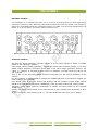
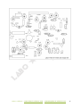
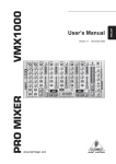
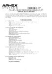
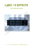
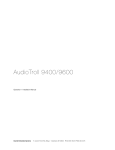
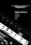
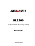
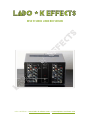
Neve 51 series LUNCH BOX VERSION Labo ★ K Effects – www.labo-k-effects.com – [email protected] contents CONTENTS 2 KEY FEATURES 3 OVERVIEW 4 PREAMPLI MODULE 5 DYNAMICS SECTION 6 EQUALISER MODULE 7 INTERCONNECTIONS 9 INTERNAL ADJUSTMENTS 9 Labo ★ K Effects – www.labo-k-effects.com – [email protected] 2 Key features 2 Neve 51 console channel strips revised and racked by Labo ★ K Effects. Connectors: Micro input balanced XLR 3 pins. Ligne input balanced XLR 3 pins. Insertion send balanced +4dB Jack 6,35 stereo. Insertion return balanced Jack 6,35 stereo. Output balanced +4dB XLR 3 pins. Power supply 220V AC. Optional removable Ears for fixation in 19 inches bay are available. Dimensions : 305x175x279.5mm Weigh: 7.8 Kg. This device must be plugged into a grounded outlet. Labo ★ K Effects – www.labo-k-effects.com – [email protected] 3 overview Description of modules is extracted from the Neve 51 service manual This device contains 2 preamplis + 2 equalizers from a NEVE 51 serie mixing desk. Each channel consists of one micro/line preampli, one high pass and low pass filter section. Each preampli module contains a Dynamics section featuring a limiter/gate. One 4-band parametric equalizer. One balanced +4dB insertion movable pre or post equalizer. One balanced +4dB output stage. Facilities : Mic gain range (switched) 0 to +80dB in 10dB steps. Mic gain (variable) ±10dB on Mic Trim control. Line gain, -12dB to +8dB switched in 2dB steps or potentiometer controled according to the version. Phase inversion facility. High pass filter 31Hz to 315Hz, adjustable 24dB/octave slope. Low pass filter 4KHz to 12.5KHz, 12dB/octave steps. Signal threshold. The indicator led lights when the signal level is above +4dB Threshold can be set differently using a trimmer inside the rack. « OD » switch wiring has been modified to allow the activation of the 48V power supply required for condenser microphones. A yellow Led indicates the presence of this power. Dynamics section gives the following facilities : « Soft Limit », « Hard Limit » and « Gate » facilities with threshold of each controlled by the « THRESHOLD » control. Fast or normal attack, linking of channels as indicated by the « -- » button. The Led shows limiting in progress. An internal power supply provides the voltages necessary for the operation of the modules. The AC input of the R-Core type transformer is protected by a fuse accessible from the outside. The provided regulated voltages are : 1) +/- 16v for audio parts. 2) -15v for logic and Leds. 3) +48v for phantom power. Modules have been recapped and defectives flex strips were replaced. Switches have been cleaned. All modules tested and adjustments have been done. Micro, Ligne inputs and channel outputs are wired on Neutrik XLR. Insertion sends and returns are wired on Cliff stereo Jacks. The pin assignment is as follows : XLR Hi Lo Gnd Pin 2 3 1 Jack Hi Lo Gnd Pin Tip Ring Sleeve Labo ★ K Effects – www.labo-k-effects.com – [email protected] 4 Preampli module Input section : 1) The microphone sensitivity control gives gain steps of 10dB. The front panel legend gives overall channel strip gain the signal is attenuated by -16dB by the input section so that a signal input of OdBu gives a pre-fade level of -16dBu. ·Positions 1,2 and 3 of the control switch in a 30dB pad which with the rotary control gives the required attenuation. This pad is bypassed by a relay for higher selected gains. The input transformer is configured to give a 12dB step-up ratio. When switching from 4 to 3 and vice versa (the pad changeover positions), the signal path is muted before the relay state is changed. 2) Line sensitivity control gives a -12dB to +8dB gain contol by 2dB steps (switched) or via a potentiometer according to the version. 3) Microphone Trim control gives a ±10dB trim of the microphone gain and has a logarythmic characteristic. 4) « LINE » switch allows to select input source, Micro or Line. 5) « PHASE » switch inverts phase of both Micro and Line signals. When pressed, the output is out of phase with the input and the phase Led lights. 6) « OD » switch cap is replaced by a red one. This switch allows (after Labo K’s mod) to activate the 48V phantom power. A yellow Led indicates the presence of this power. Filter section: When either filter is selected the filter LED is turned on. 1) High pass filter = 4 pole Butterworth without of band attenuation of 24dB/octave. 3 dB down point is marked on rotary control. 2) Low pass filter = 2 pole Butterworth (12dB/oct). 3 dB down point is marked on rotary control. Préampli Filtres Dynamics Labo ★ K Effects – www.labo-k-effects.com – [email protected] 5 Dynamics section There are three modes of operation : 1) Hard Limit « HL ». Limiter will not allow peaking value set above set ‘TRESH’ value. If the signal level exceeds the set value the gain of the circuit is reduced by the control side chain so that the level of the ouput signal equals the threshold set value. Once the side chain has been activated, the gain is restored under the control of the circuit time constants. The compression ratio of the Hard Limit mode is typically greater than 100:1. 2) Soft Limit « SL ». Module operates as a compressor/limiter, giving increasing compression with increasing signal over threshold. In this mode, the compression ratio gradually increases from 1.5:1 for an input signal amplitude equal to the threshold set level, reaching 100:1 for a signal 20dBs above the threshold level. 3) Noise Gate « GATE ». Module operates as a noise gate, reducing the noise floor by 15dB. In this mode the threshold is 50dB below that marked on the control. Signals below the threshold level set the path gain to -25dB. If the signal then increases a defined amount above the threshold the path gain reverts to OdB. This built in hysteresis prevents the gate switching indecisively for marginal signal levels and is approximately lOdBs. The GATE ON/OFF switching time constants are approximately 20mS to prevent audible 'Fourier' clicks. 4) THRESH. Sets the level at which the three circuit functions operate, with modification explained in point (3). 5) « FAST » switch. Pressing the button decreases an internal time constant by 10:1. This ratio is modified by the limiting mode selected, giving a resultant attack time ratio, with and without « FAST » selected, of 4 :1 with HARD LIMIT selected and 10 :1 with SOFT LIMIT selected. With both FAST and HARD LIMIT selected, he attack time is 250㎲. 6) « Arrow» switch. Allows the control sidechain of the circuit to activate the adjacent channel's DYNAMICS module, allowing 2 modules to be grouped together. The circuit is designed so that the highest control voltage of a group of linked units controls the group 7) IN. When selected the dynamics module is operative. When deselected the module may still activate the adjacent channel's control sidechain. 8) Limiting LED. This LED illuminates when there is a gain reduction through the module of 3dB or more. En Gate mode, Led lights off when the signal level is above the set threshold and gate opens. Signal presence / Overload indicator : Signal indicator is full wave rectified and the peak value of the input signal is stored. This voltage is compared with the voltage on the signal threshold input (set to 0dB by default) and if greater the SIG LED is turned on. Attack time = 2mS and release time = 1. 5 S approx. Labo ★ K Effects – www.labo-k-effects.com – [email protected] 6 Equalizer module Equaliser section : The equalizer is a 4-band type with mid 1 and mid 2 peaking and low and high bands peaking or shelving. Each band has adjustable frequencies and cut/ boost. The frequency bands are overlapping and the cut/boost range is ±17dBs. Low and high bands have a Q factor of 0.72 and mid 1 and mid 2 have a Q factor of 2. Insertion Equaliseur Insertion section : On Neve 51 series consoles, insertion section of mono input channel is fitted on 10882 board on the equalizer module. This board, named ‘Patch Interface’, carries two electrically separate stages. A Hi level VMOS output amplifier (Insertion Send) and a line input stage (Insertion Return). An extra +/- 25V psu is required by this circuit. In addition, insertion send and return are out of phase. This is due to the fact that phase inversion took place on the active patchbay of the console. For this reasons, it was decided to replace this 10882 board by a card that is suitable for rack mounting the modules. This board (Labo K Neve 51 Insert and Output) has an insertion output stage (Send) based on a high quality line driver (SSM2142) witch provides a balanced output +4dB. Insertion return stage (Return) meanwhile is exactly the same fitted on the original 10882 card. Finally, the buffer output stage of the channel and its gain setting were implanted on this board. All the circuits are now working with +/- 16v PSU and send and return are in phase. Labo ★ K Effects – www.labo-k-effects.com – [email protected] 7 Carte Labo K Neve 51 Insertion and Output Labo ★ K Effects – www.labo-k-effects.com – [email protected] 8 interconections To facilitate the implementation of these Neve 51 modules, interconnections boards have been developed. These cards use double sided plated through holes printed circuit boards (PCBs). To connect the preamp and EQ modules to these cards, originals flat cables of the channelstrips are used. This boards also allows PSU connections and distribute various voltages to modules. Finally, inputs and outputs connectors are also wired to the card. This allows to easily extract modules for possible maintenance. An output attenuator controlled by a potentiometer on front panel is connected between the buffer and the output stage of each channel. This potentiometer replaces the console fader. This allows to push the gain of the modules without saturating the input of the device wherein the rack is connected if the latter does not have the input setting. Internal adjustments Warning ! These settings should be performed by a qualified person. Output level : 1) 2) 3) 4) 5) 6) 7) Inject a 0dBm 1khz sinus signal in Line input. Plug a dB-meter on channel output connector. Set Line gain selector on 0dB. Set Trim pot on 0. Make shure that filters, equalizer and Dynamics are disabled. Set level pot on max if fitted. Adjust VR2 on Insert Out board (on the equaliser module) to read 0dBm on dB meter on the output connector. Signal indicator thtreshold : 1) Inject a 0dBm 1khz sinus signal in Line input. 2) Set Line gain selector on 0dB. 3) Adjust VR1 on 51 Input Interface board to make the signal led blink. It is possible to choose another threshold value than 0dB. Just apply the wished level to the input of the module and then adjust the trimmer VR1 as indicated higher. Remember ! The modules in this rack are vintage pieces. They are over 30 years old. Moisture, heat and smoke are the enemies of this unit. Labo ★ K Effects – www.labo-k-effects.com – [email protected] 9