1
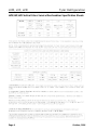
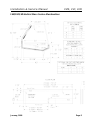
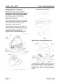
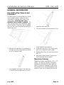
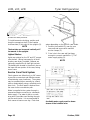
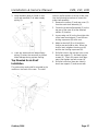
Installation & Service
Manual
LVM, LVF, LVD
VERTICAL GLASS MEAT/SEAFOOD/DELI MERCHANDISERS
Medium Temperature Service Display Cases
This manual has been designed to be used in conjunction with the General
Installation & Service Manual.
Save the Instructions in Both Manuals for Future Reference!!
This merchandiser conforms to the Commercial Refrigeration Manufacturers Association Health and Sanitation standard CRS-S1-96.
PRINTED IN Specifications subject to REPLACES
IN U.S.A.
change without notice. EDITION
1/97
ISSUE
DATE
7/99
Tyler Refrigeration Corporation * Niles, Michigan 49120
PART
NO.
9027529
REV.
B
LVM, LVF, LVD
Tyler Refrigeration
CONTENTS
Page
Specifications
LVM/LVF/LVD Specification Sheets . . . . . . . . . . . . . . . . . . . . . . . . . 4
Line Sizing Requirements . . . . . . . . . . . . (See General I&S Manual)
Pre-Installation Responsibilities . . . . . . . . . . . (See General I&S Manual)
Installation Procedures
Carpentry Procedures . . . . . . . . . . . . . . . . . . . . . . . . . . . . . . . . . 6
Case Line-Up . . . . . . . . . . . . . . . . . . . . . . . . . . . . . . . . . . . . . . . . 6
Trim Installation . . . . . . . . . . . . . . . . . . . . . . . . . . . . . . . . . . . . . . . 7
Plumbing Procedures . . . . . . . . . . . . . . (See General I&S Manual)
Refrigeration Procedures . . . . . . . . . . . . . . . . . . . . . . . . . . . . . . . 8
Temperature Control . . . . . . . . . . . . . . . . . . . . . . . . . . . . . . . . . . . . 8
Setting Electronic Thermostat (LVM/LVF) . . . . . . . . . . . . . . . . . . . . 9
Electrical Procedures . . . . . . . . . . . . . . . . . . . . . . . . . . . . . . . . . . 9
Electrical Considerations . . . . . . . . . . . . . . . . . . . . . . . . . . . . . . . . 9
Defrost Information . . . . . . . . . . . . . . . . . . . . . . . . . . . . . . . . . . . . 9
Defrost Control Chart . . . . . . . . . . . . . . . . . . . . . . . . . . . . . . . . . . . 9
Installation Procedure Check Lists . . . . (See General I&S Manual)
Wiring Diagrams . . . . . . . . . . . . . . . . . . . . . . . . . . . . . . . . . . . . . . . . . . 9
LV(M/F/D) Domestic & Export (50Hz) Case Circuits (6’ Cases) . . . 10
LV(M/F/D) Domestic & Export (50Hz) Case Circuits (8’ Cases) . . . 11
LV(M/F/D) Domestic & Export (50Hz) Case Circuits (12’ Cases) . . 12
Cleaning and Sanitation
Stainless Steel Cleaning Methods . . . . . . . . . . . . . . . . . . . . . . . . 13
General Information
Rear Sliding Door Removal and Installation . . . . . . . . . . . . . . . . . 15
Mezzanine Shelving . . . . . . . . . . . . . . . . . . . . . . . . . . . . . . . . . . . 15
Service Case Flush System . . . . . . . . . . . . . . . . . . . . . . . . . . . . . 16
Top Mounted Scale Shelf Installation . . . . . . . . . . . . . . . . . . . . . . 17
Page 2
October, 1996
Installation & Service Manual
LVM, LVF, LVD
Page
Service Instructions
Preventive Maintenance . . . . . . . . . . . . (See General I&S Manual)
Light Servicing . . . . . . . . . . . . . . . . . . . . . . . . . . . . . . . . . . . . . . 18
Ballast and Lighting Locations . . . . . . . . . . . . . . . . . . . . . . . . . . . 18
Fan Blade and Motor Replacement . . . . (See General I&S Manual)
Color Band and Bumper Replacement . (See General I&S Manual)
Parts Information
Operational Parts List . . . . . . . . . . . . . . . . . . . . . . . . . . . . . . . . . 19
Cladding and Trim Parts List . . . . . . . . . . . . . . . . . . . . . . . . . . . 20
TYLER Warranty . . . . . . . . . . . . . . . . . . . . . . . (See General I&S Manual)
The following Medium Temperature Vertical Glass Meat, Seafood and Deli Service Merchandiser models are covered in this manual:
MODEL
DESCRIPTION
LVM
6’, 8’ & 12’ VERTICAL GLASS GRAVITY COIL MEAT SERVICE MERCHANDISER
LVF
6’, 8’ & 12’ VERTICAL GLASS GRAVITY COIL SEAFOOD SERVICE MERCHANDISER
LVD
6’, 8’ & 12’ VERTICAL GLASS FORCED AIR DELI SERVICE MERCHANDISER
January, 1997
Page 3
LVM, LVF, LVD
Tyler Refrigeration
LVM/LVF/LVD Vertical Glass Service Merchandiser Specification Sheets
Page 4
October, 1996
Installation & Service Manual
LVM, LVF, LVD
LVM/LVF/LVD Vertical Glass Service Merchandiser
January, 1998
Page 5
LVM, LVF, LVD
INSTALLATION PROCEDURES
Carpentry Procedures
Case Line-Up
Before starting the case line-up, review the
store layout floor plans and survey the areas
where case line-ups are going to be installed.
Tyler Refrigeration
NOTE
A foam gasket is factory installed on one
end of the case. This gasket fits into a
groove on the adjoining case when cases
are pulled together. Do not depend on the
foam gasket alone to make a good seal!
WARNING
These cases are very heavy and require two
or more people to move and/or position
them. Improper handling of these cases
could result in personal injury.
3. Apply two heavy beads of caulking compound from the Filler Kit to the end of
case at dotted (. . .) and dashed (- - -)
lines. Proper caulking provides good
case refrigeration and sanitation.
1. Snap chalk lines where the front and rear
base rails of the case are to be located for
the entire line-up.
4. Remove shipping tape from color band
backer and bumper backer.
NOTE
Front and rear edges of base rails should
always be used to line-up cases. 6” shims
allow adjoining ends of cases to be
shimmed together.
2. Locate highest point on chalk lines as a reference for determining the number of
shims to be placed under the case base
rails. Position first case at highest point on
the chalk lines and shim case supports as
required. Check leveling across the top of
the case .
CAUTION
5. Push cases tightly together making sure
the pull-ups are aligned.
6. Add shims (1), as required, under the
adjoining case base rails (2). Check leveling at top of the case (3).
If the base of this case is not sitting evenly
on the floor, the case could warp when
loaded and possibly break the glass.
Page 6
October, 1996
Installation & Service Manual
CAUTION
LVM, LVF, LVD
Trim Installation
Do not drill or use other holes through the
case end for pull-ups. This may deform
the case end and could cause joint leaks
and/or poor refrigeration.
7. Position pull-up bolts and mounting hardware at pull-up locations (A, B, C and D).
Do not tighten any pull-up hardware until
all of it has been installed. Tighten all
pull-up hardware equally starting at point
A and finishing at point D. Do not overtighten.
All joint trim and mounting hardware is
shipped loose. Joint trim includes rear base
joint trim (1), rear lower joint trim (2), rear
upper joint trim (3), top joint trim (4), outer
and inner glass joint trim (5), compound tape
(6) and horizontal joint trim (7).
Horizontal joint trim covers gaps between the
cases. The trim is glued onto the shipping
cardboard. It is applied after running beads
of caulking on the edges of the cases. Sheet
metal screws or pop-rivets can be used for
additional securing.
NOTE
Compound sealing tape can be added to
inside surfaces of inner and outer glass
joint trim to make the trim level and even.
Glass joint trim pieces are secured to inside
and outside of the glass joint with compound
tape.
Patch end trim is shipped factory installed.
The compound tape has already been
installed under the trim. Check and/or trim
any exposed compound tape.
See “General I&S Manual” for bumper and
color band installation and alignment.
October, 1996
Page 7
LVM, LVF, LVD
Refrigeration Procedures
Tyler Refrigeration
THERMOSTAT BULB PLACEMENT
Refrigeration system and superheat
instructions can be found in the “General
I&S Manual”. Service case temperature
control information is listed below.
Temperature Control
The temperature of each case is controlled
with a thermostat and suction line solenoid.
One thermostat and one solenoid are
required for up to three cases.
The LVM and LVF cases use a gravity coil
with an electronic thermostat for improved
temperature control. LVD cases use a conventional mechanical thermostat.
Typical Service Case with Gravity Coil
Typical Service Case with Blower Coil
THERMOSTAT BULB MOUNTED
UNDERNEATH COIL
Page 8
In addition to the thermostat and suction solenoid, a suction stop EPR valve is required in
the suction line. The EPR valve acts as a low
pressure limit to aid in the overall temperature
control.
October, 1996
Installation & Service Manual
LVM, LVF, LVD
Setting Electronic Thermostat (LVM/LVF)
NOTE
1. Remove the four screws and cover from the
electronic thermostat.
The ballast box is located at the lower left
rear corner of the case. It houses ballasts
and terminal blocks.
2. Set the heating/cooling jumper blocks to
the “COOL” position.
3. Adjust the differential potentiometer marked
“DIFF” to 10°F (LVM) or 1°F (LVF).
4. Position the setpoint dial, on the front
cover, to 29°F (LVM) or 34°F (LVF).
5. Check the temperature cycles by suspending a thermometer in the same general
area as the thermostat probe. The temperature should cycle between 19°F and 29°F
(LVM) or 33°F and 34°F (LVF).
6. Replace the cover and secure with four
screws.
With the cooling mode selected, the differential
is below the setpoint. The relay will energize
and the LED indicator will illuminate when the
temperature reaches the setpoint (29°F or
34°F). When the temperature drops to the setpoint (29°F or 34°F) minus the differential setting (10°F or 1°F), the relay and LED indicator
will de-energize and refrigeration will stop.
Start the refrigeration system (note that the
LED indicator is illuminated) and allow the case
to cool. This allows the thermostat to cycle the
suction solenoid valve from open to close.
The settings above are specific to TYLER service cases with gravity coils only. Other applications will require different setpoints
Electrical Procedures
Electrical Considerations
CAUTION
Make sure all electrical connections at components and terminal blocks are tight. This
prevents burning of electrical terminals
and/or premature component failure.
October, 1996
Case Fan Circuit (LVD Only)
This circuit is to be supplied by an uninterrupted, protected 120V circuit. The case fan
circuit is not cycled on this case.
Fluorescent Lamp Circuit
LV(M/F/D) case lighting is supplied by T-8
electronic ballast lights. It is controlled by a
light switch in each case. The standard lighting is 1-row of T-8 canopy lights.
Defrost Information
See “General I&S Manual” for operational
descriptions for each type of defrost control.
Defrost Control Chart
LVM/LVF Defrost Option Settings
Defrost
Defrost Defrosts Duration
Type
Per Day
(Min)
Off Time
1
110
Term.
Temp.
-----
LVD Defrost Option Settings
Defrost
Defrost Defrosts Duration
Per Day
(Min)
Type
Off Time
1
60
Term.
Temp.
-----
Thermostats and sensors are shown on page
8 of this manual.
WIRING DIAGRAMS
ELECTRICIAN NOTE - OVERCURRENT
PROTECTION
120V circuits should be protected by 15 or 20 Amp
devices per the requirements noted on the cabinet
nameplate or the National Electrical Code, Canadian
Electrical Code - Part 1, Section 28. 208V defrost
circuits employ No. 12 AWG field wire leads for field
connections. On remote cases intended for end to
end line-ups, bonding for ground may rely upon the
pull-up bolts.
Page 9
LVM/LVF/LVD Domestic & Export (50Hz) Case Circuits (6’ Cases)
Page 10
January, 1997
LVM/LVF/LVD Domestic & Export (50Hz) Case Circuits (8’ Cases)
January, 1997
Page 11
LVM/LVF/LVD Domestic & Export (50Hz) Case Circuits (12’ Cases)
Page 12
January, 1997
Installation & Service Manual
LVM, LVF, LVD
CLEANING INSTRUCTIONS
WARNING
TYLER Refrigeration does not recommend
the use of high pressure cleaning equipment on service style cases!! The sealing
of front glass and end joints is critical in
these cases and high pressure cleaners
can penetrate and/or damage these seals.
Damaged seals allow water leaks and/or
air leaks that can cause poor case refrigeration.
CAUTION
• When cleaning this case, try not to introduce water into the case faster than it
can be carried away by the waste outlet.
• Always use a soft cloth or sponge with
mild detergent and water to clean the
front glass. Never use abrasives or
scouring pads to clean glass. They can
scratch and/or damage the glass.
See “General I&S Manual” for case cleaning
instructions. Stainless steel cleaning is covered in the following chart.
Stainless Steel Cleaning Methods
The cleaning data in the following stainless steel cleaning chart was supplied by AISI. The information was supplied by
Prime Metals Division, Alumax Aluminum Corporation.
TYPE OF CLEANING
CLEANING AGENT*
APPLICATION METHOD**
EFFECT ON FINISH
Routine cleaning
Soap, ammonia or detergent and water.
Sponge with cloth, then
rinse with clear water and
wipe dry.
Satisfactory for use on all
finishes.
Smears and fingerprints
Arcal 20, Lac-O-Nu, Lumin
Wash O’Cedar Cream
Polish, Stainless Shine
Rub with cloth as directed
on the package.
Satisfactory for use on all
finishes. Provides barrier film
Apply with damp sponge or
cloth.
Satisfactory for use on all
finishes.
Rub with damp cloth.
Satisfactory for use on all
finishes if rubbing is light.
Grade FFF Italian pumice,
whiting or talc
Rub with damp cloth.
Use in direction of polish lines
on No. 4 (polished) finish.
May scratch No. 2 (mill) and
No. 7 and 8 (polished) finishes.
Liquid NuSteel
Rub with dry cloth. Use a
small amount of cleaner.
Use in direction of polish lines
on No. 4 (polished) finish.
May scratch No. 2 (mill) and
No. 7 and 8 (polished) finishes.
Paste NuSteel or DuBois
Temp
Rub with dry cloth. Use a
small amount of cleaner.
Use in direction of polish lines
on No. 4 (polished) finish.
May scratch No. 2 (mill) and
No. 7 and 8 (polished) finishes.
Cooper’s Stainless Steel
Cleaner, Revere Stainless
Steel Cleaner
Apply with damp sponge or.
cloth.
Use in direction of polish lines
on No. 4 (polished) finish.
May scratch No. 2 (mill) and
No. 7 and 8 (polished) finishes.
Household cleaners (Old
Dutch, Lighthouse, Sunbrite,
Wyandotte, Bab-O, Gold Dust,
Sapolio, Bon Ami, Ajax or
Comet)
Rub with a damp cloth. May
contain chlorine bleaches.
Rinse thoroughly after use, if
left on surface, may lead to
corrosion.
Use in direction of polish lines
on No. 4 (polished) finish.
May scratch No. 2 (mill) and
No. 7 and 8 (polished) finishes.
Stubborn spots and
Allchem Concentrated
stains, baked-on
Cleaner
splatter, and other light
discolorations
Samae, Twinkle, or Cameo
Copper Cleaner
July, 1999
Page 13
LVM, LVF, LVD
TYPE OF CLEANING
CLEANING AGENT*
Tyler Refrigeration
APPLICATION METHOD**
EFFECT ON FINISH
Grade F Italian pumice, Steel Rub with a damp cloth.
Bright, Lumin Cleaner, Zud,
Restoro, Bon Ami, Ajax or
Comet
Use in direction of polish lines
on No. 4 (polished) finish.
May scratch No. 2 (mill) and
No. 7 and 8 (polished) finishes.
Penny-Brite or Copper-Brite
Rub with a dry cloth. Use a
small amount of cleaner.
Use in direction of polish lines
on No. 4 (polished) finish.
May scratch No. 2 (mill) and
No. 7 and 8 (polished) finishes.
Penny-Brite or Copper-Brite
Rub with a dry cloth.
Use in direction of polish lines
on No. 4 (polished) finish.
May scratch No. 2 (mill) and
No. 7 and 8 (polished) finishes.
Paste NuSteel or DuBois
Temp
Rub with dry cloth. Use a
small amount of cleaner.
Use in direction of polish lines
on No. 4 (polished) finish.
May scratch No. 2 (mill) and
No. 7 and 8 (polished) finishes.
Revere Stainless Steel
Cleaner
Apply with a damp sponge
or cloth.
Use in direction of polish lines
on No. 4 (polished) finish.
May scratch No. 2 (mill) and
No. 7 and 8 (polished) finishes.
Allen Polish, Steel Bright,
Wyandotte, Bab-O or Zud
Rub with a damp cloth.
Use in direction of polish lines
on No. 4 (polished) finish.
May scratch No. 2 (mill) and
No. 7 and 8 (polished) finishes.
Burnt-on foods and
grease, fatty acids,
milkstone (where swabbing or rubbing is not
practical)
Easy-Off, De-Grease-It, 4-6%
hot solution of such agents
as trisodium tripolyphospate,
or 5-15% caustic soda
solution
Apply generous coating.
Allow to stand for 10-15 min.
Repeated application may
be necessary.
Excellent removal, satisfactory
for use on all finishes.
Tenacious deposits,
rusty discolorations,
industrial atmospheric
stains
Oakite No. 33, Dilac, Texo 12,
Texo N.Y., Flash-Klenz,
Caddy Cleaner, Turco Scale
4368 or Permag 57.
Swab and soak with clean
cloth. Let stand 15 minutes
or more according to directions on package. Rinse
and dry.
Satisfactory for use on all
finishes.
Hard water spots
and scale
Vinegar
Swab or wipe with a cloth.
Rinse with water and dry.
Satisfactory for use on all
finishes.
5% oxalic acid, 5% sulamic
acid, 5-10% phospheric acid,
or Dilac, Oakite No. 33,
Texo 12 or Texo N.Y.
Swab or soak with a cloth.
Let stand 10-15 minutes.
Always follow with neutralizer
rinse, and dry.
Satisfactory for use on all
finshes. Effective on tenacious
deposites or where scale has
built up.
Organic solvents such as
carbon tetrachloride, trichlorethylene, acetone, kerosene, gasoline, benzene,
alcohol and chlorethane n.u.
Rub with a cloth. Organic
solvents may be flammable
and/or toxic. Observe all
precautions against fire.
Do not smoke while vapors
are present. Be sure area
is well ventilated.
Satisfactory for use on all
finishes.
Heat tint or heavy
discoloration
Grease and oil
*
Use of proprietary names is intended only to indicate a type of cleaner, and does not constitute an endorsement, nor is omission of any proprietary cleanser to imply its inadequacy. It should be emphasized that all products should be used in strict
accordance with instructions on package.
**
In all applications a stainless steel wool or sponge or fibrous brush or pad are recommended. Avoid use of ordinary steel
wool or steel brushes for scouring stainless steel.
Page 14
October, 1996
Installation & Service Manual
LVM, LVF, LVD
GENERAL INFORMATION
Rear Sliding Door Removal and
Installation
The sliding doors come installed from the factory in the door frame. These doors are
removable for cleaning and to aid in case
maintenance. NOTE: DO NOT FULLY
IMMERSE DOORS WHEN CLEANING. The
inner and outer doors are marked with labels
from the factory. If the doors are not labeled,
the inner door can be identified as having the
limiter stops on it.
clears the lower track (4).
3. Tilt out the bottom of the outer door (1) so
it can clear the lower track (4).
1. Remove the outer door (1) by sliding it to
the right end of the door frame (2) (within
an inch of being closed).
4. Lower the outer door (1) out of the upper
track (3) to remove it from the case.
5. Repeat steps 1 thru 4 to remove the inner
door (5).
6. Reverse the above steps to replace the
inner and outer doors (5 and 1).
Mezzanine Shelving
2. Firmly grasp both sides of the outer door
(1) and lift into the upper track (3) until it
July, 1999
Mezzanine shelves are available in 10” or 12”
widths. One level of shelving is optionally
available for LVM and LVF cases, while two
levels of shelving is available for LVD cases.
The shelves can be moved forward from the
mullions in two inch increments and can be
Page 15
LVM, LVF, LVD
Tyler Refrigeration
locked into three positions.
To install mezzanine shelving, position and
insert the mezzanine shelf (1) and captive
shelf brackets (2) into slots in the uprights (3).
NOTE
The brackets can be moved vertically at 1”
increments in the uprights.
Lighted Shelves
Lights are optional on the 10” and 12” mezzanine shelves. Wiring harnesses for all shelf
locations are factory installed. Ballasts are
optionally supplied for all shelf light sockets.
The ballasts are located in the electric box on
the lower left rear portion of the case, facing
rear of case.
varies depending on the specific case needs.
1. Position the manifold (1) near the rear
case wall and secure with manifold
anchor clamps (2).
2. Cut a hole in the case well just large
enough to connect manifold to ½” PVC
water supply piping (3).
NOTE
Service Case Flush System
Flush systems are offered only on LVF cases
to provide a convenient and effective means
of maintaining case cleanliness. The system
may be operated either manually by a hand
valve or automatically using a solenoid and a
time clock. The flush water is drained from
the case via the normal drain path.
Water is supplied to the system through a
pressurized water connection to a domestic
water supply. The water is fed to a nozzle
array which provides even flushing throughout the case interior. It is recommended to
flush cases at least once a day. Flush time
Page 16
A suitable water supply must be downstream of the isolation valve.
October, 1996
Installation & Service Manual
3. Install isolation valve (4) (hand or solenoid) and manifold (1) to water supply
piping (3).
LVM, LVF, LVD
rests on the flat portion of the top of the case.
Use the following instructions to mount the
scale shelf assembly.
1. Remove the screws (1) and rear cover (2)
from the scale shelf assembly (3).
2. Center the scale shelf assembly (3) on the
top rear of the case (4) at the selected
mullion (5) location.
3. Loosen wing nut (6) on the front right side
of the lower rear support (7) and the two
locking capscrews (8) at the rear.
4. Adjust scale shelf (3) to sit level from
front-to-rear and side-to-side. When the
shelf is level, retighten the wing nut (6)
and the two locking capscrews (8).
4. Caulk the area where the water supply
piping (3) enters the case well to prevent
water leakage during system flushing.
Top Mounted Scale Shelf
Installation
5. Drill pilot holes in the top two holes in the
lower rear support (7), and start top two
screws (9). Check for proper shelf alignment, then tighten top two screws (9).
6. Drill pilot holes thru lower two holes in
lower rear support (7) and secure with
The optional top scale shelf is mounted to the
mullion on the back of the case. The shelf
October, 1996
Page 17
LVM, LVF, LVD
lower two screws (9).
Tyler Refrigeration
Refrigeration recommends you order all
7. Replace rear cover (2) and screws (1) on
scale shelf assembly (3).
SERVICE INSTRUCTIONS
Light Servicing
component parts from its Service Parts
Depart-ment.
Ballast Installation
See “General I&S Manual” for T-8 lamp, fan
blade and motor (LVD only), and color band
and bumper replacement instructions.
Ballast and Lighting Locations
All light ballasts are located in the electric box
on the left end of the rear of the case.
In order to retain safety approval with
Underwriters Laboratory and the Canadian
Standards Association, the mounting of electrical components and interconnecting wires
must not deviate from the following instructions. Only qualified personnel are authorized
to install the accessory items. TYLER
Page 18
1. Remove cover from electric box (1)
located on the left rear side of the case.
NOTE
If tappit screws are not available, a starwasher should be used between the ballast and the heads of the screws.
2. Install required number of ballasts (2) in
electric box (1) with two screws (3)
each.
October, 1996
Installation & Service Manual
LVM, LVF, LVD
3. Identify and connect required wiring harnesses (upper, lower, etc...) to the ballast connectors (4).
4. Replace cover on electric box (1).
PARTS INFORMATION
Operational Parts List
Case Usage
Electrical Circuit
Case Size
Domestic
Export
115 Volt 60 Hertz
220 Volt 50 Hertz
6’
8’
12’
6’
8’
12’
Fan Motor (LVD)
5125532
5 Watt
5125532
5 Watt
5125532
5 Watt
5222975
5 Watt
5222975
5 Watt
5222975
5 Watt
Fan Motor Brackets (LVD)
5962269
5962269
5962269
5962269
5962269
5962269
Fan Blades (7” 25° 5B) (LVD)
5236974
5236974
5236974
5236974
5236974
5236974
Rocker Switch
5961377
5961377
5961377
5961377
5961377
5961377
Rectangular Outlet
5236335
5236335
5236335
5236335
5236335
5236335
T-8 Lamp Ballast
(canopy)(1-row)
5991029
5991029
5991030
9028437
9028437
9028438
(opt. canopy)(2-row)
5966635
5966635
5991030
9028439
9028439
9028438
(opt. front floor)
5991029
5991029
5991030
9028437
9028437
9028438
(opt. shelf)(per row)
5991029
5991029
5991030
9028437
9028437
9028438
Opt. 800MA Ballast (canopy)
5049140
5049140
5049140
5204859
5204859
5204859
T-8 Lampholder (canopy)
5232279
5232279
5232279
5232279
5232279
5232279
5092414
5092414
5092414
5092414
5092414
5092414
5614628
5614628
5614628
5614628
5614628
5614628
5614629
5614629
5614629
5614629
5614629
5614629
Suction Solenoid Valve
5191445
5191445
5191445
5231619
5231619
5231619
Thermostat (LVD)
5193888
5193888
5193888
5193888
5193888
5193888
Electronic Thermostat (LVM/LVF)5997588
5997588
5997588
5997588
5997588
5997588
(opt. shelf)
Opt. 800MA Lampholder
(telescoping)
(stationary)
January, 1997
Page 19
LVM, LVF, LVD
Check Valve (LVM)
5199417
Tyler Refrigeration
5199417
5199417
5199417
5199417
5199417
For information on operational parts not listed above contact the TYLER Service Parts
Department.
Cladding and Trim Parts List
Item
Description
6’
8’
12’
1
Screw
5619204(2)
5619204(2)
5619204(2)
2
Top Joint Trim
5239835
5239835
5239835
3
Inner/Outer Glass Joint Trim
5239840(2)
5239840(2)
5239840(2)
4
Tape, Compound
5615115
5615115
5615115
5
Bumper Retainer
9025052
9025058
9025061
6
Screw, Shoulder
9025833(12)
9025833(16)
9025833(24)
7
Color Band, Painted
9025232
9025233
9025234
8
Color Band Backer, Painted
9025979
9025980
9025981
9
Bumper Backer
--------------- color per order ---------------
10
Bumper
--------------- color per order ---------------
11
Upr. Frt. Cladding, Painted
12
9025129
9025130
9025131
Rivet
5104702(4)
5104702(5)
5104702(7)
13
Screw, Shoulder
9025833(6)
9025833(10)
9025833(12)
14
Lwr. Frt. Cladding, Painted
9025120
9025121
9025122
15
Kickplate
16
Screw
5183536(6)
5183536(6)
5183536(8)
17
Kickplate Support
9041329(3)
9041329(3)
9041329(4)
18
Screw, Binding
5100217(3)
5100217(3)
5100217(3)
19
LH End Close-off, Painted
9022468
9022468
9022468
20
RH End Close-off, Painted
9022467
9022467
9022467
21
Horizontal Joint Trim
5961362
5961362
5961362
22
Rear Base Joint Trim
5233638
5233638
5233638
23
Screw
5619204(4)
5619204(4)
5619204(4)
24
Rear Lower Joint Trim
5233635
5233635
5233635
25
Screw
5199134(4)
5199134(4)
5199134(4)
Page 20
--------------- color per order ---------------
July, 1999
Installation & Service Manual
July, 1999
LVM, LVF, LVD
Page 21