1
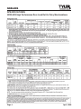
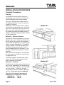
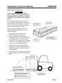
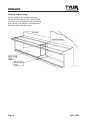
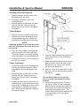
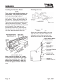
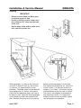
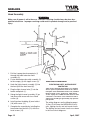
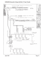
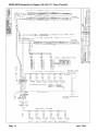
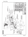
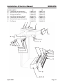
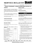
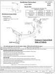
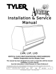
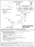
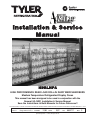
Installation & Service
Manual
NDRLHPA
HIGH PERFORMANCE REAR LOAD ROLL-IN DAIRY MERCHANDISERS
Medium Temperature Refrigerated Display Cases
This manual has been designed to be used in conjunction with the
General (UL/NSF) Installation & Service Manual.
Save the Instructions in Both Manuals for Future Reference!!
This merchandiser conforms to the American National Standard Institute & NSF International Health and Sanitation standard ANSI/NSF 7 - 2003.
PRINTED IN Specifications subject to REPLACES
IN U.S.A.
change without notice. EDITION
12/05
ISSUE
DATE
3/07
Tyler Refrigeration * Niles, Michigan 49120
PART
NO.
9052717
REV.
C
Installation & Service Manual
NDRLHPA
CONTENTS
Page
Specifications
NDRLHPA Specification Sheets . . . . . . . . . . . . . . . . . . . . . . . . . . . . . 4
Pre-Installation Responsibilities . . . . . . . . . . . . (See General I&S Manual)
Installation Procedures
Carpentry Procedures . . . . . . . . . . . . . . . . . . . . . . . . . . . . . . . . . . . 6
Planning . . . . . . . . . . . . . . . . . . . . . . . . . . . . . . . . . . . . . . . . . . . . . . 6
Unpacking and Placement . . . . . . . . . . . . . . . . . . . . . . . . . . . . . . . . . 7
Locating and Installing . . . . . . . . . . . . . . . . . . . . . . . . . . . . . . . . . . . . 8
Attaching Patch End Supports . . . . . . . . . . . . . . . . . . . . . . . . . . . . . 9
Ceiling Supports . . . . . . . . . . . . . . . . . . . . . . . . . . . . . . . . . . . . . . . . 9
Center Partitioning . . . . . . . . . . . . . . . . . . . . . . . . . . . . . . . . . . . . . . . 9
Installing Front Fan Panels . . . . . . . . . . . . . . . . . . . . . . . . . . . . . . . . 10
Finishing the Case . . . . . . . . . . . . . . . . . . . . . . . . . . . . . . . . . . . . . . 10
Shelving . . . . . . . . . . . . . . . . . . . . . . . . . . . . . . . . . . . . . . . . . . . . . 11
Hood Assembly . . . . . . . . . . . . . . . . . . . . . . . . . . . . . . . . . . . . . . . 12
Refrigeration Procedures . . . . . . . . . . . . (See General I&S Manual)
Installation Procedure Check Lists . . . . (See General I&S Manual)
Wiring Diagrams . . . . . . . . . . . . . . . . . . . . . . . . . . . . . . . . . . . . . . . . . . . 12
NDRLHPA Domestic & Export (50 Hz) 8’ Case Circuits . . . . . . . . . 13
NDRLHPA Domestic & Export (50 Hz) 12’ Case Circuits . . . . . . . . 14
Raceway Wiring . . . . . . . . . . . . . . . . . . . . . . . . . . . . . . . . . . . . . . . . 15
Cleaning and Sanitation . . . . . . . . . . . . . . . . . . . (See General I&S Manual)
Parts Information
Cladding and Trim Parts Lists . . . . . . . . . . . . . . . . . . . . . . . . . . . . 16
Operational Parts List . . . . . . . . . . . . . . . . . . . . . . . . . . . . . . . . . . 18
TYLER Warranty . . . . . . . . . . . . . . . . . . . . . . . . (See General I&S Manual)
The following High Performance Medium Temperature Rear Load Roll-In Dairy
Merchandiser models are covered in this manual:
MODELS
DESCRIPTION
NDRLHPA
8’ & 12’ HIGH PERFORMANCE REAR LOAD ROLL-IN DAIRY
MERCHANDISERS
April, 2007
Page 3
NDRLHPA
SPECIFICATIONS
NDRLHPA High Performance Rear Load Roll-In Dairy Merchandisers
Page 4
April, 2008
Installation & Service Manual
April, 2008
NDRLHPA
Page 5
NDRLHPA
INSTALLATION PROCEDURES
Carpentry Procedures
Planning
The cooler will need to be erected prior to
installing the cases. The cases can then be
raised and butted into the existing cooler.
The case is attached to the cooler and can
be supported by either structural suspension
supports or partitions.
Patch ends can be used on either a single 8’
or 12’ line-up to support the case. If you have
more than a single case you will need to use
either a one inch structural partition or a hanging support to provide the needed structural
support. Alternative hanging support methods
are described below.
Method #1
Method #1 - Structural Partitions
The one inch structural partition can be used
between every case, real load or front load, so
that the entire line-up will be self-supporting.
This method of supporting cases at every joint
satifies structural requirements. The problem
with this method is that later alterations may
|be difficult or not even possible. There is
also the added difficulty of alignment, as you
will have to depend much more on having a
level floor.
Rods tied into the ceiling joists and the top of
the case at each case joint can also be used
to support the case.
If structural partitions are to be used, make
sure to add 1 3/8” for each partition to the
total cut opening of the cooler.
Method #2 - Cantilever
Method #2
Cantilever beam systems project over the case
tops and are supported by two threaded rods
in each case end. A column is also to support
the case sections. The beams are to be
anchored at the rear to a suitable supporting
structure. Every joint must be supported.
To assist in the structural planning, the
NDRLHPA case weights are as follows:
NDRLHP-8A
NDRLHP-12A
Page 6
1250 lb
1450 lb
April, 2007
Installation & Service Manual
NDRLHPA
Unpacking and Placement
WARNING
Cases are heavy and require a lifting
device and two or more people to position
and support during installation. Improper
handling of cases could result in personal
injury.
Place pallet in the general area where the
case is going to be assembled. Remove all
the hold down and shipping braces from the
pallet. You will need a fork lift to raise and
support the case during installation.
Since the case is shipped inverted, it will
need to be flipped over before it can be
moved into place.
1. Remove the case end panels and
inspection plates from the case.
2. Place a standard 4 foot pallet with
cardboard on top of it on the floor behind
the shipping pallet. This pallet will be
used to raise and support the case during
installation. The cardboard prevents the
curtain track from being damaged.
3. Place material on the floor to prevent
damage to the case cladding during the
flipping and positioning of the case onto
the lifting pallet.
4. Using the fork lift and atleast two addition
people, flip the case over onto the lifting
pallet.
April, 2007
Page 7
NDRLHPA
Locating and Installing
Start installing cases at either end of the
line-up where the patch end is to be located.
If the case is to be supported from the ceiling
joists, lift the case into place and prepare to
attach the patch end to the case.
Page 8
April, 2007
Installation & Service Manual
NDRLHPA
Attaching Patch End Supports
1. Prepare the patch end by inserting the
ethofoam gasket into place.
2. Thoroughly caulk both sides of the
masonite spacer.
3. Attach the patch end with four 1/2” bolts
and one 3/8” bolt. Snug, but do not
tighten bolts until the case is completely
assembled.
Ceiling Support
1. Prop the case up in position with boards.
2. Prepare the case for adjoining by inserting the ethofoam gaskets in place and
prepare the masonite spacers with caulk.
NOTE
Adjoining sections of case must be next to
the each other before the center brace can
be inserted.
3. Place the center support in between the
two case sections and fasten with bolts.
The center support can now be attached
to the ceiling joists with the threaded rod.
4. Continue this process until all sections of
the case are in place.
Center Partitioning
1. Prepare the patch end for attachment by
inserting the ethofoam gaskets in place
and prepare the masonite spacers with
caulk.
2. Attach the patch end with four 1/2” bolts
and one 3/8” bolt. Snug, but do not
tighten bolts until the case is completely
assembled.
3. Prepare the other end of the case for the
center partition. Prop the end of the case
into position and prep the case end in the
same manner as you did for the patch
end. Make sure that the prop is holding
the case into place.
April, 2007
4. Place the center partition into position and
ready the adjacent case to be placed in
the line-up.
5. Lower pallet being held by the fork lift and
place the next case on the pallet as you
did the first case. Lift this case into the
line-up as you did the first.
6. Align the cases at the center joint and join
the cases with the attaching bolts found in
the filler kit.
NOTE
The five bolts shown are used to join
one case to the next through the center
partition.
7. Continue this procedure for all cases in
the line-up. When all cases have been
placed, remove the top cover of the case
and secure cases to the wall of walk-in
cooler with self-tapping screws. The
screws should be spaced at approximately one foot intervals to assure good
attachment.
Page 9
NDRLHPA
Installing the Front Fan Panels
Finishing the Case
NOTE
Floor anchors and mounting hardware are
not provided. The installer must provide
the required mounting hardware.
Install the 8’ and/or 12’ front fan panels with
floor anchors. All front fan panel braces are
located on the underside of the front panel.
The braces are located every four feet and at
the ends of the front fan panels. The front
fan panels may also be attached to the patch
ends, if desired. Floor stops are also
provided to keep the carts in position near
the front of the case. Install these after the
carts have been positioned in the case.
Attach the inside cooler end joints trim and
align the cases at the joints. Make sure to
thoroughly caulk at every case joint and
where the case meets the top of the cooler.
IMPORTANT NOTE
Make sure the cart wheels are straight
and the wheel stops keep the carts tight
against the front of the case. This will
prevent short circuiting of air flow and
maintain the proper air flows within the
case.
Page 10
April, 2007
Installation & Service Manual
NDRLHPA
Shelving
IMPORTANT
• Shelves must be fixed, not flip up type,
to maintain proper air flow.
• Product stacking in walk-in cooler must
be a minimum of 3’ away from the back
of the case.
• Service doors in the walk-in cooler must
have a positive gasket seal.
Shelving uprights (1) fasten to the overhead
structure (2) with 3/8” bolts (3), lockwashers
(4) and nuts (5) (when weldnuts are not
provided). The baffle needs only be removed
when uprights for 24” shelves are installed.
Holes into the supporting angles will have to
be drilled as well. When the shelving uprights
are full length, they must be secured to the
floor. Remove the wiring cover (6) to secure
April, 2007
bottom of shelving upright (1) to the floor,
then replace the wiring cover (6). Mount the
curtain carriers (7) to the back of the case
uprights (1) as shown. The curtains may be
mounted before or after the case is in place.
The curtains are weighted at the bottom to
help keep them closed. It is important to
keep the curtains closed to provide a good
seal and proper case operation.
Page 11
NDRLHPA
Hood Assembly
WARNING
Make sure all power is off to the case. Electrical servicing should always be done by a
qualified electrician. Improper servicing could result in product damage and/or personal
injury.
1. Pull the 3-prong female receptacle (1)
through the hood extension weld
assembly (2).
2. Fasten hood extension weld assembly (2)
to the canopy (3) with tappit screws (4).
3. Hook the light channel assembly (5) into
the front lip of the front hood (6).
4. Plug the light channel wire (7) into the
female receptacle (1).
5. Swing the light channel assembly (5) up
into place and secure with truss head
screws (8).
6. Install top front cladding (9) over ballast
(10) with screws (11).
7. Complete the assembly by installing the
hood extension joint trim (12) with truss
head screws (13).
Page 12
WIRING DIAGRAM
ELECTRICIAN NOTE - OVERCURRENT
PROTECTION
120V circuits should be protected by 15 or 20 Amp
devices per the requirements noted on the cabinet
nameplate or the National Electrical Code, Canadian
Electrical Code - Part 1, Section 28. 208V defrost
circuits employ No. 12 AWG field wire leads for field
connections. On remote cases intended for end to
end line-ups, bonding for ground may rely upon the
pull-up bolts.
The wiring diagrams on the following pages
13 thru 15 will cover the NDRLHPA case circuits, lighting circuits and anti-sweat circuits.
The lighting and anti-sweat circuits are shown
in the case circuit diagrams.
April, 2007
NDRLHPA Domestic & Export (50 Hz) 8’ Case Circuits
April, 2007
Page 13
NDRLHPA Domestic & Export (50 Hz) 12’ Case Circuits
Page 14
April, 2007
Raceway Wiring
April, 2007
Page 15
NDRLHPA
PARTS INFORMATION
Cladding and Trim Parts Lists
Item
1
2
3
4
5
6
7
8
9
10
11
12
13
14
15
16
17
18
19
20
21
22
23
24
Description
Screw (per close-off panel assy)
Close-off Panel Assembly
Screw (per top cover)
Top Cover
Opt. Short Hood Assembly, Ptd.
(NDRLHPA to N6D)
Std. Canopy Hood, Ptd.
Opt. Short Hood Joint Trim
Std. Hood Joint Trim
Screw (per hood joint trim)
Light Channel Joint Trim
Front Duct
Bumper Retainer
Shoulder Screw (per bumper retainer)
Color Band, Ptd.
Color Band Backer, Ptd.
Bumper Backer
Bumper End Trim
Bumper
Front Cladding, Ptd.
Screw
Raceway Cover
Raceway Cover Retainer
Screw (per retainer)
Raceway Cover End Trim
Raceway Cover Backer
Metal Kickplate, Ptd.
Kickplate Joint Trim, Ptd.
Kickplate Support
LH End Close-off
LH Top End Close-off
RH End Close-off
RH Top End Close-off
Electrical Junction Box (in assembly)
Junction Box Cover (in assembly)
Electrical Conduit (in assembly)
Nut (per end spacers)
Lock Washer (per end spacers)
Page 16
NDRLHPA
8’
12’
1309067 (9)
1309067 (12)
9026544
9026546
5183536 (5)
5183536 (10)
5186277
5186278
9605004
9602848
9025223
5222048
5222015
5205439 (6)
5222014
9053728 (2)
---- color
9025833 (16)
9023798
9025982
---- color
---- color
---- color
9301434
5183536 (9)
---- color
9023841 (4)
5183536 (2)
---- color
---- color
9324402
9324550
9039022 (6)
9053718
9053722
9053719
9053724
5102187
5102157
5102195
5100634 (2)
5101006 (2)
by
by
by
by
by
by
by
9025224
5222048
5222015
5205439 (6)
5222014
9053728 (3)
order ---9025833 (24)
9025119
9025982
order ---order ---order ---9301435
5183536 (12)
order ---9023841 (6)
5183536 (2)
order ---order ---9324407
9324550
9039022 (8)
9053718
9053722
9053719
9053724
5102187
5102157
5102195
5100634 (2)
5101006 (2)
April, 2008
Installation & Service Manual
Item
25
26
27
28
29
30
31
Description
Flat Washer (per end spacers)
Machine Screw (per end spacers)
Nut (per end spacers)
Lock Washer (per end spacers)
Flat Washer (per end spacers)
Machine Screw (per end spacers)
End Spacer
April, 2008
8’
5100979 (4)
5107443 (2)
5100643 (6)
5628631 (6)
5100982 (12)
5120913 (6)
5184602 (2)
NDRLHPA
12’
5100979 (4)
5107443 (2)
5100643 (6)
5628631 (6)
5100982 (12)
5120913 (6)
5184602 (2)
Page 17
NDRLHPA
Operational Parts List
Case Usage
Electrical Circuit
Case Size
Domestic
115 Volt 60 Hertz
8’
12’
Upper Fan Motor
9458939
16 Watt
9458939
16 Watt
Upper Fan Motor Brackets
5205112
5205112
Upper Fan Bracket Plate
9041007
9041007
Upper Fan Blades
(8.75” 30° 5B)
9407319
9407319
Opt. ECM Upr. Fan Motor
N/A
N/A
Opt. ECM Upr. Fan Bracket
N/A
N/A
Opt. ECM Upr. Fan Blades
N/A
N/A
Lower Fan Motor
5125532
5 Watt
5125532
5 Watt
Lower Fan Motor Brackets
5120098
5120098
9454640
9454640
5966635
5991030
5991029
5991030
T-8 Lampholder (canopy)
5232279
5232279
Light Switch (SPST)
5100565
5100565
Anti-Sweat Heater
(air grid retainer)
5124818
5124819
Lower Fan Blades
(7.75” 37° 5B)
T-8 Lamp Ballast (canopy)
(1st & 2nd row)
(3rd row)
For information on operational parts not listed above contact the TYLER Service Parts
Department.
Page 18
April, 2007