1
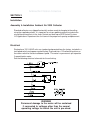
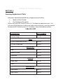
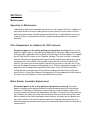
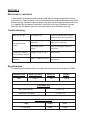
Installation & Service Manual
for
Ambient AIR 2000
Media Filtration Systems
February 19th, 2003
Ambient Air Filtration Collectors
Table of Contents
Disclaimer ....................................................................................................... 3
Uncrating ......................................................................................................... 4
Description & Operation ................................................................................. 4
Optional Equipment ........................................................................................ 4
Applications - General .................................................................................... 4
Installation ....................................................................................................... 5
Ordering Replacement Parts .......................................................................... 6
Maintenance .................................................................................................... 7
Maintenance continued ................................................................................... 8
Troubleshooting .............................................................................................. 8
Specifications ................................................................................................. 8
Limited Warranty ............................................................................................. 9
Ambinet Air Filtration Collectors
Disclaimer
Although instructions and recommendations are included for installation of your Ambient
Air Media Collector equipment, the manufacturer does not assume responsibility for the
installation of this equipment nor shall he be held liable for direct or consequential damages resulting from improper installation, application, maintenance or use.
The immense variety of contaminants make it impossible to list all of the potential hazards
that may be encountered with air pollution control systems. It is therefore important that the
application of the equipment be discussed with an AER Control Systems representative
or application engineer prior to use. Additionally, users should consult and comply with all
National and Local Fire, Electrical and /or other appropriate codes when determining the
application, location and operation of any air pollution control equipment.
Collection of combustible or explosive materials and collection on flame or spark-generating
operations may require specific system configurations (contact AER Control Systems
LLC. Applications Engineering Department for questions and/or design assistance). The
combined collection of combustible or explosive materials and contaminants from spark
or flame generating operations, with a common collector or duct system, is not recommended, unless special design provisions have been made to the system (sparks or
flames resulting from such operations may ignite the combustible or explosive material).
Under no circumstances should anyone be allowed to discard a lighted cigarette, other
burning materials, or refuse into an inlet hood or the duct of the collection system. It is the
responsibility of the end user to comply with all applicable national, state, and local fire
and safety codes.
This manual should be read completely before attempting Operation or Maintenance of
this equipment. All work should be performed by qualified personnel according to local
requirements.
WARNING
Failure to comply fully with the following instructions and local code
requirements may increase your risk of physical injury due to fire,
explosion or electrical shock.
All data and dimensions in this manual have been thoroughly checked however, we cannot
assume responsibility for possible errors or omissions. We reserve the right to change
designs and/or specifications without notice.
Ambient Air Filtration Collectors
SECTION 1
Uncrating
1.
Remove banding and cardboard shipping carton and packing.
2.
The Ambient Air 2000 unit is shipped in the horizontal position.
3.
Inspect the exterior of the unit and accesories for shipping damage or shortage
that may not have been noticed or recorded when the shipment was initially
received, you have 30 days to notify AER Control Systems LLC of any
decrepancies. Contact the shipping company if any damage or shortages have
occurred.
Description & Operation
The standard Ambient Air 2000 collector can either be mounted from the ceiling or wall.
The Ambient Air is an unducted collector designed to circulate the air inside a shop,
warehouse, or schools. Ambient Air has 2 stages of filtration, a 4 inch disposable
multi-vee filter and a disposable 10 pocket, 21 inch long 95% ASHRAE fiberglass Veebag. The standard blower is a forward curved centrifugal fan with a direct drive single
phase electric motor. The standard horsepower for the motor is 3/4 HP.
Optional Equipment
Wrap around prefilter
Inlet Flange
Side Exhaust Deflector
SECTION 2
Applications - General
1.
Dust - The Ambient Air 2000 collector is primarily designed for the capture and
removal of dust contaminants from a wide variety of manufacturing processes.
2.
Mounting options and accessories - The Ambient Air 2000 is standard with
mounting eyebolts on top of the unit for ceiling mount. The inlet flange option
improves the efficiency of an ambient system as the air is circulated inside of a
shop as it provides a larger capture zone for the inlet air and dust to be drawn
into the unit. The Wrap Around prefilter option is a good prefilter mounted to the
inlet of the unit for larger fibrous dust contaminants. The side exhuast deflector
turns the exhaust air from the Ambient Air 2000 unit to either side of the unit to
rotate the circulated ambient air in a shop.
Ambinet Air Filtration Collectors
SECTION 3
Installation
Assembly & Installation Ambient Air 2000 Collector
Standard collectors are shipped horizontally and are ready for hanging to the ceiling
using the supplied eye bolts. It is important to set up a good air pattern to circulate the
air and the contaminants in the shop. Contact our local rep or AER Control Systems
LLC Applications Department for assistance in the proper unit spacing and placement.
Electrical
Single phase 115 V, 60 HZ units are standard and prewired from the factory, included is a
two speed switch and a power cord with plug. Plug cord into a 115 volt outlet and turn on
the rocker switch for the desired blower speed . The motor is a permanent split capacitor
2 speed electric motor.
See the following electrical schematic for the unit wiring.
WARNING
Permanent damage to the motor will be sustained
if connected to voltages other than the normal
operating voltage for which the unit is pre-wired.
Ambient Air Filtration Collectors
SECTION 4
Ordering Replacement Parts
Information required for prompt delivery of replacement parts will be:
1.
Model and Serial Number
2.
Part Number and Description
Contact your local AER Control Systems LLC. Distributor for replacement parts. Use
either our toll free telephone number or our website www.aercontrolsystem.com to obtain
the nearest AER Control Systems LLC. Distributor’s name and telephone number.
1-866-265-2372
DESCRIPTION
PART NUMBER
Minihelic Gauge
1217-01
Filters
4 x 24 x 24 Multi-Vee PreFilter
1035-05
21 x 24 x 24 Vee-Bag
1039-07
Motor/Blower
Motor
1020-01
Blower Assembly
1021-01
Capacitator
1248-01
Electrical
Power Cord
1201-01
Switch
1249-01
Miscellaneous
Outlet Louvre
1084-01
Door Latches
1063-01
Ambinet Air Filtration Collectors
SECTION 5
Maintenance
Operation & Maintenance
Lubrication or other routine periodic maintenance is not required. All that is needed is an
occasional check of fasteners and a general visual check of the unit to make sure that
nothing has gone wrong. Periodic replacement of the filters is required when necessary.
Dispose of filters in accordance with local standards and procedures for the material
collected.
Filter Replacement for Ambient Air 2000 Collector
Disconnect power to the unit by pulling out plug before servicing. Access to Veebag filter support loops is accomplished by opening the side access door and removing
the bag hanger support bar from two hooks inside the top of the filter cabinet. The support
bar will slide out of the loops on the 10 pocket Vee-bag. The multi-vee filter is removed
from the inlet of the unit by pulling out the top of the filter and lifting up slightly over a lip on
the bottom of the filter cabinet. The eye bolts help to hold the multi-vee inside the filter
cabinet. The frame from the Vee-bag will slide out the same way as the multi-vee. Insert
the new Vee-bag with loops on the bag going in first. Slide the support bar through all 10
pockets on the Vee-bag and hang the bar on the hooks. Insert the multi-vee with the
airflow direction arrow pointing into the cabinet and drop the bottom of the multi-vee in
over the lip first. Gently push down on the top corners of the cardboard of the filter to push
the filter in past the eyebolts as these help hold the filter in place.
Motor Blower Assembly Replacement
Disconnect power to the unit by pulling out plug before servicing. The motor
blower assembly can be replaced and accessed by removing the exhaust outlet panel
with louver. The blower is bolted down to mounting rails inside the blower cabinet. Remove these bolts and remove the motor blower assembly. The motor has three mounting
legs that bolts the motor to the inlet side of the blower housing. Remove these bolts and
loosen the bolt on the hub of the blower wheel to remove the motor from the blower housing and to slide the shaft out of the blower wheel hub. A band or clamp holds the three
motor mounting legs onto the motor, loosen the clamp and slide the motor or clamp out to
separate them.
SECTION 5
Maintenance continued
A new motor will slide back into the band clamp, tighten clamp and position the three
motor mounts. Slide the motor shaft into the blower wheel hub and bolt down motor to the
blower housing. Position the blower wheel away from the inlet ring of the blower housing.
It is important that the blower wheel does not rub the inlet ring of the blower housing.
Manually spin the blower wheel to insure no interference to the blower housing.
Troubleshooting
Motor fails to start
Low airflow and/or
suction
No Power to Unit
Check for proper power at outlet
Check for loose wire connections
Blower is running
backwards
Check blower rotation. Switch the
yellow wire if necessary.
Low airflow and/or
suction
Check for blockage, replace or
clean filters
Damage or hole in filters
Contaminant blowing
out of collector exhaust
Replace filters
Motor/blower noise or
vibration
Check for wheel to ring
interference
Wheel is rubbing inlet ring
Specifications
The specifications below will give the important information for the Ambient Air 2000.
Nominal CFM
Main Filter Area
2000
Motor HP
74 sq. ft.
Weight
3/4
150 lb.
Filter Sizes (in.)
Multi-Vee PreFilter
4 x 24 x 24
FiberGlass Vee-Bag
21 x 24 x 24
Unit Dimensions (in.)
Depth
47.00 Long
Height
Width
24.00
24.00
Limited Warranty
AER Control Systems LLC warrants all products sold only to purchasers for use in business or for resale, against defects in workmanship or materials under normal use, for one
(1) year after the date of purchase from AER Control Systems LLC. Misapplication of the
product, decomposition by reaction or chemical action and wear caused by abrasion will
not constitute, or be considered as a defect. Warranty is void if the product has been
subject to damage, unreasonable use, neglect, improper service, improper installation, or
other causes not arising from defects in original materials or workmanship. Any part that
is determined to be defective in material or workmanship and returned to an AER Control
Systems LLC distributor or authorized service facility, as AER Control Systems LLC
designates, shipping costs prepaid, will be, as the exclusive remedy, repaired or replaced
at AER Control Systems LLC’s option. AER Control Systems LLC shall not be liable for
any incidental or consequential cost, expenses, or damages resulting from any failure,
defect, or malfunction of this product, liability is expressly disclaimed. AER Control Systems LLC’s liability in all events is limited to and will not exceed, the purchase price of the
product. Title and risk of loss pass to the buyer on delivery to the common carrier. If a
product is damaged in transit, the recipient MUST make note of the damage upon receipt
of the product and file a claim with the carrier. AER Control Systems LLC will make a
good faith effort for prompt correction or other adjustment, with respect to any product that
proves to be defective within the warranty period.
Collection of combustible or explosive materials and collection on flame or spark-generating operation any require specific system configurations (contact AER Control Systems
LLC’s Applications Engineering Department for questions and/or design assistance). The
combined collection of combustible or explosive materials and contaminants from spark
or flame generating operations, with a common collector or duct system, is not recommended, unless special design provisions have been made to the system (sparks or
flames resulting from such operations may ignite the combustible or explosive material).
Under no circumstances should anyone be allowed to discard a lighted cigarette, other
burning materials, or refuse into an inlet hood or the duct of the collection system. It is the
responsibility of the end user to comply with all applicable national, state, and local fire
and safety codes. AER Control Systems LLC’s liabiltiy for consequential and incidental
damage resulting from a fire or explosion is expressly disclaimed.
Installation of suitable overload protection such as a motor starter, according to NEC
guidelines, is required. Failure to provide proper overload protection will void warranty
coverage on electrical components in the system. (Combination motor starters with
fusible disconnect packages are available through your local AER Control Systems LLC
representative). To ensure optimum collector performance, always use AER Control
Systems LLC replacement filters.