1
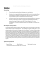
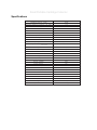
Installation & Service Manual
for
Small Portable
Cartridge Collector
Model
SPC-1000
March 16, 2006
Small Portable Cartridge Collector
Table of Contents
Disclaimer ....................................................................................................... 3
Uncrating ......................................................................................................... 4
Description & Operation ................................................................................. 4
Optional Equipment ........................................................................................ 4
Applications - General .................................................................................... 5
Installation ....................................................................................................... 6
Installation continued ...................................................................................... 7
Figure 1 Motor & Transformer Connection Diagram ...................................... 7
Figure 2 Control Timer .................................................................................... 8
Installation continued ...................................................................................... 9
Ordering Replacement Parts ........................................................................ 10
Maintenance .................................................................................................. 11
Troubleshooting ............................................................................................ 12
Specifications ............................................................................................... 13
Limited Warranty ........................................................................................... 14
Small Portable Cartridge Collector
Disclaimer
Although instructions and recommendations are included for installation of your Small Portable Cartridge Collector, SPC-1000, the manufacturer does not assume responsibility
for the installation of this equipment nor shall he be held liable for direct or consequential
damages resulting from improper installation, application, maintenance or use.
The immense variety of contaminants make it impossible to list all of the potential hazards
that may be encountered with air pollution control systems. It is therefore important that the
application of the equipment be discussed with an AER Control Systems representative or
application engineer prior to use. Additionally, users should consult and comply with all
National and Local Fire, Electrical and /or other appropriate codes when determining the
application, location and operation of any air pollution control equipment.
Collection of combustible or explosive materials and collection on flame or spark-generating
operations may require specific system configurations (contact AER Control Systems LLC.
Applications Engineering Department for questions and/or design assistance). The combined collection of combustible or explosive materials and contaminants from spark or flame
generating operations, with a common collector or duct system, is not recommended, unless special design provisions have been made to the system (sparks or flames resulting
from such operations may ignite the combustible or explosive material). Under no circumstances should anyone be allowed to discard a lighted cigarette, other burning materials, or
refuse into an inlet hood or the duct of the collection system. It is the responsibility of the end
user to comply with all applicable national, state, and local fire and safety codes.
This manual should be read completely before attempting Operation or Maintenance of this
equipment. All work should be performed by qualified personnel according to local requirements.
WARNING
Failure to comply fully with the following instructions and local code
requirements may increase your risk of physical injury due to fire,
explosion or electrical shock.
All data and dimensions in this manual have been thoroughly checked however, we cannot
assume responsibility for possible errors or omissions. We reserve the right to change
designs and/or specifications without notice.
Small Portable Cartridge Collector
SECTION 1
Uncrating
1.
Remove banding and cardboard shipping carton and packing.
2.
Extraction Arm is typically labeled and packed with the unit to be installed, Mount
ing hardware is included for mounting the arm. Be sure to check all boxes for
any miscellaneous parts or hardware items before discarding.
3.
Inspect the exterior of the unit and accessories for shipping damage or shortages
that may not have been noticed or recorded when the shipment was initially
received; you have 30 days to notify AER Control Systems LLC. of any
discrepancies. Contact the shipping company if any damage or shortages have
occurred.
Description & Operation
The Small Portable Cartridge Collector, SPC-1000 consist of a horizontally mounted filter
cabinet which houses the cartridge filter. The cartridge has a filter media pack of 3 inch
pleated media and is formed in the shape of a hollow cylinder. The interior of the cartridge
cylinder is open to the pulse tank module, which periodically cleans the cartridges by compressed air, pulse jet flushing. Diaphragm valve is mounted to a compressed air reservoir
tank and is activated by a manually controlled push button which opens the pulse valve for a
brief second. During operation a short blast of compressed air to the interior of the filter
results in media vibration and airflow reversal that back flushes collected contaminants off of
the exterior surface of the filter cartridge. The motor/blower cabinet is located on the clean
air side of the system after the pulse tank module and provides airflow for the collection
system.
Optional Equipment
Special Filters
Motor Starters
Various pulsing options including none or automatic
Mechanical Arm sizes
Small Portable Cartridge Collector
SECTION 2
Applications - General
1.
Dust & Fume - The Small Portable Cartridge Collector, SPC-1000 is designed
for the capture and removal of DRY dust and/or fumes generated from sanding,
grinding, welding and other industrial processes. The SPC-1000 cartridge
collector is a modular system with an extraction arm consisting of a filter media/
cartridge filter module, collection trays and a final module containing the air
reservoir tank and pulse-jet cleaning system, blower and motor. The unit can be
arranged in a variety of configurations and can be equipped with specialized
filters for application specific filtration requirements. Optional add-on filters are
available including HEPA, Activated Carbon for odors, and pre-filters.
2.
Size - It is important that the proper size unit has been selected for the application.
Too little airflow will not draw the contaminant into the filter and the unit will not be
completely effective. Too much airflow may result in loss of efficiency or the unit
will pick up large or heavy solid particles increasing the frequency of maintenance
or filter replacement. Questions regarding proper unit sizing should be directed to
your local AER Control Systems representative or the main office
(toll free 866-265-2372)
3.
Models - Model codes are utilized to identify the various unit configurations
available. The model SPC (Small Portable Cartridge) collector uses a direct
drive blower (sometimes called a plug fan) along with the number 1000. The 1000
unit has a 1.5 HP direct drive motor and has one cartridge filter.
4.
Dust Drawer - The removable dust drawer is required for dirt storage.
5.
Portable - The SPC-1000 has four casters for portability, two 10 inch rear wheels
and two 5 inch swivel front wheels.
Small Portable Cartridge Collector
SECTION 3
Installation
Assembly & Installation SPC-1000
Standard Collectors are pre-assembled for the SPC-1000 with the exception to the extraction arm. The assembly of the extraction arm consists of removing all the parts from the two
boxes, one box is the arm and the other is the hood.
1.
2.
3.
4.
5.
6.
7.
8.
Bend the arm out until the angle between the arms is 45 degrees.
Attach the end of the gas spring extension to the swivel base using two M6
Metric bolts, washers, and nuts.
Attach the other end of the gas spring to the tube using two M6 Metric bolts, wash
ers, and nuts.
Bolt the handle to the other tube using two M6 Metric bolts, washers, and nuts.
Attach the hood to both sections of the internal hood articulation arms using four
M6 Metric bolts and nuts.
Slide the hose ends onto the hood, both tubes, and swivel base and secure with
hose clamps.
Mount the swivel base to the surface you are bolting by using six M6 metric bolts,
washers, and nuts.
Adjust the tension of the arm.
The collector will be pre-wired to an ON/OFF switch and power cord for 115 volts 1 phase
(unless otherwise specified on the purchase order). Suitable overload protection is required
to protect the motor, a correctly sized circuit breaker is fine. Refer to the electrical section.
(Manual and Combination motor starters with fusible disconnect packages are available
through most local AER Control Systems LLC. and distributors).
A connection for clean, dry, compressed air is located outside the pulse tank module and
connected to the air reservoir tank. The supply airline should be purged to remove any debris before connecting it to the unit to prevent damage to the pulse valves on the system. The
supply compressed air line should be equipped with a manual shut-off valve, a filter/separator, air regulator, and a pressure gauge and located close to the SPC-1000 system. If the
unit is to be installed in an area where freezing temperatures or high humidity are to be
expected, an air dryer capable of drying the compressed air to below the dew point must
also be provided. If excessive moisture is present, check drain on the dryer frequently or
install an automatic drain.
Small Portable Cartridge Collector
SECTION 3
Installation continued
Electrical
The standard collector is wired for 115 volt, single phase with a switch and cord. Threephase units are wired for the input voltage specified on the purchase order. Unless specified otherwise, standard units are wired for 460 volt, 3 phase, 60 Hz operation.
Motors used on the SPC-1000 collectors are UL recognized and internal wiring is UL rated
at 600-volts. Input power line protection is required for the motor and electrical components.
Line load and current requirements are identified on the motor nameplate. Unless ordered
with the machine, the power switch for operating the machine, any fusible disconnect, motor
starter or controller are to be provided by the customer/user and located externally to the
machine.
After electrical hook up it is important to verify that the fan rotation is correct. Incorrect rotation results in much lower airflow and increased noise. For standard three phase installations, changing connections of any two of the three input power lines will usually reverse fan
rotation. Rotation direction can be found on the side and/or back of the motor.
If it becomes necessary to change the input voltage, the wiring diagram on the motor and
transformer nameplates show the appropriate wire connections - these diagrams are also
shown below:
Low Voltage
High Voltage
Low Voltage
6
5
4
6
5
4
8
5
9
8
7
9
8
7
3
4
3
2
1
3
2
1
1
2
Line
Line
Line
Interchange any two line wires to reverse rotation
3 Phase
Figure 1 - Motor Connection Diagram
NOTE
A motor starter with overload protection must be provided by the
User. Thermal overload heaters are installed in the external motor
starter. Consult the starter manufacturer for recommended heater
size for the installed motor.
Small Portable Cartridge Collector
Figure 2 - Optional Control Timer
Small Portable Cartridge Collector
SECTION 3
Installation continued
WARNING
Permanent damage to the motor will be sustained
if connected to voltages other than the normal
operating voltage for which the unit is pre-wired.
Control Systems
MANUAL CONTROLS for the SPC-1000 include an integrated, push button operated pilot
valve for the diaphragm valve. The compressed air tank and valve are fully enclosed and
located between the cartridge and the blower.
Compressed Air Requirements
Air reservoir pressure should be set between 90-psig (the minimum pressure which will
assure truly effective cleaning of the cartridges) and 105-psig (the maximum recommended
working pressure of the valves and air reservoir).
Note: The air reservoir system has a 120-psig-relief valve.
The total consumption of compressed air is variable and is dependent upon how often the
manual push button is depressed causing the diaphram valve to open and the air pressure
in the reservoir at the time of the air pulse. If the valve is opened for 0.1 second and the air
reservoir pressure is at 100-psig, approximately 0.9 cubic feet of free air will be used per
pulse. While the cartridges are being cleaned, the average usage rate in CFM of free air
depends upon the time in between the next pulse. If the valve opens at 30-second intervals
(2 pulses per minute) the average usage rate during a cleaning cycle would be (0.9 cu. ft./
pulse) x (2 pulses/minute) = 1.8 CFM of free air.
Small Portable Cartridge Collector
SECTION 4
Ordering Replacement Parts
Information required for prompt delivery of replacement parts will be:
1.
2.
Model and Serial Number
Part Number and Description
Contact your local AER Control Systems LLC. distributor for replacement parts. Use either
our toll free telephone number or our website www.aercontrolsystem.com to obtain the nearest AER Control Systems LLC. distributor’s name and telephone number.
1-866-265-2372
Par t Number
Description
Qty
1002-06
Motor 1.5HP 1PH 115V
1
1016-05
280 Wheel
1
1017-05
280 Cone
1
1043-11
Car tridge One End Open 15"L
1
1218-01
Diaphragm Air Valve 3/4"
1
1110-01
Pushbutton Relief
1
1089-01
Pressure Relief Valve
1
Small Portable Cartridge Collector
SECTION 5
Maintenance
Operation & Maintenance
Lubrication or other routine periodic preventative maintenance is not required. All that is
needed is an occasional check of fasteners, hoses and clamps and an overall visual check
of the unit . Periodic replacement of the cartridges is required when necessary. Always
empty the dust drawer before it fills completely. Do NOT allow the dust to collect to the point
where it begins to touch the bottom of the cartridge filter, since this would result in the dust
being re-entered into the air stream, re-depositing on the cartridge and shortening their life.
Cartridge Replacement SPC-1000
The pressure drop across the cartridge will eventually reach a point at which the airflow and
suction are too low. At this time, the cartridges should be replaced as follows:
1.
2.
3.
4.
5.
Shut off electrical power to the blower by unplugging the electrical cord.
Open the cartridge access door on the front of the filter cartridge module.
Slide the cartridges out on the rail by grabbing the cartidge and pulling it
toward you. Remove the cartridge for inspection or replacement.
Reinstall cartridge by sliding the cartridge into the cabinet on the rail.
Close the cartridge access doors.
Small Portable Cartridge Collector
Troubleshooting
Prob lem
Cause
N o Power To Unit
Check circuit b reaker fuses, rep lace
or reset if necessary. Check for
p rop er wire connections to and from
the star ter and collector (if
sup p lied).
Power to unit
Check wires from p ower cord and
switch on the collector to the motor.
Check motor wiring. Check to see if
motor is faulty.
Blower is running b ackwards
Check rotation of b lower. If running
b ackwards, interchange 2 of the 3
inp ut p ower leads (3 p hase motors
only). Single p hase switch wires 5 &
8.
Car tridges are not b eing cleaned
Check air p ulse system to see if it is
working correctly. Check air p ressure.
Ob struction in ducting
Check arm for b lockage. Check for
damp ers in the arm they may b e
closed. Imp rop er duct design.
Hole in the car tridge
Rep lace car tridge.
Car tridge not p rop erly installed
Check for correct car tridge
orientation. Check car tridge gasket,
gasket must seal around hole in
tub e sheet of car tridge cab inet.
Check car tridge access door, knob
should b e tight for p rop er door and
filter sealing
Motor Fails to Star t
Low air flow and/or suction
Solution
Contaminant b lowing out of the
collector exhaust
Check tub e to p ulse valve for leaks.
N o air p ulse when p ushb utton is
dep ressed.
Valve is leaking
Rep lace diap hragm valve seals or
valve.
N o p ower to timer b oard
Check for b lown fuses, rep lace if
necessary. Check transformer.
Power is getting to timer b oard
Check to see if comp ressed air is on,
and connected to unit. Check wiring
from b oard to valve assemb ly. Check
to see if valves are op ening.
N ot set p rop erly
Check timer set p oints. Off time b e
set for a longer p eriod than you
exp ect. Check high and low p ressure
set p oints on the Photohelic gauge.
High p ressure set p oint may b e set
too high.
Off time may b e set too shor t.
Check timer b oard settings, Timer
b oard is designed for p ulse intervals
every 8.5 sec to 3 minutes.
Set times on the Photohelic Gauge
op tion are not p rop erly set
High Pressure and/or Low Pressure
set p oints may b e set too low.
Unit is not p ulsing, b ut motor is
running (op tional timer)
Unit is not p ulsing, b ut motor is
running (units with delay timer or
Photohelic p ulse op tion)
Unit p ulses all of the time (op tional
timer)
Small Portable Cartridge Collector
Specifications
Sp eci fi cati ons
SPC-1000
N omi nal A i r fl ow - CFM
1000
A vai l ab l e External p ressure - IN . H2O
1-2
Fi l ters - Qty.
1
Total Fi l ter A rea - Sq . Ft.
150
Motor - HP
1.5
Motor Temp . Max - C
40
Comp ressed A i r
90-105 p si g
Tank Qty.
1
Tank Vol ume - Cu. Ft.
0.25
Di ap hragm Val ve
(1) .75 i n.
Program Ti mer: Off TIme
On Ti me
Manual - Pushb utton
Ti mer Inp ut Power
N /A
Bl ower/Motor Ty p e
Pl ug Fan
Inl et
1 std.
Dri ve
Di rect
Vol tage
115/230
Freq uency - Hz
50/60
Phase
1
Frame - N EMA
56C
Power Factor
85
Effi ci ency
70
Star t current A mp s (60hz)
50/25
Ful l Load A mp s (60hz)
16/8
Insul ati on Cl ass - mi n.
B
Encl osure
TEFC
Servi ce Factor
1.15
Duty Cy cl e
Conti nuous
Beari ng Grease
Exxon Pol y ex EM
Sp eci fi cati on
UL & CSA A p p orved
Limited Warranty
AER Control Systems LLC warrants all products sold only to purchasers for use in business
or for resale, against defects in workmanship or materials under normal use, for one (1) year
after the date of purchase from AER Control Systems LLC. Misapplication of the product,
decomposition by reaction or chemical action and wear caused by abrasion will not constitute, or be considered as a defect. Warranty is void if the product has been subject to damage, unreasonable use, neglect, improper service, improper installation, or other causes
not arising from defects in original materials or workmanship. Any part that is determined to
be defective in material or workmanship and returned to an AER Control Systems LLC
distributor or authorized service facility, as AER Control Systems LLC designates, shipping
costs prepaid, will be, as the exclusive remedy, repaired or replaced at AER Control Systems LLC’s option. AER Control Systems LLC shall not be liable for any incidental or consequential cost, expenses, or damages resulting from any failure, defect, or malfunction of
this product, liability is expressly disclaimed. AER Control Systems LLC’s liability in all events
is limited to and will not exceed, the purchase price of the product. Title and risk of loss pass
to the buyer on delivery to the common carrier. If a product is damaged in transit, the recipient MUST make note of the damage upon receipt of the product and file a claim with the
carrier. AER Control Systems LLC will make a good faith effort for prompt correction or
other adjustment, with respect to any product that proves to be defective within the warranty
period.
Collection of combustible or explosive materials and collection on flame or spark-generating operation any require specific system configurations (contact AER Control Systems
LLC’s Applications Engineering Department for questions and/or design assistance). The
combined collection of combustible or explosive materials and contaminants from spark or
flame generating operations, with a common collector or duct system, is not recommended,
unless special design provisions have been made to the system (sparks or flames resulting
from such operations may ignite the combustible or explosive material). Under no circumstances should anyone be allowed to discard a lighted cigarette, other burning materials, or
refuse into an inlet hood or the duct of the collection system. It is the responsibility of the end
user to comply with all applicable national, state, and local fire and safety codes. AER Control Systems LLC’s liabiltiy for consequential and incidental damage resulting from a fire or
explosion is expressly disclaimed.
Installation of suitable overload protection such as a motor starter, according to NEC guidelines, is required. Failure to provide proper overload protection will void warranty coverage
on electrical components in the system. (Combination motor starters with fusible disconnect
packages are available through your local AER Control Systems LLC representative). To
ensure optimum collector performance, always use AER Control Systems LLC replacement filters.