1
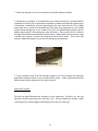
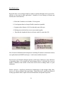
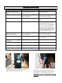
SERVICE MANUAL & USER GUIDE EZY2000PICKUPTRUCKLIFT EZY2000UTILITYLIFT EZY2000FLATBEDTRAILER TABLE OF CONTENTS INTRODUCTION ..……………………………………………………………………...……….. 1 PRODUCT IDENTIFICATION ……………………………………………………………….… 1 SAFETY ……………………………………………………………………………………………… 2 SAFETY LABELS …………………………………………………………………………………. 2-4 OPERATIONAL SAFETY ………………………………………………………………………… 5-6 OPERATING the Ezy-Lift™ SYSTEM ……………………………………………………….. 7-8 Ezy-Lift™ INSPECTION and MAINTENANCE ……………………..………………...…… 9 -14 TROUBLESHOOTING ………………………………………………………………………...…… 15 PARTS …………………………………………………………………………………….…………… 16 QUALITY SERVICE / CONTACT INFORMATION …………….……………………...…… 16 SPECIFICATIONS …………………………………………………………………………...……… 17 SCHEMATICS ………………………………………………………………………………………… 18 - 26 WARRANTY ……………………………………………………………………………………...…… 27 OWNER REGISTRATION……………………………………………………………………….. 31 INTRODUCTION PRODUCT IDENTIFICATION Using your Operator’s Manual Product Compatibility Read this entire Operator’s Manual, especially the Safety Information, before operating. This Manual is an important part of your machine. Keep all Manuals in a convenient location so they can be accessed easily. Use the Safety and Operating information in both the Ezy-Lift™ Operator’s Manual and the Machine Operator’s Manual to operate and service the unit safely and correctly. If your Ezy-Lift™ Manual has a section called “Preparing the Truck”, it means that you may need to do something additional to your truck before you can install the Ezy-Lift™ system. The Assembly and Installation sections of this Manual provide information to assemble and install the Ezy-Lift™ system into the cargo box of your vehicle. Refer to the Service section if any adjustments are required. If you have any questions or concerns with the assembly, installation or operation of the unit, contact your Ezy-Lift™ System Representative or Ezy-Lift™ CUSTOMER CONTACT CENTER: 1-800-974-3032 The Ezy-Lift™ System is compatible with truck vehicles of the following makes: Toyota Chevrolet/GMC Dodge Ford If you need to contact the Ezy-Lift™ Customer Contact Center for information on servicing, always provide the Product Serial Number and Date of Purchase. (Refer to Illustration below) Please locate the Product Serial Number and record all relevant information in the spaces below. DATE OF PURCHASE: _______________________________________________ DEALER NAME: _______________________________________________ DEALER PHONE: _______________________________________________ PRODUCT SERIAL NUMBER: ____________________________________________________ 1 SAFETY CAUTION READ THIS ENTIRE OPERATOR’S MANUAL BEFORE BEGINNING WORK ALWAYS WEAR SAFETY GLASSES AND USE CARE WHEN WORKING WITH POWER TOOLS Safety is a primary concern in the design and manufacturing of Ezy-Lift™ products. Unfortunately, all efforts to provide safe equipment can be totally negated by a single careless act by an Installer or Operator. Accident Prevention and Safety are dependent upon the awareness and proper training of the personnel who operate and maintain this equipment. The best safety device is a careful and informed Owner/Operator. Taking precedence over any specific rule, however, is the most important rule of all: SAFETY FIRST Ezy-Lift™ model 2000LBS™ lift system has a rated lift capacity of 905kg (2000 lbs) Maximum Hydraulic load capacity at full boom extension – 905kg (2000 lbs) Maximum Winch load capacity at full boom extension – 905 kg (2000 lbs) OVERLOADING YOUR VEHICLE CAN CAUSE POTENTIAL SAFETY HAZARDS! Read and obey all Safety Symbols, Warnings, Cautionary Notes and Operating Instructions on the Ezy-Lift™ and in this Manual. Ensure that all placards are in place and legible. Failure to comply with safety precautions in this Manual and on the Ezy-Lift™ is a safety violation that may result in serious injury, death or property damage. SAFETY LABELS Understanding Machine Safety Labels The unit’s Safety Labels, as shown in this section, are placed in important areas on your Ezy-Lift™ unit to draw attention to potential safety hazards. The Safety Labels on your unit are pictorial, ensuring they are most easily and universally understood. Where necessary, the Operator’s Manual explains any potential safety hazards in special safety messages identified with the words CAUTION or BE CAREFUL, and incorporate the Safety-Alert symbols shown below. AVOID INJURY Only trained personnel should be allowed to service or maintain the unit. Improper service or maintenance can lead to potential unit failure and injury while in use. 2 SAFETY LABELS (cont…) CAUTION BE CAREFUL CAUTION - KEEP HANDS AWAY BE CAREFUL This label is positioned on the lifting arms near the “pinch points” where the lift arms, unit frame and linkages converge, as well as on the lift arm hydraulic cylinders where they pass into and out of the lift frame. To avoid risk of serious injury it is essential to keep hands away from this area while the unit is in use. It is the responsibility of the Operator to advise others, including bystanders of this risk. NEVER remove the CAUTION label and replace immediately if missing. NEVER depend on the winch or wire rope to support a lifted load. NEVER stand or move under a lifted load. While operating the winch use a holding strap or tag line to maneuver the load. DO NOT grip the wire rope or the rope hook. It is recommended that leather gloves are used when rewinding the wire rope after use. 3 Please Note these Labels are Single Line 1,000 Lbs. and Double Line 2,000 Lbs. Max Lift Capacity Please Note these Labels are upside down to be read when boom arms are out. 4 OPERATIONAL SAFETY It is the Owner’s/Operator’s responsibility to use good judgment in the operation and maintenance of the Ezy-Lift™ Load Lift System. PLEASE READ THIS ENTIRE OPERATOR’S MANUAL BEFORE BEGINNING WORK It is the Owner’s/Operator’s responsibility to instruct and ensure that all Operators fully understand the safe operation and maintenance of the Ezy-Lift™ System. Anyone who operates the equipment must read and fully understand this Manual prior to operating the lift system. Failure to observe these instructions and safety procedures can result in serious injury and/or property damage. Train Ezy-Lift™ inspection and maintenance personnel for routine and periodic inspections and maintenance. Such training requirements should also provide information for compliance with any Federal, State and Local Code Requirements, existing Company safety rules and regulations and instructions furnished for the Ezy-Lift™ system. Because Ezy-Lift™, Inc. has no direct involvement or control over the operation and application of the Ezy-Lift™ System once it is installed on a vehicle, conforming to good safety practices is the responsibility of the Owner, the User, and its operating personnel. Therefore, it is essential that all personnel who will install, inspect, test, maintain and operate the Ezy-Lift™ unit, read and completely understand the contents of this Owner’s Manual. Only those authorized and qualified personnel who have shown that they have read and understood the Owner’s Manual and have understood the proper operation and maintenance of the Ezy-Lift™ System should be permitted to operate the Ezy-Lift™ System. General Safety Information READ and save all instructions. NEVER engage in any practice that will divert your attention while operating the Ezy-Lift™ System. NEVER operate the Ezy-Lift™ System from the Driver or Passenger seats. ALWAYS disconnect the Ezy-Lift™ Controller and cable from the receptacle when moving the vehicle. NEVER overload. Overloads can cause damage and create unsafe operating conditions. Ensure that the rated load capacity of any sling, lifter or fitting is not exceeded. Learn to use the Ezy-Lift™ System correctly. Take time to practice so that you are comfortable with the operating system. Maximum Hydraulic load capacity at full boom extension – 905 kg (2000 lbs) Maximum Winch load capacity at full boom extension – 905 kg (2000 lbs) NEVER handle the wire winch cable with bare hands ALWAYS use leather gloves when handling the winch cable. NEVER allow children or unauthorized personnel to operate the Ezy-Lift™ System at any time. NEVER use the unit for lifting, supporting or transporting people. NEVER stand beneath the load or Ezy-Lift™ System lift frame or use over areas where people are present. NEVER operate the Ezy-Lift™ System with Driver or Passenger in the vehicle. 5 OPERATIONAL SAFETY (cont…) General Safety Information (cont…) NEVER operate the Ezy-Lift™ System when someone is within an unsafe distance (clear of moving components). NEVER lift a load with a weight exceeding 905 kg (2000lb). Maximum Hydraulic load capacity at full extension – 905 kg (2000 lbs) Maximum Winch load capacity at full extension – 905 kg (2000 lbs) NEVER lift anything with the Ezy-Lift™ System while the truck is on an incline or side of hill. NEVER lift anything into the bed that will not fit, cause the vehicle to be unstable when driven or that cannot be safely secured as to not move around when transported. USE CAUTION - keep people, pets and property clear of the path of the load - keep work area clear and free of obstructions. DO NOT use for supporting an unattended load. DO NOT use for towing other vehicles. Before Operating Visually inspect the hook, snatch block, rope, hoist and accessories for any damage or wear. Reject rope or nylon slings with abnormal wear, torn stitching, broken or cut fibers or discoloration or deterioration. Reject rope with kinking, crushing, bird-caging, cuts or other distortions, evidence of heat damage, deformation or worn end attachments (hooks and snatch block). Ensure that the truck cargo bed and suspension system are in good condition; i.e. shocks, springs etc. Check to see that all fasteners are secure and that the gusset screws are all tight. Check for any evidence of hydraulic fluid leaks. NEVER MOVE THE TRUCK WITH A SUSPENDED LOAD 6 OPERATING the Ezy-Lift™ SYSTEM Your Ezy-Lift™ System operates from the truck’s 12-volt battery, which provides power to the winch and the hydraulic power unit. The hydraulic unit is completely self-contained with a DC motor, gear pump, reservoir, load hold check valves and relief valves to prevent overloading. Flow from the pump to a pair of double acting cylinders provides the lift and rotation necessary to extend and retract the lift arms via the hand-held remote control. USING THE UNIT UNDER LOW VOLTAGE CONDITIONS CAN REDUCE LIFE OF THE HYDRAULIC PUMP AND WINCH OPERATING INSTRUCTIONS STEP 1: Position your truck to allow the entire loading or unloading operation to be performed without having to move the vehicle. Ideally the truck will be on solid, level ground. Ensure that there is adequate overhead clearance for the lift arms to operate and extend fully. Maximum Hydraulic load capacity at full boom extension – 905 kg (2000 lbs) Maximum Winch load capacity at full boom extension – 905 kg (2000 lbs) STEP 2: Set the truck parking brake and leave the engine running so as not to discharge the battery. STEP 3: Open the truck tailgate - very important to prevent damage to the truck’s tailgate In some instances it is preferable to remove the tailgate prior to loading cargo. STEP 4: Plug the remote control assembly into the power/control jack that is located on the Driver’s side, near the base of the tailgate opening. STEP 5: Turn the Main Switch to the ON position. THE UNIT IS NOW READY FOR OPERATION. The Remote Control unit has two rocker buttons; one for the boom and one for the hoist. Each button is double acting with the following commands: BOOM IN, BOOM OUT, HOIST DOWN and HOIST UP. To activate the lift arms, press and hold the BOOM OUT control button. This will cause the arms to rise from their parked position and rotate out approximately 150°over the truck bed. To reverse the process and return the lift arms to their parked (down) position, press and hold the BOOM IN control button until the arms are fully down. Similarly, to activate the crane winch, press and hold the HOIST DOWN control button to lower (unwind) the wire/hook and the HOIST UP control button to raise (wind) the wire/hook. Both the lift arms and the crane winch can be stopped in any position by simply releasing the control button. Practice moving the arms in and out, raising and lowering the wire cable, and become comfortable with operating the system. Attaching a small load or providing tension to the winch hook when raising and lowering the wire cable will help keep the wire cable tightly wound on the drum. Make sure that the wire winds evenly across the entire surface of the winch drum. STEP 6: Now that you are familiar with the controls, press and hold the BOOM OUT control button to raise the lift arms and position them over the object to be lifted. Ensure that the winch is positioned directly above the center of the load to be lifted in order to prevent the load from swinging as it is hoisted from the ground. NOTE: A swinging load could cause injury and/or property damage. For large objects it may be necessary to remove the truck tailgate in order to correctly position the winch above the load. Failure to do so may cause damage to your vehicle and/or cargo box. 7 OPERATING the Ezy-Lift™ SYSTEM OPERATING INSTRUCTIONS (cont…) STEP 7: With the lift arm and winch now centered over the load, press and hold the HOIST DOWN button to lower the wire cable’s hoist hook into position for attaching to the load. Keeping tension on the wire cable while it unwinds will prevent slippage of the wire cable once the load is attached. NEVER WRAP THE LIFTING CABLE AROUND THE LOAD Use a nylon sling or metal chain to attach the hook to the load. Wrapping the wire cable around the load and hooking it back onto itself can damage the cable and create a potential safety hazard. NEVER ATTACH a sling or chain link to the tip of the lifting hook or attempt to lift a load from the tip of the hook. Make sure that the nylon sling or chain is properly seated in the saddle of the hoist hook. STEP 8: With the load now attached, press and hold the HOIST UP button. Slowly take up slack in the wire cable until it becomes taut. Keep tension on the wire cable during this process and make sure that the cable winds evenly across the drum. STOP - Recheck all lifting connections before proceeding to lift the load. STEP 9: When sure that all the lifting connections are secure, depress the HOIST UP button to slowly lift the load from the ground just high enough to clear the truck tailgate. DO NOT PULL FROM ANGLES as this can damage the lift arms. Continuous pulls at angles will also cause the wire cable to pile up at one end of the winch drum. This can jam the wire cable and damage the winch and/or cable. ALWAYS MAINTAIN at least five (5) wraps of wire cable on the winch drum, otherwise the wire cable drum fasteners will not withstand the load. STEP 10: Press and hold the BOOM IN button to move the load onto the truck bed. Use the HOIST DOWN button to keep the load low during the process. Once the load is at the desired position, release the BOOM IN button to stop the lift arms. STEP 11: Slowly lower the load onto the truck bed by pressing and holding the HOIST DOWN button. Once the load is resting safely in the truck bed, disconnect the wire cable’s hoist hook from the load. STEP 12: Depress the HOIST UP button to rewind the wire cable onto the winch spool. DO NOT OVERWIND as this could damage the winch and/or wire cable. Apply tension to the winch cable to ensure that it winds evenly and smoothly onto the winch spool. STEP 13: Return the lift arms to their parked position using the BOOM IN button. STEP 14: Turn the Main Switch to the OFF position. STEP 15: ALWAYS REMOVE the remote control from the power jack and store it in a clean, dry location to avoid damage while transporting the load. To prevent unauthorized use of the unit, NEVER leave the truck unattended with the remote control inserted into the power jack. PLACE THE REMOTE CONTROL IN A SAFE, SECURE LOCATION WHEN NOT IN USE 8 Ezy-Lift™ INSPECTION & MAINTENANCE Your Ezy-Lift™ System is designed to give years of faultless operation. However, as with any mechanical product, periodic inspection and maintenance is required to keep the unit in its best operating condition. Here are a few tips that Owners/Operators should periodically perform to keep the unit in top condition. PLEASE REVIEW THIS INFORMATION 1012 Second Street Anacortes, WA 98221 If you have any questions please contact Ezy-Lift™ during normal business hours, Central Standard Time, USA Telephone: 360-293-8488 Monday through Friday - excluding holidays. Fax: 360-293-8480 www.psrope.com 1012 Second Street Synthetic Rope email: [email protected] Anacortes, WA 98221 USA Telephone: Wire cable consists of a core, strands, and wires. The wire cable fits and wraps onto grooves on360-293-8488 the Second Street Fax:1012 360-293-8480 circumference of the winch drum that transmits motion to the wire cable. Wire cablewww.psrope.com sizes are stated the USA Anacortes, WAas 98221 Telephone: diameter of a circle that would enclose the wire cable strands; i.e. 8mm, 9.5mm (5/16”, 3/8”), etc. 360-293-8488 Each email: [email protected] Fax: 360-293-8480 wire cable size is available in various cable constructions and materials. www.psrope.com Inspection Guidelines for Plasma® Synthetic Ropes email: load,[email protected] a loosely Routinely check that the snythetic rope has not become loosely wound. Under wound spool allows the rope to work its way down into the layers of rope on the drum. This can Puget Sound Rope Company cause the rope to become wedged within the body of the windings on the spool and damage the ® Inspection Plasma Synthetic synthetic rope. Keep Guidelines tension on thefor rope during unwinding and Ropes rewinding. A good practice is to inspect and rewind the rope under tension after each use. ® Puget Sound Rope Company Inspection Guidelines for isPlasma Synthetic Ropes Routinely check to see that the rope cable evenly wound on the drum and not bunched to one side of the winch drum. During winding of the wire cable check to see that the rope is winding Puget Sound Rope Companyapplications for many years. Plasma evenly ropes have been usedIf necessary extensively in numerous on the drum. rewind the ropediverse under tension making sure that the cable is Over this time placed period,across particular conditions and hazards have been identified which evenly the operating width of the winch drum. are more harmful to Plasma than to steel. The presence of these conditions can best be Routinely check the rope for evidence of kinking or damage. determined byhave periodic inspection of the lines. This guideline presents recommendations for Plasma Replace ropes in numerous diverse applications for many years. anybeen rope used foundextensively to have evidence of kinking or damage. conducting periodic inspection the end user Over this time period, particularbyoperating conditions and hazards have been identified which Loosely woundharmful spool ortorope, wound at one end ofThe the hoist drum, it to become wedged are Plasma more Plasma than to steel. presence ofallowing theseapplications conditions canmany best years. becan ropes have been used extensively in numerous diverse for damage the rope and could cause it to break under load resulting in the potential for both property determined periodic inspection the lines.conditions This guideline presents recommendations Over thisbytime period, particularofoperating and hazards have been identified for which damage and injury. conducting periodic inspection by the end user are moreto harmful to in Plasma to steel. The presence of these conditions can best be Conditions be avoided Plasmathan Lines Frayingdetermined and kinkingby reduces theinspection load capacity of lines. the rope. Replace the presents recommendations for periodic of the This guideline conducting periodic ifinspection by the end user synthetic rope immediately either condition is found. When replacingto the rope, be sure to insert the attaching Conditions besynthetic avoided in Plasma There are three areas where close Lines attention needs to be paid to Plasma lines. Below are end of the wire cable into the correct end of the drum hole (See descriptions of these conditions and likely signs of their presence. Page 10Conditions on rope replacing). to be avoided in Plasma Lines After rope is pulled through, tie a knot to secure rope. Extra rope There are three areas where close attention needs to be paid to Plasma lines. Below are lay on drum and then tighten rope on drum by pushing in button on descriptions of these conditions likely signsedges. of theirWhile presence. 1. Repeated abrasion and against sharp HMPE is one of the most cutcontroller over ropelateral on drum. There are three areasavailable, where close attention needs to stronger be paid than to Plasma lines. Below are resistant polymers metal can prove to be Plasma in a longof these conditions andofbreak likely signs of their presence. Always descriptions use a synthetic rope event. with minimum duration abrasion Signs excess abrasion strand pullouts, strength at leastinclude 3,628 kg (8000 lbs). heavy 1. of Repeated lateral abrasion against sharp edges. While HMPE is one of the most cut- fuzzing and cut strands in a single resistant polymers available, metalarea, can prove to be stronger than Plasma in a longduration abrasion event. Signs of excess 1. Repeated lateral abrasion against sharp edges. While HMPE is one of the most cutnoted normal lightavailable, fuzzing the through abrasion include strand pullouts, heavy polymers metal can prove to hands. be stronger than Plasma in a longDo resistant notthat allow the synthetic rope toof slide bare Plasma rope surface is to be expected in fuzzing and cut strands in a single area, duration abrasion event. Signs of excess normal use. include This light fuzzing does not and localized bunching. It pullouts, should beheavy abrasion strand reduce the normal rated strength ofinthe line, 9 noted that light fuzzing of theand fuzzing and cut strands a single area, actually creates a protective layer on the Plasma rope surface is to be It expected in and localized bunching. should be ropenoted thatuse. helps to prevent further damage. normal This light fuzzing does not that normal light fuzzing of the reduce the rated strengthisoftothe and in 9 Plasma rope surface be line, expected remember to use heavy leather NOTE: Always and localized bunching. It should be gloves when handleing synthetic rope 2. Plasma begins to lose strength above about 160 ºF, and has a zero-strength temperature around 250 ºC. Signs of high temperature damage include, melting, fused strands, and significantly reduced diameter. The fused strands should not be confused with high-tension compression of the rope which might appear similar. With standard urethane coatings, the rope can appear melted after high tension has been applied while the rope is bent around a surface. This is normally not melting and can be worked out with little effort. The rope strength is not affected. 3. Plasma lines can lose strength if overstrained. This can be the result of exceeding the recommended design factor for an extended time period, or by instantaneous peak loads during dynamic loading events. A typical design factor is 5:1, but this should be determined in conjunction with the application engineer. Signs of overstraining can be subtle but include localized thinning and elongation, and loss in flexibility (for example the rope becomes rigid). Inspection Guidelines for Plasma Rope Below are some suggestions for inspecting Plasma for the above damage conditions. Each end user should develop their own method of routinely inspecting these lines for damage prior to heavy use. The method and frequency of inspection will depend on the end users experience and usage level. 1. Lay rope out under hand tension so the entire length can easily viewed. 2. Visually inspect the entire length of rope for signs of abrasion, heavy fuzzing, stiff regions, fused or melted regions or thinned areas. Make note of any damaged areas. 10 3. Relate any damage to service over hardware for possible situation remedies. 4. Monitor for overloading. To accomplish this, put a small (less than 10% of break load) but repeatable load on the line. In subsequent inspections a similar load should be applied again, so determine a method that will give approximately the same load each time. Put a bright mark on the line at a point just beyond the tail of the splice (one suggestion is to use a bright colored ribbon through one or two strands of he rope). Put another bright colored mark (or ribbon) approximately 20 feet down rope from first mark. ). These marks will be a reference for future measurements and should be located securely. While under reference tension, using a flexible tape measure, measure the length between reference marks. Write down this reference length and compare it to previous or subsequent measurements. 5. Keep a detailed record of the line reference length as well as any damage areas and their approximate locations relative to one or both reference marks. Future inspections should be used to monitor minor damage areas for signs of growth. Inspection Frequency The end user should determine the frequency of rope inspections. For heavy use, the rope should be carefully inspected prior to each day’s use. The user should also perform a quick visual inspection (without length measurement) prior to any use of the rope. 11 Rope Replacement: Ropes that show severe damage should be replaced, repaired (damaged areas cut out and respliced), or down-rated to other applications. Examples of severe damage in Plasma rope include (but are not limited to): a. More than 2 strands severed within a 2-foot segment b. Fused segment that is no longer flexible (strands not separable) c. Segment whose diameter is 20% less than other part of the rope d. Melting on one side that fuses one or more strands together e. Rope that has lengthened (between reference marks) by more than 10% Note: It has been found that cleaners/degreasers containing d’Limonene (citrus based cleaners) can rapidly deteriorate HMPE based ropes. Avoid contact with this chemical. Each end user will determine through experience which signs of damage are more indicative of impending failure. (For example, the critical damage mode of a rope that fails in service might be identified if the location of the break can be traced to damage noted in a prior inspection.) Plasma represent a significant technological breakthrough in high strength lifting lines; however, as with any synthetic fiber rope product, Plasma lines have a much better chance of meeting expectations when coupled with careful maintenance and periodic inspection. 12 PLASMA 12STRAND Plasma12strandisthehigheststrengthsyntheticropeavailable.Plasma12strandis manufacturedfromHoneywellSpectraFiberthathasbeenenhancedbyPugetSoundRope’s patentedrecrystallizationprocess.Thisprocessisespeciallyeffectiveinmediumtolargediameter ropeswherestrengthsareover50%higherandcreepissignificantlylessthanthatofstandard Spectra12strand. Plasma12strandcomesstandardwithapolyurethanefinishandiseasilysplicedusingasimple lockstitchtypesplice,4‐3‐2or5‐4‐3Tucksplice.Itssoft,torquefreebraidedconstructionprovides easyhandling. Higheststrength Loweststretch Lowcreep Softhand Torquefree EasySplicing Floats Tensile Strengths are determined in accordance with Cordage Institute 1500, Test Methods for Fiber Rope. Weights are calculated at linear density under standard preload (2000d²) plus 4%. Fig. A Specific gravity 0.98* Melting point 284° F (140° C)* Critical temperature 150° F (65° C)* Coefficient of friction 0.09‐0.12* Elongation at break 4% ‐ 5% Fiber water absorption 0% UV resistance moderate Wet abrasion superior Dry abrasion superior *‐value based on data supplied by the fiver Fig. B manufacturer for new, dry fiber When Replacing the Synthetic Plasma 12 Strand Rope, be sure to insert the attaching end of the rope into the correct end of the drum hole. Tie a Figure Eight Knot (See Figure A and B) to secure to drum. TypeApprovedProduct 13 Ezy-Lift™ INSPECTION & MAINTENANCE (cont…) HYDRAULIC UNIT The Ezy-Lift™ Hydraulic Unit is completely self-contained and requires no maintenance. However, periodic inspection of hydraulic cylinders, hoses and fittings for any sign of leakage is recommended. Periodically check the oil level in the fluid reservoir and add oil as needed to maintain full capacity. The hydraulic pump and fluid reservoir is located directly behind the cover hatch on the Driver’s side of the unit. With the lift cylinders fully retracted (lift arms in the parked position), the fluid reservoir should be approximately 2/3 full 25mm to 38mm (1” to 1-1/2”) beneath the filler inlet (See Figure 2) DO NOT OVERFILL. Adding too much oil could cause the reservoir to overflow when your vehicle is in motion. Use Automatic Transmission Fluid (ATF) with a viscosity range of 150-300 SSU at 100°F. Cold Weather conditions use Kendall / Hyken Glacial Blue Hydraulic Fluid (Blue in color) ConocoPhilips Lubricants (in unit from factory). Fluid can be mixed with Automatic Transmission Fluid. (Figure 2) MAINTENANCE INTERVALS Your Ezy-Lift™ Lifting System should be serviced every 1 years or 200 hours of normal operation. That service to include: Inspect and lubricate bearings. Check all hydraulic fittings for leaks or signs of wear - tighten or replace as necessary. Inspect hydraulic power unit and reservoir for leaks or damage - repair or replace as necessary. Replace hydraulic fluid and inspect old fluid for signs of problems. Check cylinder for leaks and inspect cylinder rod for evidence of wear or damage - repair or replace as necessary. Inspect for corrosion and treat as necessary. Inspect electrical system for corrosion or damage - repair or replace as necessary. Inspect all bolts, including frame attachment to cargo bed, frame to arm assemblies, gusset and winch. Tighten and/or replace as necessary. Inspect winch housing and motor for any signs of wear or problems - repair or replace as necessary. 14 TROUBLE SHOOTING PROBLEM Boom Arms will not raise or lower Winch will not operate or it runs in one direction Boom Arms and Winch will not operate POSSIBLE CAUSE Unit Off/On switch is “OFF” POSSIBLE SOLUTION Turn the switch “ON” Remote Control assembly not properly plugged in Remove and re-insert the Remote Control assembly Poor electrical connection Check all wire connections with pump Hydraulic pump solenoid failure If motor runs, cycle manual solenoid override button in & out several times to free valve, test with boom “in” or “out” button on pendent. Boom may be stowed by moving manual solenoid override button in or out and depressing boom button on pendent simultaneously. Remote Control assembly not properly plugged in Remove and re-insert the Remote Control assembly Poor electrical connection Check all wire connections leading up to the winch Fuse at vehicle battery blown Replace fuse Fuse at pendent is blown Poor electrical connection Replace fuse, located in pump housing Check all wire connections Vehicle battery charge is low Recharge or replace battery Remove the dome plug to access the valve stem located on the front of the unit . If motor runs, cycle manual solenoid override button in & out several times to free valve, test with boom “in” or “out” button on pendent. Note: Remove the load, if any, before retracting the boom. 15 PARTS We recommend Ezy-Lift™ authorized replacement Parts available by contacting: USA & Canada: 1-800-974-3032 Or visit “www.Ezylift.com” for your internet connection to Parts ordering and Information. Ezy-Lift™ provides a process to handle your questions or problems, should they arise, to ensure that product quality continues with your Ezy-Lift™ Parts and Service Support. FOLLOW THE STEPS BELOW TO GET ANSWERS TO ANY QUESTIONS YOU MAY HAVE REGARDING YOUR EzyLift™ SYSTEM Ezy-Lift™ QUALITY CONTINUES WITH QUALITY SERVICE Refer to the appropriate Product Manual Refer to the Product Serial Number Refer to Part Item Number for Parts enquiries Contact Ezy-Lift™ with unanswered questions USA & Canada: 1-800-974-3032 16 Ezy-Lift™ SPECIFICATIONS EZY 2000 (2000 lb. LIFTING SYSTEM Manufacturer ………………………………………………………….……………....……….……..…………...…… Ezy-Lift™ Model Number …………………………………………………………...........…………………..…………..…….….……. Ezy-Lift™ 2000LBS CAPACITIES Lift Capacity ……………………………………………………………………………………………........….…..…. 905 kg (2000 lbs) Maximum Hydraulic load capacity at full extension ………………………………………........……… 905 kg (2000 lbs) Hoist Capacity (Single Line) / (Double Line).......…………………………..452.5 kg (1000 lbs) / 905 kg (2000 lbs) Maximum Hoist load capacity at full extension .………………SL 452.5 kg (1000 lbs) / DL 905 kg (2000 lbs) Swivel Hook …………………………………………………………………..……..…...…..…..........……….....…. .953 kg (2100 lbs)** Crosby Group Snatch Block (Certex-CX13-0001 part)........................................................ ...2000 kg (4409 lbs)* LIFT SYSTEM Cylinders - Hydraulic ……………………………...…....................…… 2 x 6.35mm (2-1/2”) bore 41mm (16”) stroke Power-Pack - Hydraulic ………………………………….…...............................…………………………………… 12 Volt Elect Frame …………………………………………………..…..……….....................……..…..…. 11 Gauge Steel with Black Finish HOIST Manufacturer … ………………………………..…………………........................……….......................…..… WARN DC 1000 ELECTRICAL SYSTEM Voltage - System ……………………………………………………………………...……..……………………………...… 12 Volts DC Voltage - Winch ………………………………………………………………………..…………………………..…..……..…. 12 Volts DC Amperage - System …………………………………………………………………..………………………...……………...… 150 amps Amperage - Winch …………………………………………………………………..………………...…………..Limited to 150 amps Fuse - Lift & Winch System ………………………………………….…………………..….……… 150 amps at Vehicle Battery FLUID CAPACITIES Oil - Hydraulic Type from Factory…………….........Kendall / Hyken Glacial Blue Hydraulic Fluid (Blue in color) ConocoPhillips Lubricants .....................Use Automatic Transmission Fluid ATF (Red color) to refill Oil - Hydraulic Capacity ………………………………………………………..………………..……. 3.785 Liters (1 U.S. Gallon) * Ulitmate Load is 4 times the Working Load Limit **Ulitmate Load is 2.5 times the Working Load Limit 17 18 19 EZY2000FLATBEDTRAILER 88.50 12.375 CLOSED 74 142 62.625 OPEN 63 85 TOP 74.75 77 89 91.25 20 EZY2000UTILITY 88.625 12.5 CLOSED 74 Leg Supports *Standard 24.25” *Low Profile 20.25” 142 88 OPEN 63 Leg Supports *Standard 24.25” *Low Profile 20.25” TOP VIEW FITSIN49”OR54”CARGOBEDS 21 EZY2000 WIRING DIAGRAM A O 20AMP FUSE B P C I E D G F H J A) B) C) D) E) F) G) H) Part# EZ508 Circuit Breaker 150AMP Part# WG139 30” Long Controller Plug-In Part# EZ878 Warn Winch Solenoid Part# WG132 16GA. 6” Long Black Cable (Solenoid to Solenoid Ground) Part# WG143 8GA. 30” Long Black Cable (Solenoid to Ground on Pump) Part# WG134 4GA. 48” Long Black Cable (Solenoid to Ground on Chassis) Part# WG125 8GA. 170” Long Black and Red Cable (Solenoid to Winch) Part# E2011 Warn Winch Assembly K L I) J) Truck Battery {NOT INCLUDED} Part# WG110 4GA. 26” Long Red Cable (150Amp Fuse Box to Truck Battery) K) Part# EZ494 150Amp Fuse Box L) Part# EZ655 150Amp Fuse M) Part# WG140 4GA. 360” Long Red Cable (Circuit Breaker 150AMP to Winch Fuse Box) N) Part# WG127 8GA. 24” Long Red Cable (Circuit Breaker 150AMP to Winch Solenoid) O) Part# WG144 4GA. 6” Long Red Cable (Circuit Breaker 150AMP to Pump Solenoid) P) Part# E2070 Pump Assembly M N EZY2000 HYDRAULIC LINE ASSEMBLY A B D E C F A. B. C. D. E. F. Part# E2069 Cylinder Assembly Part# EZ584 Hose, 3/16” x 45” Part# EZ585 Hose, 3/16” x 36” Part# EZ587 Hose, 3/16” x 138” Part# EZ586 Hose, 3/16” x 126” Part# E2070 Pump Assembly 23 EZY2000 UTILITY WIRING DIAGRAM O A 20AMP FUSE M N B P C E D F G H I J A) B) C) D) E) F) G) H) Part# EZ508 Circuit Breaker 150AMP Part# WG124 Controller Plug‐In Part# EZ878 Warn Winch Solenoid Part# WG132 16GA. Black Cable (Winch Solenoid to Winch Solenoid Ground) Part# WG133 8GA. Black Cable (Winch Solenoid to Pump Ground) Part# WG145 4GA. Black Cable ( Winch Solenoid to Ground on Truck) Part# WG125 8GA. Black and Red Cable (Winch Solenoid to Winch) Part# E2011 Warn Winch Assembly K I) J) K) L) M) N) O) P) L Truck Battery {NOT INCLUDED} Part# WG110 4GA. Red Cable (150Amp Fuse Box to Truck Battery) Part# EZ494 150Amp Fuse Box Part# EZ655 150Amp Fuse Part# WG146 4GA. Red Cable (Circuit Breaker 150AMP to Winch Fuse Box) Part# WG127 8GA. Red Cable (Circuit Breaker 150AMP to Winch Solenoid) Part# WG126 8GA. Red Cable (Circuit Breaker 150AMP to Pump Solenoid) Part# E2102 Utility Pump Assembly 24 EZY2000 UTILITY HYDRAULIC LINE ASSEMBLY A B D E C F A. B. C. D. E. F. Part# E2069 Cylinder Assembly Part# EZ585 Hose, 3/16” x 36” Part# EZ584 Hose, 3/16” x 45” Part# EZ659 Hose, 3/16” x 156” Part# EZ660 Hose, 3/16” x 176” Part# E2102 Utility Pump Assembly 25 26 E8087-6ft. for EZY PG850 E2211-10ft. for EZY 2000 E3261-14ft. for Impac 4000 EZY LIFT REMOTE CONTROL DIAGRAM WARRANTY Ezy-Lift™ warrants the Ezy-Lift™ product to the original Buyer against defective materials and parts for one (1) year / Winch thirty (30) days from the date of purchase. Ezy-Lift’s sole and exclusive liability and the Buyer’s sole and exclusive remedy, under this Warranty, is the repair or replacement of any materials or parts determined to be defective by Ezy-Lift™ . In no event shall Ezy-Lift™ be liable for incidental or consequential damages, including, but not limited to inspection or transportation cost, cost of cover, loss of profits, loss of use, and damages or injury of any kind based upon claim for breach of Warranty. This Warranty does not cover breaking or fraying of the winch rope, cost of labor for field repairs, transportation charges in connection with replacement or repairs of defective parts, or any damage as a result of misuse, neglect, overloading, accident, improper installation, maintenance or repair, unauthorized alteration, or use of the product beyond the range of normal usage. To obtain warranty service, contact Ezy-Lift™ at 1-800-974-3032 during business hours, Central Standard Time: 8:00 am - 5:00 pm Monday through Friday - excluding holidays. Be prepared to provide: (1) Name, Address, and Phone Number; (2) Proof of Purchase; (3) Unit Serial Number; and (4) Explanation of the Problem. This Warranty is the only Warranty made by Ezy-Lift™ and it cannot be amended or amplified by any party. * Please fill out the form on the following page with your company or personal information after reading this manual. 27 Notes 28 05/06/2013 John Winsauer [email protected] • 713-471-3994 www.impacmfg.com • www.ezylift.com EZY 2000 OILFIELD AND LTL DELIVERY SERVICES Tradesman 2000 29 John Winsauer [email protected] • 713-471-3994 www.impacmfg.com • www.ezylift.com IMPAC 4000 IMPAC 4000 Retro EZY 2000 Utility COMPLETE TRUCK BED & HOIST CUSTOM FITTED TO YOUR TRAILER OR TRUCK LIFT SYSTEMS FOR UTILITY BED TRUCKS 30 Owner Registration I ____________________________, have read and fully understand the safety content and procedures of the EZY LIFT 2000 owner’s manual. Only designated personnel that have shown adequate knowledge of this product will be permitted to use it. I understand that Impac Manufacturing, Inc. has no direct involvement or control over the EZY LIFT 2000 operation and application once it has left the facility and, conforming to good safety practices is the responsibility of myself (the owner), the user, and its operating personnel. _______________________ Owner signature ___________ Date Product serial number ____________________________ Company/Owner Information Company/Owner name____________________________________________ Address______________________________ City ________________State __________ Zip code____________ Phone number (______)-_______-_______ Fax number (______)-_______-_______ E-mail address____________________________________ Please Mail Registration to: IMPAC Manufacturing, Inc. 41786 FM 510 Los Fresnos, TX 78566 31