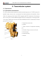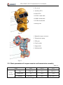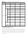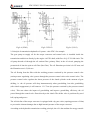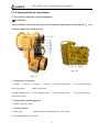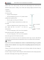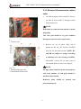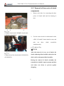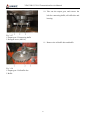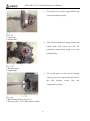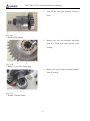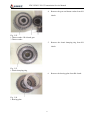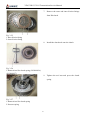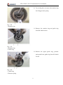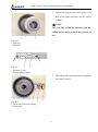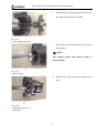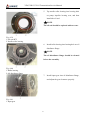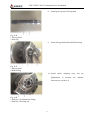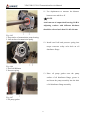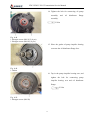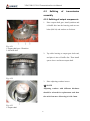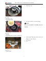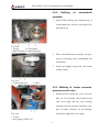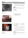
1
YD13/YD133/YL13 Transmission Service Manual
1
YD13/YD133/YL13 Transmission Service Manual
2
YD13/YD133/YL13 Transmission Service Manual
Foreword
This service manual covers the removal and refitting procedures, service technology and standard
requirements for YD13 transmission, so as to help service personnel understand the method of
removing and refitting it and to lay a solid technical foundation for them concerning the fault
determination and proper service. The manual is applicable to YD13/YD133/YL13 transmission as
they belong to the same serialized product.
This service manual mainly includes the following:
Chapter 1 Introduction
This chapter mainly describes precautions for servicing transmission, the meaning of all symbols
which are included in the following text and the tightening torque for plain bolts.
Chapter 2 Transmission system
This chapter mainly describes the gearshift principle of transmission, electric control system,
functional test and the operation and maintenance of transmission.
Chapter 3 Removal of transmission
This chapter describes how to remove each part properly and the relevant precautions in the
process.
Chapter 4 Refitting of transmission
This chapter describes how to refit each part properly and the relevant precautions in the process.
Chapter 5 Fault diagnosis and troubleshooting
This chapter introduces common fault diagnosis and troubleshooting for the EST controller and the
transmission.
Note
The specifications of parts covered by this Manual may be subject to modification due to the
improvement of this product, and no further notice will be given upon such modification, so
please contact SDLG for the latest data.
3
YD13/YD133/YL13 Transmission Service Manual
4
YD13/YD133/YL13 Transmission Service Manual
Contents
Foreword ....................................................................................................................... 3
Chapter 1 Introduction................................................................................................... 7
1.1 Safety precautions ............................................................................................. 7
1.2 Description of signs ......................................................................................... 10
1.3 Tightening torque table for plain bolts ............................................................ 10
2. Transmission system ............................................................................................... 12
2.1 Transmission.................................................................................................... 12
2.1.1 Description of transmission ..................................................................... 12
2.1.2 Basic parameters of torque converter and transmission assembly .......... 13
2.1.3 Gearshift principle of transmission.......................................................... 14
2.1.4 Transmission electrical control system .................................................... 17
2.1.5 Functional test of transmission ................................................................ 24
2.1.5 Functional test of transmission ................................................................ 25
2.1.6 YD13 Operation and maintenance of powershift transmission ............... 26
3 Removal of Transmission ......................................................................................... 32
3.1 Removal of transmission assembly ................................................................. 32
3.1.1 Removal of torque converter ................................................................... 32
3.1.2 Removal of transmission control valve ................................................... 33
3.1.3 Removal of oil filter................................................................................. 34
3.1.4 Removal of auxiliary PTO hub ................................................................ 34
3.1.5 Removal of input device .......................................................................... 35
3.1.6 Removal of transmission oil pipe and auxiliary PTO ............................. 36
3.1.7 Removal of three sets of clutch components ........................................... 38
3.1.8 Removal of parking brake and output device .......................................... 39
3.1.9 Removal of torque converter pressure regulating valve .......................... 43
3.2 Removal of transmission assembly ................................................................. 44
3.2.1 Removal of main PTO ............................................................................. 44
5
YD13/YD133/YL13 Transmission Service Manual
3.2.2 Removal of input assembly...................................................................... 45
3.2.3 Removal of three sets of clutch assemblies ............................................. 49
4 Refitting of Transmission ......................................................................................... 58
4.1 Refitting of transmission assembly ................................................................. 58
4.1.1 Refitting of three sets of clutches ............................................................ 58
4.1.2 Refitting of main PTO ............................................................................. 70
4.1.3 Refitting of input components ................................................................. 70
4.2 Refitting of transmission assembly ................................................................. 76
4.2.1 Refitting of output components ............................................................... 76
4.2.2 Refitting of countershaft assembly .......................................................... 79
4.2.3 Refitting of torque converter pressure control valve ............................... 79
4.2.4 Refitting of K3 and K4 clutch assemblies ............................................... 80
4.2.5 Refitting of KR&K2 and KV&K1 clutches............................................. 81
4.2.6 Refitting of auxiliary PTO ....................................................................... 82
4.2.7 Refitting of input assembly ...................................................................... 82
4.2.8 Refitting of main PTO assembly ............................................................. 84
4.2.9 Refitting of oil filter ................................................................................. 84
4.2.10 Refitting of transmission control valve.................................................. 84
4.2.11 Refitting of torque converter .................................................................. 86
5 Troubleshooting ........................................................................................................ 87
5.1 Removal and assembling tools for YD13 transmission: ................................. 87
5.2 Inspection tools for YD13 transmission .......................................................... 88
5.3 Fit clearance of critical parts of transmission ................................................. 88
6 Fault Diagnosis and Troubleshooting ....................................................................... 89
6.1 Fault diagnosis and troubleshooting for transmission EST controller ............ 89
6.2 Diagnosis and troubleshooting of common transmission faults ..................... 91
6
YD13/YD133/YL13 Transmission Service Manual
Chapter 1 Introduction
1.1 Safety precautions
Important safety notice
Service and maintenance is essential to the safe operation of vehicle. This Manual mainly
states how to remove and refit transmission assembly.
To prevent relevant from being hurt, this Manual takes
as a safety sign. With regard to
precautions attached with this sign, it is required to do operation carefully. In case of
potential hazard, first take into account the safety of yourself, and meanwhile take
necessary protective measures.
Safety notice
In the process of removal and refitting, improper operation methods will lead to part damage,
service life shortening and operating performance deterioration, and in addition, it may cause
personal injury. Therefore, please read related content in this Manual carefully before removing and
refitting any part.
1. The parameters, figures and content covered by this Manual apply to products of standard
configuration. As regard to variants, please consult SDLG or relevant data.
2. In the repair workshop, a separate or special area shall be provided for removal and refitting of
parts or for removed parts, corresponding tools and parts shall be placed at an appropriate area, and
the operation area shall be kept clean and free of oil dirt and other contaminant. Do not smoke at
any place other than the specified smoking area. Never smoke during operation, and it is required to
provide fire extinguishing device.
3. When welding operation is required, it shall be done by a trained and experienced welding
worker. During welding operation, it is required to use shield and wear appropriate protective
equipment such as welding gloves, blind, work cap and overall.
4. Before removing transmission & torque converter, be sure to clean dirt from the external surface
so as to prevent parts from being contaminated during removal.
5. During operation, do wear safety shoes and safety helmet. Do not wear inappropriate overall. The
overall must be buttoned. When striking parts with a copper rod, wear goggles.
7
YD13/YD133/YL13 Transmission Service Manual
6. Petrol, kerosene and water-based oil cleaner can be used to clean removed parts.
7. When using a crane or other hoisting equipment, first check the slings for damage. It is required
to use hoisting equipment with sufficient lifting capacity. During lifting operation, do lifting
operation slowly at appointed position so as to prevent parts from colliding with each other. Do not
work under lifted parts.
CAUTION
As the torque converter can not be positioned axially, avoid torque converter from sliding down
during removal and refitting of transmission. See Fig.1-1 as below.
Fig.1-1
8. When two or more persons are required to work simultaneously, they shall be in agreement with
the same operation procedure to avoid accident due to out of step.
9. Be sure to keep all tools properly and get familiar with their operating methods.
10. To align one hole with another, do not insert your hand or finger into the holes. As regards to
parts requiring assembly with hands, pay attention to the holding position and check it for risk of
crushing.
11. Be sure to perform inspection on the removed parts. The part of which the defect has already
affected the performance must be replaced.
12. After each part is fitted, no interference is allowed.
8
YD13/YD133/YL13 Transmission Service Manual
13. When passing the oil seal and the seal ring, through key groove, threaded hole and step during
installation, take corresponding protective measures so as to avoid damaging them.
14. In the process of assembling parts, the tools used shall match corresponding threaded fasteners
so as to prevent the fasteners from being damaged.
15. To tighten fittings body and plug screw, do not use a pneumatic wrench. Be sure to rotate them
to some extent by hand, and then use a torque wrench of corresponding specification to tighten
them to required torque.
16. When draining oil from the transmission, be sure to unscrew the drain plug slowly so as to
prevent oil from spurting out.
9
YD13/YD133/YL13 Transmission Service Manual
1.2 Description of signs
To make this Manual fully play its roles, the signs in Table 1-1 are used in respect of important
safety and quality requirements.
Table 1-1
Sign
Item
Remarks
During operation, pay special attention to safety.
Safety
During operation, pay special attention to safety because of
inside pressure.
During operation, pay special attention to technical
Note
requirements so as to ensure operation quality.
Weight of component or device and removal & refitting
modes.
Weight
Pay attention to the selection of sling and the posture during
operation.
Tightening
Pay special attention to tightening torque during assembly.
torque
Application
Points requiring the application of adhesive and grease.
Oil and water
Add a certain amount of oil, water and fuel.
Position for draining oil or water, as well as draining
Draining
amount.
1.3 Tightening torque table for plain bolts
Table 1-2
Nominal diameter of bolt, mm
Strength
Yield
class of
strength
bolt
N/mm2
8.8
640
9~12
22~30
10.9
900
13~16
30~36
6
8
10
12
14
45~59
78~104
124~165
65~78
110~130
180~210
Tightening torque, Nm
10
YD13/YD133/YL13 Transmission Service Manual
Nominal diameter of bolt, mm
Strength
Yield
class of
strength
bolt
N/mm2
8.8
640
193~257
264~354
10.9
900
280~330
380~450
Strength
Yield
class of
strength
bolt
N/mm2
8.8
640
952~1269
1293~1723
10.9
900
1400~1650 1700~2000
16
18
20
22
24
376~502
521~683
651~868
540~650
740~880
940~1120
Tightening torque, Nm
Nominal diameter of bolt, mm
27
30
33
36
39
1759~2345
2259~3012
2923~3898
2473~3298
2800~3350
4111~5481
Tightening torque, Nm
11
YD13/YD133/YL13 Transmission Service Manual
2. Transmission system
2.1 Transmission
2.1.1 Description of transmission
The YD13 type powershift transmission (with the maximum input power of 130 KW) consists of a
hydraulic torque converter and a rear-mounted fixed shaft transmission with multi-disc friction
clutch. Our company provides Loader LG938L equipped with YD13 transmission (4 forward gears
and 3 reverse gears), road roller RS8220 equipped with YD133 transmission (3 forward gears and 3
reverse gears, without torque converter) and road roller RP9300 with YL13 transmission (2 forward
gears and 2 reverse gears).
1. Transmission control valve
2. Oil filter
3. Torque converter oil temperature measuring
port
4. Oil outlet of torque converter to oil cooler
5. Oil suction pipe
6. Transmission body
7. Nameplate
Fig.2-1
12
YD13/YD133/YL13 Transmission Service Manual
8. Eye screw
9. Auxiliary PTO
10. Main PTO
11. KVK1 clutch shaft
12. KRK2 clutch shaft
13. K3K4 clutch shaft
14. Parking brake
Fig.2-2
1. Hydraulic torque converter
2. Transmission pump
3. PTO gear
4. Clutch (triad)
5. Output shaft
6. Parking brake
Fig.2-3
2.1.2 Basic parameters of torque converter and transmission assembly
Table 2-1
Items
YD13
YD133
YL13
Type
ZFW305
N/A
ZFW320
Torque ratio
2.3
N/A
2.52
Working
80~100°C, a
N/A
80~100°C, a
Torque
converter
13
YD13/YD133/YL13 Transmission Service Manual
temperature
maximum of 120°C
maximum of 120°C
Fixed-shaft
Fixed-shaft
Fixed-shaft
powershift
powershift
powershift
Transmission
4 forward gears and
3 forward gears
2 forward gears and
range
3 reverse gears
and 3 reverse gears
2 reverse gears
3.91
8.936
3.7
2.304
4.543
1.603
0.964
1.90
N/A
0.617
N/A
N/A
3.91
8.936
3.7
2.304
4.543
1.603
0.964
1.90
N/A
Built-in gear pump
Built-in gear pump
Built-in gear pump
13~17
13~17
14~17
Type
Forward I
Forward
II
Forward
III
Drive
Forward
ratio
IV
Transmission
Reverse I
Reverse
II
Reverse
III
Type of
transmission
pump
Pressure (bar)
2.1.3 Gearshift principle of transmission
1. Transmission structure principle
Actuator in YD13 transmission is composed of 6 clutches (i.e. K1, K2, K3, K4, KV (forward gear
clutch) and KR (reverse gear clutch)), and different gearshifts can be achieved through the
intercombinations among them, and each gearshift requires two clutches working simultaneously;
YD13, YD133 and YL13 transmission working principles are respectively shown in Fig.2-4,
Fig.2-5 and Fig.2-6.
14
YD13/YD133/YL13 Transmission Service Manual
Fig.2-4 (YD13)
Fig.2-5 YD133
Fig.2-6 (YL13)
2. Principle of transmission hydraulic oil system – take YD13 for example
The gear pump to supply oil for the torque converter and control valve is installed inside the
transmission and driven directly by the engine via PTO shaft, with flow of Q=35 L/1000 r/min. The
oil pump absorbs oil through the oil suction filter (primary filter) in the oil circuit, pumping the
pressurized oil into the spin-on oil filter (fine filter). The oil filteration precision is 0.025 mm, and
the filteration area is 5,100 cm2.
The oil flowing from the filter with the working pressure restricted by the pressure control valve
(main pressure regulating valve) passes through the pressure control valve to the control valve. The
pressure control valve regulates the boost pressure of the clutch cylinder at the moment of gear
shifting, i.e. the oil pressure will drop instantaneously when gearshifting, but after gearshifting
(after clutch engagement), it will return to 13~17 bar (the pressure restricted by the pressure control
valve). This can reduce the impact of gearshifting and improve gearshifting efficiency; the oil
passed through the control valve flows directly to the clutch. The shifter valve is positioned by steel
ball, spring and groove.
The oil inlet line of the torque converter is equipped with a by-pass valve (opening pressure of 8 bar)
to prevent the element damages due to high internal pressure of the torque converter.
According to the hydraulic transmission working principle, the oil is the medium for energy transfer
15
YD13/YD133/YL13 Transmission Service Manual
inside the torque converter. To avoid oil cavitation, the torque converter cavity should always be full
with oil, which is guaranteed by the torque converter pressure control valve (back pressure valve)
installed on the torque converter oil outlet line (opening pressure of 2.5 bar). The oil spilled from
the torque converter flows directly into the oil cooler.
The oil flowing from the oil cooler enters the transmission lubricating oil circuit, providing all
lubricating points with sufficient lubricating cooling oil. An additional pressure cut-off valve can be
installed to the transmission upon operational requirements.
The pressure cut-off valve can be easily controlled through a secondary brake pedal regulating the
air pressure or oil pressure. The hydraulically controlled pressure should be no less than 40 bar. The
pneumatically controlled pressure should be no less than 2.5 bar.The pressure cut-off valve
functions to cut off the oil pressure of the clutch oil line, and the clutch can be disengaged when the
gearshift valve stops working. So the engine output power can be supplied to the external pump
completely. If the pressure cut-off valve is used, there’s no need to put the gearshift valve at the
neutral position.
16
Fig.2-7 Schematic of transmission control hydraulic system
YD13/YD133/YL13 Transmission Service Manual
2.1.4 Transmission electrical control system
The gearshifting on the transmission is of electro-hydraulic control, and YD13 transmission with
EST semi-automatic gear controller is shown in Fig.2-8. Regulate the hydraulic slide valve through
the solenoid valves connected the selector to shift gears in turn without skipping. The gear pump to
supply oil for the torque converter and control valve is installed inside the transmission and driven
directly by the engine via PTO shaft. The hydraulic transmission oil passed through the oil suction
filter and the pressure control valve in the oil circuit flows into the transmission control valve, and
17
YD13/YD133/YL13 Transmission Service Manual
the transmission control pressure is 13~17 bar. The pressure control valve regulates the boost
pressure of the clutch cylinder at the moment of gearshifting, reducing the impact of gearshifting
and improving the gearshifting efficiency.
Fig.2-8
1. EST semi-automatic gear controller
(1) Principle
The EST series gear controller is an electric control system mainly composed of EST-4 (4-valve)
electric control unit as shown in Fig.2-8, with the semi-automatic control function for gearshifting.
This system mainly consists of the five components below:
(a) Gearshift lever DW-4 (four-gear selector), installed under the steering wheel and operated by
left hand;
(b) Electric control unit EST-4;
(c) Special purpose wire harness and connector;
(d) Solenoid valve on the control valve;
This control system is currently used to control the YD13 type transmission for the loader. Both the
signals of DW-4 selector and the other signals of the whole vehicle circuit are transferred to EST-4
electric control unit. After analysis and determination through combining all the signals and
according to the transmission control requirement, the electric control unit outputs the
corresponding voltage to the solenoid valve on the transmission control valve. The solenoid valve
assembly controls the corresponding oil circuit, and the hydraulic oil drives the appropriate clutch,
18
YD13/YD133/YL13 Transmission Service Manual
thus achieving the direction and gear control. The EST-4 electric control unit not only controls the
direction and the gearshifting on the transmission, but also provides four lines of output signals for
the whole vehicle circuit, including neutral gear signal AS (for interlock start), reverse gear signal
RF (for reverse indication), kickdown indication (H1) and alarm indication (H2). See “EST-4 output
signal function table” below for output signal status. These output signals are all positive outputs,
i.e. the voltage is +24 V when signal is available.
The EST-4 electric control unit has detection and protection functions, and all the outlet cable plugs
should be connected before powering it for operation. As for “Vehicle electrical system”, the power
positive and negative cables must be connected, the signal AS for interlock start should be also
applied, and others are connected as needed. If one of the solenoid valves on the transmission
control valve fails to be connected, or short circuit occurs or the power voltage appears abnormal,
the electric control unit will lock all outputs but only send out the alarm signal (signal lamp H2 will
flash, or the unit will click). In this case, switch off the power to clear the fault, and then switch on
the power again for normal operation.
For the operation of the control system, in addition to pulling the DW-4 selector lever to shift gears
and control directions, the brake signal BR and emergency braking BR2 in the vehicle electrical
system will also affect the output of the controller. Under forward I and II gears or reverse I and II
gears, if one of the two signals is connected to +24V, EST-4 output will remain the same as the
neutral of the corresponding gear on the DW-4.
Technical parameters:
Table 2-2
Rated voltage
DC 24 V
Working voltage range
DC 20~32 V
Input current
A maximum of 5 A
Output signal current
A maximum of 0.5 A for each line
Working temperature
-20~+70°C
Storage temperature
-40~+80°C
(2). Operation
19
YD13/YD133/YL13 Transmission Service Manual
Before starting the engine, put the DW-4 gear selector lever at “N” position, or the engine cannot be
started. After switching on the power, put the DW-4 selector at neutral when using it for the first
time, then shift to another gear as required, or the electric control unit EST-4 has no output;
(a) Push or pull the control lever of the gear selector horizontally to change the driving directions,
including F (Forward), N (Neutral) and R (Reverse); rotate the control lever to shift gears,
counterclockwise for upshift and clockwise for downshift, but never apply too much operating force.
Marks “1”, “2”, “3” and “4” on the lever refers to four gears among which “1” is the lowest speed
and “4” is the highest speed;
(b) As the controller has kickdown (KD) function, when DW-4 selector is put at “Forward” II gear,
pressing the lever forward can shift to I gear, and meanwhile the indicator lamp H1 comes on. This
function does not work at other gears other than II gear. Any method of the followings can cancel
the “kickdown”: (1) press the lever again; (2) rotate the lever to shift gear; (3) change directions; (4)
shift to neutral.
(c) When the vehicle runs at I or II gear, if the service brake or emergency brake is applied, the gear
signal from the electric control unit remains the same as the corresponding neutral, and the previous
gear will be recovered immediately after releasing the brake switch. But at III and IV gears, the
brake has no this function.
(d) When stopping the vehicle, the DW-4 gear selector should be put at “N”.
(e) In case the vehicle sends out an alarm when running (the vehicle stops running, the indicator
lamp H2 is flashing and the electric control unit is clicking), first pull the gear selector lever to
neutral (N), and if the alarm stops at this moment, continue the normal operation. If not, the line
may be faulty, and in this case, switch off the power, inspect carefully, clear the fault and lastly
switch on the power again to continue the operation.
Test methods for main components
(a) Measurement of solenoid valve: The resistance valve of the solenoid valve is about 60-70 Ohm,
and when measuring with a universal meter, switch off the power firstly and remove the round plug
connecting the control valve. The resistance value out of the range above indicates that the solenoid
valve is faulty and thus replacement is required.
20
YD13/YD133/YL13 Transmission Service Manual
(b) Test of speed sensor: In order to measure the resistance value of the speed sensor with a
universal meter, remove the power plug firstly, then measure between the two plug terminals, and
the resistance value within 1.02 K~1.2 K is normal. The resistance value of 0 or infinity indicates
that the sensor is damaged and thus replacement is required. Besides, inspect for its proper
installation position: the clearance between the sensor top surface and inspected gear peak should be
within 0.5~0.8 mm. Screw the sensor forward completely, then loosen half turn, and now the
clearance should be basically appropriate.
(c) Test of brake switch: The service brake and emergency brake pressure switches should apply
normally open contact, and the measured resistance should be infinite. With the brake switch
depressed, the resistance value should be 0.
(d) Test of DW-4 gear selector: A special purpose test box is required for testing DW selector: fit the
8-core socket of the test box with the DW-4 plug, and connect two power lines to DC 24 V power
(with the red line to +24 and the yellow line to ground). The eight indicator lamps on the test box
correspondingly display the eight position statuses of DW-4. Rotate the selector lever, and four
lamps for I to IV gears come on accordingly; pull the lever, and “Forward”, “Neutral” and
“Reverse” lamps come on accordingly; press the lever, and the “KD” lamp comes on accordingly.
The selector has no any fault if all the above are correct. And the selector is faulty and should be
replaced if one of the above is failed.
(e) Test of EST-4 electric control unit:
A special purpose test box is required for testing EST: Connect the 35-pin plug of the outlet cable
on the test box to the outlet line socket on the EST unit. Allow the hook at one end of the plug to
catch the pin on the unit end cap, align the plug and press hard till the other end of the plug is
clamped by the leaf spring. Connect a DW-4 selector on the 8-core square plug of the outlet cable.
Connect the two power lines of the test box to DC 24 V power (with the red line to +24 and the
yellow line to negative pole). Put the DW-4 at neutral II gear, and at the moment of powering, the
four indicator lamps of M1-M4 on the test box flash once simultaneously, and then only the
indicator lamp M2 remains on. Rotate or pull the selector lever, and the eight indicator lamps on the
test box should change in accordance with the function table below.
21
YD13/YD133/YL13 Transmission Service Manual
EST-4 Output signal function table
Table 2-3
Forward
Gear
Output
1
2
3
M1
M2
●
M3
●
●
M4
●
●
Reverse
Neutral
4
1
2
3
4
●
●
●
●
●
●
●
H1
02
03
04
●
●
●
●
●
●
●
●
●
AS
RF
01
●
●
●
●
●
●
●
●
It comes on under KD status.
It flashes when an alarm occurs. For the model with speed sensor, it comes on
H2
before connecting the speed sensor.
“●”: Indicates that there is signal output, and the lamp comes on.
22
Fig.2-9
YD13/YD133/YL13 Transmission Service Manual
23
Fig.2-10
YD13/YD133/YL13 Transmission Service Manual
24
YD13/YD133/YL13 Transmission Service Manual
2.1.5 Functional test of transmission
1. Test of electro-hydraulic control transmission
CAUTION:
The test shall be carried out only when the transmission temperature is within 80~95°C, and
when the engine runs at full throttle.
Fig.2-12
Fig.2-11
(1) Oil pressure test points:
3=Torque
converter 4=Torque
converter 8=Control oil pressure
inlet oil pressure
outlet oil pressure
10=KR clutch pressure
6=K1 clutch pressure
5=K2 clutch pressure
9=K4 clutch pressure
(2) Temperature measuring point:
4=Torque converter outlet
(3) Flow test points:
1=Filter inlet
2=Filter outlet (a minimum flow of 50 L/min);
Connecting threads for all points
25
11=KV clutch pressure
7=K3 clutch pressure
YD13/YD133/YL13 Transmission Service Manual
No.
Spec.
3, 5, 6, 7, 8, 9, 10, 11
M10×1;
1, 2
M26×1.5
Table 2-5
Control valve
Gear
Solenoid valve
M1
M2
M3
M4
●
●
●
V
1
Forward II
●
●
V
2
Forward III
●
V
3
4
3
Forward I
Fig.2-13
Clutch
Forward IV
●
Reverse I
●
Reverse II
Reverse III
●
●
●
R
1
●
●
●
R
2
●
●
R
3
2.1.6 YD13 Operation and maintenance of powershift transmission
1. Precautions for use
(1) Regularly change transmission oil and replace the filter in strict accordance with the
maintenance requirements.
(2) Before starting the engine, ensure that the control lever is at neutral position.
(3) Before each driving, release the parking brake (to relieve braking).
(4) In the case of combining or separating the engine with or from the transmission and the
transmission needs to be lifted, always avoid the torque converter from falling off.
(5) When stopping the vehicle, always keep the gear lever at neutral position.
(6) The working temperature, normally within 80-120°C, is permissible to rise to 120°C in short
time, especially note the control oil pressure of the transmission. When the transmission works
abnormally in service, stop the vehicle immediately for inspection.
(7) If a faulty vehicle needs to be repaired by electric welding, remove the cable plug from the
EST-computer controller (to cut off the circuit to the computer controller), which, otherwise, will be
burnt out due to impulse current during electric welding.
26
YD13/YD133/YL13 Transmission Service Manual
2. Operation
(1) Preparation and maintenance before driving
Prior to transmission operation, always add appropriate lubricating oil according to the specified
lubricating oil specification. For the transmission initial filling, the oil cooler, filter and connecting
lines must be full with the oil. So the initial filling amount is more than that of the later normal
maintenance. Since the installed torque converter oil flows through the oil cooler and pipe and
returns to the transmission in a stationary state, the correct oil level should be kept when stopping
the vehicle at the neutral gear, the engine running at idle speed and the transmission in a normally
thermal equilibrium temperature.
Check the oil level only when the control lever is put at neutral. Inset the oil dipstick to the oil tube
bottom when checking the oil level. When cleaning the filter of the main oil passage, be cautious
not to allow dirt and deposits into the oil circuit. Moreover, put a cover plate so as not to wet the
parking brake by the oil.
Note not to tighten the filter too tightly in the course of its installation.
(2) Driving and gearshifting
To start the engine, confirm the gear lever is at neutral position. For safety reasons, the parking
brake should be kept in the applied state before starting the engine, so as to prevent the vehicle
moving in the case of an engine start. After the engine is started, release the parking brake, select
the driving direction and gear, and then depress the accelerator slowly to move the vehicle. Until the
vehicle travels, the torque converter functions instead of a main clutch. Driving with a high gear is
possible under good road condition.
If the engine still runs and the transmission engages gear while the vehicle has been stopped, in
which case surely the engine is not shut down, the vehicle will creep on a straight road, for that
certain traction is generated through the torque converter during the engine idling. Therefore, it is
reasonable to keep the parking brake in the applied state when stopping the vehicle each time.
To stop the vehicle for a long time, the control lever must be put at neutral position. When the
vehicle is running, always remember to release the parking brake. Because as far as we know, it is
hard for the operator to realize this immediately, and due to large output torque ratio when the
27
YD13/YD133/YL13 Transmission Service Manual
torque converter changes speed, the vehicle itself can overcome the braking torque to run forcefully
even in the case of a rather normal operation. Consequently, the torque converter oil temperature
will rise and the brake will be overheated.
The torque converter influence may result in the engine speed increase when shifting from high
gear to low gear, especially the skipping gear. Therefore, if possible, depress the service brake first
to reduce the speed slowly, and then shift gear when shifting from high gear to low gear. First to
reduce the engine speed when the vehicle runs at high speed and driving direction is required.
(3) Temporary stop and stop
There is no rigid coupling between the engine and the torque converter output shaft, so when the
vehicle is to be stopped on a slope (either uphill or downhill) and the driver intends to leave, it is
recommended to apply the parking brake and put wedges under the wheels to prevent the vehicle
sliding.
(4) Towing
The maximum towing speed is 10 km/h, and the maximum towing distance is 10 km.
For a long distance, the broken-down vehicle should be loaded on another vehicle for transport.
(5) Oil temperature
The transmission oil temperature must be monitored by a temperature sensor. The maximum oil
temperature at the torque converter outlet should not exceed 120°C, and for the faultless control
assembly and the transmission with sufficient operating range, the temperature will not be higher. If
the oil temperature is higher than 120°C, stop the vehicle to check if there is oil leakage, and the
transmission should be at neutral and the engine run at a speed of 1200~1500 rpm, in which case
the oil temperature will drop soon to a normal valve (within approx. 2~3 min.). If the oil
temperature still keeps high, somewhere in the system is faulty, so clear the fault before the
operation.
The oil pressure during gear shifting is normally within 13~17 bar, and to monitor the control
pressure, a pressure gauge or pressure monitor must be installed. If some gear is engaged, and after
applying the clutch, the pressure drops to a value lower than the specified minimum pressure (the
pressure drops temporarily right at the moment the gear is shifted), eliminate the cause of the
28
YD13/YD133/YL13 Transmission Service Manual
pressure drop. A low control pressure will result in the clutch damage as the clutch lacks the
sufficient contact pressure, resulting in the friction plate keeping slipping and therefore being
overheated.
3. Maintenance
(2) Oil level check
—— Stop the vehicle at flat place.
—— Put the transmission gear lever at “N” position and the
parking brake at applied position.
—— Run the engine at an idle speed of 1000 rpm.
—— Loosen the oil dipstick counterclockwise, and take it out
for wiping.
—— Insert the oil dipstick into the oil pipe and screw it into
place tightly, then take it out after 3 s (at least two
measurements).
Fig.2-14
—— For the oil temperature of 40°C, the oil level should be
between the lower mark “Cold” and the center mark.
—— For the oil temperature of 80°C, the oil level should be
between the upper mark “Hot” and the center mark.
Oil level check in cold state can ensure the transmission and the torque converter with sufficient
circulating flow, but the final criteria to determine the oil level is to reach the oil level in hot state.
CAUTION:
If the oil level is below the minimum mark, add the recommended lubricating oil as specified,
until the oil level is within the correct range for the corresponding temperature (See Fig.2-16).
(2) Oil change
Change oil for the first time when the vehicle runs for 100 hours initially. After that, change oil
every 1,000 hours or at least once every year.
In order to change oil, stop the vehicle at flat place with the transmission at the working temperature,
take out the oil drain plug and seal ring to drain off the used oil.
29
YD13/YD133/YL13 Transmission Service Manual
——Start the engine and run it at idle speed.
—— Put the transmission control lever at “N” position.
—— Add oil to the upper mark of the “Zone Cold”.
—— Keep the parking brake at a safe position.
—— Select all gears one by one.
—— Check the oil level again, and add oil if necessary.
—— For the oil temperature of 40°C, the oil level should be between the lower mark “Cold” and
the center mark.
—— For the oil temperature of 80°C, the oil level should be between the upper mark “Hot” and the
center mark.
CAUTION:
The oil of the torque converter and cooler shall be drained off along with the used oil.
Oil change schedule: Table 2-6
Oil level
Part name
Initial change
Regular change
Standard
check
After running for
After running for 1,000 h
Delvac Super
100 h, and replace
but no longer than 1 year,
1300 CF-4/SAE
the oil filter.
and replace the oil filter.
(15W-40)
Transmission
Before
(YD13)
daily use
Other optional oil: Table 2-7
Acceptable oil specifications and standards (when HC-WG01 special oil is not available in your
region).
American Petroleum Institute (API) CF-4/CG-4/CH-4 (15W-40);
European Automobile Manufacturers Association (ACEA) E2-96 SAE (15W-40); ZF TE-ML03
SAE (15W-40);
Society of Automotive Engineers (SAE) 306 SAE (15W-40); Caterpillar T0-4 SAE (15W-40);
FUCHS TITAN SPECIAL HD CF-4/ SAE (15W-40);
(3) Filter replacement
Replace the oil filter while changing oil each time. The requirements are as follows:
30
YD13/YD133/YL13 Transmission Service Manual
—— Apply the seal ring with a thin layer of oil.
—— Push the oil filter inward till it contacts the sealing surface of the transmission, and then
tighten by 1/3~1/2 turn with hand.
—— Add oil and start the engine.
—— When the engine runs at an idle speed (about 1,000 rpm) and the transmission oil temperature
is just the working temperature, check the transmission oil level.
—— For the oil temperature of 40°C, the oil level should be within the “Zone Cold”.
—— For the oil temperature of 80°C, the oil level should be within the “Zone Hot”.
—— Check for tightening. Tighten with hand again when necessary.
31
YD13/YD133/YL13 Transmission Service Manual
3
Removal
Transmission
of
NOTE: The removal and Refitting of YD13
transmission is described here as an example,
which can be served as reference for YD133
and YL13 transmissions.
3.1
Removal
of
transmission
assembly
Fig. 3-1
1 Transition plate 2 Transition tube
3 Bolt
3.1.1 Removal of torque converter
1.
Remove
transition
plate
and
torque
converter from the transmission, drain off
the oil in the torque converter and put them
aside.
About 20 kg
2.
Remove the bolt 3 for connecting transition
tube and transmission.
3.
Remove the bolt for connecting casing and
the
transmission,
and
adjust
the
transmission to the appropriate position;
then use two bolts to push the casing out
and remove it.
Fig. 3-2
1 Hexagon screw 2 Tensioning pin
3 Connecting casing
32
YD13/YD133/YL13 Transmission Service Manual
3.1.2 Removal of transmission control
valve
1.
Use M8 hexagon socket wrench to remove
ten M8×45 and six M8×75 hexagon socket
bolts respectively.
NOTE
Bolts must be removed from outside to inside
diagonally.
The valve pad should be in good condition
during the removal of the control valve.
Fig. 3-3
1 Control valve
2.
Remove the six oil pipes (from top to
bottom are K2, K1, K3, K4, KV and KR)
from the oil duct plate in turn (NOTE: KV
and KR are subject to change according
to different rear axle steering of OEMs).
Meanwhile, remove the oil duct joint on
each clutch shaft to remove six oil pipes.
NOTE
Fig. 3-4
1 Oil duct plate pipe joint
2 Clutch shaft oil duct joint
Oil pipe joints should be protected properly,
and serial number of each pipe should be
marked with a marker.
Removed joints should be cleaned and
protected properly.
33
YD13/YD133/YL13 Transmission Service Manual
3.
Take off three M8×45 and six M8×35
hexagon socket bolts for connecting oil feed
plate and housing, then remove the oil feed
plate and partition, and put them aside.
NOTE
Bolts must be removed from outside to inside
diagonally.
Fig. 3-5
1 Oil duct plate
Removed oil duct plate should be cleaned and
protected properly.
3.1.3 Removal of oil filter
1.
Use the strap wrench to remove the oil filter,
and take off the O-ring.
Fig. 3-6
1 Strap wrench
3.1.4 Removal of auxiliary PTO hub
1.
Remove the bolt for connecting auxiliary
PTO hub and housing.
2.
Use crowbar to push out the hub, and take
off the PTO hub and seal ring. At this time,
the PTO hub has been removed completely.
Fig. 3-7
1 Hexagon socket screw
2 Auxiliary PTO hub
34
YD13/YD133/YL13 Transmission Service Manual
3.1.5 Removal of input device
1.
Remove the hexagon bolt for connecting
pump
impeller
bearing
seat
and
oil
distributor flange.
Fig. 3-8
1 Oil distributor flange
2 Pump impeller bearing seat
3 Hexagon screw
2.
Use two jackscrews to push out the input
device, and then use the copper bar to tap
and loosen the bearing seat. Afterwards,
take off the bearing seat and gasket.
Fig. 3-9
1 Pump impeller bearing seat 2 Gasket
3.
Remove the bolt for connecting main PTO
and housing, and use two M8×20 bolts to
push out the PTO assembly.
Fig. 3-10
1 Main PTO hub
2 Hexagon screw
35
YD13/YD133/YL13 Transmission Service Manual
4.
Support the transmission pump end cover
with a piece of φ30*400mm copper bar by
the left hand, and tap out the oil distributor
flange and transmission pump assembly
with another piece of copper bar by the right
hand, and put them aside.
NOTE
Appropriate position should be tapped by the
Fig. 3-11
1 Position to be supported by copper bar
copper bar, and the oil distributor flange and
transmission pump assembly should be
tapped in order to prevent against dropping.
3.1.6 Removal of transmission oil
pipe and auxiliary PTO
1.
Screw off the fixing bolts of transmission
oil pipe in turn, and then take out the pipe.
2.
Fig. 3-12
1 Transmission oil pipe
2 Transmission oil inlet cover
36
Remove the transmission oil inlet cover.
YD13/YD133/YL13 Transmission Service Manual
3.
Use circlip pliers to take off the snap ring
from the PTO shaft.
Fig. 3-13
1 Snap ring (45*1.75)
2 Circlip pliers
4.
Use copper bar to tap out the PTO shaft, and
then take off the PTO driving gear.
Fig. 3-14
1 Driving gear 2 PTO shaft
3 Retainer ring
5.
At this time, the PTO has been removed
completely.
Fig. 3-15
1 Ball bearing
37
YD13/YD133/YL13 Transmission Service Manual
3.1.7 Removal of three sets of clutch
components
1.
Remove the bolts for connecting the three
pieces of clutch shaft and the housing in
turn.
Fig. 3-16
1 K3&K4 clutch shaft 2 KR&K2 clutch shaft
3 KV&K1 clutch shaft
2.
Use the removal tool for clutch shaft to take
off K1, K2 and K3 clutch shafts in turn, and
take
out
three
clutch
assemblies
simultaneously.
About 15kg
NOTE
After the removal of every set of clutch, the
Fig. 3-17
1 Removal tool for clutch shaft (2938001828)
(2938001829)
clutch adjusting shim should be placed on the
shaft end for subsequent final assembly.
During the removal of clutch assembly, the
transmission should be put at proper position
and taken out slowly to prevent against
dropping.
38
YD13/YD133/YL13 Transmission Service Manual
3.1.8 Removal of parking brake and
output device
1.
Remove the two M10×30 lock plates from
the output shaft at the end of parking brake,
unscrew the bolts, and use two crowbars to
remove the parking brake together with the
parking brake flange assembly.
NOTE
Fig. 3-18
1 Parking brake
During the removal, force should be applied
slowly and protective measures should be
taken.
2.
Remove the oil seal from the output device.
3.
Take off the lock plate, and remove the bolt
Fig. 3-19
1 Oil seal
for connecting pressure plate and output
flange.
Fig. 3-20
1 Lock plate
2 Hexagon screw (M10*30)
39
YD13/YD133/YL13 Transmission Service Manual
4.
Remove the pressure plate, distance washer
and O-ring in turn.
Fig. 3-21
1 Pressure plate 2 Distance washer
3 O-ring
5.
Remove the output flange.
6.
Remove the oil seal.
Fig. 3-22
1 Output flange
NOTE
The oil seal should be removed with even
force in order to prevent against damage, or
by the use of special removal tool.
Fig. 3-23
1 Oil seal
40
YD13/YD133/YL13 Transmission Service Manual
7.
Use circlip pliers to remove the bearing
snap ring and compensation washer at the
front end of output shaft.
Fig. 3-24
1 Snap ring (120*4)
2 Compensation washer
8.
Use copper bar to tap the rear end of output
shaft.
Fig. 3-25
1 Rear end of output shaft
2 Copper bar
9.
Remove the output shaft, bearing and shaft
sleeve.
Fig. 3-26
1 Bearing 2 Output shaft
3 Shaft sleeve
41
YD13/YD133/YL13 Transmission Service Manual
10. Take out the output gear, and remove the
bolt for connecting baffle, oil baffle disc and
housing.
Fig. 3-27
1 Output gear 2 Connecting baffle
3 Hexagon screw (M8*16)
11. Remove the oil baffle disc and baffle.
Fig. 3-28
1 Output gear 2 Oil baffle disc
3 Baffle
42
YD13/YD133/YL13 Transmission Service Manual
3.1.9 Removal of torque converter
pressure regulating valve
1.
Remove the screw plug for fixing valve
housing assembly.
Fig. 3-29
1 Valve housing assembly 2 Screw plug
(CM30*1.5)
3 O-ring
2.
Remove valve housing assembly from the
torque converter pressure valve port on the
housing, namely the valve housing, valve
stem, pressure spring and washer.
Fig. 3-30
1 Pressure spring 2 Valve stem
3 Valve housing
43
YD13/YD133/YL13 Transmission Service Manual
3.2
Removal
of
transmission
assembly
3.2.1 Removal of main PTO
1.
Use circlip pliers to remove the retainer ring
for fixing driving gear on the PTO shaft.
2.
Remove the snap ring for fixing ball bearing
cone on the PTO shaft.
Fig. 3-31
1 Retainer ring
3.
Use screwdriver to expand the elastic
damping ring for fixing ball bearing, and tap
PTO shaft from the other side.
Fig. 3-33
1 Elastic damping ring
4.
Take off the driving gear, PTO shaft and ball
bearing.
Fig. 3-34
1 Driving gear
3 Ball bearing
2 PTO shaft
44
YD13/YD133/YL13 Transmission Service Manual
5.
Take off the two retainer rings for fixing
needle roller bearing on the PTO hub, and
remove the two retainer rings for fixing ball
bearing.
Fig. 3-35
1 Retainer ring
2 Needle roller bearing
3.2.2 Removal of input assembly
1.
Remove the four bolts for connecting
transmission pump and oil distributor
flange.
Fig. 3-36
1 Hexagon screw (M8*85)
2.
Remove the four bolts for connecting
transmission pump and oil distributor
flange.
Fig. 3-37
1 Hexagon screw (M8*115)
45
YD13/YD133/YL13 Transmission Service Manual
3.
Use copper bar to tap the output shaft to tap
out the transmission pump.
Fig. 3-38
1 Copper bar
2 Output shaft
4.
Take off the transmission pump, gasket and
output shaft, and remove the bolt for
connecting transmission pump cover and
pump housing.
Fig. 3-39
1 Hexagon screw
2 Output shaft
5.
Use circlip pliers to take off the bearing
snap ring from the output shaft, and remove
the
ball
bearing,
compensation washer.
Fig. 3-40
1 Ball bearing 2 Piston ring (30×2)
3 Snap ring (30×1.5) 4 Compensation washer
46
piston
ring
and
YD13/YD133/YL13 Transmission Service Manual
6.
Use copper bar to tap the output shaft, and
take off the transmission pump cover, inner
gear and other assemblies.
Fig. 3-41
1 Transmission pump housing
2 Transmission pump cover
7.
Remove the transmission pump inner gear,
output shaft, transmission pump cover and
ball bearing.
Fig. 3-42
1 Transmission pump inner gear
2 Transmission pump cover
8.
Take out the transmission pump outer ring
gear.
Fig. 3-43
1 Transmission pump housing
2 Outer ring gear
47
YD13/YD133/YL13 Transmission Service Manual
9.
Take off the safety valve at the torque
converter oil inlet on the oil distributor
flange: steel ball, pressure spring.
Fig. 3-44
1 Steel ball
2 Pressure spring
10. Use circlip pliers to take off the snap ring
for fixing the ball bearing on the driving
shaft.
Fig. 3-45
1 Snap ring
11. Use copper bar to tap and remove the
driving shaft.
Fig. 3-46
1 Driving shaft
2 Copper bar
48
YD13/YD133/YL13 Transmission Service Manual
12. Take off the driving gear, ball bearing and
roller bearing.
Fig. 3-47
1 Roller bearing 2 Driving gear
3 Ball bearing
13. Remove the plunger ring from the driving
shaft.
Fig. 3-48
1 Driving shaft
2 Plunger ring
3.2.3 Removal of three sets of clutch
assemblies
NOTE
The three sets of clutch assemblies are similar
in structure, and the removal process of K3
and K4 clutch assemblies is here described as
an example.
49
YD13/YD133/YL13 Transmission Service Manual
1.
Take off K4 cutch gear bearing, and put it
aside.
Fig. 3-49
1 Needle roller bearing
2.
Remove the face seal assembly and roller
from K3 clutch gear inner needle roller
bearing.
Fig. 3-50
1 Roller (12 pcs) 2 K3 clutch gear
3.
Remove the gear, washer and thrust washer
from K3 clutch.
Fig. 3-51
1 Washer 2 Thrust washer
50
YD13/YD133/YL13 Transmission Service Manual
4.
Remove the gear and thrust washer from K4
clutch.
Fig. 3-52
1 Thrust washer 2 K4 clutch gear
3 Thrust washer
5.
Remove the elastic damping ring from K4
clutch.
Fig. 3-53
1 Elastic damping ring
6.
Fig. 3-54
1 Bearing plate
51
Remove the bearing plate from K4 clutch.
YD13/YD133/YL13 Transmission Service Manual
7.
Remove the outer and inner friction linings
from K4 clutch.
Fig. 3-55
1 Inner friction lining
2 Outer friction lining
8.
Install the clutch tool onto the clutch.
9.
Tighten the tool nut and press the clutch
Fig. 3-56
1 Removal tool for clutch spring (2938001826)
(2938001827)
spring.
Fig. 3-57
1 Removal tool for clutch spring
2 Pressure spring
52
YD13/YD133/YL13 Transmission Service Manual
10. Use circlip pliers to remove the retainer ring
for fixing pressure spring.
Fig. 3-58
1 Retainer ring
11. Remove the retainer ring and guide ring
from K4 clutch in turn.
Fig. 3-59
1 Retainer ring
2 Guide ring
12. Remove the upper guide ring, pressure
spring and lower guide ring from K4 clutch
in turn.
Fig. 3-60
1 Guide ring
2 Pressure spring
53
YD13/YD133/YL13 Transmission Service Manual
13. Remove the piston and seal ring from K4
clutch. Then K4 clutch has been removed
completely.
Fig. 3-61
1 Seal ring 2 K3 clutch piston
3 Seal ring
14. Remove the elastic damping from K3 clutch
bearing plate.
Fig. 3-62
1 Elastic damping ring
15. Remove the bearing plate from K3 clutch.
Fig. 3-63
1 Bearing plate
54
YD13/YD133/YL13 Transmission Service Manual
16. Remove the outer and inner friction linings
from K3 clutch.
Fig. 3-64
1 Inner friction lining
2 Outer friction lining
17. Use the removal tool for clutch spring to
press the pressure spring of K3 clutch.
Fig. 3-65
1 Removal tool for clutch spring
(2938001826)
(2938001827)
2 Pressure spring
18. Use circlip pliers to remove the retainer ring
for fixing pressure spring.
Fig. 3-66
1 Retainer ring
55
YD13/YD133/YL13 Transmission Service Manual
19. Remove the retainer ring and guide ring
from K3 clutch in turn.
Fig. 3-67
1 Retainer ring
2 Guide ring
20. Remove the upper guide ring, pressure
spring and lower guide ring from K3 clutch
in turn.
Fig. 3-68
1 Guide ring
2 Pressure spring
21. Remove the piston and seal ring from K3
clutch.
Fig. 3-69
1 Seal ring 2 K4 clutch piston
3 Seal ring
56
YD13/YD133/YL13 Transmission Service Manual
22. Remove the needle roller bearing and
one-way valve from K3 & K4 clutches.
Then
K3
completely.
Fig. 3-70
1 One-way valve
2 Needle roller bearing
57
clutch
has
been
removed
YD13/YD133/YL13 Transmission Service Manual
4 Refitting of
Transmission
4.1
Refitting
of
transmission
assembly
4.1.1 Refitting of three sets of
clutches
NOTE
The three sets of clutch assemblies are similar
in structure, and the assembling process of
K3 and K4 clutch assemblies is here
described as an example.
1.
Tap needle roller bearing into clutch bearing
hole, and install retainer ring.
NOTE
Each component should be cleaned before the
assembling.
Fig. 4-1
1 Retainer ring
2 Needle roller bearing
58
YD13/YD133/YL13 Transmission Service Manual
2.
Install seal ring into the piston groove, and
then install piston assembly into the clutch
cylinder.
NOTE
The seal ring should be installed with the
sealing surface facing towards the pressure oil
face.
Fig. 4-2
1 Seal ring
2 Seal ring
Fig. 4-3
1 Pressure oil face
2 Friction lining surface
3.
Place the guide ring and pressure spring into
the clutch cylinder.
Fig. 4-4
1 Guide ring 2 Pressure spring
3 Guide ring
59
YD13/YD133/YL13 Transmission Service Manual
4.
Place the guide ring and retainer ring into
the clutch cylinder.
Fig. 4-5
1 Guide ring
2 Retainer ring
5.
Install the removal tool for spring onto the
clutch.
Fig. 4-6
1 Removal tool for clutch spring (2938001826)
(2938001827)
6.
Tighten the tool nut and press the clutch
spring.
Fig. 4-7
60
YD13/YD133/YL13 Transmission Service Manual
7.
Use circlip pliers to install the retainer ring
into the clutch cylinder snap spring groove,
and remove the removal tool for clutch
spring.
NOTE
In normal use, the outer friction lining of
clutch with the depth of grained groove worn
more than 2/3 should be replaced in time.
Fig. 4-8
1 Retainer ring
2 Circlip pliers
8.
Place the outer friction lining into K3 clutch
firstly.
NOTE
Outer friction lining should be placed into the
clutch firstly, and then outer and inner
friction
linings
placed
into
the
clutch
alternately.
Fig. 4-9
1 Outer friction lining
9.
Place the outer friction lining into K3
clutch.
Fig. 4-10
1 Inner friction lining
61
YD13/YD133/YL13 Transmission Service Manual
10. Place the bearing plate into K3 clutch.
Fig. 4-11
1 Bearing plate
11. Install the elastic damping ring into K3
clutch.
Fig. 4-12
1 Elastic damping ring
12. Use screwdriver to set the friction lining of
K3 clutch to the uppermost position, and
record the stroke of clutch piston measured
by the dial gauge. At this time, K3 clutch
has been assembled completely.
NOTE
The stroke should be measured several times
Fig. 4-13
1 Dial gauge
(more than 3 times) at different positions by
the use of dial gauge with the contact pressed
against the bearing plate. The reading of dial
gauge is the stroke of K3 clutch piston. Inner
62
YD13/YD133/YL13 Transmission Service Manual
friction
linings
with
different
thickness
(number of inner friction linings is fixed)
should be selected such that the piston stroke
(the same for three sets of clutches) is between
1.8-2.2 mm.
13. Tap the needle roller bearing of K4 clutch
into the clutch bearing hole, and install
retainer ring.
Fig. 4-14
1 Retainer ring
2 Needle roller bearing
14. Install seal rings into piston groove of K4
clutch.
NOTE
Seal ring should be installed with the sealing
surface facing towards the pressure oil face.
(See Fig. 4-3)
Fig. 4-15
1 Seal ring
2 Seal ring
63
YD13/YD133/YL13 Transmission Service Manual
15. Install K4 clutch piston into the clutch.
Fig. 4-16
1 Piston
16. Install guide ring and pressure spring into
the clutch cylinder.
Fig. 4-17
1 Guide ring 2 Pressure spring
3 Guide ring
17. Install guide ring and retainer ring.
Fig. 4-18
1 Guide ring
2 Retainer ring
64
YD13/YD133/YL13 Transmission Service Manual
18. Install the removal tool for clutch spring
onto the clutch, tighten the tool nut and
press the clutch spring.
Fig. 4-19
1 Removal tool for clutch spring (2938001826)
(2938001827)
19. Use circlip pliers to install retainer ring into
K4 clutch cylinder snap spring groove, and
remove the removal tool for clutch spring.
Fig. 4-20
1 Retainer ring
2 Circlip pliers
20. Place the outer friction lining into K4 clutch
firstly.
NOTE
In normal use, the outer friction lining of
clutch with the depth of grained groove worn
more than 2/3 should be replaced in time.
Fig. 4-21
1 Outer friction lining
65
YD13/YD133/YL13 Transmission Service Manual
21. Place the inner friction lining into K4
clutch.
Fig. 4-22
1 Inner friction lining
22. Place the bearing plate into K4 clutch.
Fig. 4-23
1 Bearing plate
23. Install the elastic damping ring into K4
clutch.
Fig. 4-24
1 Elastic damping ring
66
YD13/YD133/YL13 Transmission Service Manual
24. Use screwdriver to pick up the friction
lining of K4 clutch lightly, and record the
stroke of clutch piston measured by the dial
gauge.
NOTE
The stroke should be measured several times
(more than 3 times) at different positions by
Fig. 4-25
1 Dial gauge
the use of dial gauge with the contact pressed
against the bearing plate. The reading of dial
gauge is the stroke of K4 clutch piston. Inner
friction linings with different thickness should
be selected such that the piston stroke is
between 1.8-2.2 mm.
25. Install the thrust washer into K3 clutch gear.
NOTE
The thrust washer should be greased.
Fig. 4-26
1 K3 clutch gear
2 Thrust washer
26. Install the washer and thrust washer into K3
67
YD13/YD133/YL13 Transmission Service Manual
clutch.
Fig. 4-27
1 Thrust washer
2 Washer
27. Install K3 clutch gear.
NOTE
Splines of inner friction lining in the clutch
should be aligned before the gear installation.
Fig. 4-28
1 K3 clutch gear
28. Install the face seal assembly and roller to
K3 clutch gear inner needle roller bearing.
NOTE
The roller should be greased in order to
prevent against dropping during installation
of clutch assembly to the housing.
Fig. 4-29
1 Roller
68
YD13/YD133/YL13 Transmission Service Manual
29. Install the thrust washers into snap spring
and gear of K4 clutch cylinder.
NOTE
Thrust washers should be greased.
Fig. 4-30
1 Thrust washer
2 Thrust washer
30. Install needle roller bearing into K4 clutch
gear.
Fig. 4-31
1 Needle roller bearing
31. Install K4 clutch gear. At this time, K3 and
K4
clutches
have
been
assembled
completely.
NOTE
Splines of inner friction lining in the clutch
should be aligned before the gear installation.
Fig. 4-32
1 K4 clutch gear
69
YD13/YD133/YL13 Transmission Service Manual
4.1.2 Refitting of main PTO
1.
Install needle roller bearing into output
housing hub, and then install retainer ring.
Fig. 4-33
1 Retainer ring (2 pcs)
2 Needle roller bearing
2.
Install retainer ring into driving gear hole,
and install gear into output housing hub.
3.
Insert PTO shaft into gear hole, tap in the
ball bearing, and install 2 elastic damping
rings and 1 retainer ring.
Fig. 4-34
1 Driving gear
2 Retainer ring
4.1.3 Refitting of input components
1.
Fig. 4-35
1 Ball bearing
2 Auxiliary drive shaft
70
Tap ball bearing onto auxiliary drive shaft.
YD13/YD133/YL13 Transmission Service Manual
2.
Install flat key of gear pump inner gear onto
the shaft, and install the oil pump.
Fig. 4-36
1 Gear pump inner gear
3.
Tap another ball bearing into the oil pump
bearing hole.
NOTE
The auxiliary drive shaft must be able to
rotate flexibly.
Fig. 4-37
1 Ball bearing
4.
Install shaft snap spring and snap-in seal
ring.
Fig. 4-38
1 Snap spring (30×1.5)
2 Seal ring
71
YD13/YD133/YL13 Transmission Service Manual
5.
Tap needle roller bearing into bearing hole
on pump impeller bearing seat, and then
install the oil seal.
NOTE
The oil seal should be replaced with new one.
Fig. 4-39
1 Oil seal Φ75
2 Needle roller bearing
6.
Install roller bearing into bearing hole on oil
distributor flange.
NOTE
The oil distributor flange should be cleaned
before the assembly.
Fig. 4-40
1 Roller bearing
2 Oil distributor flange
7.
Install input gear into oil distributor flange,
and adjust the gear clearance properly.
Fig. 4-41
1 Input gear
72
YD13/YD133/YL13 Transmission Service Manual
8.
Install gear ring onto driving shaft.
9.
Insert driving shaft and install ball bearing.
Fig. 4-42
1 Driving shaft
2 Seal ring
Fig. 4-43
1 Driving shaft
2 Ball bearing
10. Install elastic damping ring, and use
depthometer
to
measure
between two end faces h.
Fig. 4-44
1 End face of oil distributor flange
2 End face of bearing cup
73
the
distance
YD13/YD133/YL13 Transmission Service Manual
11. Use depthometer to measure the distance
between two end faces H.
NOTE
Axial run-out of output shaft bearing: D=H-h
Adjusting washers with different thickness
should be selected such that D is 0.2-0.4 mm.
Fig. 4-45
1 Step surface of transmission pump bearing
2 Joint surface of transmission pump
12. Install steel ball and pressure spring into
torque converter safety valve hole on oil
distributor flange.
Fig. 4-46
1 Steel ball Φ20mm
2 Pressure spring
13. Place oil pump gasket onto the pump
surface of oil distributor flange, grease it,
and insert the pump assembly into the hole
of oil distributor flange assembly.
Fig. 4-47
1 Oil pump gasket
74
YD13/YD133/YL13 Transmission Service Manual
14. Tighten the bolt for connecting oil pump
assembly
and
oil
distributor
flange
assembly.
23 Nm
Fig. 4-48
1 Hexagon screw (M8*115) (4 pcs)
1 Hexagon screw (M8*85) (4 pcs)
15. Place the gasket of pump impeller bearing
seat onto the oil distributor flange face.
Fig. 4-49
1 Gasket
16. Tap in the pump impeller bearing seat, and
tighten the bolt for connecting pump
impeller bearing seat and oil distributor
flange.
23 Nm
Fig. 4-50
1 Hexagon screw (M8*28)
75
YD13/YD133/YL13 Transmission Service Manual
4.2
Refitting
of
transmission
assembly
4.2.1 Refitting of output components
1.
Place output shaft gear, install partition and
oil baffle disc into the housing, and use two
bolts (M8*16) and washers to fix them.
Fig. 4-51
1 Output shaft gear 2 Partition
3 Oil baffle disc
2.
Tap roller bearing to output gear shaft end,
and place it into oil baffle disc. Then install
spacer sleeve and insert output shaft.
Fig. 4-52
3.
Place adjusting washers in turn.
NOTE
Adjusting washers with different thickness
should be selected for replacement such that
the axial clearance of bearing is 0.1-0.3 mm.
Fig. 4-53
1 Output shaft
76
YD13/YD133/YL13 Transmission Service Manual
4.
Install snap ring.
5.
Use tool to install oil seal into housing.
Fig. 4-54
1 Adjusting washer
2 Snap ring (120*4)
NOTE
New oil seal should be installed after the
removal.
Fig. 4-55
1 Oil seal
2 Assembling tool for oil seal (2938001833)
6.
Install output flange and pressure plate, and
tighten two M10×30 bolts.
46 Nm
Fig. 4-56
1 Output flange
77
YD13/YD133/YL13 Transmission Service Manual
7.
Use special assembling tool to install lock
plate.
Fig. 4-57
1 Assembling tool for lock plate (2938001838)
8.
Install parking brake flange.
9.
Install brake drum wheel and pressure plate,
Fig. 4-58
1 Brake flange
tighten bolt and lock the lock plate.
Fig. 4-591
1 Parking brake
78
YD13/YD133/YL13 Transmission Service Manual
4.2.2
Refitting
of
countershaft
assembly
1.
Install roller bearing into bearing hole of
countershaft gear, and fix it with grease for
subsequent use.
Fig. 4-60
1 O-ring
2 Countershaft
3 Roller bearing 4 Countershaft gear
2.
Place countershaft gear assembly into gear
groove on housing, insert countershaft and
install shim.
3.
Install and tighten fixing bolt, and install
sealing washer.
Fig. 4-61
1 Countershaft gear
2 Shim
4.2.3 Refitting of torque converter
pressure control valve
1.
Install pressure spring and valve core into
hole on valve housing, then install O-ring
onto screw plug, and the valve housing
assembly into the pressure retaining valve
port of torque converter on the housing.
Afterwards, tighten the screw plug.
Fig. 4-62
1 O-ring
2 Screw plug (CM30*1.5)
79
YD13/YD133/YL13 Transmission Service Manual
4.2.4 Refitting of K3 and K4 clutch
assemblies
1.
Install O-rings and piston rings onto K3 and
K4 clutch shafts.
Fig. 4-63
1 Piston ring (3 pcs)
2 O-ring (49*3)
2.
Place clutch assembly into the housing, and
move the clutch to 3# shaft position; then
install nylon bar and thrust washer to clutch
assembly.
About 15 kg
NOTE
The clutch should be supported under the
Fig. 4-64
1 K3 and K4 clutch assemblies
2 Assembling tool for clutch (29380017611)
lower part by the tool to prevent against its
dropping.
3.
Tilt transmission to make it horizontal, and
install assembling tool for clutch.
Fig. 4-65
80
YD13/YD133/YL13 Transmission Service Manual
4.
Use depthometer to measure the height of
bearing step on clutch shaft h, and the
height of K3 clutch bearing roller from the
housing surface H.
NOTE
Axial clearance of clutch assembly A=H-h
Adjusting washer with appropriate thickness
should be assembled such that A is 0.1-0.3
Fig. 4-66
1 K3&K4 clutch shaft
2 K3 clutch bearing roller
mm.
5.
Take out the tool, install K4&K3 clutch
shaft, and tighten the nut for fixing clutch
assembly.
NOTE
K3&K4 clutch gear should be able to rotate
flexibly.
23Nm
Fig. 4-67
1 K3&K4 clutch assembly
2 Hexagon nut (M8) (2 pcs)
4.2.5 Refitting of KR&K2 and KV&K1
clutches
1.
Install
K2&KR
and
K1&KV
clutch
components into respective shaft holes on
the
housing,
and
adjust
the
bearing
clearance. Then insert K2 and K1 shafts,
and use three M8×18 bolts to fix them.
NOTE
Fig. 4-68
1 KV&K1 clutch assembly
2 KR&K2 clutch assembly
Adjusting washer with appropriate thickness
should be assembled such that A is 0.1-0.3
81
YD13/YD133/YL13 Transmission Service Manual
mm.
4.2.6 Refitting of auxiliary PTO
1.
Place transfer gear into the housing.
2.
Tap in PTO shaft to make the shaft retainer
ring fit the gear.
Fig. 4-69
1 PTO shaft
2 Retainer ring
3.
Use circlip pliers to install bearing snap ring
onto PTO shaft.
4.
Assembly PTO end cover, install gasket and
tighten the bolt for connecting PTO end
cover and housing.
NOTE
New gasket should be installed after the
removal.
Fig. 4-70
1 Snap ring (45*1.75)
16 Nm
4.2.7 Refitting of input assembly
1.
Place input device onto the housing, install
gasket, and use copper bar to tap it in.
NOTE
During the assembling, two bolts should be
screwed into the fixing screw holes, and new
gasket installed after the removal.
Fig. 4-71
1 Input assembly
82
YD13/YD133/YL13 Transmission Service Manual
2.
Assemble
transmission
oil
inlet
pipe
assembly and transmission oil pipe, and
tighten the hollow screw of transmission oil
pipe and housing.
34±5 Nm
Fig. 4-72
1 Transmission oil inlet cover
2 Transmission oil pipe
3.
Assemble connecting housing, and use
copper bar to tap it in.
NOTE
During the assembling, the locating pin holes
should
be
aligned,
and
tapping
force
distributed evenly on the connecting casing.
4.
Fig. 4-73
1 Tensioning pin
2 Hexagon screw
Tighten the bolts for connecting housing, oil
distributor flange and connecting casing.
NOTE
Pin holes should be aligned, and bolts
tightened several times diagonally.
68 Nm
83
YD13/YD133/YL13 Transmission Service Manual
4.2.8 Refitting of main PTO assembly
1.
Install PTO assembly, and tighten the bolts
and nuts for connecting PTO and housing.
NOTE
Bolts should be tightened several times
diagonally.
23 Nm
Fig. 4-74
1 Hexagon screw
4.2.9 Refitting of oil filter
1.
Screw up the oil filter.
Fig. 4-75
4.2.10
Refitting
of
transmission
control valve
1.
Place paper washer, lower partition, paper
washer and oil feed plate onto the valve
plate plane of housing respectively, and use
three M8×30 bolts and three M8×45 and six
M8×35 hexagon socket screws to fix them.
NOTE
Fig. 4-76
1 Oil feed plate
2 Paper washer
New paper washers should be installed after
the removal.
84
YD13/YD133/YL13 Transmission Service Manual
Before the assembling, the housing valve
plate, oil duct plate and partition should be
cleaned.
20 Nm
2.
Place paper washer, upper partition, paper
washer and control valve onto the oil feed
plate, and use ten M8×45 and six M8×75
hexagon socket screws to fix them.
NOTE
New paper washers should be installed after
the removal.
Bolts should be tightened several times
Fig. 4-77
1 Transmission control valve
diagonally.
20 Nm
3.
From top to bottom, the six oil holes on oil
feed plate are for K2, K1, K3, K4, KV and
KR (among them, KV and KR pipes are
subject to rear axle differential gear steering
of each OEM) pipes respectively; connect
them with various oil duct holes on K1, K2
and K3 shafts respectively.
Fig. 4-78
NOTE
Bolts should be tightened after the proper
adjustment of hose position.
55±5.5 Nm
85
YD13/YD133/YL13 Transmission Service Manual
4.2.11 Refitting of torque converter
1.
Install
intermediate
ring
and
torque
converter into connecting casing, and note
the positions of splined holes.
About 20kg
NOTE
As provision is not made for axial fixing, the
installed torque converter should be fixed
Fig. 4-79
1 Torque converter
2 Intermediate ring
properly to prevent against dropping.
86
YD13/YD133/YL13 Transmission Service Manual
5 Troubleshooting
5.1 Removal and assembling tools for YD13 transmission:
Code
2938001832
Name
Clutch nylon bar
1 Qty.
1
Purpose For assembling adjusting shims during the
Refitting of clutch assembly
Code
2938001833
Name
Output oil seal sleeve
2 Qty.
1
Purpose For assembling output shaft oil seal
Code
2938001838
Name
Special tool for lock plate
Qty.
1
3
Purpose Output flange pressure plate lock plate tool
for locking assembled output shaft lock
plate
Code
2938001835
Name
Special tool for bearing
Qty.
1
4
Purpose For assembling needle roller bearing 3526
Code
2938001836
Name
Special tool for bearing
Qty.
1
5
Purpose For assembling needle roller bearing 4026
87
YD13/YD133/YL13 Transmission Service Manual
Code
2938001829
2938001828
Name
Clutch shaft puller - Clutch shaft puller shaft
6.7
Qty.
sleeve
1
Purpose For removing clutch shaft
8
Code
2938001826
Name
Clutch pressing tool - shaft
Qty.
1
Purpose For removing and assembling clutch
piston return spring
9
Code
2938001827
Name
Clutch pressing tool – pressure plate
Qty.
1
Purpose For removing and assembling clutch
piston return spring
5.2 Inspection tools for YD13 transmission
Special tool
Tool name
Transmission pressure joint
Applicable position
Relief valve pressure joint
Remarks
6410006224
Used with pressure testing joint
Pressure tesing hose
4030000368
and pressure gauge
Pressure gauge with a range
6430000943
of 25 bar
5.3 Fit clearance of critical parts of transmission
S/N
Part
Fit clearance
1
Clutch piston stroke and clearance
1.8-2.2 mm
Axial clearance of three sets of
2
0.1-0.3 mm
clutch shaft assemblies
88
YD13/YD133/YL13 Transmission Service Manual
6 Fault Diagnosis and Troubleshooting
6.1 Fault diagnosis and troubleshooting for transmission EST controller
Table 5-1
Fault
S/N
Analysis
Fault diagnosis and troubleshooting
phenomenon
(1) Check power voltage, and in case
of power insufficiency, charge the
battery at the very first;
(2) Check if the starting circuit of the
engine involves poor connection or
damaged elements;
(1) Power voltage is not correct;
(3) Place the gear selector lever to the
(2) Starter relay or other related neutral position, when the starter relay
electric appliances is failed;
on the control unit should pull in;
Engine fails
1
(3) Gear selector lever DW-4 is (4) If no AS signal is received (i.e. the
to be started.
not placed in neutral position;
(4)
EST
control
unit
poor-contacted plug or failure.
voltage on the 0# circuit is not +24V),
incus the output signal of the control unit
may involve problems. In this case,
disconnect the plug of EST control
unit, and connect it again, always
clamped forcibly by hand to ensure
that both ends are clamped tightly and
properly connected. If it does work,
replace the EST control unit.
The vehicle (1)Open-circuit
2
or
short-circuit (1) Disconnect the plug, and measure
fails to run occurs;
the resistance of solenoid valves on the
regardless of (2) The solenoid valve is damaged. control valve is within 60Ω~70Ω. If
89
YD13/YD133/YL13 Transmission Service Manual
the
gear If it can be determined that the fault not, replace the faulty solenoid valve;
engaged
is thus resulted, the control unit will (2) Check the connecting cable for any
input a warning signal, i.e. indicator wear; and replace the faulty cable
H2 flashes and clicks can be heard when necessary;
from the control unit inside;
(3) Check if the incoming cable plug
(3) Gear selector lever DW-4 is of DW-4 and EST is dislodged; and
damaged or its plug is poorly clamp it when necessary;
connected;
(4)Replace DW-4 selector or EST
(4) EST-4 control unit is damaged or control unit;
its plug is poorly connected;
(5) Replace hydraulic control valves.
(5) Non-electrical faults such as oil
circuit fault or mechanical fault
occur.
(1) Check if the two switch can be
The vehicle
opened and closed flexibly, and if not,
(1) Brake switch BR or emergency
runs
as
do troubleshooting accordingly;
brake switch BR2 gets seized;
normal
3
1st/2nd
in
(2) Disconnect the cable between Br
(2) Short circuit occurs between
gear,
and BR2, if the gear is normal, check
signal wire BR and +24V wire;
but
not
in
the relevant wirings and repair the
(3) Solenoid valve M4 is damaged.
3th/4th gear.
faulty part;
(3) Replace the solenoid valve M4.
There is no
(1) This fault often occurs to the (1)
Check
the
speed
sensor
as
high-speed
engine equipped with output speed described above, and if it is damaged,
gear, and the
4
speed in 2nd
sensor when the sensor is not or replace;
poorly connected or damaged;
(2) Check the wire to sensor, and if it
gear is equal
(2)
to
that
3rd/4th gear.
Selector
DW-4
incurs is damaged, repair;
in
poorly-connected plug or damage.
90
(3) Replace selector DW-4.
YD13/YD133/YL13 Transmission Service Manual
No 1st/2nd/3rd (1) Any of internal elements of
(1) Replace the selector;
5
forward
selector DW-4 is damaged;
gears.
(2) Solenoid valve M3 is damaged.
(2) Replace solenoid valve M3.
No
reverse (1) Solenoid valve M1 is damaged;
(1) Replace the solenoid valve M1;
6
gear.
(2) Selector is damaged.
(2) Replace selector DW-4.
(1) Check the power supply system of
(1) The power voltage is not stable;
vehicle, and eliminate the factors
Gears
(2)
The
connector
is
poorly
related with voltage;
7
disappear
connected somewhere;
sometimes.
(3) The solenoid valve or electric
(2) Check, arrange and clamp all
connectors;
box works in an unstable state.
(3) Replace the electric box.
6.2 Diagnosis and troubleshooting of common transmission faults
Table 5-2
Fault
S/N
Analysis
Fault diagnosis and troubleshooting
phenomenon
1、 The
engine
circuit
2.
(like
starting 1.
power
Check the engine circuits with
reference to the Instructions to
supply, starter relay,
Engine Starting Circuit.
starter motor etc.) is 2.
Place the lever to the neutral
faulty.
position.
The lever is not placed 3.
Replace the fuse.
in the neutral position.
Arrange the connectors, and check if
Engine fails to be
1
4.
started.
3.
The fuse to the control
the
circuit on the engine is
energized.
burnt out;
4.
The
lever
5.
involves
poorly-connected plug
or faults.
91
handle
circuit
is
normally
Arrange the connectors or eliminate
the faults of electric box.
YD13/YD133/YL13 Transmission Service Manual
5.
The electric box incurs
poorly-connected plug
or faults.
1.
2.
3.
The oil pressure gauge 1.
Replace the oil pressure gauge;
is faulty.
Tighten the control valve bolt M8
2.
Bolt of transmission
with a torque of 20Nm;
control valve is not 3.
Replace the broken spring;
sufficiently tightened.
Replace the transmission pump;
Spring
Pressure at all gears
pressure
is low
broken.
of
4.
main 5.
valve
is
Replace the filter and clean the
control valve.
2
4.
Transmission
pump
wears out.
5.
Chips invade into the
transmission
control
valve or the valve gets
seized.
1.
After the engine stops, block the oil
passage to the corresponding KV
Oil
st
pressure
nd
clutch, and then start the engine and
rd
1 /2 /3
3
in
forward 1.
Forward gear clutch
gears is low but
incurs
normal
leakage.
engage 1st/2nd/3rd forward gears. If
internal
the pressure rises to a normal level, it
in
other
indicates that the clutch incurs
gears.
internal leakage and should be
repaired.
Oil
4
pressure
1st/2nd/3rd
in 1.
reverse
gears is low but
Reverse gear clutch 1.
After the engine stops, block the oil
incurs
passage to the corresponding KR
internal
leakage.
clutch, and then start the engine and
92
YD13/YD133/YL13 Transmission Service Manual
normal
in
engage 1st/2nd/3rd reverse gears. If the
other
gears.
pressure rises to a normal level, it
indicates that the clutch incurs
internal leakage and should be
repaired.
1.
passage to the corresponding K1
Oil pressure in 1st
5
After the engine stops, block the oil
forward and reverse 1.
Clutch
gears is low but
incurs
normal
leakage.
of
clutch, and then start the engine and
1st
gear
engage 1st forward/reverse gears. If
internal
the pressure rises to a normal level, it
in
other
indicates that the clutch incurs
gears.
internal leakage and should be
repaired.
1.
The
Replace O-ring.
plug is damaged.
Tighten the transmission control
2.
engagement
2.
6
O-ring on the throttle 1.
Bolts
of
pressure
valve bolt M8 with a torque of
time of all gears is
control valve are not
20Nm;
too short.
tightened
with
the
torque specified.
1.
The
Throttle
plug
is
engagement
1.
Clean and unblock.
2.
Clean and check.
blocked.
7
time of all gears is
2.
Pressure control valve
too long.
gets seized.
1.
Torque
8
incurs
converter
high
oil 2.
temperature.
3.
The oil temperature 1.
Replace.
sensor is faulty.
Replace.
2.
The oil temperature 3.
Check the oil level correctly and top
gauge is faulty.
up when necessary.
The oil level is low.
93
4.
Bleed off the radiator via the exhaust
YD13/YD133/YL13 Transmission Service Manual
4.
Air invades into the
outlet on the top (for engines with
radiator
exhaust outlet);
of
torque
converter.
5.
6.
7.
5.
Check if the oil circuits between the
Oil passage between
radiator to the transmission and the
the torque converter
radiator are blocked;
and the radiator is 6.
Check if the radiator can perform
blocked.
heat dissipation appropriately, and
The heat dissipating
check the tension of engine fan belt,
capacity of radiator is
and check the radiator outside for
low.
adhered dirt.
Back pressure valve of 7.
Check if the hose joint between the
the torque converter
transmission and the radiator is
gets seized.
inserted deeply into the transmission
so that the back pressure valve core
is pressed, the valve is seized and
thus the oil passage is blocked.
1.
The oil level is low.
2.
The
elastic
1.
plate
Check the oil level correctly and top
up when necessary.
connected between the 2.
Replace the elastic plate or the
engine and the torque
corresponding damaged part.
converter is torn off, 3.
Check if the power supply is
and
damaged, if the cable is worn out,
The vehicle fails to
9
the
power
run regardless of
connection
between
and
if
the
cable
connector
is
the gear engaged.
the torque converter
dislodged.
and the transmission 4.
Do troubleshooting as described
input gear is failed
above.
(seldom).
3.
5.
Power circuits of the
94
Check if resistance of solenoid valve
is 65+5Ω, and if it is 0 or ∝, it
YD13/YD133/YL13 Transmission Service Manual
4.
vehicle are faulty.
indicates that the solenoid valve is
Transmission involves
damaged and should be replaced.
low pressure.
5.
6.
7.
6.
Check
the
lever
as
per
the
The solenoid valve is
corresponding
troubleshooting
damaged.
method and replace when necessary.
The gear selector lever 7.
Check the electric box as per the
is damaged.
corresponding
The electric box is
method or with a PR68 detector.
troubleshooting
faulty.
1.
1.
Pressure
switch
If the 1st/2nd gear of the vehicle is
of
recovered after the emergency brake
emergency brake or
Vehicle fails to run
10
with
1st/2nd
pressure switch or the parking brake
parking
brake
is
gear
pressure switch is disconnected, it
damaged.
engaged.
indicates
2.
(M4)The
that
the
corresponding
solenoid
pressure switch is damaged.
valve M4 is in failure.
2.
Replace the solenoid valve.
The vehicle runs
1. Measure if the sensor resistance is
with a speed of 2nd
1020±100Ω, and if it is 0 or ∝, it
1. The speed sensor is
11
gear
when
3rd/4th
the
damaged.
gear
indicates that the speed sensor is
is
damaged and should be replaced.
engaged
1.
No
Eliminate the clutch internal leakage
gears involves internal
as described above.
leakage.
1st/2nd/3rd
12
The clutch of forward 1.
2.
2.
Arrange the lever wires or replace
The circuit in the gear
the lever.
selector lever incurs 3.
Measure if the resistance of the
burnt-out contract or
solenoid valve is 100±10Ω, and if it
poor connection.
is 0 or ∝, it indicates that the
forward gears.
95
YD13/YD133/YL13 Transmission Service Manual
3.
4.
The solenoid valve M3
solenoid valve is damaged and
is in failure.
should be replaced.
The
transmission 4.
Clean the transmission control valve.
control
valve
gets
seized.
1.
The clutch of reverse
1.
Eliminate the clutch internal leakage.
2.
Arrange the lever wires or replace
gear involves internal
leakage.
the lever.
2.
The circuit in the gear
3.
Measure if the resistance of the
selector lever incurs
13
No reverse gear.
solenoid valve is 65±5, and if it is 0
burnt-out contract or is
or ∝, it indicates that the solenoid
not energized.
valve is damaged and should be
3.
The solenoid valve M1
replaced.
is in failure.
4.
Clean the transmission control valve.
supply 1.
Check the power supply system of
4.
The valve gets seized.
1.
The
power
provided to ECU is
not stable.
2.
The
circuit
Gears
2.
power
to
the vehicle.
supply
ECU
is 3.
Do troubleshooting to the circuit of
engine.
Arrange the lever wires or replace
poorly connected.
the lever.
The gear selector lever 4.
Top up correctly.
works unstably or the 5.
Arrange connectors.
connector
Clean.
disappear
14
3.
sometimes.
is
poorly 6.
connector.
4.
The transmission oil
level is low.
5.
The solenoid valve or
96
YD13/YD133/YL13 Transmission Service Manual
the electric box works
unstably
or
their
connectors are poorly
connected.
6.
The valve gets seized.
1.
Bolts
securing
the
engine
with
transmission get loose.
2.
3.
The
15
transmission
produces
Check and tighten.
level is low.
Add oil to the normal level.
The
2.
propeller
shaft 3.
connecting
unusual
noises.
The transmission oil 1.
the 4.
transmission is faulty.
4.
5.
The
Replace the elastic plate.
Remove the propeller shaft, and
plate
check if there is still unusual noise
connected between the
produced; if were, check if the
engine and the torque
transmission
converter is torn off.
fault.
The
incurs
elastic
5.
Check the propeller shaft.
involves
mechanical
transmission
mechanical
fault inside.
The
vehicle
reverses
16
with 1.
1.
After the engine stops, block the oil
The clutch of reverse
passage to the KR clutch, and then
neutral
position
gear is ablated;
start the engine and engage the
engaged,
remains 2.
The valve gets seized.
reverse gear. If the vehicle runs as
still with 1st/2nd/3rd 3.
The solenoid valve M1
normal, it indicates that the reverse
forward
is in failure.
gear clutch is ablated and should be
The lever is faulty.
repaired mechanically.
gear
engaged, and runs 4.
as
normal
with
2.
97
Clean.
YD13/YD133/YL13 Transmission Service Manual
reverse
gear
engaged.
The
3.
Replace the solenoid valve.
4.
Replace the lever.
1.
After the engine stops, block the oil
vehicle
passage to the KV clutch, and then
proceeds
with
1.
neutral
engaged,
17
The clutch of forward
start the engine and engage the
gear is ablated.
1st/2nd/3rd forward gear. If the vehicle
2.
The valve gets seized.
runs as normal, it indicates that the
3.
The solenoid valve M3
forward gear clutch 1 is ablated and
is in failure.
should be repaired mechanically.
position
remains
still with reverse
gear engaged and
runs as normal with
1st/2nd/3rd
4.
The lever is faulty.
2.
Clean.
3.
Replace the solenoid valve.
4.
Replace the lever.
1.
After the engine stops, block the oil
forward
gear engaged.
passage to the K1 clutch, and then
start the engine and engage the 1st
The
vehicle
1.
K1 clutch is ablated.
2.
The valve gets seized.
3.
The solenoid valve is
can
forward/reverse gear. If the vehicle
only proceed with
18
1st forward/reverse
runs as normal, it indicates that the
clutch of the 1st gear is ablated and
in failure.。
gear engaged.
should be repaired mechanically.
4.
The lever is faulty.
98
2.
Clean.
3.
Replace the solenoid valve.
4.
Replace the lever.