1
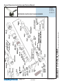
H ENRY T OOLS
Models
44-RAE
44-RAZE
44-RACE
Industrial Airtools at Work
General Safety and Maintenance
Manual
COLLET SPINDLE SHOWN
EXTENDED LENGTH RIGHT ANGLE GRINDER
Model
Number
44RAE
44RAZE
44RACE
Exhaust
Direction
Side
Throttle
Type
(L) Lever
or
(K) Safety
Lever
Speed
9000
to 11000
R.P.M
(11000rpm is
standard)
Power
Output
0.9 H.P.
(675 W)
Case
Material
Aluminum
Weight
Aluminum
2.75lbs.
1.2kg
Length
11.18
Inch
284mm
Diameter
1 3/4”
4.4cm
Air
Consumption
25 CFM
(11.8 L/S)
The Henry Tool Co., Manufactured by Henry Tools
Spindle
Thread
3/8-24 x 0.98
Inch
5/8-11 x 0.98
Inch
1/4 Inch BuiltIn Collet
498 So. Belvoir Blvd., South Euclid, OH 44121 U.S.A.
Ph: (216) 291-1011 or (800) 826-5257 ● Fax: (216) 291-5949 or (800) 303-2800
Email: [email protected] ● Website: www.Henrytools.com
General Operators Instructions and Service Manual
HENRY TOOLS, INC.
Ph: (216) 291-1011 or (800) 826-5257
EXTENDED LENGTH RIGHT ANGLE GRINDER
Models
44-RAE
44-RAZE
44-RACE
www.HenryTools.com | Page 50
For additional product information visit
our website.
Revised 04/24/10
General Operators Instructions and Service Manual
Part No
Description
Part No
Description
400-G-11
FRONT BEARING
500-G-44
3/8 I.D. FLANGE (4”-5” WHEELS)
400-G-17
Alum Side Exhaust Sleeve
500-G-47
1/2-13 JAM NUT
400-G-17-S
Steel Side Exhaust Sleeve
501-42A
1/2” I.D. FLANGE
400-G-4-GL
Aluminum Backhead
700-34
5/8-11 JAM NUT
400-G-4-GLS
Steel Backhead
700-37
THROTTLE LEVER PIN
400-G-25
MUFFLER
1100-680
5/8 I.D. FLANGE
400-G-26
THROTTLE LEVER
1100-682
400-G-34
SPRING
“(6”” OR SMALLER WHEELS)
3/8 I.D. FLANGE (5””-6”” WHEELS)”
400-G-38
COLLET NUT
591028
SCREW
400-G-42
3/8 I.D. FLANGE (2”-3” WHEELS)
591040
Star Washer for Bracket
400-G-47
3/8-24 JAM NUT
591048
SCREW
400-10
KEY
591106
SET SCREW (SPECIFY SPEED)
400-44
ROLL PIN
592016
SNAP RING
400-2G
CYLINDER WITH PIN INSTALLED
594016
O-RING
400-5
ROTOR
832636
GASKET
400-6
BLADE (5 are REQ.)
841552
3/8 NPT TO 3/8 NPT BUSHING
400-7
FRONT ENDPLATE
841553
3/8 NPT TO 1/4 NPT BUSHING
400-51
0-RING
844302
O-RING
402-126
SAFETY LEVER
869311
THROTTLE VALVE CAP
402-127
SAFETY LEVER PIN
834782
THROTTLE VALVE-INCLUDES 844302
402-128
LOCKOUT LEVER
402-129
SAFETY LEVER SPRING
404-1
Case
400-G-17
Exhaust (aluminum)
400-G-17-S
Exhaust (steel)
402-134
MUFFLER
404-1
ANGLE HEAD
404-2
BEARING CAP
404-3
UPPER OUTPUT SPINDLE BEARING
404-4
KEY
404-5
3/8-24 X .980 OUTPUT SPINDLE
404-5-CS
COLLET OUTPUT SPINDLE
404-5-625
5/8-11 X .980 OUTPUT SPINDLE
404-6
Wavy Washer (Note:2 are req’d)
404-7
LOWER OUTPUT SPINDLE BEARING
404-8
SNAP RING
404-9
510120
REPAIR KIT with Gear Set
510121
REPAIR KIT WITHOUT GEARS
402-26
Safety Lever Assembly
ACCESSORIES
DESCRIPTION
CP-53
WASHER
300-16
1/8” COLLET ADAPTER
300-16-3/32
1/4” TO 3/32” COLLET ADAPTER
400-78
3/8-24 TO 5/8-11 ADAPTER
405-24
BACKING PLATE FOR 490-KR
490-K
“3/8-24 X TYPE 27 ADAPTER ASSY.
.980”
490-KR
“3/8-24 X TYPE 27 ADAPTER ASSY.
.580”
REAR MOTOR BEARING
490-1
BACKING PLATE FOR 490-K
404-10
GEAR SET (sold only as set)
490-2
NUT FOR 490-K & 490-KR
404-12
SPACER RING
1100-660
3/8-24 TO 5/8 I.D. TYPE 27 ADAPTER ASSY.
404-14
SPINDLE
1100-661
3/8-24 TO 5/8 I.D. BACKING PLATE
404-19
REAR ENDPLATE
1100-662
3/8-24 TO 5/8 I.D. ADAPTER NUT
404-20
MOTOR SPACER
1100-664
3/8-24 TO 7/8 I.D. BACKING PLATE
404-38
BEARING COVER
1100-666
3/8-24 TO 7/8 I.D. ADAPTER NUT
404-39
SNAP RING
1100-668
3/8-24 TO 7/8 I.D. TYPE 27 ADAPTER ASSY.
404-40
DEAD HANDLE
1100-680
5/8” Adaptor for Type 1 wheels
404-41
MOTOR CASE
1100-692
5/8-11 TO 7/8 I.D. TYPE 27 ADAPTER ASSY.
404-44
OFFSET HANDLE BRACKET
1100-694
5/8-11 TO 7/8 I.D. BACKING PLATE
404-46
CASE EXTENSION
1100-696
5/8-11 TO 7/8 I.D. ADAPTER NUT
For additional product information visit our website.
HENRY TOOLS, INC.
ASSEMBLIES
PART
Revised 04/24/10
Ph: (216) 291-1011 or (800) 826-5257
EXTENDED LENGTH RIGHT ANGLE GRINDER
Models
44-RAE
44-RAZE
44-RACE
www.HenryTools.com | Page 51
General Operators Instructions and Service Manual
Part No
849259
849259-A
889271
889271-A
849848
849848-A
GUARDS
4503
Description
5/8-11 SANDING PAD NUT
3/8-24 SANDING PAD NUT
5/8-11 4” SANDING PAD (MAX
12000 RPM)
3/8-24 4” SANDING PAD (MAX
12000 RPM)
5/8-11 5” SANDING PAD (MAX
10000 RPM)
3/8-24 5” SANDING PAD (MAX
10000 RPM)
3” TYPE 27 GUARD
www.HenryTools.com | Page 52
Part No
4504
4505
4506
TOOLS/
WRENCHES
490-3
102-SPWR
1100-044
1100-056
1100-063
1100-075
1100-094
Description
4” TYPE 27 GUARD
5” TYPE 27 GUARD
6” TYPE 27 GUARD
PIN SPANNER
WRENCH FOR SANDING PAD NUT
7/16” WRENCH
9/16” WRENCH
5/8” WRENCH
3/4” WRENCH
15/16” WRENCH
For additional product information visit
our website.
Revised 04/24/10
HENRY TOOLS, INC.
Ph: (216) 291-1011 or (800) 826-5257
Models
44-RAE
44-RAZE
44-RACE
General Operators Instructions and Service Manual
HENRY TOOLS, INC.
Ph: (216) 291-1011 or (800) 826-5257
EXTENDED LENGTH RIGHT ANGLE GRINDER
Models
44-RAE
44-RAZE
44-RACE
Revised 04/24/10
For additional product information visit our website.
www.HenryTools.com | Page 53
General Operators Instructions and Service Manual
EXTENDED LENGTH RIGHT ANGLE GRINDER
. DISASSEMBLY
1. PLEASE NOTE: The brass spacers that were installed
by the factory are necessary for this tool to operate efficiently. When disassembling this tool examine how spacers are arranged. They must be installed exactly the same
way. Failure to do this will cause improper gear spacing,
which causes pre-mature tool failure.
2. Disconnect air & remove all wheels and accessories.
3. Secure anglehead in vise on dead handle boss. Never
Squeeze anglehead in vise. This will distort bearings and
ruin gear alignment. Remove Backhead(400-G-4). Unscrew
case (400-G-1) 3. Remove deflector (400-G-17-S).
4. Pull motor from right angle head. Be careful to note
location of shims.
5. Remove snap ring (404-39),wafer(404-38),Oring(594016), and snap ring (592016).(Some of these may
not be present).
6. Install brass or aluminum jaws in vise. Grasp the O.D.
www.HenryTools.com | Page 54
ASSEMBLY
1. Support front bearing(400-G-11) on drill block. Press spindle(404-14) through bearing until it bottoms on shoulder.
2. Slide front thrust(400-7)over the spindle and onto front bearing. Place key(400-10)
into keyway in spindle. Slide rotor down over shaft.
3. Grasp rotor in vise snugly and replace pinion gear(404-10) and wrench firmly.
4. Support bearing and pinion gear in downward position. Place five blades(400-6) in
slots. Slip cylinder(400-2-G) over rotor.
5. Install rear thrust(404-19) locating cylinder pin in small hole of rear thrust plate
(404-19).
6. Place bearing (404-9) in rear thrust and tap into place with suitable bearing driver.
Place snap ring(592016) in spindle groove. Place O-Ring (594016) and (404-38) and snap
ring 404-39 in endplate groove.
7. Support bearing(404-7) on inner race. Press spindle (404-5) through bearing until it
bottoms on shoulder.
8. Install key (404-4) and line up with keyway of ring gear(404-10).
9. Support gear on inner diameter and press spindle through. Slide spacer(404-12) on
spindle. Replace snap ring (404-8) on spindle groove.
10. Support threaded end of spindle and press on bearing(404-3). Tighten screw
(591028) into end of spindle. Press spindle assembly into cap(404-2) Grease gear.
11. Install two spring washers(404-6) into angle head (404-1)(CURVED SIDE DOWN).
12. 1nstall spindle assembly into angle head housing, secure in vise and tighten cap
(404-2).
13. Re-Locate angle head in vise-so that the motor can be installed vertically.
14. Replace shim(404-20),
15. Grease the gear. Place motor assembly into angle head while turning spindle(404-5)so that gears mesh. Tap lightly on rear of motor to insure that is fully seated.
16. Install exhaust deflector (400-G-17-S). Place O-ring(400-51) on motor case(400-G-1)
and screw onto angle head.
17. The deflector (400-G-17) should be snug, but can be turned. Place a few drops of oil
into motor inlet.
18. Screw on (404-46) and backhead (400-G-4-GL) Replace guard on tool.
19. CHECK RPM WITH TACHOMETER.TOOL MUST RUN AT OR BELOW SPEED STAMPED ON
TOOL.
INSTALLATION
For most efficient operation, 90 psig (620 kPa) of clean dry air is required at the tool with
the tool running, with-out extreme fluctuation. Minimum recommended hose size is 3/8”
I.D. when the length of the hose is eight feet or less. An air line filter and lubricator, should
be used. Hose should be blown out before attaching to the tool.
Loss of Power
A loss of power may not be related to the tool. First, check the air line pressure. It should be
90 psi at the tool while operating.
LUBRICATION
Lubricate the motor with an air line lubricator, using a light air motor oil. Adjust the lubricator to dispense one drop per cycle or three drops per minute.
CAUTION Do not use substitutes for oil and grease. This could result in damage to the tool.
For additional product information visit
our website.
Revised 04/24/10
Ph: (216) 291-1011 or (800) 826-5257
of cylinder(400-2-G)and end plate(404-19). Using a 3/16” punch, tap spindle out rear bearing (404-9).
7. Remove cylinder, blades(400-6). 8. With rotor (400-5) still on spindle (404-14), grasp
the rotor in vise snugly and remove pinion gear(404-10).
8. Remove rotor(400-5) Remove key and front thrust plate(400-7).
9. Press bearing (400-G-11) off of spindle.
10. Secure angle head in vise and unscrew cap (404-2).
11. Remove from vise and tap on spindle with a plastic hammer. The spindle assembly and
spring washers (404-6) will slide out.
12. Clamp flats of spindle(404-5) in vise. Using a plastic hammer, tap evenly on O.D. of
bearing cap until free of bearing (404-3). Note position of shims. Using a 9/64” T-Handle
hex wrench unscrew (591028) screw.
13. Press bearing (404-3) off spindle.
14. Remove snap ring (404-8) .Support bearing (404-7) and press spindle through with
1/4” punch. This will remove spacer (404-12), gear (404-10) and bearing(404-7).
15. Remove key (404-4).
HENRY TOOLS, INC.
This tool is designed to operate on 90 psig (6.2 bar)
maximum air pressure with 1/4” (8 mm) hose. Do not use
a grinder without recommended wheel guard. Do not use
any wheel for which the operating speed listed is lower
than the actual free speed of the Grinder.
SAFETY
1. Before operation check spindle speed with a tachometer. If the RPM exceeds the rated speed stamped on tool,
servicing is required.
2. Inspect grinding wheels for bends, chips, nicks, cracks
or severe wear. If the wheel has any of these, or has been
soaked in liquids do not use. On brushes check for loose
wires that may fly off in operation.
3. Start new grinding wheels under a steel bench. Run at
full throttle for one minute. Defective wheels usually come
apart immediately. When starting a cold wheel apply to
work slowly, allow wheel to warm gradually.
4. Model 44RAE grinders equipped with collet spindles
are intended for mounted wheels,points and carbide
burrs. They are not guarded for type 1 wheels. If you
have a type 1 wheel application,please purchase a
guard (4504,4505,etc.) 5.The Model 44RAE Grinders are
equipped with a guard from the manufacturer. A guard is
not needed for :
. a.) mounted wheels two inches (50 mm) or smaller;
. b.) grinders used for internal work, while within the
work being ground.
5. At least one-half of the mandrel length (i.e. mounted
wheel, burr, etc.) must be inserted into the collet. Secure
collet chuck tightly.
6. Safety levers are available from the manufacturer.
(402-26).
7. Before mounting or removing a wheel, disconnect
grinder from air supply. The wheel should fit properly on
arbor, do not use bushings or wheel flanges to adapt a
wheel to any arbor unless recommended by the manufacturer. (Wheel flanges should be at least 1/3 the diameter of
the grinding wheel.)
8. Wear safety goggles and other protective clothing.
Continuous exposure to vibration may cause injury to
your hands and arms.(See regulations.)
9. Properly maintained air tools are less likely to fail or
cause accidents. If tool produces an unusual sound or
vibrations repair immediately.
Models
44-RAE
44-RAZE
44-RACE