1
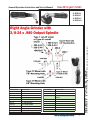
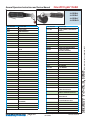
new 2010 year MODEL
H ENRY T OOLS
Industrial Airtools at Work
General Safety and Maintenance
Manual
Models
46 BBRA4
46 BBRA2
46 BBRAC
46 BBRAD
Features: Small Round Head
for grinding in confined
spaces.
Model
Number
46 BBRA4
46 BBRA2
46 BBRAC
46 BBRAD
Case
Material
Exhaust
Throttle
Direction
Type
Front
(L) Lever
or
or
Side
(K) Safety
Lever
Weight
Aluminum Steel
Steel
2.8
or
Lbs
Aluminum (1.3
Kg)
3.5 Lbs
(1.6 Kg)
Speed
13000
to 14000
R.P.M
(13500rpm
is standard)
Power
Output
0.9 H.P.
(675 W)
Length Diameter
9.1
Inches
(231
mm)
Air
Consumption
1.6
25 CFM
Inches
(11.8 L/S)
(41 mm)
Case
Material
Steel
or
Aluminum
Spindle Thread
3/8-24 x 0.98 Inch
(25mm)
5/8-11 x 0.98 Inch
(25mm)
1/4 Inch Burrs/Mounted Points
Burrs/M.P. of Size
Matching the Insert
Size
The Henry Tool Co., Manufactured by Henry Tools
498 So. Belvoir Blvd., South Euclid, OH 44121 U.S.A.
Ph: (216) 291-1011 or (800) 826-5257 ● Fax: (216) 291-5949 or (800) 303-2800
Email: [email protected] ● Website: www.Henrytools.com
General Operators Instructions and Service Manual
new 2010 year MODEL
HENRY TOOLS, INC.
Ph: (216) 291-1011 or (800) 826-5257
Models
46 BBRA4
46 BBRA2
46 BBRAC
46 BBRAD
www.HenryTools.com | Page 80
For additional product information visit
our website.
Revised 05/05/10
General Operators Instructions and Service Manual
new 2010 year MODEL
PART NUMBER
DESCRIPTION
PART NUMBER
DESCRIPTION
209-1
ERICKSON STYLE COLLET NUT
400-G-25
MUFFLER SCREEN
209-1/8
1/8” COLLET INSERT
400-G-26
THROTTLE LEVER
209-1/4
1/4” COLLET INSERT
400-G-29
209-5/16
5/16” COLLET INSERT
THROTTLE VALVE-INCLUDES
844302
209-3/8
3/8” COLLET INSERT
400-G-34
SPRING
209-1/4
1/4” COLLET INSERT
400-G-38
COLLET NUT
209-5/16
5/16” COLLET INSERT
400-G-42
3/8-24 FLANGE (2”-3” WHEELS)
209-3/8
3/8” COLLET INSERT
400-G-47
3/8-24 JAM NUT
300-G-29
BEARING
400-2G
CYLINDER
400-G-11
FRONT BEARING
400-5
ROTOR
Revised 05/05/10
For additional product information visit our website.
HENRY TOOLS, INC.
Ph: (216) 291-1011 or (800) 826-5257
Models
46 BBRA4
46 BBRA2
46 BBRAC
46 BBRAD
www.HenryTools.com | Page 81
General Operators Instructions and Service Manual
new 2010 year MODEL
DESCRIPTION
PART NUMBER
DESCRIPTION
400-6
BLADE (5 REQ.)
1100-680
400-7
FRONT ENDPLATE
5/8 I.D. FLANGE (6” OR SMALLER
WHEELS)
400-9
REAR OUTPUT BEARING
1100-682
3/8 I.D. FLANGE FOR 5”-6” WHEELS
400-10
KEY
590031
BEARING
400-44
CYLINDER ROLL PIN
591046
SCREW
400-46
SNAP RING
400-51
O-RING
592016
SNAP RING
402-126
SAFETY LEVER BARE
594016
O-RING
402-127
SAFETY LEVER PIN
832636
GASKET
402-128
LOCKOUT LEVER FOR SAFETY
LEVER
841552
3/8 NPT TO 3/8 NPT BUSHING
841553
402-129
SAFETY LEVER SPRING
3/8 NPT TO 1/4 NPT
BUSHING(STANDARD)
402-132
ALUMINUM CASE (SPECIFY SPEED)
402-132-S
STEEL CASE (SPECIFY SPEED)
844302
O-RING
869311
THROTTLE VALVE CAP
GUARDS
402-132-S-FT
STEEL FLOW THRU CASE
404-9
REAR MOTOR BEARING
404-19
REAR ENDPLATE
404-38
BEARING COVER
404-39
SNAP RING
490-3
PIN SPANNER
406-1B
OUTPUT HOUSING (MAIN HEAD
UNIT)
1100-044
7/16” WRENCH
1100-063
5/8” WRENCH
406-4
KEY
1100-068
WRENCH 11/16”
406-10
GEAR SET (SOLD AS SET)
1100-075
WRENCH 3/4”
406-14A
MOTOR SPINDLE
1100-094
15/16” WRENCH
406-15
GEAR SPACER
ASSEMBLIES
406-15-CS
COLLET OUTPUT SPINDLE
PART NUMBER
DESCRIPTION
406-17
3/8-24 X .980 OUTPUT SPINDLE
510240
MOTOR REPAIR KIT
406-17-625
5/8-11 X .980 OUTPUT SPINDLE
510118
ANGLE HEAD REPAIR KIT
406-17-DA
ERICKSON COLLET SPINDLE
402-26
SAFETY LEVER ASSY.
406-38
LOCKNUT
AA-402-132
406-39
MOTOR RETAINER
ALUMINUM CASE ASSY. SPECIFY
SPEED FOR CASE ASSY.
406-40
HEAD RETAINER NUT
AA-402-132-K
406-41
COUPLING
ALUMINUM SAFETY CASE ASSY.
SPECIFY SPEED FOR CASE ASSY.
406-45
SNAP RING
AA-402-132-S
410-G-17F-S
STEEL FRONT EXHAUST SLEEVE
STEEL CASE ASSY. SPECIFY SPEED
FOR CASE ASSY.
410-G-17-S
STEEL SIDE EXHAUST SLEEVE
(STANDARD)
AA-402-132-SK
STEEL SAFETY CASE ASSY. SPECIFY SPEED FOR CASE ASSY.
500-G-44
3/8 ID FLANGE (4”-5” WHEELS)
700-34
5/8-11 JAM NUT
700-37
THROTTLE LEVER PIN
www.HenryTools.com | Page 82
4604-27
4” TYPE 27 GUARD
4605-27
5” TYPE 27 GUARD
TOOLS /WRENCHES
ACCESSORIES
PART NUMBER
DESCRIPTION
300-16
1/8” COLLET ADAPTER
400-78
3/8-24 TO 5/8-11 ADAPTER
405-24
BACKING PLATE FOR 490-KR
For additional product information visit
our website.
Revised 05/05/10
HENRY TOOLS, INC.
PART NUMBER
Ph: (216) 291-1011 or (800) 826-5257
Models
46 BBRA4
46 BBRA2
46 BBRAC
46 BBRAD
new 2010 year MODEL
General Operators Instructions and Service Manual
Models
46 BBRA4
46 BBRA2
46 BBRAC
46 BBRAD
490-K
3/8-24 X .980 TYPE 27 ADAPT.
ASSY.
490-KR
3/8-24 X .580 TYPE 27 ADAPT.
ASSY.
490-1
BACKING PLATE FOR 490-K
490-2
NUT FOR 490-K & 490-KR
1100-660
3/8-24 TO 5/8 I.D. TYPE 27 ADAPTOR ASSEMBLY
1100-661
3/8-24 TO 5/8 I.D. BACKING PLATE
1100-662
3/8-24 TO 5/8 I.D. ADAPTER NUT
1100-664
3/8-24 TO 7/8 I.D. BACKING PLATE
1100-666
3/8-24 TO 7/8 I.D. ADAPTER NUT
1100-668
3/8-24 TO 7/8 I.D. TYPE 27 //
ADAPT. ASSY.
530196
1/8” ROUNDED TAPER BURR
530198
1/8” TAPER BURR
530200
1/8” FLAME BURR
530202
1/8” BALL BURR
530204
1/8” CYLINDRICAL BURR
530208
1/4” BALL BURR
530210
1/4” CYLINDRICAL BURR
7. Safety levers that prevent accidental startup are
available from the manufacturer.(402-26).
8. Before mounting or removing a wheel, disconnect
grinder from air supply. The wheel should fit properly
on arbor, do not use bushings or wheel flanges to
adapt a wheel to any arbor unless recommended by the
manufacturer. (Wheel flanges should be at least 1/3 the
diameter of the grinding wheel.)
9. Wear safety goggles and other protective clothing.
Continuous exposure to vibration may cause injury to
your hands and arms.(See regulations.)
10. Properly maintained air tools are less likely to fail
or cause accidents. If tool produces an unusual sound
or vibrations repair immediately.
11. NEVER MODIFY ANY PART OF THE TOOL OR
ACCESSORIES!!
This tool is designed to operate on 90 psig (6.2 bar) maximum air pressure with
1/4” (8 mm) hose. Do not use a grinder without recommended wheel guard. Do
not use any wheel for which the operating speed listed is lower than the actual
free speed of the Grinder.
SAFETY
1. Before operation check spindle speed with a tachometer. If the RPM exceeds the rated speed stamped on tool, servicing is required.
2. Inspect grinding wheels for bends, chips, nicks, cracks or severe wear.
If the wheel has any of these, or has been soaked in liquids do not use. On
brushes check for loose wires that may fly off in operation.
3. Start new grinding wheels under a steel bench. Run at full throttle for one
minute. Defective wheels usually come apart immediately. When starting a
cold wheel apply to work slowly, allow wheel to warm gradually.
4. Model 46BRAC grinders equipped with collets are intended for mounted
wheels,points and carbide burrs. They are not guarded for type 1 wheels. If
you have a type 1 wheel application,please purchase a guard (4604A, 405A
Guards).
5. The Model 46BRA Grinders are equipped with a guard from the manufacturer. A guard is not needed for :a.) mounted wheels two inches (50 mm)
or smaller; b.) grinders used for internal work, while within the work being
ground.
6. At least one-half of the mandrel length (i.e. mounted wheel, burr, etc.)
must be inserted into the collet. Secure collet chuck tightly.
Revised 05/05/10
Ph: (216) 291-1011 or (800) 826-5257
DESCRIPTION
For additional product information visit our website.
DISASSEMBLE
1. Disconnect air supply and remove all wheels and
accessories.
2. Secure the tool in vise vertically with angle head
toward the upward direction. Clamp onto flats of the
motor housing (402-132).
3. Unscrew lock nut (406-38). Disconnect angle
housing from motor housing.)
4. Remove coupling (406-41), exhaust sleeve (410-G17S), o-ring (400-51) and exhaust screen (400-G-25).
5. Unscrew motor retainer (406-39). (Flats are provided for a wrench.
6. Remove motor assembly from motor housing.
Remove from vise.
7. Remove snap ring (404-39) from rear of motor
assembly. Remove bearing cover (404-38) and o-ring
(594016).
8. Remove snap ring (592016) out of spindle groove.
9. Install brass jaws onto vise. Secure the motor
assembly vertically in the vise with the geared end
toward the downward direction.
10. Clamp onto the outside diameter of cylinder (4002G) and rear endplate (404-19).
11. Lightly tap spindle (406-14) out of rear bearing
(404-9) with use of a 3/16” punch. DON’T drop the motor assembly. Remove from vise.
12. Push the rear bearing out of the read endplate
with use of a small screwdriver.
13. Remove rotor (400-5), blades (400-6), key (40010) and front endplate (400-7) from the front motor
assembly.
14. Remove retaining ring (400-46) from the motor
spindle with use of snap ring pliers.
HENRY TOOLS, INC.
PART NUMBER
www.HenryTools.com | Page 83
Models
46 BBRA4
46 BBRA2
46 BBRAC
46 BBRAD
ANGLE HEAD ASSEMBLY
1. Press bearing (300-G-29) on gear stem (406-10) with an
arbor press.
2. Place spacer (406-42) and bearing (300-G-29) onto end of
gear stem with arbor press.
3. Press bearing (590031) onto spindle (406-17). Place key
(406-4) in slot of spindle.
4. Place ring gear (406-10) onto spindle and over the top of the
key in spindle and press together with an arbor press.
5. Place spacer (406-15) and bearing (400-9) over end of
spindle. Press in place with arbor press.
6. Thread screw (591046) in end of spindle and tighten.
7. Grease the teeth of the gears. (important).
8. Place spindle assembly into housing (406-1B).
9. Replace retaining ring (406-45) into groove in front of angle
head.
10. Slide lock nut (406-38) over end of housing and tighten
retainer nut (406-40).
11. Replace coupling (406-41) on spline on end of motor spindle.
Place angle head onto end of motor housing. Align spline inside
coupler.
12. Tighten lock nut on motor case and run tool.
13. Replace guard on tool. Check RPM with a reliable tachometer. Tool must run at or below speed stamped on tool.
HENRY TOOLS, INC.
15. Support the front spindle assembly vertically on a suitable
drill block. Press spindle through front bearing (400-G-11) with
an arbor press.
ANGLE HEAD DISASSEMBLY
1. Secure right angle head assembly in vise. Remove retainer
(406-40) using a wrench. Remove angle head from vise.
2. Grasp end of pinion gear (406-10) and pull pinion gear assembly from angle head.
3. Secure the pinion gear assembly in vise vertically with gear
head (406-10) in downward direction. Clamp onto the side of
gear spacer (406-42) and rear most bearing (300-G-29). Lightly
tap the pinion gear stem through the rear bearing with use of a
3/16 inch punch. Remove from vise.
4. Support the pinion gear stem assembly vertically on a suitable drill block. Press the pinion gear stem off of bearing (300-G29) using an arbor press.
5. Remove retaining ring (406-45).
6. Grasp the output spindle (406-17) and pull entire assembly
free from angle head (406-1B).
7. Remove screw (591046) from end of spindle assembly.
8. Support the spindle assembly vertically on a suitable drill
block. Press spindle through bearings (400-9) & (590031), spacer
(406-15), ring gear (406-10), and key (406-4).
9. OPTIONAL: To check the throttle valve, secure the motor
housing horizontally in a vise. Unscrew and remove the throttle
valve cap (869311). Lift out throttle valve spring (400-G-34) and
throttle valve (400-G-29). Replace o-ring (844302) if worn.
new 2010 year MODEL
MOTOR ASSEMBLY
1. Clean all parts before assembly.
2. Support bearing (400-G-11) on a suitable drill block. Press
spindle (406-14A) through bearing until it bottoms on shoulder.
3. Place retaining ring (400-46) into groove in spindle.
4. Slide front endplate (400-7) over spindle and onto front
bearing (400-G-11).
5. Place key (400-10) into keyway in spindle. Slide rotor (400-5)
onto spindle.
6. Replace all 5 blades (400-6) into slots. Place cylinder (4002G) over rotor. (with cylinder pin facing upwards).
7. Place rear endplate (404-19) locating cylinder pin in smaller
hole of the rear endplate.
8. Replace bearing (404-9) in rear endplate. Tap in place with a
suitable bearing driver.
9. Place snap ring (592016) in spindle groove. Place o-ring
(594016), bearing cover (404-38) and snap ring (404-39) into rear
of end plate.
10. Secure case (402-132) in vise vertically. Slide motor assembly into case.
11. Replace o-ring (400-51), exhaust screen (400-G-25), and
exhaust deflector (410-G-17S).
12. Screw motor retainer (406-39) into case and tighten without
damaging threads. (Flats are provided for a wrench).
www.HenryTools.com | Page 84
Ph: (216) 291-1011 or (800) 826-5257
General Operators Instructions and Service Manual
For additional product information visit
our website.
Revised 05/05/10