1
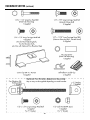
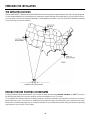
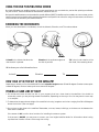
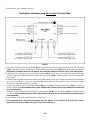
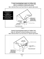
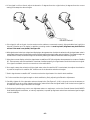
Panasonic
Installation Manual
TA-DA2420
for
DIRECTV PLUS ™ Satellite Dish Antenna
or
DIRECTV PARA TODOS ™ Satellite Dish Antenna
INTRODUCTION
This antenna system, with the equipment supplied, can receive signals simultaneously from satellites located at 101°
and 119° West longitude orbital locations. This antenna system also has a reserved position for a satellite located at
110°W for additional services. If such services are offered in your local area, you will be notified.
The installation procedures listed in this manual require basic knowledge in construction, assembly and wiring. In order
to safely install this antenna system, you must be able to perform the following skills:
• Use hand tools for assembly.
• Drill and seal holes in mounting surfaces.
• Use a bubble level to plumb the mast. (Critical
alignment - See Figure 2B.)
• Use a compass and inclinometer or protractor to determine clear line of sight to satellite.
• Install and run coaxial cables through the home from the antenna to the receivers.
• Climb ladders or roofs to mount and wire the antenna.
• Know local and NEC grounding codes. (The National Electric Code is published by the National Fire Protection
Association, 1 Batterymarch Park, Quincy, Massachusetts, 02269-9959 and may be available at your local public library.)
If you feel this installation is beyond your experience and skill level, then contact the store where the system was purchased for advice on professional installation services in your area.
WARNINGS
Local building and electrical codes (see latest revision of National Electrical Code) require proper
grounding of the antenna mount and coaxial cables. Improper installations may seriously damage
the equipment or the building and cause injury or death to you. Contact a licensed inspector or
electrician in your area for assistance.
WATCH OUT for power lines which may be overhead, buried underground and/or hidden behind
walls. Take extreme care to avoid contact with any power lines with ladders, satellite system parts
or tools during the installation to avoid serious injury or death.
TOOLS REQUIRED
• #1 Phillips Screwdriver
• 5/16 Hex Socket or Spintite
• 7/16 Hex Wrench open or combination end
• Electric Drill & bits
For Service Assistance, please call:
1-888-726-2377 in USA
(787) 750-4300 in Puerto Rico
• Bubble Level
• Compass With Degree Scale
TQB2AA0368
Printed in USA
• Inclinometer or Protractor
-1-
HARDWARE SORTER
Unpack and identify parts using figures in manual. Read manual thoroughly before beginning installation.
-2-
HARDWARE SORTER (continued)
-3-
MOUNTING LOCATIONS
Typical mounting locations are shown below. The mounting surface must be solid and rigid to prevent the antenna from
moving during windy conditions.
When attaching to wood framed structures, use the center holes on the mounting base foot to fasten onto the center of
a stud or rafter.
When attaching to masonry structures, use the four outside corner holes in base foot and four appropriate ¹⁄₄"
double-expansion anchors or toggle bolts with flat washers (not included).
When using an optional accessory 1.66 O.D. steel ground mount pole (not included), dig a 12" diameter hole 36" deep
for the pipe. CAUTION: Make certain the area is free of underground utilities before digging. Place flattened end
of pipe in concrete to prevent rotation and attach required ground wire to punched hole. The pipe should extend at least
30" into the concrete pier. (Refer to detailed installation instructions included in your optional pole mounting kit.)
WALL MOUNTED
RAIL MOUNTED
POLE MOUNTED
Requires optional mount kit
CHIMNEY MOUNTED
Requires optional mount kit
-4-
PREPARING FOR INSTALLATION
THE SATELLITE LOCATIONS
The two main DIRECTV satellites are located 22,000 miles above the equator at approximately 101° and 119° west longitude.
To look at these satellites if you live in Miami, you must have a clear line of sight to the Southwest; if you live in San Francisco,
you must have a clear line to the South-Southeast. (110°W satellite not shown. If services from 110°W satellite are offered
in your local area, you will be notified.)
FINDING THE DISH POINTING COORDINATES
Finding the dish pointing coordinates for your location includes presetting the azimuth, elevation, and tilt. This is done
by following the directions from your satellite receiver that appear on your TV screen.
To accomplish this, make sure that your satellite receiver is properly installed to your television so that you can see the
menu directions on your TV screen. Your satellite receiver does not need to be connected to your antenna for this step.
See the User’s Manual that came with your satellite receiver for more information about finding the antenna’s pointing
coordinates for your site ZIP Code number.
-5-
USING THE DISH POINTING MENU SCREEN
By simply following your satellite receiver’s on-screen menu feature, you can obtain the precise dish pointing coordinates
for your location. These coordinates include Azimuth, Elevation and Tilt.
Because this satellite antenna can be used with several different DIRECTV satellite receiver models, we can not show you the
specific instructions for obtaining dish pointing information here. Specific instructions for using on-screen menus can be found
in the manual that came with your satellite receiver.
RECORDING THE COORDINATES
When you have obtained the coordinates, record the Azimuth, Elevation, and Tilt numbers below.
Azimuth is the side-to-side direction
that the dish is pointed.
Elevation is the up/down angle that
the dish is pointed.
Tilt is the circular rotation of the
dish itself, like a steering wheel.
Write down your site information here:
Azimuth
Elevation
Tilt
HOW HIGH UP IN THE SKY IS THE SATELLITE?
Depending on where you live, the satellite will be at an elevation angle between 30 and 60 degrees. Southern states point
toward 60 degrees; northern states point more toward 30 degrees.
FINDING A CLEAR LINE OF SIGHT
1. Go outside and locate at least one site on your property that has a clear view to the satellites. You should be
reasonably certain you are pointing toward the satellites, depending on where you live. You may want to use a map
or a compass.
2. To determine the approximate height of the satellite in the sky, imagine a vertical arc ranging from 30 to 60 degrees
above the horizon. (See next page.)
3. Do you have a clear view to the satellites? Remember, no trees, leaves, buildings, or windows can be between the
dish and the satellites.
If the answer is NO, look for other locations for installing the antenna system.
If the answer is MAYBE, you may want to contact your local digital satellite dealer for information about having
a professional installer conduct a thorough site survey.
-6-
PRECISE SITE SURVEY
Based on your general site survey, you probably already know where you want
to mount your dish, but it’s a good idea to follow the procedures outlined in this
section in order to make sure that your site selection is a good one.
1. Go outside to your install site and hold a compass flat in the palm of your hand.
Hold your hand still until the needle stops moving (the dark or colored half of
the compass needle always points North).
2. Rotate the compass so that the “N” (for North) is directly under the dark part
of the compass needle. Your compass is now aligned with North. The marks
around the outside edge of the compass represent the azimuth degrees you
will point your antenna to.
3. Locate the tick mark on the compass edge that corresponds to the azimuth
number you wrote down. This is the direction of your azimuth setting (the
direction the dish will need to be pointed to receive signals from the satellites).
Pick a landmark or lay down a stick in that direction for reference from the
mounting location.
Ti p
Try to keep the compass away
from any metal objects. Metal
objects can cause inaccurate
compass readings.
4. Raise your arm to approximately the elevation angle recorded earlier to make
sure that there are no obstructions in the signal path. Use an inclinometer or
protractor to more accurately estimate the elevation angle.
WARNING
5. Repeat this survey in several places on your property if necessary until you
find the best mounting location.
From this rough sighting, allow plenty of clearance for the final alignment.
Remember trees grow up and out, which may possibly block the signal in
the future.
-7-
Do NOT install the dish near
power lines, electric lights or
power circuits. Contact with
power lines, lights or power
circuits may be fatal. It is
strongly recommended that the
dish be located more than 20
feet from overhead power lines.
ANTENNA MAST MOUNTING AND ON-THE-GROUND DISH ASSEMBLY STEPS
In order to make assemby easier and safer for you and to avoid losing hardware, it is recommended
that much of the assembly work be done on the ground in a clear area. More importantly, to simplify satellite alignment, the permanent tilt and preliminary elevation adjustments should also
be performed on the ground.
IMPORTANT! Some bolts may not fit into holes of painted metal parts due to an accumulation
of paint in the hole. This is not a product defect, but is a result of normal variation in the painting process. If you are having difficulty installing a bolt, tap the head of the bolt lightly with
a hammer to remove this paint and assemble the bolt.
1. On the universal mount assembly, insert (2) ¹⁄₄" x ¹⁄₂" long carriage bolts through the mast and bracket slot and capture
with an external tooth washer and flange nut. Install a #10 self-tapping screw for ground wire attachment. See Figure 1.
FIGURE 1
2. After the mounting location is determined, drill mounting holes in the structure to match the Universal Base Bracket.
IMPORTANT! Take time to plumb the top straight section of the mast so it is vertical in
all directions before drilling the holes in the structure and after the Universal Mount
is installed. If the mast is not plumb, alignment to the satellite will be very difficult. See
Figure 2B.
• When attaching to wood framed structures, use the two center inside holes in the mounting base. They must be aligned
on the centerline of the stud or rafter. Attach with two ⁵⁄₁₆” x 3" lag bolts and flat washers (not included) screwed
into a ⁷⁄₃₂” diameter pilot hole in a solid wood structural member. Apply silicone sealant around bolt entry to prevent
water from entering the holes. See Figure 2.
• When attaching to masonry structures, use the four corner outside holes in base bracket and four appropriate ¹⁄₄"
double-expansion anchors or toggle bolts with flat washers (not included). See Figure 2A.
-8-
Critical Alignment
FIGURE 2
WOOD STRUCTURES
FIGURE 2A
MASONRY STRUCTURES
FIGURE 2B
3. On clamp/mount assembly, install (2) ⁷⁄₈" long azimuth clamp bolts and flange nuts as shown in Figure 3. Do not tighten
at this time.
4. Install a 1/2” long carriage bolt through the square hole in the clamp tab and elevation adjustment slot. Capture with
a flat washer and ESNA locknut. Tighten nut and then loosen 1/3 turn. See Figure 3. For units NOT equipped with fine
elevation adjustment, skip to Step 7.
5. For Models equipped with Fine Elevation Adjustment Option: Assemble long fine tune elevation bolt to the Az/El mount
elevation bracket with an embossed elevation scale using a 1/2” long carriage bolt and ESNA locknut. Tighten and then
loosen 1/3 turn to allow bracket to pivot. See Figure 4.
FIGURE 3 - Az/El Assembly - Opposite side of Figure 4
FIGURE 4 - Az/El Assembly - Optional Fine Elevation Adjust.
6. Thread the L-bracket onto the long fine elevation adjustment bolt approximately one inch. Then assemble the L-bracket
to the elevation slot with a 1/2” long carriage bolt passing through the square hole in the clamp tab, elevation adjustment slot, and L-bracket. Capture all with an ESNA lock nut. Tighten nut and then loosen 1/3 turn. See Figure 4.
7. If the Fine Elevation bolt is not equipped on your model, install the second ¹⁄₂" long carriage bolt through square hole
in the clamp tab, then through the elevation adjustment slot on side with embossed elevation scale and capture with
a flat washer and ESNA locknut. Tighten nut and then loosen ¹⁄₃ turn. Similar to Figure 3.
-9-
8. Attach the antenna to the tilt slots on the clamp/mount assembly with two 1-3/4” long carriage bolts, flat washers
and ESNA locknuts, making certain the center pin on the antenna is in the mating hole in mount tab before tightening. See Figure 5.
FIGURE 5A
FIGURE 5
9. Make the PERMANENT TILT adjustment . Remember, this is the value listed for your site location which was determined
from your satellite receiver menu screen. (Do not use numbers from any other sources.) Be sure both bolts in the slots
are 1/3 turn loosened from tight during adjustment. After adjustment, securely tighten after the desired tilt scale number
is aligned with the molded indicator line on the antenna. See Figure 5A..
IMPORTANT! DO NOT MAKE ANY FURTHER ADJUSTMENTS TO THIS TILT SETTING.
FIGURE 6A
FIGURE 6
10. For models with fine tune adjustment, make the initial elevation adjustment from the value listed for your site location which was determined from your satellite receiver menu screen. Be sure both bolts in the slots are 1/3 turn loosened
from tight. Adjust the elevation until the white painted clamp tab edge indicator aligns with the desired elevation
value on scale. See Figures 6 and 6A..
11. If fine elevation adjustment hardware is not included with your dish model, then adjust elevation as per Figure
6A. Tighten elevation bolts on both sides.
-10-
FIGURE 7
FIGURE 8
12. Attach the rectangular feed tube to the antenna socket. Make certain the large round hole for the spacer is positioned
as shown in Figure 7. Tighten bolt while holding nut.
13. Attach the LNB Adapter to the feed tube with #8 hex insert nut and 1" long Phillips head screw. See Figure 7. Do not overtighten to the point of deforming the feed tube and the LNB Adapter.
14. Install plastic Cover Clip in the Plastic LNB Adapter in the empty space between Sat A and Sat B dual LNBs before mounting LNBs. See Figure 8.
15. Before making any wire connections, read “Connections”, Page 18. The next steps involve making the coaxial cable
interconnections between the LNBs, multiswitch and the satellite receivers. First, choose one of the mounting location
options for the multiswitch listed below that best fits your installation. Use approved installation kits with high quality,
low loss RG6 coaxial cable to insure the best performance under all conditions. All coaxial cables must be grounded
outside at the point of entry. Contact a licensed inspector or electrician in your area for assistance. General grounding requirements are outlined in Figures 11 and 12.
MULTISWITCH LOCATION OPTIONS:
• Option #1: Mounting a weatherproof multiswitch to the back of the antenna as shown in Figure 9. This location
is simplest for installations that use one receiver since only one cable enters the building. If this option
is selected, connect the LNBs to the multiswitch per the following instructions while on the ground with
coaxial cables. Depending on your model, a 4-cable set may be included for ease of installation.
• Option #2: Mounting the multiswitch inside the house. This option provides the best weather protection and may
provide the easiest access for future wiring changes, such as adding additional satellite receivers.
• Option #3: Mounting the weatherproof multiswitch under the building eaves at the point of cable entry. This
option provides excellent weather protection to the wire connections and the switch. It eliminates the coaxial ground
blocks since the multiswitch also serves as a grounding block for the four LNB cables connected to it.
NOTE FOR OPTIONS #1 and #3: Typically in a single family home, the RG6 cable for the supplied 4 x 4 mulitswitch does
not exceed 100 feet from the satellite receiver(s) to the LNBs. For installations where each RG6 cable
run from the satellite receiver(s) to the LNBs exceeds 100 feet, such as often encountered in a commercial or multi-dwelling
building, it is recommended that you use an AC-powered multiswitch (not supplied). An AC-powered multiswitch
powers the multiswitch and the LNBs directly from an AC/DC power module so that the
satellite receiver is capable of driving a longer RG6 cable. Contact Channel Master Technical Service for an
Application Note concerning such installations. Other manufacturers may offer similar products.
16. Even though all the above mutiswitch location options are used by installers, this manual will concentrate on option
#1. If an installer chooses to install the multiswitch in the house or at the point of entry to the house, then cables of proper
lengths must be cut. To prevent corrosion, weatherproof outdoor connectors with rubber o-rings must be used for
all outdoor connections. See Figures 11 and 12 for general wiring diagrams.
-11-
ON-GROUND INSTALLATION WITH MULTISWITCH ON BACK OF DISH - OPTION #1
1. To install the outdoor multiswitch to the back of the antenna, use the #8 self tapping screws and washers
provided in the multiswitch carton. CAUTION: Use a hand tool to tighten the screws until the face of the screw head is
evenly touching the multiswitch mounting lug – then tighten ¹⁄₄ turn more. You will also need 4 cables to make the connections between the multiswitch and the LNBs. A set of gray cables is provided for Option #1, in most antenna models.
The cables are routed from the multiswitch through the feed tube to the LNBs as shown in Figure 10. The cables should
be dressed as shown using the cable clips provided in the hardware bag. IRD cables should be routed underneath the
gray cable set as illustrated in Figure 9 (one IRD cable shown in black). With the exception of the IRD cable, it may be
easier to perform much of this installation on the ground.
FIGURE 9
-12-
2. Review Figure 10 for multiswitch wiring.
Multiswitch Installations Using Sat A & Sat B (Two Dual LNBs)
FIGURE 10
3. Pass one end of two coaxial cables (labeled “Sat A” on both ends) through the rectangular feed tube on the side marked
“Sat A”. Then attach them to the LNB that will be mounted in the position marked “Sat A” at the end of plastic LNB Adapter.
IMPORTANT! If labeled cables are not supplied, then mark two cables on both ends “Sat A” with masking tape.
4. Repeat Step 3 for inserting the two coaxial cables (labeled “Sat B” on both ends) in the other side of the feed tube and
connect to the second LNB that will be mounted in position marked “Sat B”. Tighten all cable connectors on both LNBs.
See Figure 8.
5. Carefully push the LNBs and attached cables into the LNB Adapter all the way flush with the edge of the LNB Adapter
and secure with #8 insert nut and 1” long #8 phillips head screw and then tighten screws. See Figure 7. Slight
movement of LNBs after tightening is normal.
6. Connect opposite loose end of the cables labeled “Sat A” from “Sat A” LNB to the multiswitch “Sat A” terminals as
shown in Figure 10. It does not matter which “Sat A” labeled cables connect to 13V or 18V multiswitch terminals–they
are interchangeable.
7. Repeat for connecting opposite loose end of the cables labeled “Sat B” to the multiswitch “Sat B” terminals as shown
in Figure 10. It does not matter which “Sat B” labeled cables connect to 13V or 18V multiswitch terminals. They are
interchangeable.
8. Install weather caps on all unused multiswitch connectors.
9. This completes the On The Ground Assembly work for Option #1. For Options #2 and #3, follow similar
applicable procedures in addition to Figures 11 and 12 as references.
-13-
General Grounding Requirements for Outdoor Unit
Option #1 Multiswitch located on back side of dish
Option #2 Multiswitch located inside building
Refer to National Electric and Local Codes for complete requirements.
The National Electric Code
is published by the
National
Fire Protection Association
1 Batterymarch Park
Quincy, Massachusetts, 02269-9959
and may be available at
your local public library
FIGURE 11
General Grounding Requirements for Outdoor Unit
Option #3 Multiswitch located at building entrance point
Refer to National Electric and Local Codes for complete requirements.
FIGURE 12
-14-
GENERAL GROUNDING REQUIREMENTS
The universal mount and coaxial cables must be properly connected to grounding electrode(s) per National Electrical
Code (NEC) Sections 810 and 250, and per your local codes. For the three multiswitch options described, please see
top-level general grounding diagrams in Figures 11 and 12.
MOUNTING THE ANTENNA ASSEMBLY TO MAST
1. Slide the clamp/mount on the antenna assembly onto the Universal Mount mast and loosen/tighten the (2) azimuth
clamp bolts (see Figure 5A) and the elevation pivot bolt (See Figures 3 and 4) just enough that the antenna
assembly is set into the mast all the way until the top of the mast meets the elevation pivot bolt/spacer.
2. Tighten only the elevation pivot bolt. This will not restrict the azimuth (horizontal) rotation. If, after the antenna
assembly is already mounted on the antenna mast, and the elevation adjustment screws are loosened or the tilt adjustment screws are also accidentally loosened, tightening the elevation pivot bolt will prevent any extra free play of
the Az/El mounting assembly. See Figures 3 and 4.
3. Install quality RG6 cables from the satellite receivers to the multiswitch. You may want to install one receiver first
until the satellite signals are acquired and fine tuned. Routing of receiver cables, if the multiswitch is mounted at
the back of the dish, is shown in Figure 9.
-15-
ACQUIRING AND FINE TUNING THE SIGNAL
Now that you have installed the satellite antenna and routed all of the cables, it’s time to acquire and fine tune the
signal. Before you begin, you may want to go outside and double-check the azimuth, elevation, and tilt settings on the
dish to make sure they correspond to the on-screen coordinates given by the satellite receiver.
• Make sure that the elevation indicator is aligned with the edge of metal, not the washer or bolt, per Figure 6A.
• Make certain the antenna mast is plumb, per Figure 2B.
• Use a compass to verify that the azimuth setting on the dish is correct and no obstacles are
between the dish and satellites.
STEP-BY-STEP INSTRUCTIONS FOR ACQUIRING AND FINE
TUNING THE SIGNAL
1. Read the instruction manual that came with your satellite receiver or set-top
converter to determine how to access the on-screen signal meter.
The signal meter shows you when you have locked onto a satellite’s broadcast signal, and gives you the signal strength. It is easiest to use the signal meter with the
help of another person to relay signal strength values to you, or by moving the TV
displaying the signal meter so that it is easily viewed at the point of installation.
NOTE: Satellite A (101˚) has 32 authorized transponders from 1 to 32; all are
active. Therefore, the on-screen signal meter may be tuned to any of the 32
transponders for the initial dish antenna adjustment.
Satellite B (119˚) has 11 authorized transponders from 22 to 32; but a few of these
may be reserved for upcoming programming expansion. Tune your on-screen
signal meter to transponders 23, 25, 29 or 31 for the initial dish antenna
adjustment.
2. Make sure that you select the correct type of dish (oval, 2 LNBs) on your receiver
menu. The signal meter will give you the pointing coordinates for your antenna,
and values will depend on the type of antenna you have selected. Failure to select
the correct dish will result in wrong pointing angles as well as the inability to receive
certain programming. Consult your receiver manual for additional detail.
3. Access the signal meter. Set signal meter to the 101° satellite (this might also be
represented on-screen as “Satellite A”). At this point you will probably not have
a signal.
Point center of the antenna
to the exact azimuth direction
according to your compass
a. Using a compass, point the antenna to one side (left or right by a few degrees) of
the azimuth value for your location.
b. Sweep the antenna towards and through the azimuth point by moving the dish in
approximately 3 degree increments. Pause for a couple of seconds and wait for an
updated value from the signal meter. When the signal is found and the signal meter
is locked onto a signal, go to step 4.
c. If, after sweeping the antenna completely left to right or right to left and
the satellite signal is not found, adjust
the elevation +2 degrees and sweep
the azimuth again. (Do not change tilt
alignment setting.)
-16-
Maximum Signal
Strength
While the maximum signal
strength is 100, the signal strength
you achieve will most probably
be less. Although there is no
difference in picture quality above
signal strengths of 60, the higher
the signal, the less likely you are
to experience signal outages
during adverse weather. For this
reason, it is important to obtain
the strongest signal possible.
Ti p
If your receiver is not equipped
with the audible tone feature, you
may have a friend watch the
signal meter and relay the
strength reading to you.
Ti p
If your receiver is equipped with
the audible beep tone feature,
make sure you have the strongest
possible signal(s) by moving the
dish until you get the highest
pitched beep tone. Consult your
receiver manual for detail.
d. If the signal is still not found, adjust the elevation -2 degrees from the original value (-4 degrees from the current
setting) and sweep the azimuth again.
e. If the signal is still not found, check to make sure the cables are connected correctly. Using a bubble level, verify the
Azimuth, Elevation and Tilt angles, in addition to making certain the mast is plumb. (Alignment may be difficult to
achieve if the mast is not plumb.) See Figure 2B.
4. With signal meter locked onto a signal and displaying a value greater than 0, adjust the azimuth until the signal meter value is
maximized. Make a note of the elevation and the azimuth angles where signal meter was the highest. (The elevation angle can
be read from the scale, the azimuth angle can be noted by marking the mast and antenna bracket using a pencil.
5. Using the on-screen display, switch the signal meter to satellite at 119˚ (this might also be represented on-screen as “Satellite
B”). If the antenna, mast and multiswitch have been installed properly, the signal meter should be locked onto a signal.
If no signal is available, check the connections to the multiswitch.
6. Once again, sweep the azimuth until the signal meter value for satellite 119˚ is maximized, then adjust the elevation
to peak the reception for satellite 119˚. Make a note of the elevation and azimuth angles.
7. Switch signal meter to satellite 101˚ to make sure that the signal meter is locked for both satellites.
7a. Further maximize the signal strength on both satellites by finely adjusting the Elevation Adjustment.
8. Carefully tighten all of the elevation and mast clamp bolts, (See Figures 3, 4, 6A), trying not to move the antenna on
the mast while you do so. After tightening the bolts, make certain that the signal meter is still locked onto a signal for
all satellites and the signal value has not changed.
9. Professional installers may want to use alignment meters or equipment, such as the Channel Master Model 1006IFD
Dual Satellite Signal Level Meter, or industry equivalent, to speed up alignment and achieve maximum signal strength
on both satellites.
-17-
TROUBLESHOOTING FOR MULTISAT DISH ANTENNAS
Connections
1. IMPORTANT: Before installing coax cable, visually inspect the inside of each cable connector to make sure
that there is no dirt, moisture or any other foreign material in the connector. Also check to make sure that
the aluminum cable shielding foil or braid is not touching the copper center conductor. After inspecting the
inside of the connector and making any corrections, make sure that the copper center conductor is straight
and centered in the end of the connector.
2. Make sure that the two “Sat A” cables that are included with your antenna are marked ‘Sat A” on both ends.
The two “Sat A” cables connected to the “Sat A” dual LNB must go to the two “Sat A In” connectors at the
multiswitch. Any one of the two “Sat A” cables can go into any one of the two “Sat A In” connectors at the
multiswitch.
3. Make sure that the two “Sat B” cables that are included with your antenna are marked “Sat B” on both ends.
The two “Sat B” cables connected to the “Sat B” dual LNB must go to the two “Sat B In” connectors at the
multiswitch. Any one of the two “Sat B” cables can go into any one of the two “Sat B In” connectors at the
multiswitch.
4. “Out 1”, “Out 2”, “Out 3”, and to “Out 4” are all identical multiswitch outputs to the satellite receivers.
5. RG6 cable must be used for installation from the dish to the receivers to achieve optimal signal levels. RG6 cable
have less signal attenuation than the existing RG59 cables sometimes found in a user’s home.
6. Exisitng TV-specific components, such as TV splitter, etc. may not perform properly. When unsure of
installation, remove such components and reduce the installation to the basic connections called out in the
installation manual.
7. Make sure the satellite receiver operating manual is properly followed, in addition to the dish antenna installation manual. Make sure the DIRECTV Access Card is fully inserted in the card slot of the receiver.
8. Make sure all the cable connections are securely tightened/fastened from the LNBs to the multiswitch, from the
multiswitch to the grounding block (s) and then to the “Satellite In” jack at the receiver. This is also critical for
preventing any cable conductor corrosion in the future.
Pointing
1. Make sure the correct numbers, by Zip code, are used for the “tilt” (dish angle rotation), “elevation” (vertical
up or down) and “azimuth” (horizontal left or right) for the installation location.
2. Before the dish antenna is moved to the antenna mast, use the receiver’s on-screen pointing menu to fix the “tilt”
setting by following the procedures found in the dish antenna installation manual. Once the signal is acquired,
the Elevation Adjustment setting may need to be fine tuned to maximize the signals.
3. The most critical procedure is the proper plumbing of the dish antenna mast. It must be plumb and level,
otherwise the acquiring of both satellites is difficult and even if the satellites are acquired, it may not be an
optimum setting and is therefore prone to rain, snow, wind outages.
4. When using a compass to set initial “azimuth” as indicated by the receiver’s dish-pointing menu, make sure the
compass is not falsely deflected by any nearby metal object(s).
5. Make sure there are no obstructions between the dish antenna and the satellites, for the settings of “tilt”,
“elevation” and “azimuth” at the installation location. Trees may have to be trimmed periodically if they grow
too close.
6. Slowly rotating the dish antenna left and right of the required “azimuth” until the receiver’s on-screen meter
indicates strong signals for both satellites.
-18-
TROUBLESHOOTING FOR MULTISAT DISH ANTENNAS (continued)
7. If all have been done correctly but the system is still not aligned optimally, slightly change the “elevation”
adjustment of the dish antenna and repeat the procedure. The “tilt” must be set for a given installation
location by Zip code, per receiver’s on-screen menu, and must not be changed.
Temporary Loss of Signal
1. If there is an unusually heavy rainfall in the installed area, the signal may be lost temporarily. An optimally aligned
dish antenna minimizes the chances of “rain fades”.
2. Make sure the dish antenna is mounted securely to prevent it from being permanently blown out of the correct
position in heavy wind.
3. Until it is removed, heavy snow accumulation on the LNBs or the dish may reduce the satellite signal strength.
4. A dish antenna with tree foliage in the line of sight to the satellite may have a good picture on a clear day,
but no picture with a slight rain.
Receiver
Your receiver requires adequate ventilation. It should not be stacked with other entertainment units such as VCR
and stereo. If stacking is needed, the satellite receiver should be on the top of the stack. Otherwise the receiver
may fail, which could lead to troubleshooting in the wrong area.
Installed System
The 4x4 multiswitch, which is supplied with this system, is powered directly from the satellite receiver(s), thus offering greater flexibility in locating the multiswitch as described in the preceding pages. Nevertheless, the longer the
cable length, the higher the DC and the signal attenuation. Though rarely encountered in a single family home, cable
lengths longer than 100 feet, from the satellite receiver to the LNBs, should be avoided.
For installations where the RG6 cable run from the satellite receiver(s) to the LNBs exceeds 100 feet, such as often
encountered in a commercial or multi-dwelling building, it is receommended that you use an AC-powered multiswitch
(not supplied). An AC-powered multiswitch powers the multiswitch and the LNBs directly from an AC/DC power
module so that a satellite receiver is capable of driving a longer RG6 cable. Contact Channel Master Technical Service
for an Application Note concerning such installations. Other manufacturers may offer similar products.
DIRECTV, DIRECTV PLUS and DIRECTV PARA TODOS are trademarks of DIRECTV, Inc., a unit of Hughes Electronics Corporation,
and are used with permission.
-19-
NOTES
-20-


![588-589-00a [Converted]](http://vs1.manualzilla.com/store/data/005638396_1-02d08bb06dde3fa2099be559e669b8e9-150x150.png)
