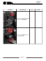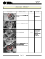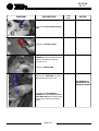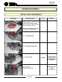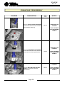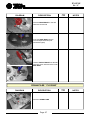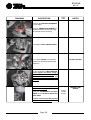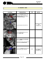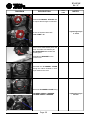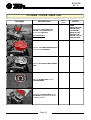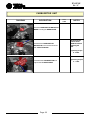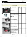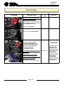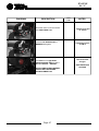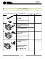
1
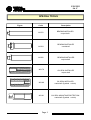
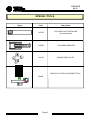
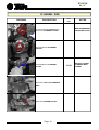
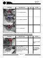
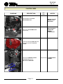
SERVICE MANUAL
S6-C COMPETITION
50cc – 2 stroke - liquid cooled
ENGINE
S6 /C
INDEX
TECHNICAL SPECIFICATIONS
2
SPECIAL TOOLS
3-4
PERIODIC MAINTENANCE
5
LUBRICANTS
6
TROUBLESHOOTING
7 - 14
TIGHTENING TORQUE TABLE
15
ENGINE DISASSEMBLY
16 - 24
ENGINE REASSEMBLY
25 - 37
SPECIAL 3-SHOE CLUTCH DISASSEMBLY/REASSEMBLY
38 - 39
SPECIAL 3-SHOE CLUTCH ADJUSTMENT PROCEDURE
40
ENGINE COMPONENT INSPECTION AND SERVICE
41 - 43
GENERAL PARTS LIST + EXPLODED VIEW TABLES
xx
Page 1
ENGINE
S6 /C
TECNICAL SPECIFICATIONS
SPECIFICATIONS
CYCLE .........................................................
- 2 stroke
Nr. of CYLINDERS .......................................
-1
DISPLACEMENT..........................................
- 49.908 cc.
BORE AND STROKE
- 39 X 41.8
mm. ............
CYLINDER MATERIAL .................................
- Aluminium with Ni / Si carbide coating
COMPRESSION RATIO ................................
- (15.5 ±0.3) : 1
SPARK PLUG ..............................................
- CHAMPION C53
TIMING SYSTEM ..........................................
- Reed valve with 4 carbon fibre flaps
MAX. R.P.M. ..................................................
- 14500 (rpm) MAX
CARBURETOR ............................................
- 12/14/19 mm diameter
INTAKE MANIFOLD .....................................
- Adjustable
FUEL ............................................................
- EURO UNLEADED NC 623/02 - R.O.N. 95
LUBRICATION OIL MIXER TYPE .................
- 2% AGIP 2T CITY
LUBRICATION WITH OIL PUMP ..................
- On request
IGNITION ......................................................
- Electronic with microchip
PRIMARY DRIVE GEAR ...............................
- Straight-tooth gears Z 14/59
.....................................................................
with safety coupling
.....................................................................
Ratio 1:4,21
SECONDARY DRIVE GEAR .........................
- Sprocket Z 10 or Z11
.....................................................................
Chain type 1/2 x 3/16 roller 7.75
CLUTCH ......................................................
- Automatic centrifugal clutch in oil bath
.....................................................................
Adjustable
TRANSMISSION GEAR OIL .........................
- SAE 20 W quantity 250 cc
STARTER ......................................................
- Kick starter
COOLING ......................................................
- With liquid pump
Page 2
ENGINE
S6 /C
SPECIAL TOOLS
Figure
Code
143176
143154
Description
BEARING INSTALLER
output shaft
BEARING INSTALLER
crankshaft
143156
BEARING INSTALLER
output shaft
143179
OIL SEAL INSTALLER
output shaft
143180
OIL SEAL INSTALLER
crankshaft (flywheel + clutch)
143181
OIL SEAL MOUNTING PROTECTION
crankshaft (flywheel + clutch)
Page 3
ENGINE
S6 /C
SPECIAL TOOLS
Figure
Code
Description
143155
OIL PUMP SHAFT INSTALLER
(pre-assembled)
140558
FLYWHEEL REMOVER
143162
CRANKCASE PULLER
SPECIAL CLUTCH ADJUSTMENT TOOL
143294
Page 4
ENGINE
S6 /C
PERIODIC MAINTENANCE
RUNNING-IN RECOMMENDATIONS:
During the running-in period, i.e. for approx. the first 500 km on the road, please note as follows:
- Do never run the engine at maximum revolutions.
- Do never keep the vehicle at maximum speed.
- Do not keep the engine at idle speed for longer time.
FIRST MAINTENANCE SERVICE:
to be carried out after 500 - 600 km.
- Replace the engine oil
- Check the carburation and adjust if necessary
- Check the tightness of nuts and bolts.
(See table “tightening torques” pag. 15)
Page 5
ENGINE
S6 /C
LUBRICANTS
N.B.
Use original MORINI FRANCO MOTORI spare parts only
RECOMMENDED LUBRICANTS / ADHESIVES
DESCRIPTION
CHARACTERISTICS
Transmission oil
AGIP RADULA 68 SAE 20W
Assembly of various parts
Special assembly
GR/SM2 GREASE
GRAPHITISED MOLYCOTE type GREASE
Thread-locking glue
LOXEAL 82-21
Clamping glue
LOXEAL 83-54
N.B. TRANSMISSION OIL LEVEL CHECK
Remove the oil filler cap on the clutch cover and check the transmission oil level
through window.
Page 6
ENGINE
S6 /C
TROUBLESHOOTING
The following flow charts give a general outline of the causes and effects when the engine is not
running correctly.
Descriptions of solutions for a specific cause are general; for more details the reader should
consult the disassembly-reassembly manual.
LEGEND OF SYMBOLS
EFFECT (fault noticed by the user)
Possible CAUSE of the fault
Possible general SOLUTION to the fault
Page 7
ENGINE
S6 /C
Starting problems
Faulty spark plug
or wrong spark plug
heat rating
YES
Check spark plug and
replace if necessary.
NO
YES
Start the engine with the
throttle fully open.
Engine flooded
NO
Remove the spark plug,
rev the engine, install a
dry spark plug and restart
the engine.
Sparking starts at
high r.p.m.
YES
Page 8
NO
The engine
starts
Replace the ignition coil
ENGINE
S6 /C
Maximum indicated running
speed cannot be reached
Soiled or
clogged
filter
YES
Disassemble, wash sponge with a
50% solution of petrol and 2T oil;
leave to dry. Clean the filter box
using compressed air; reassemble.
NO
Silencer
obstructed
YES
Check the silencer for clogging.
Replace if necessary.
NO
Cylinder
exhaust port
soiled with
carbon
deposits
YES
Disassemble the cylinder and check
that the exhaust pipe is clean. If the
exhaust pipe is partly obstructed by
carbon deposits, clean it thoroughly
using a scraper.
NO
Poor
compression
YES
Page 9
Disassemble the cylinder head,
cylinder and piston.
Remove the piston rings, place
them in the cylinder liner and check
the amount of wear.
Replace if excessively worn.
ENGINE
S6 /C
Poor acceleration / pickup
Clutch
YES
Check the cluth shoe thickness and
the clutch springs for stretching.
If excessively worn they should be
replaced.
NO
Irregular
acceleration
YES
Page 10
Check the exact number of turns
of the air adjusting screw on the
carburetor.
ENGINE
S6 /C
Incorrect idling speed
Idling speed
too high or
too low
YES
YES
NO
False air
intake from
carburetor
manifold
YES
Disassemble the carburetor and
clean all parts (nozzles, throttle valve, jet needle, float chamber and
body) with solvent and dry by using
compressed air.
Check the integrity of the
carburetor manifold gaskets.
YES
Check the integrity of the rubber
coupling sleeve that connects the
carburetor and air filter box .
YES
Check the reed valve gasket.
YES
Check the integrity of the
crankshaft oil seals. Replace
even if only slightly damaged.
NO
False air
intake
from engine
crankshaft
oil seals
Adjust the RPM of the idling speed
(with engine warm) by adjusting the
screw on the throttle valve of the
carburetor.
Page 11
ENGINE
S6 /C
Noisy engine
Incorrect
transmission
gears
assembly
YES
Check the assembly of all gears and
parts of the transmission.
YES
Check the tightening torque of the
clutch nut.
NO
Loose
transmission
nut
NO
Transmission
noise and rear
wheel drag at
idling speed.
YES
Page 12
Check the clutch unit
ENGINE
S6 /C
Noisy engine
Noisy gears
YES
YES
NO
Noisy
cylinder
unit
YES
Check the oil level.
Refill if necessary.
Check the teeth of the drive gears
visually.
Replace if signs of damage or
wear are evident.
Check the clearance between the
piston and the cylinder. If it does
not correspond to the prescribed
value, replace the cylinder and
piston.
NO
Noisy
crankshaft
bearings
YES
Page 13
BEARING INSPECTION
Rotate the bearing inner race by finger to inspect for abnormal play, noise
and smooth rotation while the
bearings are mounted in the
crankcase.
Replace the bearing if anything
unusual is found.
ENGINE
S6 /C
Smokey exhaust
Percentage of
mixer oil
YES
Replace the fuel in the tank with
new fuel mixed with 2% of the type
of oil indicated in the handbook.
YES
Check that the oil is 100%
synthetic for separate oil mixer
pump use.
NO
Mixer oil
NO
Carbon
deposits
YES
Disassemble the cylinder and
remove any carbon deposits;
check the silencer for clogging.
NO
Oil mixer
pump
YES
Page 14
Disassemble the oil mixer pump
and check the flow rate.
ENGINE
S6 /C
TIGHTENING TORQUES
DENOMINATION
TORQUE
(Nm)
Cranckcase bolts
10 - 12
Clutch cover bolts
10 - 12
Flywheel cover bolts
3-4
Carburetor manifold bolts
9 -10
Stator clamping bolts
3-4
Oil pump clamping bolts
5-6
Carburetor clamping screw
3-4
Kick starter lever bolt
8 - 10
Oil drain plug
8 - 10
Clutch nut
50 - 55
+ Loxeal 83-54
Flywheel nut
8 -10
+ Loxeal 83-54
Head nuts
12 - 14
Head clamping bolts
10 - 12
Pulley clamping bolts
3-4
+ Loxeal 83-54
5-6
+ Loxeal 83-54
Water pump rotor
Spark plug
20 - 25
Page 15
ENGINE
S6 / C
ENGINE DISASSEMBLY
CARBURETOR UNIT
DIAGRAM
DESCRIPTION
TOOL
CODE
NOTES
Disassemble the CARBURETOR
Loosen the SCREWS and remove the
CARBURETOR MANIFOLD
BEFORE LOOSEN
THE SCREWS
CHECK ACTUAL
MANIFOLD ANGLE
POSITION
THE MANIFOLD IS
COMPOSED BY 4
ELEMENTS.
Remove the CARBURETOR
MANIFOLD BASE including the
REED VALVE
Page 16
ENGINE
S6 / C
CYLINDER HEAD - CYLINDER - PISTON
DIAGRAM
DESCRIPTION
TOOL
CODE
NOTES
Remove the SPARK PLUG
Remove the 4 CYLINDER HEAD
BOLTS
Remove the 4 CYLINDER HEAD
NUTS
Remove the CYLINDER HEAD
Check the condition of the O-RING
(HEAD GASKET).
Replace if excessively worn.
Page 17
PAY ATTENTION TO
THE DOWEL PINS
ENGINE
S6 / C
DIAGRAM
DESCRIPTION
Disassemble the CYLINDER and
remove the CYLINDER BASE
GASKET
Page 18
TOOL
CODE
NOTES
ENGINE
S6 / C
FLYWHEEL SIDE
DIAGRAM
DESCRIPTION
TOOL
CODE
NOTES
MIND THE BRACKET
INSIDE THE COVER
Loosen the clamping BOLTS and
remove the FLYWHEEL COVER
Disassemble the FLYWHEEL
STATOR
Disassemble the FLYWHEEL
ROTOR
Remove the PULLEY CLAMPING
BOLT
Remove the DRIVEN PULLEY
Page 19
143151
ROTOR LOCK NUT
CLAMPED WITH
LOXEAL
ENGINE
S6 / C
DIAGRAM
DESCRIPTION
TOOL
CODE
NOTES
Remove the PUMP DRIVE BELT
Remove the SPECIAL SNAP RING
Remove the SPACER RING
The following operations can only be carried out after opening the crankcase
DIAGRAM
DESCRIPTION
Unscrew the WATER PUMP ROTOR
Remove the PUMP SHAFT UNIT
including the bearings.
The pump shaft seal ring must be
replaced by every disassembly.
The 2 bearing snap rings on the
water pump must be replaced by
every disassembly.
Page 20
TOOL
CODE
NOTES
BLOCK THE PUMP
SHAFT
PAY ATTENTION
TO THE SPACERS
BETWEEN THE
BEARINGS
ENGINE
S6 / C
CLUTCH SIDE
DIAGRAM
DESCRIPTION
Disassemble the CLUTCH
ADJUSTING PLUG
Remove the OIL DRAIN PLUG
(cross head)
TOOL
CODE
NOTES
ONLY IF CLUTCH
NEEDS TO BE
ADJUSTED
MAKE SURE TO
DRAIN THE
ENGINE
COMPLETELY
Loosen the clamping BOLTS on the
cover and remove the CLUTCH
COVER
Remove the SPECIAL FRONT
CLUTCH NUT and the
BELLEVILLE WASHER
Page 21
Compass tool CLAMPED WITH
LOXEAL.
ENGINE
S6 / C
DIAGRAM
DESCRIPTION
Disassemble the SPECIAL CLUTCH
and the 2.5mm SPACER RING
Remove the CLUTCH BELL and the
0.8mm SPACER RING
Page 22
TOOL
CODE
NOTES
ENGINE
S6 / C
CRANKCASE “OPENING”
DIAGRAM
DESCRIPTION
TOOL
CODE
Remove the cylinder STUD BOLTS if
necessary
NOTES
BLOCKED WITH
LOXEAL
Remove the 8 CRANKCASE BOLTS
Open the CRANKCASE
Remove the DOWEL PINS and the
CRANKCASE GASKET.
Remove the crankshaft if necessary
Page 23
143162
THE CRANKSHAFT
IS DRIVEN ONTO
THE BEARINGS.
OPEN THE
CRANKCASE FROM
FLYWHEEL SIDE
USING THE
PULLER TOOL
ENGINE
S6 / C
DIAGRAM
DESCRIPTION
TOOL
CODE
NOTES
Remove the OUTPUT SHAFT SNAP
RING
Remove the OUTPUT SHAFT
Inspect the OUTPUT SHAFT
BEARING for abnormal play and noise.
Replace the bearing if anything
unusual occurs.
Remove the SNAP RING
Remove the BEARING by using a
standard bearing remover set.
THE BEARING IS
DRIVEN INTO THE
BEARING HOUSING
To replace the CRANKSHAFT
BEARING and the OUTPUT SHAFT
ROLLER CAGE (flywheel side) follow
the same procedure as described
above.
Page 24
ENGINE
S6 / C
ENGINE REASSEMBLY
WATER PUMP PREASSEMBLY
DIAGRAM
DESCRIPTION
TOOL
CODE
NOTES
Preassemble the WATER PUMP
SHAFT UNIT by mounting the
components in the following order:
snap ring + bearing + spacer + bearing
and secure with the snap ring.
Insert the complete unit in the HALF
CRANKCASE FLYWHEEL SIDE
Insert the SPACER RING
Insert the SPECIAL SNAP RING
Insert the SEAL RING
Reassemble the
WATER PUMP ROTOR
Page 25
143155
THE SEAL RING
MUST ALWAYS BE
REPLACED WITH A
NEW ONE
Tightening torque
5 - 6 Nm +
Loxeal 83 - 54
ENGINE
S6 / C
CRANKCASE PREASSEMBLY
DIAGRAM
DESCRIPTION
Drive the OUTPUT SHAFT BEARING
into the half crankcase clutch side and
secure with the snap ring
TOOL
CODE
NOTES
143176
LUBRICATE THE
HOUSING
LEAVE THE PRINT
ON THE BEARING
VISIBLE
LUBRICATE THE
HOUSING
Drive the CRANKSHAFT BEARINGS
into the half crankcase clutch side and
into the half crankcase flywheel side.
143154
LEAVE THE PRINT
ON THE BEARING
VISIBLE
LUBRICATE THE
HOUSING
Drive the ROLLER CAGE OUTPUT
SHAFT into the half crankcase
flywheel side.
Page 26
143156
LEAVE THE PRINT
ON THE BEARING
VISIBLE
ENGINE
S6 / C
DIAGRAM
DESCRIPTION
TOOL
CODE
NOTES
TOOL
CODE
NOTES
Insert the DRIVE SHAFT in the half
crankcase clucth side
Insert the SNAP RING onto the
second output shaft slot (near
transmission gear)
Insert the OUTPUT SHAFT into the half
crankcase clutch side and secure with
SNAP RING
CRANKCASE “CLOSING”
DIAGRAM
DESCRIPTION
Insert the DOWEL PINS
Page 27
ENGINE
S6 / C
DIAGRAM
DESCRIPTION
TOOL
CODE
NOTES
Lubricate the CRANKCASE GASKET
on both sides.
Apply the CRANKCASE GASKET on
the half crankcase clutch side using
the 2 dowel pins for centering.
Assembly the HALF CRANKCASES
DO NOT TIGHTEN
Fix 1 x BOLT M6X60 in the postion
between the stud bolts and the reed
valve zone.
Fix the remaining 7 X BOLTS M6X50.
Cross-tighten the bolts using a
tightening torque of 10-12 Nm.
Check to make sure that the
crankshaft and output shaft rotate
smootly.
Grease the oil seal housing and the
oil seal lip carefully.
Install the CRANKSHAFT OIL SEAL
RINGS and the OUTPUT SHAFT OIL
SEAL RING.
Trim the crankcase gasket (cylinder
zone and carburetor zone.)
Page 28
GREASE TYPE
GR/SM2
143179
143180
143181
ENGINE
S6 / C
FLYWHEEL SIDE
DIAGRAM
DESCRIPTION
TOOL
CODE
NOTES
Mount the DRIVEN PULLEY on the
water pump shaft and position the
PUMP DRIVE BELT on the splined
section of the crankshaft.
Tightening torque
3 - 4 Nm +
Loxeal 83- 54
Secure the pulley with bolt M4x14
Mount the SPROCKET and secure
with the SNAP RING
Place the UNDER ROTOR SPACER
on the crankshaft.
Caulk the key seat on the crankshaft
and insert the FLYWHEEL KEY.
Mount the FLYWHEEL ROTOR with the
black side facing the crankcase.
Page 29
143151
Tightening torque
8 - 10 Nm +
Loxeal 83 - 54
ENGINE
S6 / C
DIAGRAM
DESCRIPTION
TOOL
CODE
NOTES
Install the FLYWHEEL STATOR with
the output cable facing the crankcase.
Secure the flywheel stator with
2 BOLTS M4 x 18
Tightening torque
3 - 4 Nm
Drive in the 2 elastic dowel pins in the
cover. and make sure that they do
NOT INTERFERE with the bracket
mounting face.
Assemble the BRACKET on the
flywheel cover.
Assemble the FLYWHEEL COVER
placing the rubber fairleads in their
proper seats on the cover.
Secure the FLYWHEEL COVER using:
3 SCREWS M5X50 + WASHER.
1 SCREW M5X20 + WASHER.
Page 30
Tightening torque
3-4 N.m.
ENGINE
S6 / C
CYLINDER - PISTON - HEAD UNIT
DIAGRAM
DESCRIPTION
Assemble the ROLLER CAGE,
PISTON and PISTON PIN and
secure with CIRCLIPS.
OIL THE PISTON
Insert the CYLINDER BASE GASKET
and mount the CYLINDER
Insert the CYLINDER HEAD DOWEL
PINS
Apply the O-RING SEAL on the
CYLINDER HEAD
Install the CYLINDER HEAD on the
CYLINDER using the dowel pins as
centering reference
Page 31
TOOL
CODE
NOTES
WHEN
INSTALLING THE
PISTON TURN
THE ARROW
MARK ON THE
HEAD OF THE
PISTON TO THE
EXHAUST SIDE
ENGINE
S6 / C
DIAGRAM
DESCRIPTION
TOOL
CODE
NOTES
Fit the 4 CYLINDER HEAD NUTS on
the stud bolts and tighten
(Cross tighten)
Tightening torque
12 - 14 Nm.
Fit the 4 CYLINDER HEAD BOLTS and
tighten
(Cross tighten)
Tightening torque
10 - 12 Nm.
Install the SPARK PLUG and tighten
Page 32
Tightening torque
20 - 25 Nm.
ENGINE
S6 / C
CARBURETOR UNIT
DIAGRAM
DESCRIPTION
TOOL
CODE
NOTES
Insert the CARBURETOR MANIFOLD
BASE including the REED VALVE.
Assemble the CARBURETOR
MANIFOLD on the base and secure
with 4 BOLTS M6X25.
Check the angle
position of the
MANIFOLD before
tightening the
bolts.
Tightening torque
9 - 10 Nm.
Assemble the CARBURETOR and
tighten the CLAMP SCREW.
Page 33
Tightening torque
3 - 4 Nm.
ENGINE
S6 / C
CLUTCH COVER
DIAGRAM
DESCRIPTION
TOOL
CODE
Drive the WATER CIRCUIT DELIVERY
PIPE into place
Assemble the SPRING on the sliding
gear as shown on the figure.
Lubricate the inside of the spring using
GR MU/3 grease.
Assemble the SLIDING GEAR on
the cover and secure the SPRING
between the two stops.
Assemble the SPACER RING and
O-RING on the KICK STARTER
SHAFT.
Lubricate the O-ring area using
GR MU/3 grease.
Lubricate the KICK STARTER
SHAFT in the clutch cover operating
zone using grease type MOLYCOTE.
Install KICK STARTER SHAFT in the
clutch cover and make sure that the
gear section is engaged properly with
the sliding gear.
After assembly check that the spring
of the sliding gear is correctly
positioned between the two stops.
Page 34
143167
NOTES
ENGINE
S6 / C
DIAGRAM
DESCRIPTION
TOOL
CODE
NOTES
Install and load the RETURN SPRING
on the kick starter shaft.
Secure the spring on the backstop in
the clutch cover.
Assemble the SPRING WASHER and
secure with the SNAP RING.
Place the SPACER on the kick starter
shaft and secure with the snap ring.
Assemble the KICK STARTER LEVER
and fasten by using the bolt M7x25.
Tightening torque
8-10 N.m.
KICK STARTER LEVER POSITION
*Steel lever = 109°
*Aluminium lever = 96°
Check axial clearance: 0.1 - 0.3 mm
KICK STARTER LEVER POSITION
*Steel lever = 109°
Page 35
*Aluminium lever = 96°
ENGINE
S6 / C
CLUTCH SIDE
DIAGRAM
DESCRIPTION
TOOL
CODE
NOTES
Insert the 0.8mm SPACER RING on
the crankshaft clutch side.
Lubricate the clutch bell operating zone
of the crankshaft using the grease type
ROCOL ASP MOLYCOTE.
Install the CLUTCH BELL
Insert the 2.5 mm SPACER RING
Install the CLUTCH ON THE
CRANKSHAFT, INSERT THE
BELLEVILLE WASHER and clamp
the clutch using the SPECIAL
FRONT-CLUTCH NUT.
(LEFT HAND THREAD)
Add LOXEAL 83-54 to the clutch nut Compass tool
and tighten
Tightening torque 50-55 N.m.
Check the axial clearance of the
clutch bell: 0.3 - 0.5 mm
Assemble the clutch cover gasket.
Page 36
CAUTION
In order to avoid
any clutch hub
jamming on the
spline shaft and to
ensure any future
disassembly
operation of the
clutch unit, make
sure to apply
LOXEAL 83-54
exclusively on the
cluth nut and NOT
on shaft end.
ENGINE
S6 / C
DIAGRAM
DESCRIPTION
TOOL
CODE
NOTES
Mount the clutch cover and secure
with 6 BOLTS M6 x 30.
Tightening torque
10-12 N.m.
Insert the OIL DRAIN PLUG +
WASHER and tighten.
Tightening torque
8-10 N.m.
Pour 250 cc of oil type AGIP
RADULA 68 SAE 20W and fit the
OIL FILLER CAP + GASKET.
AFTER COMPLETED ASSEMBLY
CHECK THAT THE ENGINE
ROTATES SMOOTHLY
Page 37
Recommended
Oil type:
AGIP RADULA 68
SAE 20W
ENGINE
S6 / C
S6 OIL MIXER PUMP
DIAGRAM
DESCRIPTION
TOOL
CODE
NOTES
Preassemble the 2 BEARINGS and
SPACER on the OIL MIXER PUMP
DRIVE SHAFT and secure with 2
SNAP RINGS.
The print on the bearings should face
the drive end of the shaft.
Lubricate the bearing housing.
Drive the OIL MIXER PUMP DRIVE
SHAFT UNIT into the half crankcase
flywheel side.
143155
Insert the CLEARANCE SPACER.
Assemble the BEARING SNAP
RING.
143342
Insert the DRIVE BELT onto the
DRIVEN PULLEY.
Install the pulley on the oil mixer pump
shaft and the drive belt onto the splined
part of the crankshaft.
Assemble the oil mixer pump on the
support bracket and tighten the
screw M5x12.
In order to simplify the assembly
operation of the oil mixer pump,
make sure that the timing of the
driven pulley and the oil mixer
pump shaft do match.
Install the BRACKET with OIL
MIXER PUMP into the housing of the
half crankcase flywheel side.
Page 38
Tightening torque
5 - 6 Nm
ENGINE
S6 / C
SPECIAL 3-SHOE CLUTCH
DISASSEMBLY
Remove the 3 special clutch adjusting screws.
ATTENTION
Each screw contains 1 spring an 2 balls.
Remove the 21 Belleville washers.
Take note of the assembly configuration.
Remove the screw couplings.
Unscrew the clutch shoe retainer pawls and
remove the flat spring.
Disassemble the clutch shoes, the bushings
and the 3 clutch shoe socket screws M4x14.
Page 39
ENGINE
S6 / C
SPECIAL 3-SHOE CLUTCH REASSEMBLY
Grassare = Lubricate
Apply a thin film of molycote grease on the shoe-holder plate.
Insert the clutch shoe socket screws.
Lubricate the outer diameter working zone of the 3 bushings with
molycote grease.
Insert the bushings in the clutch shoe fulcrums.
Position and install the clutch shoes on the shoe-holder plate using
the bushings as centering references.
Apply a thin film of molycote grease on the working area of the flat
spring.
Assemble the flat spring on the clutch with the 3 clutch shoe
retainer pawls and tighten.
Tightening torque 5.8 - 6.8 Nm
Lubricate the square holes in the flat spring and insert the 3 screw
coupling.
Grassare = Lubricate
Insert 7 Belleville washers in each hole
maintaining the correct assembly configuration.
See figure.
S
Sede molle = Spring seat.
Place 2 balls and 1 spring in each of the 3 special clutch
adjusting screws.
Install the 3 adjusting screws making sure that the balls and the
the springs remain positioned correctly in the screw housings.
Page 40
ENGINE
S6 / C
SPECIAL 3-SHOE CLUTCH ADJUSTMENT PROCEDURE
Screw knob “C”
Clutch shoe stop
Check pin “A”
Clearance “X” = 0.25 mm
Place the clutch on the special tool code 143294 and block it using the screw knob “C”.
Position the clutch with one of the shoes blocked against the tool clutch shoe stop.
Mount the main tool screw knob “C” and apply a constant torque of 8,5 Nm by using a
dynamometric spanner tool with direct torque reading.
When keeping the torque constant, check the clearance “X” between the shoe and the check
pin “A” using a thickness gauge.
CAUTION
The thickness gauge must make minimal friction against the parts: it should not pass freely
and should not stick between the clutch shoe and the check pin.
Make sure that the thickness gauge do pass along the entire thickness “Y” of the shoes.
ADJUSTMENT PROCEDURE (1 clutch shoe at a time)
1/Unload the dynamometric spanner tool.
2/To increase the clearance “X” turn the screw “B” clockwise.
3/To decrease the clearance “X” turn the screw “B” aniti clockwise.
4/Repeat the procedure for each clutch shoe.
Page 41
ENGINE
S6/C
ENGINE COMPONENT INSPECTION AND SERVICE
CYLINDER - PISTON TABLE
Value (mm)
Part
50cc
Ø 39
Ø 39
Cylinder
Piston
Piston rings :
1)Piston ring 1st slot
2)Piston ring 2nd slot
Ø 39 x 2 - 0.01 - 0.025
Ø 39 x 1.25 - 0.01 - 0.025
Page 42
ENGINE
S6/C
CYLINDER - PISTON
ASSEMBLY SELECTION TABLE
SIZE CODE
CYLINDER - PISTON
DIMENSIONS mm
ASSEMBLY
CLEARANCE
(stamped on part)
CYLINDER
A
B
+ 0,010
ø 39 +0,005
+ 0,015
ø 39 + 0,010
PISTON
ø 39 - 0,025
- 0,030
ø 39
+ 0,020
C
ø 39 + 0,015
D
ø 39 + 0,020
ø 39
+ 0,025
ø 39
+ 0,030
E
ø 39 + 0,025
ø 39
+ 0,035
F
ø 39 + 0,030
ø 39
CHECK POSITION
For correct dimension control
Page 43
- 0,020
- 0,025
- 0,015
- 0,020
- 0,010
- 0,015
- 0,005
- 0,010
-0
- 0,005
0.030 - 0.040
mm
ENGINE
S6/C
CYLINDER CHECK
-Check the internal surface of the cylinder for
signs of seizure or abnormal wear.
-Measure the internal diameter of the cylinder
using a bore gauge.
-Wear limit: Minimum indicated cylinder
selection diameter + 0.03mm.
-Take measurements in three different positions
along the axis of the cylinder.
-In each position take two measurements, one
parallel with and the other perpendicular to the
crankshaft axis.
PISTON CHECK
-Remove the piston rings and check the piston
for abnormal signs and wear.
N.B.
The piston rings are fragile, handle with care.
RING-TO-GROOVE MEASUREMENT.
Wear limit: 0,08 mm max.
PISTON BORE MEASUREMENT.
-Maximum permitted diameter:12 + 0,18 mm
+0,18
-Measure the piston outside diameter in the
direction perpendicular to the piston axis at
14,5 mm from the skirt.
Page 44