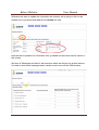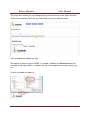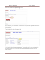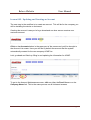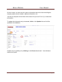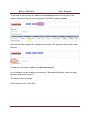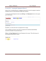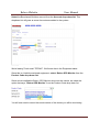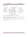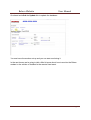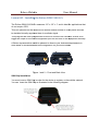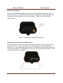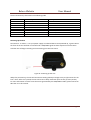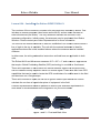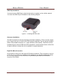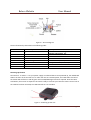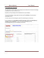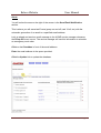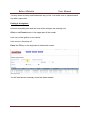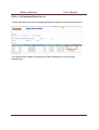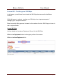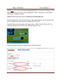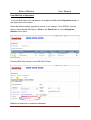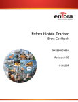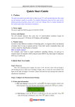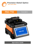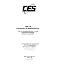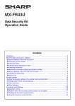
1
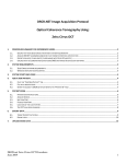
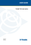
2011
Bolero Website
User Manual
Bolero Wireless
www.bolerowireless.com
4/29/2011
Bolero Website
User Manual
Document Title: User Manual: Bolero Website
Version: 1.05
Date: 5/9/2011
Status: Release
Document Control ID: GSM2000PB002MAN
General
All efforts have been made to ensure the accuracy of material provided in this document
at the time of release. However, the items described in this document are subject to
continuous development and improvement. All specifications are subject to change
without notice and do not represent a commitment on the part of Bolero Wireless
(herein called Bolero). Bolero will not be responsible for any loss or damages incurred
related to the use of information contained in this document.
The Bolero Modem is not intended for use in life support appliances, devices or systems
where a malfunction of the product can reasonably be expected to result in personal
injury. Bolero customers using, integrating, and/or selling the Bolero Modem for use in
such applications do so at their own risk and agree to fully indemnify Bolero Wireless for
any damages resulting from illegal use or resale.
Copyright
Complying with all applicable copyright laws is the responsibility of the user. Without
limiting the rights under copyright, no part of this document may be reproduced, stored
in or introduced into a retrieval system, or transmitted in any form or by any means
(electronic, mechanical, photocopying, recording or otherwise), or for any purpose,
without the express written permission of Bolero Wireless.
Bolero may have patents, patent applications, trademarks, copyrights or other
intellectual property rights covering subject matter in this document. Except as
expressly provided in any written license agreement from Bolero, the furnishing of this
document does not give you any license to these patents, trademarks, copyrights or
other intellectual property.
©2011, Bolero Wireless. All rights reserved.
BOL2000BP002MAN
V 1.05
Page 2
Bolero Website
User Manual
Contents
Introduction ............................................................................................................................................ 4
Lesson 001 - How To Create A Wireless Account...................................................................................... 5
Lesson 002 - Modifying Subscriber Preferences ....................................................................................... 9
Lesson 003 - Updating and Creating an Account .................................................................................... 15
Lesson 004 - Creating the Equipment Record ......................................................................................... 19
Lesson 005 – Installing the Enfora GSM1318 SA-G+ ............................................................................... 23
Lesson 006 – Installing the Enfora GSM2354 Mt-Gi................................................................................ 27
Lesson 007 - Generating and Viewing Events ......................................................................................... 33
Lesson 008 – Customizing the User Interface ......................................................................................... 40
Lesson 009 – Tracking your SIM Chips.................................................................................................... 49
BOL2000BP002MAN
V 1.05
Page 3
Bolero Website
User Manual
Introduction
This guide will walk you through the various steps you will use to set up and start using
your Wireless modem. This guide includes all the steps from creating the Bolero
Account up to an including customizing the Bolero User interface to align with your
business requirements.
In a nutshell, what Bolero offers you is the hardware, the network and the backend
website that you can use for your own business to manage the various pieces of
equipment that you have out in the field.
With the Bolero Wireless system, you can easily automate this function and the
software can email your service department when an action needs to take place.
In this document, an item in Bold text will usually identify an action to be taken by the
user.
BOL2000BP002MAN
V 1.05
Page 4
Bolero Website
User Manual
Lesson 001 - How To Create A Wireless Account
Click on the Signup/Demo link up in the top right corner of the Bolero home page and
you will be redirected to the Signup page.
In this page you will need to provide the following information including your
• Company Name
• Email Address
• Login Name
• and Password
BOL2000BP002MAN
V 1.05
Page 5
Bolero Website
User Manual
In this demonstration, we are going to sign up a company called ACME.
A valid e-mail address must be entered so you can get notifications and things of that
nature.
Your login name must be unique. We recommend you use your first initial and last
name, but anything can be used as long as someone else has not already used it.
Finally pick a password, verify it, and click on the Create User Button.
After this, a message will be shown saying your account was successfully created.
The login link can be found in the upper right hand corner, so go ahead and click the
Login link.
BOL2000BP002MAN
V 1.05
Page 6
Bolero Website
User Manual
You will be redirected to the login page.
Go ahead and enter your user name and password then click on the Submit button.
This is the process that you’ll do from now on to sign into the account.
When you first login, you will be redirected to the Account List screen
Let’s have a quick overview of what you’re seeing here.
By default, an account was created in the Bolero Portal for your business. We will
update this information later on in future lessons.
In the top right hand corner you will see the
• a Preferences link;
• a Help link;
• and a logout link.
BOL2000BP002MAN
V 1.05
Page 7
Bolero Website
User Manual
The Help link contains all the videos you can use to learn about how to setup your
equipment and use the Bolero Web Portal.
These videos contain the same information contained in this User Manual.
You will notice the first video link is the lesson you are reviewing now.
The lessons in this manual are sequential and should take you no longer than1 hour to
complete and to start using the Bolero portal.
That’s it for now. In the next lesson, we will learn how to customize the website for your
own business.
BOL2000BP002MAN
V 1.05
Page 8
Bolero Website
User Manual
Lesson 002 - Modifying Subscriber Preferences
Now that we’ve gone ahead and created our Bolero Account, let's go ahead and
customize it to your business.
You will only need to do this once and once it has been set, it will be remembered for
future sessions.
To customize your account, click on the Preferences link in the upper right hand
corner.
Once clicked, you will be brought to the Subscriber Preferences screen
Basic information can be stored here including the
Company Name
The desired startup screen
Your time zone
Province/State
Country
Zip Code
Phone Area Code
Let's change the default state to Massachusetts, USA along with our zip code and our
phone area code. This will be used later on when creating new customer accounts.
BOL2000BP002MAN
V 1.05
Page 9
Bolero Website
User Manual
Whenever we want to update the information we entered, we’re going to click on the
Update link so go ahead and click on the Update link now.
Now that we've updated our information let’s go ahead and see what else we can do in
this screen.
We have a "Messages and Alerts" tab area here which we will get into at later lessons.
It's used to send email messages when certain events occur on the GSM modem.
BOL2000BP002MAN
V 1.05
Page 10
Bolero Website
User Manual
We have the "Customer Labels" tab here so you can customize certain labels to what
your business does. Maybe in your business you are tracking volume levels so you
would want to change the default labels here.
We will get into this in a later on lesson.
BOL2000BP002MAN
V 1.05
Page 11
Bolero Website
User Manual
The Logo tab is where you can change the logo that shows up in the upper left hand
corner of the interface. With this you can brand your site to what you want.
Let’s go ahead and update our logo.
We happen to have a logo for ACME. To upload it, click on the Browse button and
navigate to the logo location. It needs to be one of the standard logo types, jpeg, png ,
etc
So let's go ahead and select it.
BOL2000BP002MAN
V 1.05
Page 12
Bolero Website
User Manual
When done, click on the Upload Logo button.
Once uploaded, you’ll see that the Acme logo has changed in the upper left hand corner
of the interface.
The final tab is the User Information tab.
You'll use this tab to change your password. You can also add in your secret question
and secret answer if you would like to help remember what your password is if you
forget it later on.
BOL2000BP002MAN
V 1.05
Page 13
Bolero Website
User Manual
That’s about it for now on Preferences. Let's click back to our Help section to get ready
for the next Lesson.
When you are done, remember to click on the Logout link.
BOL2000BP002MAN
V 1.05
Page 14
Bolero Website
User Manual
Lesson 003 - Updating and Creating an Account
The next step in the workflow is to create an account. This will be for the company you
will be installing the device or devices at.
Creating the account is easy so let’s go ahead and see how we can create a user
customer account.
Click on the Accounts button in the upper part of the screen and you’ll be brought to
the Account List screen. Here you will see by default the account that the system
automatically created for the new company ACME Inc.
Let’s go ahead and finish up filling in and updating the information for ACME.
To get to the Account Maintenance screen, click on either the Pencil icon or on the
Company Name link. This is the same process on all list based screens.
BOL2000BP002MAN
V 1.05
Page 15
Bolero Website
User Manual
On this screen, you can enter the various information about the client including the
company name, phone number, address information, etc.
We will not complete all the fields in this lesson but you can fill it in if you have that
information.
To update the information we just entered, click on the Update link and it will be
updated in the database.
Another way of updating is by clicking on the Green check mark. Use whichever
method you prefer.
BOL2000BP002MAN
V 1.05
Page 16
Bolero Website
User Manual
To go back to the Account list, click on the Accounts button in the top part of the
screen. Notice that the account information for ACME has been updated.
Now that we have updated our company information, let's go ahead and create a new
account….
To add the new account, click on the New Account link.
In our example, we are creating an account for "Benchmark Builders" whom we have
leased a large dump truck to.
The contact name is Susan.
Phone number is 617-343-3419
BOL2000BP002MAN
V 1.05
Page 17
Bolero Website
User Manual
Once you have finished, click on the Update link.
You will notice that the new Account will be created and a new Account Number will be
generated for this customer.
That is it for this lesson.
In the next lesson we’re going to go ahead and enter the equipment for this new
customer that we’re going to use to monitor.
BOL2000BP002MAN
V 1.05
Page 18
Bolero Website
User Manual
Lesson 004 - Creating the Equipment Record
Lesson four is a similar process to creating an account but now we’re going to create an
Equipment record for the equipment ACME will be leasing.
You can get to the Equipment screen by clicking on the Equipment button in the upper
part of the screen,
By default, you will notice that our equipment list is empty.
Let's go ahead and create a new piece of equipment for the Benchmark Builders
Account we created in the previous lesson.
Click on the New Equipment link in the Equipment List screen. This will bring you to
the Equipment Maintenance screen.
BOL2000BP002MAN
V 1.05
Page 19
Bolero Website
User Manual
Select the Benchmark Builders account from the Account drop-down list. This
dropdown list will grow as more Accounts are added to the system.
We're leasing Truck serial "DT2342". We'll enter that in the Equipment name.
Since this is a Vehicle monitored equipment, select Bolero GPS Monitor from the
Product Code drop-down list.
Since we’ve installed the Bolero GPS Monitor device on the vehicle, we select the
option that says, "Bolero GPS Monitor" from the Product Code drop down list.
You will now need to record the serial number of the device you will be monitoring.
BOL2000BP002MAN
V 1.05
Page 20
Bolero Website
User Manual
Your device was shipped with a sticker on the back of that looks like what is shown in
the following image.
Enter the code found after the SRN: code usually 13-16 digits long.
Please double check that number as it must to be exact. If an incorrect value is entered,
the system will not be able to track the device for you.
You'll notice a SIM Chip number value can be entered. We will talk about managing SIM
Chips in a future lesson.
BOL2000BP002MAN
V 1.05
Page 21
Bolero Website
User Manual
Go ahead and click the Update link to update the database.
You now have the modem set up and you can start monitoring it.
In the next lesson we’re going to talk a little bit more about how to monitor the Bolero
modem in the vehicle or installed in the remote fixed asset.
BOL2000BP002MAN
V 1.05
Page 22
Bolero Website
User Manual
Lesson 005 – Installing the Enfora GSM1318 SA-G+
The Enfora GSM1318 SAG+ measures 2.5" x 2.5" x 1" and is ideal for applications that
do not require GPS.
This unit operates on the GSM/GPRS cellular network similar to a cell phone and can
be installed virtually anywhere there is a cellular signal.
This program has been programmed to allow for counts to be recorded, as well as to
trigger an output on the remote equipment (turn on and turn off the equipment remotely
A Bolero representative would be pleased to discuss your business requirements in
more detail to recommend the best configuration for your environment.
.
Figure 1 and
an 2 – Front and Back View
SIM Chip Installation
You must insert a SIM Chip in order for the device to register on the cellular network.
You can Insert the SIM Chip as illustrated in the following diagram.
Figure 3 – Inserting the SIM Card
BOL2000BP002MAN
V 1.05
Page 23
Bolero Website
User Manual
Antennae Installation
Connect the antennae supplied with unit on the female antennae connector found on
the front of the unit to the right of the SIM Card slot. Additional of different lengths and
strength may be purchased to suit your requirement. Please contact your Bolero
representative.
Figure 4 - Installing the GSM/GPRS Antennae
Eight Pin Molex Connector and RS232 Port
On the left side of the unit is the eight (8) Pin Molex connector. This connector is used
to power the unit, as well as to interface to the equipment you will be installing the
device on. You may create your own connector or purchase a pre-made wire and molex
connector from Bolero. The RS232 can be found on the right hand side of the unit. It will
not be required for your installation.
Figure 5 – Eight Pin Molex and RS232 Connectors
BOL2000BP002MAN
V 1.05
Page 24
Bolero Website
User Manual
You can make your own cable if required. The following is a list of the parts you would need to make
your own cable:
Figure 6 – Molex Connector Part List
Eight Pin Wiring Diagram
Installing the GSM/GPRS modem in a piece of equipment is a three to four wire installation depending
on what your business requirements are. The unit must be connected to a constant power from 6V up
to an including 40V. The following diagram is the pin out diagram for the unit.
Figure 7 – Pin Out Diagram
BOL2000BP002MAN
V 1.05
Page 25
Bolero Website
User Manual
The Pin functionally is described in the following table
Pin Number
Pin – 1
Pin – 2
Pin – 3
Pin – 4
Pin – 5
Pin – 6
Pin – 7
Pin – 8
Functionality
Not used
Not used
Not used
Ground
Supply Voltage
Counter
Output
Not used
Description
Black Wire.
Red Wire. (6 – 40V)
(3.3 – 40V)
(3.3 – 40V)
Powering Up the Unit
Connect Pins - 4 and Pin – 5 to your power supply as indicated above. Once powered up, a green LED on
the front of the unit will flash on and off until a GSM/GPRS signal has been acquired. Once the LED is
solid the unit will begin recording and transmitting your business events.
Figure 8 – Powering up the Unit
When first powered on, the unit will commence sending wakeup messages every six (6) minutes for the
first ½ hour. After the ½ period, the unit will revert to daily mode and report in two (2) times per day.
For more information on how to see the events generated by the GSM/GPRS modem, please see lesson
007 later on in this manual.
BOL2000BP002MAN
V 1.05
Page 26
Bolero Website
User Manual
Lesson 006 – Installing the Enfora GSM2354 Mt
Mt-Gi
Two versions of the Enfora GPS modem exist that have been certified by Bolero.
Bolero One
includes an internal antennae (also known as the Mt-Gi) and the other includes an
external antennae (the Mt-Gu)
Gu). The only difference between the two units is the
antennae configuration. In both cases, the antennae may be purchased from Bolero
Wireless. Please contact your Sales Representative for more information.
The unit with the internal antennae is ideal for ins
installation in an outdoor vehicle where a
line of sight to the sky is available. The unit with the external antennae is ideal for
applications where the unit is installed indoors where the antennae can be installed
outdoors.
In either case, the
he wiring schematics
schematics instructions outlined here are applicable to both
units.
The Enfora Mt-Gi and Mt-Gi
Gi both measures 2.5" x 2.5" x 1" and is ideal for applications
that require Global Positioning Satellite ((GPS)) technology in a mobile or fixed asset.
asset
These units operates on the GSM/GPRS cellular network similar to a cell phone and
can be installed virtually anywhere there is a cellular signal.
signal These units
unit also have GPS
capabilities
ies that can be used to locate the GPS coordinates of a mobile asset in the field
and be shown on a Google maps.
These units includes 2 inputs, as well as an ignition sense input that can be used to
calculate the run-time
time of a particular piece of equipment in the field.
A Bolero representative would be pleased to discuss your business requirements in
more detail to recommend the best configuration for your environment.
.
Figure 1 and
an 2 – Front and Back View
BOL2000BP002MAN
V 1.05
Page 27
Bolero Website
User Manual
SIM Chip Installation
You must insert a SIM Chip in order for the device to register on the cellular network.
You insert the SIM Chip as illustrated in the following diagram.
Figure 3 – Inserting the SIM Card
Antennae Installation
The Mt-Gi includes an internal antennae to facilitate installation. There must be a direct
line of sight to the sky in order for the GPS signal to acquired. The unit can be installed
within a non-metallic container (i.e., under the dash of the vehicle). The Mt-Gu can be
installed with an external GSM and GPS antennae for install location where a direct line
of sight is difficult or where the unit is installed in a metal enclosure.
Eight Pin Molex Connector
On the back of each unit is the eight (8) Pin Molex connector. This connector is used to
power the unit, as well as to interface to the equipment you will be installing the device
on. You may create your own connector or purchase a pre-made wire and Molex
connector from Bolero.
BOL2000BP002MAN
V 1.05
Page 28
Bolero Website
User Manual
Figure 4 – Eight Pin Molex Connector
You can purchase a pre-made 3 or 6 foot wire with the Molex connector already installed or you can
make your own cable if required. The following is a list of the parts you would need to make your own
cable:
Figure 5 – Molex Connector Part List
Eight Pin Wiring Diagram
Installing the GSM/GPRS modem in a piece of equipment is a two to five wire installation depending on
what your business requirements are. The unit must be connected to a constant power from 7V up to
and including 40V. The following diagram is the pin out diagram for the unit.
BOL2000BP002MAN
V 1.05
Page 29
Bolero Website
User Manual
Figure 6 – Pin Out Diagram
The Pin functionally is described in the following table:
Pin Number
Pin – 1
Functionality
Ignition
Description
White wire. Tied to the ignition of the
vehicle, pump power, etc.
Pin – 2
Pin – 3
Pin – 4
Pin – 5
Pin – 6
Pin – 7
Pin – 8
Not used
Not used
Ground
Supply Voltage
Input 1
Input 2
Not used
Red wire. IO1. (7– 40V)
Orange wire. IO2. (3.3 – 40V)
Blue wire. Switched to Ground
Powering Up the Unit
Connect Pins - 4 and Pin – 5 to your power supply as indicated above. Once powered up, the middle Red
LED on the front of the unit will turn on. After the unit has received power, the USR1 LED to the left of
the Power LED will flash on and off green until a GSM/GPRS signal has been acquired. Once the LED is
solid Green, the unit will as acquired a lock and is ready to transmit your business events. Once a lock on
the satellite has been achieved, the USR2 LED will turn to solid blue.
Figure 7 – Powering up the Unit
BOL2000BP002MAN
V 1.05
Page 30
Bolero Website
User Manual
GPS/GSM/GPRS Mt-Gu with External Antennae
The Enfora Mt-Gu is the same in terms of functionality as the Mt
Mt-Gi,
Gi, but includes the ability to install a
GSM and GPS external antennae
antennae.. You will use this GPS/GSM/GPRS modem when you are finding it
difficult to acquire or lock on to a GPS or cellular signal or where the unit must be installed
in
in a metal
enclosure.. The Power up process remains the same. The middle LED will light Red when powered up, the
left LED will flash green when acquiring a GSM ssignal,
ignal, and will turn solid when a signal has been
acquired. Finally, the LED on the right will turn Red once a lock on the satellite is acquired.
Figure 8 – Enfora Mt-Gu
This unit includes two external antennas. These antennas can be purchased from Bolero
Boler Wireless if
necessary. The antennae
nnae on the left with the blue connector is the GPS antennae while the antennae on
the right with the purple connector is the GSM antennae.
BOL2000BP002MAN
V 1.05
Page 31
Bolero Website
User Manual
Setting Up for Lesson 007
Lesson 007 assumes that you are using either the Mt-GI or the Mt-Gu GPS/GSM/GPRS Modem, that it
has been powered up and that that Pin – 1, the ignition, has been wired to a switch that can send 12V.
With this setup, you will be able to follow along with the lesson.
The complete wiring diagram for this modem is depicted in the following diagram.
Figure 9 – Enfora GPS Wiring Diagram
If you are using the SA-G+ unit (counter unit), the lesson will remain largely the same, but the events
generated by the unit will be different.
BOL2000BP002MAN
V 1.05
Page 32
Bolero Website
User Manual
Lesson 007 - Generating and Viewing Events
In this Lesson, you will learn how to generate and view events in the Bolero portal.
Once a Bolero device has been installed in the field, it will begin to transmit events
when various events occur.
In the case of the Bolero GPS Monitor, events can be triggered when the ignition is
turned on and off or when inputs 1 or 2 are triggered.
In the case of the Bolero Cycle Manager, the counter is transmitted to the back end
every 12 hours or when other events occur.
In both cases, all messages can be displayed in the Events section of the portal.
Click on the Events button in the upper section of the screen. You will notice that no
events are displayed. This is normal.
We will trigger some events in the Web portal now
(Please note: In this lesson, we will be demonstrating the Bolero GPS Monitor modem.
It has been wired to a simple rocker switch).
Let's go ahead and turn on the ignition on this device.
BOL2000BP002MAN
V 1.05
Page 33
Bolero Website
User Manual
In order to see the "Ignition On" message we just triggered, we need to refresh our web
page.
Press the F5 key on your keyboard or select the option to refresh your browser to
refresh the page.
You will notice that a new record is displayed documenting the date/time the ignition
was activated on this particular piece of equipment.
Every piece of equipment you monitor using Bolero devices will show up here.
Let's go ahead and turn the ignition off on the device.
Now, press the F5 key again and you'll see the message updated with the date/time the
equipment was turned off.
BOL2000BP002MAN
V 1.05
Page 34
Bolero Website
User Manual
If you do not see the message updated, press the F5 key again until the message has
been updated.
For GPS signals, it typically takes a few minutes for a lock to occur on the satellites
depending on how clear it is and how good the line of sight is to the sky.
If there was a GPS signal acquired, the GPS Column would show the value Yes. In our
session the GPS column is set to No meaning it did not get a lock on a satellite. We will
talk about this later on in the lesson.
Triggering inputs on Pins 6 and 7 on the Bolero GPS Monitor will also generate events
in the user interface. These events could be tied to real life events like a float switch
activating, or a pressure switch activating.
To view the individual events that occurred, click on the Equipment Event List Link.
This screen lists all the individual event s that occurred in the last 7 days.
In our case, the ignition came on, the unit woke up and ignition was turned off.
The date and time of each event will be listed here as well.
All the individual events generated in the system will be shown in the Equipment Event
List.
The summary of all ignition on/off and a summary of the input 1 and 2 events will be
shown in the Equipment Summary List
BOL2000BP002MAN
V 1.05
Page 35
Bolero Website
User Manual
To see some GPS events, let us log into the demo account.
Click on the Logout link…
Then click on the Login link…
Sign on as username: demo with a password of demo.
Click the Submit button.
BOL2000BP002MAN
V 1.05
Page 36
Bolero Website
User Manual
As you can see we’ve been testing various units here at Bolero, there are many events
that have gone on.
This is a good time to show you how to navigate pages within a grid view.
If you want to go back in time, click on the 2 link at the bottom of the screen for the next
page of events in the data base.
Alternatively, you can click on 3 link to get to the very first record for this device in this
example.
BOL2000BP002MAN
V 1.05
Page 37
Bolero Website
User Manual
Let's go back to page 1 by clicking on the 1 link
Let’s have a look at a GPS event.
You’ll see here that the GPS column has a Yes.
You will notice that the Map icon is only activated when the GPS column contains the
value Yes. This means that a GPS Lock was acquired while the equipment was on and
the ignition was turned off.
Go ahead and click on the Map icon.
A new screen is displayed showing us where the device was at that time.
BOL2000BP002MAN
V 1.05
Page 38
Bolero Website
User Manual
The interface uses Google maps, so we can drill down into the map area by double
clicking on the map.
Click on the Satellite button in the upper left hand corner to switch to the to the satellite
view.
That ends our lesson on how to generate and view events.
You should now be able to easily view and analyze the business events generated by
the Bolero solution.
BOL2000BP002MAN
V 1.05
Page 39
Bolero Website
User Manual
Lesson 008 – Customizing the User Interface
In this lesson we will learn how to customize the Bolero User Interface.
Customizing the interface is an optional step and is not required.
Customizing the user interface will tailor fit it to your business operation.
Startup Screen
You will notice that when you log into the portal, that the system will immediately bring
you to the Account List page.
This option can be customized in the Preferences screen.
Click on the Preferences link and in this page you can choose the startup screen you
wish to display whenever you log in.
You can see that the following screens are available in the Startup Screen drop down
list.
BOL2000BP002MAN
V 1.05
Page 40
Bolero Website
User Manual
For this application, we would prefer that the Equipment Summary List screen is shown
by default.
Click on the Startup Screen drop-down list and select the Equipment Summary
screen.
Click on the Update link to update the database.
Now every time you log in, the system will bring you to this screen
Go ahead and log out and log back in to see this in action.
You will see that we are now by default in the Equipment Summary List screen.
Labels
We can further customize the interface by changing the default labels shown in this grid.
These labels can be given different values.
Perhaps you are using this website to monitor a pump and a tank monitoring solution.
Instead of Equipment On and Equipment Off, we want it to read Pump On and Pump
Off.
Another change we would like to make is to change the input labels to ½ Full and ¾ full.
BOL2000BP002MAN
V 1.05
Page 41
Bolero Website
User Manual
To customize these labels, click on the Preferences Link, then click on the Custom
Labels tab.
This is the screen where you can customize the labels.
You will see on the left hand side the default label provided.
Let's go ahead and change them to the new values.
Change Equipment On and Off to Pump On and Off
Change Input 1 to ½ full
Change Input 2 to ¾ full
Click the Update link then click on the Events button in the upper part of the screen to
go back to the Equipment Summary List screen
BOL2000BP002MAN
V 1.05
Page 42
Bolero Website
User Manual
You will notice that the screen is now displaying the data with the new labels.
Customizing Messages
We can customize the messages displayed in the Equipment Event List screen to what
we want them to read as.
In our application, we want the messages to say Pump On, Pump Off, ½ full and ¾ full.
BOL2000BP002MAN
V 1.05
Page 43
Bolero Website
User Manual
To change the default messages displayed, click on the Preferences Link and then
click on the Messages and Alerts tab.
Go ahead and change the Vehicle Ignition On and Off to Pump On and Off
Change the Input 1 message to Tank ½ full
Change the Input 2 message to Tank ¾ full
Click the Update link to update the database
Now, whenever one of these messages are generated, they will be generated with the
new message value.
BOL2000BP002MAN
V 1.05
Page 44
Bolero Website
User Manual
Limiting Messages Displayed
The checkmark in front of each event message option determines whether the message
is displayed in the user interface or not.
By default, all the messages will be displayed in the user interface.
To turn off a message, simply undo the check mark by clicking on the associated
checkmark control.
You can easily turn the message on and off by reselecting the check mark.
Let's go ahead and turn the Wakeup and OK messages off for our application by
clicking on the checkmarks in front of the Wakeup Message and OK
(Acknowledgement) option as illustrated in the screen.
BOL2000BP002MAN
V 1.05
Page 45
Bolero Website
User Manual
Alerts
You will notice the area on the right of the screen is the Send Email Notification
section.
This is where you will associate Events (pump on and off, tank ¾ full, etc) with the
automatic generation of an email to a specified email address.
Let's go ahead and send an email message to the ACME service manager whenever
the Pump Off event occurs. The service manager will use this information to schedule
an emergency work order.
Click on the Checkbox in front of the email address.
Enter the email address in the space provided.
Click the Update link to update the database.
BOL2000BP002MAN
V 1.05
Page 46
Bolero Website
User Manual
You may enter as many email addresses as you like. Just make sure to separate each
one with a semicolon.
Putting it all together.
Lets test everything now and see how all the changes are working now.
Click on the Events button in the upper part of the screen
Let's turn on the ignition on our device
Let's now turn the pump off.
Press the F5 key on the keyboard to refresh the screen.
You will see the new summary event has been created.
BOL2000BP002MAN
V 1.05
Page 47
Bolero Website
User Manual
Click on the Equipment Event List link.
You will see that all the new messages generated include the new message values.
You should now be able to customize the user interface to fit your business
requirements.
BOL2000BP002MAN
V 1.05
Page 48
Bolero Website
User Manual
Lesson 009 – Tracking your SIM Chips
In this lesson, you will learn how to track the SIM Chips that are used in the Bolero
modems.
While this lesson is optional, tracking your SIM chips is an important aspect of
managing your equipment network.
Bolero's monthly billing process is based on the number of active SIM Chips you have in
use in a given month.
Create SIM Chip
Let's go ahead and create an Equipment Record for the SIM Chip
Click on the Equipment button in the upper portion of the screen
Click on the New Equipment Link.
BOL2000BP002MAN
V 1.05
Page 49
Bolero Website
User Manual
Select Your Account from the Account drop-down list. We recommend keeping all the
SIM Chips in one account for easier management. Later in the lesson, you will link the
SIM Chip to the Bolero modem.
Select the SIM Chip option from the Product Code drop-down list.
Name the Equipment. This is the short name. We recommend you use the first four and
last four digits of the SIM Chip ID (for example SC8901-3343).
The SIM Chip number is typically a 20 digit number. 8901 4104 2335 5743 232. The
SIM Chip number can be found on the SIM chip shipped to you.
Enter the complete SIM Chip number into the SIM Chip ID field.
BOL2000BP002MAN
V 1.05
Page 50
Bolero Website
User Manual
Click on the Update Link
BOL2000BP002MAN
V 1.05
Page 51
Bolero Website
User Manual
Link SIM Chip to Equipment
To link the SIM Chip to the equipment it is installed in click on the Equipment button in
the Upper part of the screen
Select the Bolero modem equipment record, in our example, Truck DT2342, that we
want to associate the SIM Chip to. Click on the Pencil icon or on the Equipment
Number link to edit it.
Enter the SIM Chip number in the SIM Chip ID field.
Click the Update link to update the database.
BOL2000BP002MAN
V 1.05
Page 52
Bolero Website
User Manual
It is recommended that process be performed on each installation of each modem in the
field.
You should now be able to manage the SIM Chips in your operation.
BOL2000BP002MAN
V 1.05
Page 53