1
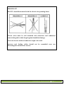
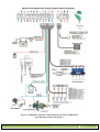
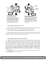
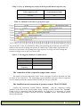
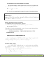
TECHNOLOGYGAS.,CO.LTD http: www.technologygas.com e-mail: [email protected] mobile: +6685-2555835 Assembly Instructions of gas injection control systems VERONA January 2010, Lublin IMPORTANT! The manufacturer does not bear any responsibility for using the device not in accordance with the service manual. The service manual is an integral part of a device and is handed on to its users. It is forbidden to introduce any changes to VERONA which may result in losing guarantee rights. Opening of the controller casing or damage of the lead guarantee seal will result in the loss of guarantee rights. IMPORTANT! The controller should be mounted: - AWAY from possible WATER INFILTRATION, - AWAY from EXCESSIVE HEAT SOURCES, - AWAY from IGNITION WIRE, - Perform good electrical connection, - After removing the fuse system enters the gasoline supply, - Do not open during operation of the system. Assembly Instruction Page 2 IMPORTANT! The ECU should be mounted with the electric wire pointing down. Electric wires must be well insulated and connectors and conductors secured along their whole length against insulation damage. First-rate electric soldered connectors ought to be used. Injectors and feeding cables should not be assembled near any electromagnetic interference sources. Assembly Instruction Page 3 LIST OF CONTENTS 1. TECHNICAL DATA ...............................................................................................................5 2. SYSTEM OPERATION AND INSTALLATION . .................................................................6 General purpose of the system . ...............................................................................................6 INSTALLATION SCHEMA. .................................................................................................6 3. Installing of the VERONA system........................................................................................... 8 The installation of the gas reducer .......................................................................................... 8 The installation of the controller in the engine chamber . ...................................................... 8 The connection of the rotational speed signal RPM ............................................................... 8 The connection of oxygen sensor’s signal (lambda probe) . ................................................... 8 The connection of the tank’s gas level sensor . ....................................................................... 9 The connection of gas electro valves . ................................................................................... 10 The installation of a gaseous phase filter with a distributor. ................................................. 10 The installation and connection of injectors. ......................................................................... 10 The connection of the evaporator temperature sensor . ......................................................... 11 The installation and connection of pressure sensor MAP SENSOR . .................................11 The installation and connection of the central unit ............................................................... 12 Power supply connection . .................................................................................................... 12 The installation of fuses . ...................................................................................................... 12 3. THE PROGRAMMING AND CONFIGURATION OF THE CONTROLLER . ................ 12 A description of the calibration program ............................................................................. 12 The Main Menu window ...................................................................................................... 12 In the Configuration window . ........................................................................................... 14 The emergency password . .................................................................................................... 18 4. CALIBRATION OF THE VERONA SYSTEM ................................................................... 19 Auto calibration .................................................................................................................... 19 Correction Map .................................................................................................................... 22 Assembly Instruction Page 4 1. TECHNICAL DATA Table 1.1. Technical data of gas injection control system LPG/CNG VERONA Description Value 12 V Nominal supply voltage Admissible supply voltage range 10 16 V Maximum value of current consumption 7A Minimum value of velocity signal voltage 3V Admissible range of ambient temperature –40 C to +120 C Protection degree IP66 Table 1.2. Description of additional equipment: Description Value Type of engine Petrol spark- ignition combustion engine Types of the petrol injection - simultaneous multi-point - MPI (Multi-Point Injection) - sequential– SFI (Sequential Fuel Injection) - semi sequential from 700 cm3 from 1 to 4 (or 1 to 8) optional from 5 kW Capacity Number of cylinders Cylinder layout Power Manufactures Advice Servicing the system and all check have to be made according the conditions written in the guaranty book. ECU’s firmware actualisation The newest firmware versions for the ECU are available on the web page of the manufacturer: Assembly Instruction Page 5 2. SYSTEM OPERATION AND INSTALLATION General purpose of the system The gas injection system control VERONA is an electronic control device which is designed to control the fuel-air mixture ratio in a car spark ignition engine provided with one or two lambda sensors. LPG or CNG gas is its fuel. INSTALLATION SCHEMA Installation schema for the VERONA system Assembly Instruction Page 6 Fig.2.1. A diagram of electric connections for the LPG VERONA II gas injection system (4 injectors) Assembly Instruction Page 7 3. Installing of the VERONA system The installation of the gas reducer Install the gas reducer using two sheet plates. Mount the gas reducer and the gas valve in the engine compartment in a location far away from a direct heat source (the exhaust manifold). Select a location to mount the gas reducer which is optimal to connect the gas reducer with the engine cooling system. Drill holes and protect them against corrosion. Next, screw down the gas reducer using bolts included in the set. Connect the gas reducer to the cooling system using T-pipes and water conduits included in the set; secure them by clamp hoops. The installation of the controller in the engine chamber Install the controller far away from any sources of electromagnetic disturbances (e.g. an ignition coil), and from high temperature sources (e.g. the engine’s exhaust manifold), and at a safe distance from any tanks containing liquids (e.g. cooling fluid equalizing tank.) ATTENTION VERY IMPORANT: The controller should be always mounted with the sockets pointing down!!!!!!!!!!!!!!!!!!!!!!!!!!!!!!!!!!!!!!! The connection of the rotational speed signal RPM The RPM signal pin may by detected by a voltage tester or an oscilloscope. The frequency of the impulse transmitted to the petrol controller increases together with the engine rotational speed and so does the blinking frequency of the voltage tester and the frequency of the signal on the oscilloscope screen. It is advised to take the signal pin from the petrol computer. The voltage amplitude value of RPM signal within the 12V limit is defined as a STRONG signal whilst the one within 2.5V is defined as a WEAK signal. The RPM wire ought to be put far away from high voltage conductors and any electromagnetic interference sources. If the signal is lower than 2,5 V, an RPM amplifier must be additionally installed – available as an option. When you cannot find the RPM signal in new cars you have to try to connect to the petrol injector (-) and activate the function (60) like in the F6 window – admissible CUT OFF time to RPM on LPG. The connection of oxygen sensor’s signal (lambda probe) OPTION do not connect the lambda probe. Connect only when problems at calibration appear. Never connect the lambda probe by calibration with OBD – the signal is shown automatically. In order to connect the oxygen sensor with the gas controller, the probe’s signal wire needs to be found, cut and soldered to the controller’s wire lettered O2_IN (violet). Then the gas controller reads the voltage value from the lambda probe and wide range lambda sensor. Assembly Instruction Page 8 The connection of the tank’s gas level sensor Mount the sensor according to the drowning 2a or 2b, specially note the position of the electro valve connection. 1. Mount the sensor with two screws in such way that you still have the possibility to adjust it. 2. Connect according to the drawing 1 and connect the plug to the sensor 3. Start the engine and switch to LPG. 4. Connect with the diagnostic program. Select the hallotron sensor as the level indication sensor. The projecting filter will cause slow changes in the projection of the LG level doe to the quick changes of the sensor showings. This eliminates the blinking with the LPG level diodes of the switch during driving on a not equal road but makes the calibration of the sensor more difficult. That's why during the calibration you shouldn't switch of the filter. 5. Turning the sensor according to hand movement of opposite to them set the needed number of diodes on the switches display (on the screen of the computer in the visualisation window). 6. Mount the sensor. 7. If the hallotron sensor wasn't conjectural sensor save the ECU settings. 8. Disconnect the diagnostic joint from the computer. The projecting filter will be switched on automatically after turning on the ignition. black - ground green - signal red - (+12V) from electrovalve Fig.1. A view of the hallotron sensor Assembly Instruction Page 9 Hallotron sensor Hallotron sensor Electrical connector Electrical connector Float Float Fig. 2a Right Lovato valve The turning of the sensor clockwise results in the reduction of the quantity of diodes displayed on the panel, while the turning of the sensor anticlockwise results in the increase of the quantity of diodes displayed on the panel. Fig. 2b Left Lovato valve The turning of the sensor clockwise results in the increase of the quantity of diodes displayed on the panel, while the turning of the sensor anticlockwise results in the reduction of the quantity of diodes displayed on the panel The connection of gas electro valves The gas electro-valves installed at the gas tank (the multi valve) and near the gas reducer/ evaporator should be connected to the gas controller wire lettered E_LPG (blue ) The installation of a gaseous phase filter with a distributor The gaseous phase filter is to be installed between the evaporator and the gas injectors according to the flow direction marked on the casing, using pressure rubber conduits. The connectors ought to be protected with metal band clamps. The installation and connection of injectors Install the injectors in the vicinity of the suction manifold and locate it as far as possible from high-voltage conduits. Drill holes and screw down brazen ferrules (diameter 4mm) at the ends of supply manifold, near the engine’s inlet valves, so the gas will flow through them. Decline the main axes of the ferrules in the direction of the throttling valve and make an acute angle of about 75 ° against the collector. Connect the pipes with the ferrules of the injector electro valves using rubber pressure conduits (see Table 3.2). The connectors ought to be protected with metal band clamps. The length of the rubber conduits which connect injectors with supply manifold should be as short as possible. Connect the harness of supply and control conduits of the gas controller terminated in a 6-conduit plug with the injectors. In the outlet of the injector you have to mount a nozzle, which will adjust the gas flow to the engines demand. For choosing the nozzle use table below. Assembly Instruction Page 10 Table 2.1. Way of mounting the nozzles in the Pegas and Matrix injection rail: Cubic capacity [cm3] Nozzle diameter [mm] to 1600 1600 – over and turbo 2,1 4,0 Table 2.2. Method of selection of gas injectors type: The given table is only for information. When after mounting the nozzles the car works not stable on idle one has to change the nozzles for smaller ones. When under big load the car switches over to petrol ( the opening time of gas injectors is to big) one has to change the nozzles for bigger ones or don’t use them at all. Table 2.3. The suggested diameter of rubber hoses. Location Reducer - dispenser Dispenser - Injector Injector - manifold MAP sensor dispenser Inner diameter [mm] Ø 13 Ø8 Ø5 Ø4 The connection of the evaporator temperature sensor The signal of the gas temperature sensor in the evaporator is used to determine the time of petrol to gas switch-over. The temperature sensor installed in the gas reducer/evaporator is to be connected with the conduit marked TEMP_R of the gas controller. The installation and connection of pressure sensor MAP SENSOR Connect the connection conduit marked “Pressure” with the connection conduit installed in the filter of the gaseous phase using a rubber pressure conduit. The ‘Vacuum” ferrule must be connected with the atmospheric air. However, it is necessary to mount a rubber conduit with a length of around 5cm on the “Vacuum” ferrule. That conduit must be directed downwards. Assembly Instruction Page 11 The installation and connection of the central unit The central unit should be installed inside a vehicle, at an easily accessible location and should be visible from the driver’s seat. After the control unit is mounted, the harness of wires should be connected with a four-conductor square-cross section plug. Power supply connection For safety, the power supply should be connected at the end of all installation activities. IMPORTANT! Inspect all electrical connections for any breakdowns (electrical insulation) before power supply is connected. Next, the following devices need to be connected: -the GND (black) cable to the battery negative terminal (-). -the +12V controller supplying cable (red) with the battery positive terminal (+) The installation of fuses Finally, the car’s flat-fuses are installed in the sockets of the power supply cables and electric valves (in accordance with the assembly diagram). 4. THE PROGRAMMING AND CONFIGURATION OF THE CONTROLLER A description of the calibration program After starting the program, the Main Menu window appears. Program operation can be carried out using the keyboard or the computer mouse. After pressing a function button or clicking on the right screen key button, a sub-window is displayed. The Main Menu window In the “MAIN MENU” window there are keys used to navigate between different sub-windows of the program: CONFIGURATION, CALIBRATION, VISUALISATION, DIAGNOSTIC. On the bottom of the screen is the DATA EXHANGE button which allows: Saving the configuration to the file, Reading the configuration from the file, Preserving the configuration in the control unit Going back to the manufacturers settings Assembly Instruction Page 12 Drawing 3.1. OPTION window of the VERONA program ATTENTIN!!! TO prevent losing the controllers settings after lost of voltage you have to save them by pressing the “Store in the ECU” button and setting the ECU's password. The password has to contain 8 symbols and it will be needed by every attempt to connect with the ECU. Additional through the OPTIONS window it is possible to: connect through: selection of the port number through which the program will communicate with the control unit, chose the language in which everything is shown in the program, programming of the ECU it relays on transferring the program to the FLASH memory. This option is for loading new firmware to the LPG ECU. Assembly Instruction Page 13 Drawing 3.2. ECU Programming Window In the Configuration window -> Engine the type following be set: The of the can oxygen sensor (lambda probe) see page 15, The level of the rotational speed signal, RPM see page 15, The configuration of the rotational speed measurement - choose the number of, cylinder and coils to get the correct RPM reading, The type of injection system of the petrol engine see page 23, Engine’s cubic capacity, Turbo charging of the engine. NOTE! For a vehicle with a fuel semi sequential or simultaneous injection the signal of RPM rotational speed should be directly taken from the engine speed indicator. In this case the connection of the RPM conduit with the induction coil may result in incorrect operation of the gas supply system. Assembly Instruction Page 14 Fig. 3.3. Configuration Window In the CONFIGURATION window -> Injection system you can set: The type of fuel supply (LPG or CNG), The type of gas injection rail or injectors Valtek etc. The diameter of a nozzle installed in the injectors The type of gas reducer temperature sensor. Only if a different reducer the standard one was used you can change the factory settings The connection method of the gas pressure sensor MAP SENSOR in the gas reducer (to the supply manifold or to the atmosphere), The type of gas level sensor, see page 16 Whether the display filter is on or off – see page 17 In the window F3 CONFIGURATION -> Switching over it is possible to set the parameters of switching over from petrol/gas. The column on the left side shows the parameters that are responsible for switching over to petrol, and the column on right side is responsible for switching over to gas. When the system works correctly do not change the factory settings. The function allowed CUT OFF time to RPM –when in new cars you cannot find the RPM signal you have to connect to the petrol injector (-) and activate the function (60). Assembly Instruction Page 15 The Heating function - it is used for preheating of the injectors in winter conditions. There are 3 types of preheating: Weak, Medium and Strong depending from the climate zone. Fig. 3.4. Image presents the Calibration window of the “VERONA” programme In the Visualization window, the current values of the most crucial quantities characteristic of the engine work are displayed. We can switch-over petrol/gas supply by pressing the central unit’s button displayed on the screen. IMPORTANT: F6 „Save to file” placed in this window, makes it possible to save all major working parameters of gas system to file. Make the save during driving. The save is active when the field changes color to red. When problems with engine work appear send the file by e-mail to the address: [email protected] Assembly Instruction Page 16 Fig. 3.5. Image presents the Visualisation window of the “VERONA” programme The DIAGNOSTIC window allows to make active tests of LPG electro valves: in the evaporator and the injectors. Setting the PETROL INJECTION TYPE. They are under the drawing of the petrol injectors, the active board with white dots shows the work order of each petrol injector. Fig. 3.6. Sets the injection type Sequential injection – the dots are on different heights (see drawing 3.6) Full group/Simultaneous injection – the dots are in one line. Semi sequential injection – pairs of dots are in one line. Assembly Instruction Page 17 The DIAGNOSTIC window -> Reading and deleting error codes that are in the memory of the gas injection control unit is. also possible. Fig. 3.7 DIAGNOSTIC window of the VERONA program. The emergency password In vase when the user forgets his password to the system it is possible to generate a new emergency password that can be used once. To do that: 1. Select “I forgot the password” bookmark in the “Enter the ECU password” window, 2. Press the “Generate the key” button, 3. The programme will generate an emergency code, which must be memorized, 4. A one-time emergency password based on the generated code may be obtained from the Customer Service Office or from the Manufacturer’s website, 5. The emergency password obtained allows the user to gain emergency entry to the system. Assembly Instruction Page 18 4. CALIBRATION OF THE VERONA SYSTEM Auto calibration IMPORTANT! Calibrate the system after the configuration of all sensors and working elements. The engine needs to be warmed up to the temperature of 60 °C and the petrol injection times at idle should be stable and constant in a longer period of time CAUTION! In case of assembly of brand new gas installation or even periodical replacement of used injectors for new ones, the calibration procedure should be repeated after the drive of 1000 km mileage appx. We start the auto calibration of the system: 1. By pressing the petrol injection memo button to save the petrol injection time. By a another service check there is the possibility if the injection time on petrol has changed. 2. Press the F10 key auto calibration 3. The auto calibration window will open Assembly Instruction Page 19 Fig. 4.1. Auto calibration window 4. Press the F7 Start key 5. We calibrate the car by 2500 rpm on gas 6. During the calibration a window showing the progress of the calibration will appear, red dots represent points on petrol, green dots represent points on gas. Fig. 4.2. Window of calibration progress 7. On the diagram a petrol map will appear (red dots) and a gas map (green dots). The dots should be situated near to each other. 8. The calibration is ended by the information: “ Calibration on idle drive was ender successfully. To you want to continue the calibration during the drive”. Fig. 4.3. Window end of calibration on idle drive. 1. The selection of the “No” button will mean the end of calibration. Assembly Instruction Page 20 2. By choosing the calibration during drive option one has to go to peaceful road. To calibrate the vehicle correctly one has to fulfill two conditions: the correct load and RPM. The system will automatically show the information about fulfilling the conditions by the information “OK” or “to small”. Fig. 4.4 Calibration progress window During the calibration drive a table showing the progress of calibration will appear. The system will first set points on the combustion map on petrol (red dots) and next points on the LPG map (green dots). On the diagram ponts will appear showing parameters of the petrol map (red) and the LPG map (green). The points should be as near of each other a possible. It should be written that the program collects the points during a set drive. You should prevent throttle movement and often changes of gears. The calibration is ended with a information “ Calibration ended successfully” . Assembly Instruction Page 21 Fig. 4.5. Ending calibration during drive window Correction Map Assembly Instruction Page 22 Fig. 4.6. Correction map window After ending the calibration in the window correction value the correct calibration factor will appear, it is received after auto calibration of the system. Checking if the calibration is correct: Remembering the petrol in injection time (petrol injection Memo) during the work in idle drive on petrol, we switch to LPG and we check if the petrol injection time during work on LPG is similar to the time that was remembered on petrol. When finding some differences we have to correct them by changing the factors. We make the correction on the map by mowing the point up or down, in the parameters showing not correct work. Making the correction bigger, that means lifting the point will make the opening time of the petrol injectors during work on LPG shorter, whist making it smaller, mowing down will make them longer. Fig. 4.7. Correction map with correction At the end you have to save the data in the ECU with help of the Store in the ECU button on the bottom of the OPTIONS window. Assembly Instruction Page 23