1
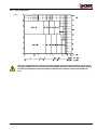
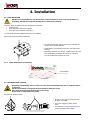
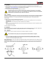
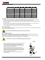
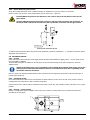
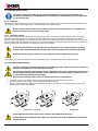
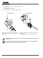
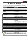
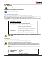
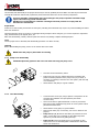
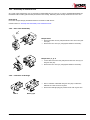
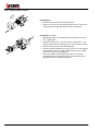
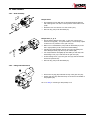
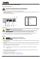
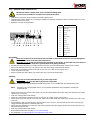
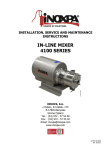
INSTALLATION, SERVICE AND MAINTENANCE INSTRUCTIONS HLR Rotary Lobe Pump INOXPA, S.A. c/Telers, 54 Aptdo. 174 E-17820 Banyoles Girona (Spain) Tel. : (34) 972 - 57 52 00 Fax. : (34) 972 - 57 55 02 e-mail: [email protected] www.inoxpa.com Original Manual 01.504.30.00EN ED.2010/09 EC DECLARATION OF CONFORMITY (according to Directive 2006/42/CE, annex II, part A) INOXPA, S.A. C/ Telers, 54 17820 Banyoles (Girona) - SPAIN Manufacturer: Hereby declares, that the product: LOBE ROTOR PUMP HLR Name Type conforms to the specifications of the Council Directive: Machine Directive 2006/42/CE, and complies with the essential requirements of the Directive and Harmonised Standards: UNE-EN ISO 12100-1/2:2004 UNE-EN 809/AC:2001 UNE-EN ISO 13857:2008 UNE-EN 953:1997 UNE-EN ISO 13732-:2007 Low Voltage Directive 2006/95/EC (what repeal 73/23/CEE Directive), and are conforms with UNE-EN 60204-1:2006 and UNE-EN 60034-1:2004 EMC Directive 2004/108/EC (what repeal 89/336/CEE Directive), and are conforms with UNE-EN 60034-1:2004 In compliance with the Regulations (CE) nº 1935/2004, relating to materials and articles intended to come into contact with foodstuff (repeal Directive 89/109/CEE), the materials in contact with the product do not transfer their components in quantities which may jeopardise consumer’s health or safety Banyoles, 2012 1. Safety 1.1. INSTRUCTION MANUAL This instruction manual contains information on the reception, installation, operation, fitting, stripping and maintenance for the HLR pump. The information given herein is based on the most up-to-date data available. INOXPA reserves the right to modify this instructions manual without having to give prior notice. 1.2. START-UP INSTRUCTIONS This instruction manual contains vital and useful information for properly operating the pump and for keeping it in good running condition. Not only should the safety instructions set forth in this chapter be carefully read before putting the pump into operation, but those concerned must also familiarise themselves with the operating features of the pump and strictly adhere to the instructions given herein. It is extremely important that these instructions be kept in a set place near the installation. 1.3. SAFETY 1.3.1. Warning signs Danger for people in general. Danger of injury caused by rotating parts of the equipment. Danger! Electricity. Danger! Caustic or corrosive agents. Danger! Suspended loads. Danger to the proper operating of the machine. Obligation to ensure safety at work. Use of safety goggles obligatory. 1.4. GENERAL SAFETY INSTRUCTIONS Please read the instruction manual carefully before installing and commissioning the pump. Should you have any doubts or queries, contact INOXPA. 1.4.1. During the installation You must always bear in mind the Technical Specifications set forth in Chapter 8. Do not put the pump into operation before connecting it to the pipes. Do not put the pump into operation if the rotor case of the pump has not been fitted and the lobe rotors fixed in the pump. Check that the motor/drive specifications are correct, especially if there is a special risk of explosion due to the work conditions. During the installation procedure, all the electrical work must be carried out by duly authorised personnel. 1.4.2. During operation You must always bear in mind the Technical Specifications set forth in Chapter 8. The limit values that have been set must NEVER be exceeded. NEVER touch the pump or pipes whenever the pump is being used to transfer hot liquids or during the cleaning procedure. ED.2010/09 1.Safety 3 The pump has moving parts. Do not put your fingers into the pump when it is operating. NEVER work with the suction and the delivery valves shut off. NEVER directly sprinkle the electric motor with water. Standard motor protection is IP-55: dust and water sprinkling protection. 1.4.3. During maintenance You must always bear in mind the Technical Specifications set forth in Chapter 8. NEVER strip the pump down until the pipes have been drained. Remember that there will always be some liquid left in the rotor case (if it has not been fitted with a drain). Always remember that the liquid that has been pumped may be dangerous or subject to high temperatures. For situations of this type, please consult the prevailing regulations in the country in question. Do not leave loose parts on the floor. ALWAYS turn the power supply to the pump off before embarking on maintenance work. Take out the fuses and disconnect the wires from the motor terminals. All electrical work must be carried out by duly authorized personnel. 1.4.4. In accordance with the instructions Any failure to comply with the instructions could lead to a hazard for the operators, the atmospheric conditions of the room, and the machine, and it could lead to a loss to any right to make a claim for damages. Such non-compliance could bring with it the following risks: • Important operating failures of the machine / plant. • Failure to comply with specific maintenance and repair procedures. • Potential electrical, mechanical and chemical hazards. • Atmospheric conditions in the room could be hazardous due to the release of chemical substances. 1.4.5. Warranty We wish to point out that any warranty issued will be null and void and that we are entitled to an indemnity for any civil liability claim for products which might be filed by third parties if: • Operation and maintenance work has not been done following the corresponding instructions; the repairs have not been made by our personnel or have been made without our written authorization; • Modifications are made to our material without prior written authorization; • The parts or lubricants used are not original INOXPA parts/lubricants; • The material has been improperly used due to error or negligence or has not been used according to the indications and the intended purpose. • The parts of the pump have been damaged as a result of having been exposed to strong pressure as there was no pressure relief valve. The General Delivery Terms which you have already received are also applicable. No modification can be made to the machine without the prior consent of the manufacturer. For your safety, use spare parts and original accessories. The use of other parts exempts the manufacturer from any and all responsibility. Any change in operating conditions can only be done with the prior written consent of INOXPA. In the event of doubt or should you require a fuller explanation on particular data (adjustment, assembly, disassembly...), please do not hesitate to contact us 4 1.Safety ED.2010/09 2. Index 1. Safety 1.1. 1.2. 1.3. 1.4. Instruction manual .......................................................................................................... 3 Start-up instructions ........................................................................................................ 3 Safety ............................................................................................................................. 3 General safety instructions ............................................................................................... 3 2. Index 3. General Information 3.1. Description ...................................................................................................................... 6 3.2. Operating principle .......................................................................................................... 6 3.3. Application ...................................................................................................................... 6 4. Installation 4.1. 4.2. 4.3. 4.4. 4.5. 4.6. 4.7. 4.8. 5. Pump reception ............................................................................................................... 8 Transport and storage ..................................................................................................... 8 Location .......................................................................................................................... 9 Coupling ......................................................................................................................... 9 Pipes ............................................................................................................................ 10 Secondary piping ........................................................................................................... 11 Pressure relief valve ...................................................................................................... 12 Electrical installation ...................................................................................................... 12 Start-up 5.1. Start-up ........................................................................................................................ 13 5.2. Pressure By-pass ........................................................................................................... 13 6. Operating Problems 7. Maintenance 7.1. 7.2. 7.3. 7.4. 7.5. 7.6. 7.7. 8. Technical Specifications 8.1. 8.2. 8.3. 8.4. 8.5. 8.6. 8.7. 8.8. 8.9. ED.2010/09 General maintenance ..................................................................................................... 16 Storage ......................................................................................................................... 16 Cleaning ....................................................................................................................... 17 Pump disassembly ......................................................................................................... 18 Pump assembly ............................................................................................................. 21 Lobe adjustment ........................................................................................................... 24 Mechanical seal assembly and disassembly ..................................................................... 26 Technical specifications .................................................................................................. 28 Weights ........................................................................................................................ 30 HLR dimensions............................................................................................................. 31 pump with flushing dimensions ...................................................................................... 33 HLR 0 ........................................................................................................................... 34 HLR 1 ........................................................................................................................... 36 HLR 2 ........................................................................................................................... 38 HLR 3 ........................................................................................................................... 40 HLR 4 ........................................................................................................................... 42 2.Index 5 3. General Information 3.1. DESCRIPTION The HLR rotary lobe pumps by INOXPA are part of our wide range of positive displacement rotary lobe pumps for viscous liquids. The following models exist in the hygienic rotary lobe pump range: • • The HLR pump normal flow rate suitable for differential pressure of up to 12 bar. The HLR with wider lobes, delivers a higher flow rate, and is suitable for differential pressure of up to 7 bar. The HLR model has been specially developed to respond to all hygienic requirements in the Bio-Pharm and Food industries. As regards hygiene, reliability and sturdiness, the complete range of rotary lobe pumps satisfies all requirements set by the aforesaid industries. Its modular design enables optimal part interchange between the different pumps. The rotary lobe pumps are positive displacement pumps. Owing to the contact between the internal parts, the pressure variations, etc. they make a louder noise than centrifugal pumps. This noise must be taken into consideration when installing these pumps. The HLR rotary lobe pumps by INOXPA have been certified by EHEDG and designed so that they meet the requirements of 3A Sanitary Authority. This equipment is suitable for use in food processing applications with strict hygienic requirements. 3.2. OPERATING PRINCIPLE The rotary lobe pump is a positive displacement rotary pump. The left lobe (except in the case of pump size 0) is driven by the driving shaft. The right lobe (except in the case of pump size 0) is located on the driven shaft, and is driven via a helical gear. Both lobes rotate in synchronism without one touching the other. When the pump is running they displace a set volume of liquid. Figure below shows how a rotary lobe pump operates. A: When the lobes rotate, the space on the suction side increases because one lobe moves away from the other, thus causing a partial vacuum that draws the liquid into the pumping chamber. B: Each lobe void is filled consecutively as the shafts rotate and the liquid is displaced towards the discharge side. The small clearances between the lobes, and between the lobes and the walls of the rotor case, duly cause the spaces to be rather well closed. C: The rotor case is completely full and the liquid leaks through the meshing of the lobes, knocking against the space walls so as to thus complete the pumping action. 3.3. APPLICATION The main advantage of the INOXPA HLR rotary lobe pump is its capacity to pump a great variety of viscous liquids, from 1 mPa.s up to 100.000 mPa.s Furthermore, it is capable of pumping liquid products that require very careful handling and liquids that contain soft solids thus causing only a minimum degradation of same. 6 3.General Information ED.2010/09 3.3.1. Field of application P [bar] The range of application for each type of pump is limited. The pump was selected for a given set of pumping conditions when the order was placed. INOXPA shall not be liable for any damage resulting from the incompleteness of the information provided by the purchaser (nature of the fluid, rpm, etc.). ED.2010/09 3.General Information 7 4. Installation 4.1. PUMP RECEPTION INOXPA is not responsible for any deterioration of the material as a result of its transportation or unpacking. Visually check that the packing has not suffered any damage. The pump will be accompanied by the following documentation: • Dispatch notes. • Pump Instruction and Service Manual. • Drive Instruction and Service Manual (*). (*) If the pump has been supplied with a drive from INOXPA. Unpack the pump and check the following: • The pump suction and delivery connections, removing the remains of any packing material. • Check that the pump and the motor have not suffered any damage. • Should the pump not be in proper condition and/or does not have all the parts, the haulier must draw up a report as soon as possible with regard to the same. 4.1.1. Pump identification and marking Serial number Pump plate 4.2. TRANSPORT AND STORAGE HLR pumps and pumping units are often too heavy to be handled manually. Use an adequate means of transport. Use the points which are indicated in the drawing for lifting the pump. Only authorized personnel should transport the pump. Do not work or walk under heavy loads. Lift the pump as shown below: 8 4.Installation • Always use two support points placed as far apart as possible. • Secure the support so that it will not move. • See chapter 8. Technical Specifications to consult dimensions and weights. ED.2010/09 4.3. LOCATION • Position the pump as near as possible to the suction tank, and whenever possible below the level of the liquid. • Place the pump in such a way that there is enough space around it to provide access both to the same and to the motor. (See Chapter 8. Technical Specifications to consult dimensions and weights). • Place the pump on a level and flat surface. • The basement must be rigid, horizontal and against any vibration. Install the pump in such a way that it can be properly ventilated. If the pump is to be installed outside, it must be done so under cover. Its positioning must enable easy access for any inspection and maintenance operations that may need to be carried out. 4.3.1. Foundation Install the pump base so that the drive and pump are level and well supported. Therefore the pump unit should be installed on a base plate –according to DIN 24259-, or on a frame, both placed exactly level on the foundation. The foundation must be hard, level, flat, vibrations free ...to prevent base distortion (to keep the alignment pump –drive guaranteed while commissioning). To install the pump unit on the foundation proceed as follows: • Make holes in the foundation to fit foundation bolts. This is unnecessary when expanding screws are used instead of foundation bolts. • Place base plate or frame with the aid of shims horizontally on the foundation. • Grout • When the grout has entirely hardened the pump unit can be placed on the base plate or the frame. Tighten the nuts on the foundation bolts carefully. For other foundations consult INOXPA. 4.4. COUPLING For the couplings selection and assembly consult to the supplier manual. Sometimes the torque of the positive displacement pumps can be high enough. Therefore, a coupling have been chosen 1.5 to 2 the adequate torque. 4.4.1. Alignment The pump and motor shaft of complete units have been accurately pre-aligned in our factory. After installations of the pump unit, the pump and motor shaft should be re-aligned. • After unit is installed recheck alignment of pump and motor shaft and alignment of piping. Realign if necessary. • In the case of applications dealing with high temperatures the pump can be operated temporarily at its working temperature. Then recheck alignment pump - piping. Place a straight-edge (A) on top of the coupling: the straight should make contact with both halves of the coupling over their entire length. See figure. Repeat the check, but this time on both sides of the coupling near the shaft. For the sake of accuracy, this check should also be done using an outside caliper (B) at two diametrically opposite points on the outside surfaces of the two halves of the coupling. ED.2010/09 4.Installation 9 Maximum alignment deviations: Outside diameter of the coupling [mm] Vamin [mm] Vamax [mm] Vamax - Vamin [mm] Vr. [mm] 70 - 80 2 4 0,13 0,13 81 - 95 2 4 0,15 0,15 96 - 110 2 4 0,18 0,18 111 - 130 2 4 0,21 0,21 131 - 140 2 4 0,24 0,24 141 - 160 2 6 0,27 0,27 161 - 180 2 6 0,3 0,3 181 - 200 2 6 0,34 0,34 201 - 225 2 6 0,38 0,38 4.5. PIPES • In general, suction and delivery pipes should be fitted in straight stretches, with the minimum amount of elbows and accessories, in order to reduce, as far as possible, any head loss that might be produced by friction. • Make sure that the pump ports are well aligned with respect to the piping and that they are similar in diameter to that of the pipe connections. • Position the pump as near as possible to the suction tank, and whenever possible below the level of the liquid or even lower with respect to the tank in order for the static suction head to be at its maximum. • Place brackets for the piping as near as possible to the suction and delivery ports of the pump. 4.5.1. Shut-off valves The pump can be isolated for the purpose of carrying out maintenance work. To this end, shut-off valves should be fitted at the pump’s suction and delivery connections. These valves must ALWAYS be open whenever the pump is operating. 4.5.2. Self-priming process In general terms --if the self-priming process is followed-- the pump ought to contain sufficient liquid to fill the internal recesses and the void spaces thus enabling the pump to create a pressure difference. However, if low viscosity fluids are to be pumped, a foot valve of the same or greater diameter as that of the suction pipe should be installed; alternatively, the pump can be installed with a "U" shaped piping. The use of a foot valve is not recommended for pumping viscous liquids. • In order to eliminate air and gases from the suction pipe, the counterpressure on the discharge pipe should be reduced. When the selfpriming process is used, the pump's start-up should be done by opening and emptying the discharge pipe which allows the air and gases to escape at a low counter-pressure. • Another possibility involves long pipes or when a check valve is installed in the discharge pipe; it is also possible to install a by-pass with a shut-off valve on the discharge side of the pump. This valve shall be opened in the case of priming and will allow air and gases to escape at a minimum counter-pressure. • The by-pass should not lead back to the intake orifice but to the supply tank instead. 10 4.Installation ED.2010/09 4.5.3. Barrier fluid with pressure tank As the HLR Double Mechanical seal is of balanced design, the installation of a pressure tank is not necessary. Pressure tank is only necessary if the pumped liquid, process safety rules… requires it. Install ALWAYS the pressure tank between 1 and 2 meters above the mechanical seals. See the figure below. 1...2m Connect ALWAYS the barrier fluid input connection with the bottom chamber seal connection. So, the barrier fluid outlet will be carried out by the top chamber connection. See the figure below Mechanical seal Pressure tank connection lay out To obtain further information about the pressure tank (installation, operation, maintenance, …), consult the instruction manual supplied by the manufacturer. 4.6. SECONDARY PIPING 4.6.1. Quench If the seal requires flush media, the media supply and the purchase and installation of piping, valves ... for the media are not the responsibility of INOXPA. The flush shaft seal option is available on all seal types. Use the sectional drawings of the HLR seal options to purchase additional parts. Attention should be given to the compatibility of the handled liquid with the flush media. Choose the sealing liquid so that unwanted chemical reactions are avoided. Also check the compatibility of the flush media with seal elastomers. HLR rotor cases have female threaded inlet and outlet connections and are dependent upon frame of the pump and type of quench system employed. 4.6.2. Liquid flush media Use a flush media which is filtered free from impurities to obtain maximum service life of the seal. If the product is sticky or crystalline then use media which is able to dissolve the product. Connect the quench so that the inlet is at the bottom and outlet is at the top. This will make a better evacuation or air or gases possible. 4.6.3. Heating / cooling jackets Heating / cooling jackets (S) are available on the front cover. Heating or cooling media can be provided via connections according to the next figure. ED.2010/09 4.Installation 11 4.7. PRESSURE RELIEF VALVE The positive displacement lobe pumps must be protected from excess pressure when they are operating. Consequently, all the HLR pumps can be fitted with a stainless steel pressure relief valve or a pressure by-pass 4.7.1. Protection This valve protects the pump and prevents excessively high pressure arising in the circuit. It reduces the differential pressure (Δp) between suction and discharge, but not the maximum pressure within the plant. Do not use the pressure relief valve to protect the system from excess pressure. It is designed to protect the pump only as it is not a safety outlet. 4.7.2. Operation principle The pressure by-pass valve is located in the rotor case and prevents excess pressure arising inside the pump. For example, when the pump's discharge port is clogged and the liquid cannot be pumped out, too high a pressure can cause serious damage to some of the pump's parts. The pressure relief valve opens a passage from the pump's discharge side to its suction side: an escape route, redirecting the flow again to the suction side whenever specifically high pressure levels are reached. The by-pass is effective in both directions of rotation (only front cover assembly). If the relief valve operates, this will mean that the equipment is not working properly. The pump should be disconnected immediately. Identify and solve the problem before re-starting the pump. Remember that the pressure relief valve is not able to be used to regulate the flow rate. The pressure relief valve can be adjusted to any determined pressure, according to the type of pump being used. 4.8. ELECTRICAL INSTALLATION Leave the connecting of the electrical motors to qualified personnel. Take the necessary measures to prevent any breakdowns in the connections and wires. The electrical equipment, the terminals and the components of the control systems may still carry an electric charge even when disconnected. Contact with them may put the safety of operators at risk, or cause irreparable damage to the material. Before manoeuvring the pump, make sure that the electric box is switched off. • • • Connect the motor in accordance with the instructions supplied by the manufacturer of the same. Check the direction of the rotation (see the signalling label on the pump). Start the pump motor briefly. Make sure the pumping direction is the right one. If the pump operates in the wrong direction it may cause severe damage. Pumps size 1, 2, 3, and 4 Pumps size 0 Check ALWAYS the direction of the motor’s rotation with liquid inside the pump. For the models with sealing chamber, make sure always that it is filled of liquid before checking the rotating direction. 12 4.Installation ED.2010/09 5. Start-up Before putting the pump into operation read carefully the instructions on installation given in Chapter 4. Installation. 5.1. START-UP Read Chapter 8. Technical Specifications carefully. INOXPA will not assume responsibility for any improper or incorrect use of the equipment. Do not touch the pump or the piping while it is pumping products at a high temperature. 5.1.1. Checks to be carried out before putting the pump into operation • Completely open the pipes’ suction and delivery shut-off valves. • Check oil level of the pump. Add correct grade of oil as necessary to maintain level in center of oil sight glass (In the case of first start-up: pumps are shipped with oil in the gearbox). • If the liquid fails to flow toward the pump, fill it with the liquid to be pumped. The pump must NEVER rotate without fluid inside it. • Check that the power supply matches the rating indicated on the motor plate. • Check that the direction of rotation of motor is the right one. • If the pump has a single or double mechanical seal with buffer or barrier fluid, mount the auxiliary connection corresponding to the values indicated in Chapter 8, Technical Specification. 5.1.2. Checks to be carried out on putting the pump into operation • Check to make sure that the pump is not making any strange noises. • Check to see if the absolute inlet pressure is sufficient, in order to avoid cavitations in the pump. Consult the curve for the minimum required pressure above the steam pressure (NPIPr). • Monitor the delivery pressure. • Check that there are no leaks in the sealed areas. A shut-off valve should not be used in the suction pipe to regulate the flow rate. It must be completely open during operation. Monitor motor consumption in order to avoid a circuit overload. Reduce flow and motor power consumption by reducing motor speed. 5.2. PRESSURE BY-PASS When pump has a pressure by-pass, pump only can rotate in one direction. To reverse the direction of the pump’s rotation, the assembly of the by-pass must also be reversed. The valve's opening pressure depends on the fluid to be pumped, its viscosity, its rpm ..., and so before starting-up the pump, the operator ought to adjust the pressure relief valve's opening pressure. When an overflow valve or a pressure bypass is installed, the valve is adjusted to the maximum working pressure of the pump. The end user must adjust the valve to the correct pressure. When an overflow valve or a pressure bypass does not operate properly, the pump must immediately be removed from service for repair. The valve must be examined by the INOXPA technical assistance personnel. ED.2010/09 5.Start-up 13 5.2.1. External Assembly When installing a pressure relief valve, some points shall be considered: • • To avoid dead legs Drainability of the pump and pipeline Please see figure below where recommended installation is shown: Wrong Installation Correct installation Example of standard Pressure Relief Valve installation. This arrangement creates a dead leg with a large amount of product. Example of Hygienic NCS Pressure Relief Valve installation, with air actuated rising. It allows pump and pipeline to drain, avoiding dead areas. When checking the relief valve also make sure the pump's pressure will NEVER exceed the pressure setting + 2 bar. When the relief valve does not work properly, the pump must be taken out of service immediately. The valve must be inspected by an INOXPA service technician. 14 5.Start-up ED.2010/09 6. Operating Problems The table given below provides solutions to problems that might arise during pump operation. With respect to the same, it is assumed that the pump has been properly installed and has been correctly selected for the application in question. Should there be a need for technical service please contact INOXPA. Operating problems Probable causes Motor Overload Insufficient discharge flow rate No pressure on the discharge side Irregular discharge flow rate/pressure Noise and vibrations The pump gets clogged Overheating of pump Abnormal wear Leak through mechanical seal 8, 9, 12, 16, 20, 21, 22, 23, 24, 26. 2, 4, 5, 7, 8, 9, 10, 11, 13, 14. 1, 2, 3, 6, 7. 2, 4, 5, 6, 9, 12. 2, 4, 5, 6, 7, 8, 9, 11, 12, 13, 16, 19, 20, 21, 22, 23, 24, 25, 26. 8, 9, 11, 16, 19, 20, 21, 22, 24, 25, 26. 7, 8, 9, 11, 12, 16, 20, 21, 22, 23, 24, 26. 4, 5, 11, 15, 16, 19, 24, 25. 17, 18. Probable causes Solutions 1 2 Wrong rotation direction Insufficient NPIP 3 4 5 6 7 8 Pump not purged Cavitation The pump sucks in air Suction pipe clogged Wrong setting of pressure relief valve Discharge pressure too high 9 Viscosity of the liquid is too high 10 Viscosity of liquid too low. 11 12 13 14 15 16 17 18 Temperature of liquid too high. Pump speed too high The lobes are worn Pump speed too low Product very abrasive Worn bearings Worn or damaged mechanical seal O-rings and gaskets are not the right ones for the liquid Worn gears Insufficient lubricating oil level Unsuitable lubricating oil The lobes rub 19 20 21 22 23 24 25 26 Coupling misalignment Tension on the pipelines Foreign bodies in the liquid Pump and / or electric motor not fixed on foundation Invert the rotation direction Increase available NPIP: • Rise the suction tank • Lower the pump • Reduce the speed • Increase the diameter of the suction pipe • Shorten and simplify the suction piping. Purge or fill Increase suction pressure ( see 2) Check suction pipe and all its connections. Check the suction pipe and filter(s), if any. Check the pressure relief valve's setting If necessary, reduce the loss of head by increasing the diameter of the discharge pipe • Reduce the pump speed • Reduce the viscosity, for example, by heating the liquid. • Increase the pump speed • Increase the viscosity, for example, by cooling the liquid. Reduce the temperature by cooling the liquid. Reduce the pump speed Replace the lobes Increase the pump speed Fit hardened lobe hubs Replace the bearings, check the pump Replace the seal Fit the proper O-ring and gaskets; check with the supplier. Replace and readjust the gears Fill up with oil Use an appropriate oil • Reduce the temperature • Reduce the discharge pressure • Adjust the clearance Align the coupling Connect the pipelines to the pump free of tensions Insert a filter in the suction pipe Tighten, check that the piping has been connected stressfree and align the coupling If the problem persists, use of the pump must cease immediately. Contact the pump’s manufacturer or its representatives. ED.2010/09 6.Operating Problems 15 7. Maintenance 7.1. GENERAL MAINTENANCE This pump, as with any other machine, needs to be maintained. The instructions contained in this manual deal with the identification and replacement of the spare parts. These instructions have been drawn up by maintenance staff and are destined for those people who are responsible for supplying spare parts. Read carefully Chapter 8. Technical specifications. All the parts or materials that are changed must be duly eliminated / recycled in accordance with the prevailing directives in each area. ALWAYS disconnect the pump before starting out on any maintenance work. 7.1.1. Check the mechanical seal Periodically check that there are no leaks in the shaft area. Should there be any leaks in the mechanical seal area, replace the same pursuant to the instructions given in the Pump Disassembly and Assembly sections. 7.1.2. Dry thread torque Material Dry thread torque [N.m.] M5 M6 M8 M10 M12 M14 M16 M18 M20 8.8 6 10 25 49 86 135 210 290 410 A2 5 9 21 42 74 112 160 210 300 7.1.3. Oiling The bearings are oiled by immersion in an oil bath. The pumps are supplied with oil. • Regularly check the oil level, for example, weekly or every 150 operating hours. • The first oil change must be carried out after 150 hours of operation. • Afterwards, it can be changed every 2500 operating hours or at least once a year when operating under normal conditions. When change the oil: the oil sump must be filled up to the level in the middle of the peephole. Do not pour too much oil into the sump. Leave the pump switched off for a while and then re-check the oil level; if necessary, add a little oil. Oils for environment temperatures of 5 to 50ºC: SAE 90 or ISO VG 220 PUMP SIZE Quantity of oil in the gear case (l.) HLR 0 0,3 HLR 1 0,5 HLR 2 0,75 HLR 3 1,75 HLR 4 4,5 7.2. STORAGE Before being stored the pump must be completely emptied of liquids. Avoid, as far as possible, the exposure of the parts to excessively damp atmospheres. 16 7.Maintenance ED.2010/09 7.3. CLEANING 7.3.1. Manual cleaning The use of aggressive cleaning products such as caustic soda and nitric acid may give rise to skin burns. Use rubber gloves during the cleaning process. Always use protective goggles. 7.3.2. Automatic CIP (cleaning-in-place) If the pump is installed in a system fitted with a CIP process, there will be no need for stripping. The recommended minimum liquid speed for an effective process of cleaning is 1,8 m/s (minimum Re > 100 000 at 1,0~2,5 bar). It is recommended to run the pump during the CIP process (rotation speed ~ nominal speed at 50 Hz). If it is not fitted with an automatic cleaning process, strip the pump pursuant to the instructions given in the section entitled Stripping and Assembly of the pump. Cleaning solutions for CIP processes. Only use clear water (chloride free) to mix with the cleaning agents: a) Alkaline solution: 1% in weight of caustic soda (NaOH) to 70ºC (150ºF) 1 kg NaOH + 100 l. water = cleaning solution or 2.2 l. NaOH to 33% + 100 l. of water = cleaning solution b) Acid solution: 0.5% in weight of nitric acid (HNO3) to 70ºC (150ºF) or 0.7 litres HNO3 to 53% + 100 l. water = cleaning solution Monitor the concentration of cleaning solutions; it could give rise to the deterioration of the pump sealing gaskets. These solutions are given as examples and should be validated before use on an application. In order to remove any remains of cleaning products, ALWAYS rinse the element in question with clean water after completing the cleaning process. 7.3.3. Automatic SIP (sterilization-in-place) The process of sterilization with steam is applied to all the equipment including the pump. Do NOT start the pump during the process of sterilization with steam. The parts/materials suffer no damage if the indications specified in this manual are observed. No cold liquid can enter the pump till the temperature of the pump is lower than 60°C (140°F). A flow by-pass is recommended to be used in order to assure the flow of sterile product after the pump. Maximum conditions during the SIP process with steam or overheated water a) b) c) d) ED.2010/09 Max. temperature: Max. time: Cooling: Gasket materials: 140°C (284°F) 30 min Sterile air or inert gas EPDM / PTFE (recommended) FPM / NBR (not recommended) 7.Maintenance 17 7.4. PUMP DISASSEMBLY The assembly and disassembly of the pumps should only be done by qualified personnel. Make sure that the personnel read carefully this instruction manual and, in particular, those instructions which refer to the work they will perform. Incorrect assembly or disassembly may cause damage in the pump's operation and lead to high repair costs and a long period of down-time. INOXPA is not responsible for accidents or damages caused by a failure to comply with the instructions in this manual. Preparations Provide for a clean working environment as some parts, including the mechanical seal, require very careful handling and others have close tolerances. Check that the parts which are used are not damaged during transport. When doing this, you need to inspect the adjustment edge, the butted faces, the tight fit, burrs, etc. After each disassembly, carefully clean the parts and check for any damage. Replace all damaged parts. Tools Use the proper tools for assembly and disassembly operations. Use them correctly. Cleaning Before disassembling the pump, clean it on the outside and on the inside. NEVER clean the pump by hand when it is running 7.4.1. Pump cover disassembly CAUTION! Liquid may spill from the rotor case when removing the pump cover. Close the suction and delivery valves. Remove the cap nuts (45). Indents have been provided at four points around the perimeter of the pump cover (03) to assist, if necessary, in removing it from the rotor case (that is, with the help of a screwdriver). Check that the seal (80A) is in good condition. Loosen the lobe screws (25) using a spanner. This spanner can be requested from INOXPA. See spare parts list (Document: 01.504.31.000) These screws have a right-hand thread. In order to prevent the lobes from turning simultaneously, blocks of wood or plastic can be placed between the lobes. Check that the O-ring (80) is in good condition. Remove both lobes (02). If necessary, use a tool to assist for this purpose. Pump size 1, 2, 3, 4: Remove the shims (32) mounted on each shaft. If more than one is mounted on each shaft, keep them separate to prevent them from getting mixed up. Pump size 0: Remove the shaft sleeve (13) mounted on each shaft. Sleeves are not interchangeable. Remember the shaft each sleeve was mounted on. 7.4.2. Lobe disassembly 18 7.Maintenance ED.2010/09 7.4.3. Disassembly of mechanical seals As a result of the pump design, it is not necessary to disassemble the rotor case (01) in order to assemble/disassemble the mechanical seals. Rotatory part is directly mounted to lobe housing. Stationary part is directly mounted to the rotor case. Pump size 0 Due to the compact design, Mechanical Seals are mounted on shaft sleeves. Consult section 7.7 Assembly and Disassembly of the Mechanical Seals 7.4.4. Rotor case disassembly Pumps Size 0: • Remove the Allen screws (51B) that fix the rotor case to the gear case (06). • Remove the rotor case (01) using Nylon hammer if necessary. Pumps Size 1, 2, 3, 4: • Loosen and remove the nuts (54A) that fix the rotor case (01) to the gear case (06). • Remove the rotor case (01) using Nylon hammer if necessary. • Place a container underneath the gear case (06) to collect the lubricant oil so that it can be recycled. • Remove the drainage plug (87) located to the rear of gear case. 7.4.5. Lubrication oil drainage HLR 0 ED.2010/09 HLR 1,2,3,4 7.Maintenance 19 7.4.6. Shaft assembly removal Pumps Size 0: • Remove the key (61A) from the driveshaft (05). • Remove the screws (51C) and dismount the rear cover (12B) while checking that the O-ring (80E) does not stick to both sides. Pumps Size 1, 2, 3, 4: 20 • Identify the position of the driveshaft (05) and whether it is in the left or right position. • Remove the screws (52) – the screws (51D) at pump size 1 - and washers (53A) that fix the bearings cover (12) to the gear case (06). • Remove the key (61A) from the driveshaft (05). • Remove the shaft assembly from the gear case. Due to the tightness of the bearings cover (12), a Nylon hammer must be used. Lightly tap the rear part of the driveshaft (05). • Check the condition of the Klingerit seal (18A) once the shaft assembly has been removed, and if there are any defects, find a replacement before reassembling the pump. 7.Maintenance ED.2010/09 7.5. PUMP ASSEMBLY 7.5.1. Shaft assembly Pumps Size 0: • Check that the O-ring (80E) has not been damaged and attach it with a little grease or oil in the correct position of the bottom cover (12B). • Attach the rear cover and fix it on with screws (51C). • Place the key (61A) in the driveshaft (05). Pumps Size 1, 2, 3, 4: • Ensure that the Klingerit seal (18A) - in the case of pump size 4 check the O-ring (80E) - is in good condition, or if necessary replace it with a new one, and fit it to the gear case (06). • Make sure to reassemble the pump with the driveshaft (05) in the left or right position just as it was before disassembling. • Introduce the shaft assembly into the gear case (06) taking care when sliding the shaft (05) driven by the retainer (88). • Use a Nylon hammer and lightly tap the shafts (05 and 05A) until the bearings cover (12) is well fixed to the gear case (06). • Fix the bearings cover (12) to the gear case (06) with the washers and screws (53A and 52). • Place the key (61A) in the driveshaft (05). • Remove the oil plug (85) located at the top of the gear case (06). • Fill the gear case (06) with lubricant up to the level in the middle of the peephole (86). 7.5.2. Filling with lubricant oil See 7.1.3 Oiling to consult type and quantity of oil. ED.2010/09 7.Maintenance 21 7.5.3. Rotor case assembly CAUTION! When reassembling the rotor case, pay attention to the position of the centring pins. Pumps Size 0: • Mount the rotor case (01) on the gear case (06). Due to the tightness of the pins, it is necessary to use a Nylon hammer. Lightly tap the rotor case until it is tight to the gear case. • Attach the allen screws (51B). • Tighten the nuts with the appropriate tightening torque. Pumps Size 1, 2, 3, 4: • Mount the rotor case (01) on the gear case (06). Due to the tightness of the pins, it is necessary to use a Nylon hammer. Lightly tap the rotor case until it is tight to the gear case. • Attach the nuts (54A) with the washers (53). • Tighten the nuts with the appropriate tightening torque. 7.5.4. Assembly of mechanical seals Consult section 7.7 Assembly and disassembly of the mechanical Seals 7.5.5. Lobe assembly ALWAYS check the clearance between the lobes and lobes and rotor case before finishing assembly. See 7.6.1 Clearance and tolerance table HLR 0 • Fit new O-rings (80) to the lobe screws (25) • Lubricate the rings with soapy water or edible oil compatible with the material of the O-rings, pumped liquid and application. • Fit the shims (32) on the shafts (05 and 05A). • See chapter 7.6.3 Lobe/Pump Rotor case adjustment using shims. • Place the lobes (02) on the shafts (05 and 05A) ensuring that the lobe and shaft markings (numbers 0 and 1) coincide. • Tighten the lobe screws (25) using a spanner. In order to prevent the lobes from turning simultaneously, blocks of wood or plastic can be placed between the lobes. • Assembly is exactly the same for all lobe types. HLR 1, 2, 3, 4 7.5.6. Pump cover assembly 22 7.Maintenance ED.2010/09 ED.2010/09 • Check that the O-ring (80A) is in good condition or, if applicable, replace it with a new one. • Place it in the pump rotor case (01) ensuring that no dirt or residue of any product remains in the seal or the rotor case. • If it is necessary to lubricate the O-ring to assist in fitting it, use soapy water or edible oil compatible with the material of the O-ring, pumped liquid an application. • Place the pump cover (03) onto the rotor case (01) and tighten the blind nuts (45). • See chapter 5.1.1 Checks to be carried out before putting the pump into operation 7.Maintenance 23 7.6. LOBE ADJUSTMENT AND SYNCHRONISING 7.6.1. Clearance and tolerance table (mm) HLR 0-20 HLR 0-25 HLR 1-25 HLR 1-40 HLR 2-40 HLR 2-50 HLR 3-50 HLR 3-80 HLR 4-100 HLR 4-150 A B C D E 0,12 ±0,05 0,15 ±0,05 0,15 ±0,05 0,15 ±0,05 0,2 ±0,05 0,2 ±0,05 0,25 ±0,05 0,3 ±0,05 0,35 ±0,05 0,5 ±0,05 0,07 ±0,03 0,08 ±0,03 0,1 ±0,05 0,1 ±0,05 0,15 ±0,05 0,15 ±0,05 0,2 ±0,05 0,2 ±0,05 0,35 ±0,05 0,35 ±0,05 0,15 ±0,05 0,2 ±0,05 0,15 ±0,05 0,2 ±0,05 0,15 ±0,05 0,2 ±0,05 0,2 ±0,05 0,3 ±0,1 0,4 ±0,1 0,6 ±0,1 0,15 ±0,05 0,15 ±0,05 0,15 ±0,05 0,15 ±0,05 0,15 ±0,05 0,15 ±0,05 0,2 ±0,05 0,2 ±0,05 0,3 ±0,05 0,3 ±0,05 0,35 ±0,05 0,4 ±0,05 0,35 ±0,05 0,4 ±0,05 0,35 ±0,05 0,4 ±0,05 0,4 ±0,1 0,5 ±0,1 0,85 ±0,1 1,05 ±0,1 A = axial clearance between the lobe and the cover. B = axial clearance between the lobe and the rear of the rotor case. C = radial clearance between the lobe and the rotor case. D = radial clearance between the lobes. E = radial clearance between the lobe and the rotor case on the suction side. Dimensions in mm 7.6.2. Synchronising the lobes 24 • In order to enable the lobes to be tightened, it is necessary to remove the shaft assembly from the gear case (except in the case of pump size 0), and mount the lobes (02) on the shafts fixing them with screws (25). • Loosen the tightening screws from the adjustable fastening mechanism for the idler gear (19A). In principle, the adjustable fastening mechanism is easy to disassemble. It is now possible to rotate the driveshaft (05) while holding the idler shaft still (05A). 7.Maintenance ED.2010/09 Pumps size 0-1 Pumps size 2 Pumps size 3-4 Pumps Size 0, 1, and 2: the adjustable fixing mechanism consists of three pieces: Allen screws (51A), bearing cones (65A), and impeller bushing (17B). Pumps Size 3 and 4: the adjustable fixing mechanism is a single piece (65). Position 1 • Slide the lobes (02) over the shafts (05 and 05A) as indicated in 7.5.5 Lobe assembly • Turn the lobes to the position indicated in position 1 until the gap is as indicated in 7.6.1. Clearance and tolerance table • Tighten manually several tightening screws in the adjustable fixing mechanism. • Then turn the left lobe about 60o in anti-clockwise direction (position 2). Check that the gap in this position is equal to the position 1. If not, these gaps should be equalised by turning one lobe slightly while holding the other still. Position 2 • Tighten the tightening screws of the adjustable fixing mechanism diagonally by 2 or 3 turns with the established tightening torque. • When tightening the screws of the adjustable fixing mechanism, ensure that the gears (19 and 19A) do not turn in relation to each other. This can be avoided by placing a wooden wedge between the gears (19 and 19A). • Check again the gap between the lobes (02) and turn the driveshaft (05) a few times in order to check that the lobes (02) do not rub against one another at any point. • Remove the lobes (02) from the shafts (05 and 05A). • Apply a little lubricant to the driveshaft (05) at the location of the retainer (88) once assembly is finished. 7.6.3. Lobe/Pump Rotor case adjustment using shims • This is the final adjustment to be carried out. The pump must be synchronised and the pump rotor case must be mounted on the gear case. Pumps Size 0: • Due to its small size, and the low assembly tolerances, this pump does not use shims. The length of the sleeves (13) must be adjusted for each pump. Pumps Size 1, 2, 3, 4: • The adjustment is made using ring-shaped shims (32) placed between shaft (05 and 05A) and the lobe (02). • There are 3 different shim thicknesses (0,1, 0,15 and 0,2 mm). • • ED.2010/09 Mount the lobes (02) and tighten the screws (25) as described in 7.5.5. Lobe assembly. Check the tolerances between the lobe and rotor case (A and B). See 7.6.1. Clearance and tolerance table. If they are out of range, change the shims until the necessary clearance is achieved. 7.Maintenance 25 7.7. MECHANICAL SEAL ASSEMBLY AND DISASSEMBLY 7.7.1. Single mechanical seal Mechanical seals are fragile parts. Take care when handling them. Do not use any screwdriver or similar tool to pull out the parts. • • • Clean all the components of the mechanical seal before placing them. Check that the working surfaces are not damaged. INOXPA recommends replacing the entire mechanical seal if one of the working surfaces has a defect. Replace the O-rings during assembly. Pos. Description Single mechanical seal 01 Rotary part 02 Stationary part 03 O-ring 04 Washer 05 Drive Ring 06 Wave Spring 07 O-ring Disassembly Pump size 0: Remove the shaft sleeve (13) mounted on each shaft. Sleeves are not interchangeable. Remember the shaft each sleeve was mounted on. Pump size 1, 2, 3, 4: Remove the shaft shims (32) mounted on each shaft. If more than one is mounted on each shaft, keep them separate to prevent them from getting mixed up. • • Normally the Rotary Assembly (01) remains housed in the lobe rotor during disassembly. Remove them carefully. Remove the stationary parts (02 + 05) from the rotor case bores along. Please proceed carefully. Assembly Pump size 0: Fit the sleeves (13) on each origin shaft. Pump size 1, 2, 3, 4: Fit the shims (32) on each origin shaft. • Lubricate all the O-rings of the mechanical seal with soapy water or oil compatible with the material of the seals, pumped liquid and application. • Mount the drive ring (05) into the rotor case bore, taking care to align it with the 4 seal washer located in the back of the rotor case. • Fit the stationary part (02) with the drive ring (05) into the rotor case bore, ensuring that the pins of the drive ring (05) engage with the biggest slots of stationary part (02). Note: Pumps size 0. Be sure that shaft sleeves (13) are already assembled on the pump before mounting the mechanical seal. • Mount the rotary assembly (01) to the lobe rotor ensuring that the pins of the lobe rotor engage with the slots of the rotary assembly, and it remains perfectly flat. • Clean the working surfaces with solvent. • Reassemble the lobe rotor according to 7.5.5 Lobe assembly. • See paragraph 7.6.3 Lobe/Pump Rotor case adjustment using shims. 26 7.Maintenance ED.2010/09 7.7.2. Balanced double mechanical seal Mechanical seals are fragile parts. Take care when handling them. Do not use any screwdriver or similar tool to pull out the parts. • • • Clean all the components of the mechanical seal before placing them. Check that the working surfaces are not damaged. INOXPA recommends replacing the entire mechanical seal if one of the working surfaces has a defect. Replace the O-rings during assembly. Pos. Description Double mechanical seal 01 Rotary part 02 Stationary part 03 O-ring 04 Washer 05 Static Holder 06 Insert 07 Insert 08 O-ring 09 Grub screw 10 Drive ring 11 Wave Spring 12 Rotary Holder 13 Wave Spring 14 O-ring Disassembly Pump size 0: Remove the shaft sleeve (13) mounted on each shaft. Sleeves are not interchangeable. Remember the shaft each sleeve was mounted on. Pump size 1, 2, 3, 4: Remove the shims (32) mounted on each shaft. If more than one is mounted on each shaft, keep them separate to prevent them from getting mixed up. • • • • • Normally the Rotary Assembly (01) remains housed in the lobe rotor during disassembly. Remove them carefully. Remove the stationary parts (02 + 05) from the rotor case bores along. Please proceed carefully. Remove the 4 seal washers located to the rear of rotor case. Or, 4 Allen screws at pump size 0. Loosen the grub screws (09). Remove carefully the rotary holder (12) and the drive ring (10) from the shafts along. Assembly Pump size 0: Fit the shaft sleeves (13) on each origin shaft. Pump size 1, 2, 3, 4: Fit the shims (32) on each origin shaft. • Lubricate all the O-rings of the mechanical seal with soapy water or oil compatible with the material of the seals. Note: • • • • • • • • • Pump size 0. Be sure that shaft sleeves (13) are already assembled on the pump before mounting the mechanical seal. Mount the drive ring (10) and the rotary holder (12) onto the pump shafts as far as they will go and fix them to the shafts with the grub screws (09). Clean the working surfaces with solvent. Mount the 4 seal washers located to the rear of rotor case. Or, 4 Allen screws at pump size 0. Mount the drive ring (05) into the rotor case bore, taking care to align it with the 4 seal washer located in the back of the rotor case. Fit the stationary part (02) with the drive ring (05) into the rotor case bore, ensuring that the pins of the drive ring (05) engage with the biggest slots of stationary part (02). Mount the rotary assembly (01) to the lobe rotor ensuring that the lobe pins engage with the slots of the rotary face (01), and it remains perfectly flat. Clean the working surfaces with solvent. Reassemble the lobe rotor according to 7.5.5 Lobe assembly. See paragraph 7.6.3 Lobe/Pump Rotor case adjustment using shims. ED.2010/09 7.Maintenance 27 8. Technical Specifications 8.1. TECHNICAL SPECIFICATIONS Short rotor Long rotor Theoretical displacement volume x 100 rev. ............................. Maximum flow rate ................................................................. 217 litres 52 m3/h (229 US gpm) 321 litres 77 m3/h (339 US gpm) Maximum differential pressure ................................................. 12 bar (174 psi) 7 bar (102 psi) Maximum working pressure ..................................................... 16 bar (232 psi) 16 bar (232 psi) Maximum temperature Maximum viscosity (2) (1) ....................................................... (recommended) ..................................... 120 °C (248 ºF) 120 °C (248 ºF) 100.000 mPa.s 100.000 mPa.s Maximum speed ..................................................................... 950 rpm 950 rpm Maximum connections ............................................................. 100 mm (4 in) 150 mm (6 in) Suction / delivery connections ................................................. Clamp (standard) Clamp (standard) (1) (2) Maximum temperature for continuous application due to EPDM gaskets and standard lobe rotor clearances. To consult for higher temperatures. The maximum viscosity allowed will depend on the nature of the liquid and the sliding speed of the seal faces. Consult INOXPA should the viscosity be still greater. Use special protection when the noise level in the operation area exceeds 85 dB(A). PUMP SIZE nmax. [rpm] B1 [mm] D1 [mm] Vs-100 [l] Qth [m3/h] Pmax. [bar] Vu [m/s] Vi [m/s] HLR 0-20 950 21 47,8 2,1 1,8 12 3,6 1,7 HLR 0-25 950 29 47,8 3,0 1,7 7 2,3 0,9 HLR 1-25 950 30 69,1 10,0 5,7 12 3,4 2,9 HLR 1-40 950 42 69,1 13,9 7,9 7 3,4 1,9 HLR 2-40 950 42 87,6 23,4 13,3 12 4,3 3,2 HLR 2-50 950 54 87,6 30,1 17,1 7 4,3 2,4 HLR 3-50 720 54 131,5 67,7 29,3 12 4,9 4,1 HLR 3-80 720 76 131,5 95,3 41,2 7 4,9 2,2 HLR 4-100 400 104 169,7 217,2 52,13 10 3,5 1,8 HLR 4-150 400 154 169,7 321,7 77,21 5 3,5 1,2 nmax. B1 D1 Vs-100 Qth Pmax. Vu Vi 28 Maximum speed Lobe width Lobe diameter Theoretical displacement volume x 100 rev Theoretical flow rate at nmax. Maximum differential pressure Peripheral speed Maximum inlet velocity 8.Technical Specifications ED.2010/09 Materials Product wetted parts .............................................................. Other parts in stainless steel .................................................... Product wetted gaskets .......................................................... Other materials for optional gaskets ......................................... Product wetted parts surface finishing ..................................... AISI 316L AISI 304 EPDM Consult your supplier Ra < 0,8 μm Mechanical seal Type of seal ........................................................................... Rotary parts material .............................................................. Stationary parts material ........................................................ Elastomers material ................................................................ Single internal balanced mechanical seal Silicon carbide Carbon EPDM Cooled mechanical seal Working pressure .................................................................... Flow rate of the circulation ...................................................... 0,5 bar (73 psi) 2,5-5 l/min (0,7-1,3 US gpm) Double mechanical seal Type of seal ........................................................................... Due to the balanced design, no over pressure is required Operating pressure (if it is required by the process) ................. Heating jacket Maximum temperature ............................................................ Maximum pressure .................................................................. ED.2010/09 Balanced design 1,5-2 bar (22-29 psi) over the pump operating pressure 180 ºC (356 ºF) 4 bar (58 psi) 8.Technical Specifications 29 8.1.1. Size of the particles WARNING! Only soft particles. < 10 % damage when using trilobe geometry. < 2 % damage when using wing lobe geometry. Pump size Internal diameter connection [mm] HLR 0-20 15,8 HLR 0-25 HLR 1-25 Maximum theoretical Recommended maximum sphere frame theoretical sphere frame [mm] [mm] 7,5 2,5 22,4 7,5 2,5 22,4 20,6 7 HLR 1-40 35,1 20,6 7 HLR 2-40 35,1 25,6 9 HLR 2-50 47,8 25,6 9 HLR 3-50 47,8 38,5 13 HLR 3-80 72,2 38,5 13 HLR 4-100 97,6 45,6 15 HLR 4-150 150 45,6 15 8.1.2. Torque Maximum torque in the pump shaft. Pump size (N.m.) HLR 0 35 HLR 1 53 HLR 2 108 HLR 3 400 HLR 4 1200 8.2. WEIGHTS Pump size 30 Pump with bare shaft end [kg] HLR 0-20 12,7 HLR 0-25 13,5 HLR 1-25 19,2 HLR 1-40 20,2 HLR 2-40 29,3 HLR 2-50 30,7 HLR 3-50 66,1 HLR 3-80 70,6 HLR 4-100 170,2 HLR 4-150 186 8.Technical Specifications ED.2010/09 8.3. HLR DIMENSIONS HLR 0 HLR 1, 2, 3 Pump size HLR 0-20 HLR 0-25 HLR 1-25 HLR 1-40 HLR 2-40 HLR 2-50 HLR 3-50 HLR 3-80 ED.2010/09 da db dc de ea eb ec ed 160 80 20 115 30 5 16,2 14 165 112 25 160 40 6 21,6 19 200 140 31 190 50 8 27 24 280 190 46,5 250 80 10 41,4 38 sp tb 73 271 77 280 69 289 75 301 71 338 77 350 86 428 99 450 8.Technical Specifications vb vc vd ve vf vh 102 118 9 50 9 65 115 135 9 85 10 105 125 150 11 105 12 130 170 210 13 130 14 170 zb zc 67,5 227 76,5 230 94,5 222 94,5 228 106 258 106 264 133,5 342 133,5 355 31 HLR 4 Pump size HLR 4-100 HLR 4-150 32 da db dc ea eb ec ed 433 225 60 110 16 58,9 55 sp tb 77,8 617 104 666 vb vc vd ve vf vh 256 346 18 280 9 320 8.Technical Specifications zb zc 161,5 491 168 517 ED.2010/09 8.4. HLR WITH COOLED MECHANICAL SEAL (QUENCH DIMENSIONS (1) Quench sealing connection 4 x G1/8" Pump size HLR 0-20 HLR 0-25 HLR 1-25 HLR 1-40 HLR 2-40 HLR 2-50 HLR 3-50 HLR 3-80 HLR 4-100 HLR 4-150 ED.2010/09 cb cc cd 197 40 40 189 68 32 221 82 42 295 123 63 418 160 80 8.Technical Specifications 33 8.5. HLR 0 8.5.1. Exploded view 34 8.Technical Specifications ED.2010/09 8.5.2. Spare part list Pos. 01 Description Rotor case Quant. Material 1 AISI 316L 2 AISI 316L 1 1 1 1 1 2 2 1 2 1 1 1 1 2 AISI 316L AISI 329 AISI 329 GG-22 F-1 SiC/C/EPDM GG-22 GG-22 AISI 316L ST-52 ST-52 F-154 F-154 AISI 316L 8 4 1 2 6 6 4 4 4 8 4 2 4 1 1 2 2 1 2 2 2 1 2 1 1 1 1 1 2 AISI 316L AISI 304 PET-Plus A2 8.8 8.8 8.8 8.8 A2 A2 A2 F-522 A2 F-114 AISI 304 Steel Steel Steel Steel Steel 70 EPDM 70 EPDM 70 EPDM NBR Plastic Plastic Plastic 72 NBR 72 NBR HLR 0-20 ( short ) HLR 0-25 ( large ) 02 Rotor HLR 0-20 ( short ) HLR 0-25 ( large ) 03 05 05A 06 07A 08 12A 12B 13 17 17B 19 19A 25 35A 45 47A 50 51 51A 51B 51C 51E 51F 55A 56 56B 61 61A 62 63 65A 70 70A 80 80A 80D 80E 85 86 87 88 89 ED.2010/09 Front cover Drive shaft Driven shaft Gear case Support, vertical port Mechanical seal Bearing stop flange Back cover Sleeve, seal Drive shaft bushing Dragging bushing Driver shaft gear Driven shaft gear Lobe screw HLR 0-20 ( short ) HLR 0-25 ( large ) Seal washer Wing nut Protector Screw Allen screw Allen screw Allen screw Allen screw Allen screw Allen screw Stud Pin Pin Key Key Safety nut Safety washer Conical tightening ring Ball bearings Needle bearings O-ring Front cover gasket O-ring O-ring Oil plug Peephole Bleeder Lip seal Lip seal 8.Technical Specifications 35 8.6. HLR 1 8.6.1. Exploded view 36 8.Technical Specifications ED.2010/09 8.6.2. Spare parts list Pos. 01 Description Rotor case Quant. Material 1 AISI 316L 2 AISI 316L 1 1 1 1 2 1 2 1 1 1 1 1 1 2 AISI 316L AISI 329 AISI 329 GG-22 SiC/C/EPDM GG-22 GG-22 ST-52 ST-52 ST-52 Klingerit F-154 F-154 AISI 316L - (*) 8 4 1 2 8 8 4 8 4 4 4 4 4 4 1 1 2 2 1 1 2 2 2 1 2 2 1 1 1 1 1 2 SS AISI 316L AISI 304 PET-Plus A2 8.8 8.8 8.8 A2 A2 A2 A2 A2 F-522 A2 F-114 AISI 304 Steel Steel Steel Steel Steel Steel 70 EPDM 70 EPDM 70 EPDM EPDM 72 NBR Plastic Plastic Plastic 72 NBR 72 NBR HLR 1-25 ( short ) HLR 1-40 ( large ) 02 Rotor HLR 1-25 ( short ) HLR 1-40 ( large ) 03 05 05A 06 08 12 12A 17 17A 17B 18A 19 19A 25 32 35A 45 47A 50 51 51A 51D 51F 53 54A 55A 55B 56 56B 61 61A 62 63 65A 66 70 70A 80 80A 80B 82 84 85 86 87 88 89 Front cover Drive shaft Driven shaft Gear case Mechanical seal Bearing cover Bearing stop flange Drive shaft bushing Driven shaft bushing Dragging bushing Bearing cover gasket Driver shaft gear Driven shaft gear Lobe screw HLR 1-25 ( short ) HLR 1-40 ( large ) Shim Seal washer Wing nut Protector Screw Allen screw Allen screw Allen screw Allen screw Flat washer Hexagonal nut Stud Stud Pin Pin Key Key Safety nut Safety washer Conical tightening ring Circlip Ball bearings Needle bearings O-ring Front cover gasket O-ring Splash ring Blanking plug Oil plug Peephole Bleeder Lip seal Lip seal * Quantity of shims may vary from one pump to another ED.2010/09 8.Technical Specifications 37 8.7. HLR 2 8.7.1. Exploded view 38 8.Technical Specifications ED.2010/09 8.7.2. Spare parts list Pos. 01 Description Rotor case Quant. Material 1 AISI 316L 2 AISI 316L 1 1 1 1 2 1 2 1 1 1 1 1 1 2 AISI 316L AISI 329 AISI 329 GG-22 SiC/C/EPDM GG-22 GG-22 ST-52 ST-52 ST-52 Klingerit F-154 F-154 AISI 316L - (*) 8 4 1 2 8 8 6 4 4 4 4 4 4 4 4 1 1 2 2 2 1 2 2 2 1 2 2 1 1 1 1 1 2 SS AISI 316L AISI 304 PET-Plus A2 A2 8.8 A2 8.8 A2 A2 A2 A2 A2 F-522 A2 F-114 AISI 304 Steel Steel Steel Steel Steel Steel 70 EPDM 70 EPDM 70 EPDM EPDM 72 NBR Plastic Plastic Plastic 72 NBR 72 NBR HLR 2-40 ( short ) HLR 2-50 ( large ) 02 Rotor HLR 2-40 ( short ) HLR 2-50 ( large ) 03 05 05A 06 08 12 12A 17 17A 17B 18A 19 19A 25 32 35A 45 47A 50 50A 51 51A 52 53 53A 54A 55A 55B 56 56B 61 61A 62 63 65A 66 70 70A 80 80A 80B 82 84 85 86 87 88 89 Front cover Drive shaft Driven shaft Gear case Mechanical seal Bearing cover Bearing stop flange Drive shaft bushing Driven shaft bushing Dragging bushing Bearing cover gasket Driver shaft gear Driven shaft gear Lobe screw HLR 2-40 ( short ) HLR 2-50 ( large ) Shim Seal washer Wing nut Protector Screw Countersunk screw Allen screw Allen screw Hex. Screw Flat washer Grower washer Hexagonal nut Stud Stud Pin Pin Key Key Safety nut Safety washer Conical tightening ring Circlip Ball bearings Needle bearings O-ring Front cover gasket O-ring Splash ring Blanking plug Oil plug Peephole Bleeder Lip seal Lip seal * Quantity of shims may vary from one pump to another ED.2010/09 8.Technical Specifications 39 8.8. HLR 3 8.8.1. Exploded view 40 8.Technical Specifications ED.2010/09 8.8.2. Spare parts list Pos. 01 Description Rotor case Quant. Material 1 AISI 316L 2 AISI 316L HLR 3-50 ( short ) HLR 3-80 ( large ) 02 Rotor HLR 3-50 ( short ) HLR 3-80 ( large ) 03 Front cover 1 AISI 316L 05 Drive shaft 1 AISI 329 05A Driven shaft 1 AISI 329 06 Gear case 1 GG-22 08 Mechanical seal 2 SiC/C/EPDM 12 Bearing cover 1 GG-22 12A Bearing stop flange 2 GG-22 17 Drive shaft bushing 1 ST-52 17A Driven shaft bushing 1 ST-52 18A Bearing cover gasket 1 Klingerit F-154 19 Driver shaft gear 1 19A Driven shaft gear 1 F-154 25 Lobe screw 2 AISI 316L HLR 3-50 ( short ) HLR 3-80 ( large ) 32 Shim 35A Seal washer - (*) SS 8 AISI 316L 45 Wing nut 4 AISI 304 47A Protector 1 PET-Plus 50 Screw 2 A2 50A Countersunk screw 8 A2 51 Allen screw 8 8.8 52 Hex. Screw 4 8.8 53 Flat washer 4 A2 53A Grower washer 4 A2 54A Hexagonal nut 4 A2 55A Stud 8 A2 F-522 56 Pin 6 56B Pin 4 A2 61 Key 1 F-114 61A Key 1 AISI 304 62 Safety nut 2 Steel 63 Safety washer 2 Steel 65A Conical tightening ring 1 Steel 66 Circlip 1 Steel 70 Ball bearings 2 Steel 70A Needle bearings 2 Steel 80 O-ring 2 70 EPDM 80A Front cover gasket 1 70 EPDM 80B O-ring 2 70 EPDM 82 Splash ring 2 EPDM 84 Blanking plug 1 72 NBR 85 Oil plug 1 Plastic 86 Peephole 1 Plastic 87 Bleeder 1 Plastic 88 Lip seal 1 72 NBR 89 Lip seal 2 72 NBR * Quantity of shims may vary from one pump to another ED.2010/09 8.Technical Specifications 41 8.9. HLR 4 8.9.1. Exploded view 42 8.Technical Specifications ED.2010/09 8.9.2. Spare parts list Pos. 01 Description Rotor case Quant. Material 1 AISI 316L 2 AISI 316L 1 1 1 1 2 2 1 2 1 1 1 1 2 AISI 316L AISI 329 AISI 329 GG-22 AISI 304 SiC/C/EPDM GG-22 GG-22 ST-52 ST-52 F-154 F-154 AISI 316L - (*) 8 4 2 4 8 8 8 4 4 4 4 4 4 4 2 4 1 1 2 2 1 1 2 2 4 4 2 2 1 2 1 2 2 1 1 1 1 1 2 SS AISI 316L AISI 304 PET-Plus A2 A2 8.8 A2 8.8 A2 A2 A2 A2 A2 F-522 F-522 A2 F-114 AISI 304 Steel Steel Steel Steel Steel Steel Steel Steel Steel 70 EPDM 70 EPDM 70 EPDM MVQ FPM EPDM 72 NBR Plastic Plastic Plastic 72 NBR 72 NBR HLR 4-100 ( short ) HLR 4-150 ( large ) 02 Rotor HLR 4-100 ( short ) HLR 4-150 ( large ) 03 05 05A 06 07A 08 12 12A 17 17D 19 19A 25 32 35A 45 47A 50 50A 51 51E 52 53 53A 54A 55A 55B 56 56A 56B 61 61A 62 63 65 66 70 70A 70B 70C 70D 80 80A 80B 80E 80F 82 84 85 86 87 88 89 Front cover Drive shaft Driven shaft Gear case Support Mechanical seal Bearing cover Bearing stop flange Drive shaft bushing Drive shaft bushing Driver shaft gear Driven shaft gear Lobe screw HLR 4-100 ( short ) HLR 4-150 ( large ) Shim Seal washer Wing nut Protector Screw Countersunk screw Allen screw Allen screw Hex. Screw Flat washer Grower washer Hexagonal nut Stud Stud Pin Pin Pin Key Key Safety nut Safety washer Conical tightening ring Circlip Ball bearings Needle bearings Axial bearings Axial disc Intermediate disc O-ring Front cover gasket O-ring O-ring O-ring Splash ring Blanking plug Oil plug Peephole Bleeder Lip seal Lip seal * Quantity of shims may vary from one pump to another ED.2010/09 8.Technical Specifications 43 INOXPA, S.A. c/ Telers, 54 – PO Box 174 17820 BANYOLES (GIRONA) DELEGACIÓN NORD-ESTE / Ó DEL VALLÈS (BCN) BARBERÀ Tel: 937 297 280 Fax: 937 296 220 e-mail: [email protected] ZARAGOZA Tel: 976 591 942 Fax: 976 591 473 e-mail: [email protected] DELEGACIÓN LEVANTE PATERNA (VALENCIA) Tel: 963 170 101 Fax: 963 777 539 e-mail: [email protected] DELEGACIÓN CENTRO ARGANDA DEL REY (MADRID) Tel: 918 716 084 Fax: 918 703 641 e-mail: [email protected] DELEGACIÓN STA GALDACANO (BILBAO) Tel: 944 572 058 Fax: 944 571 806 e-mail: [email protected] LA CISTÉRNIGA (VALLADOLID) Tel: 983 403 197 Fax: 983 402 640 e-mail: [email protected] LOGROÑO Tel: 941 228 622 Fax: 941 204 290 e-mail: [email protected] INOXPA SOLUTIONS LEVANTE PATERNA (VALENCIA) Tel: 963 170 101 Fax: 963 777 539 e-mail: [email protected] INOXPA SOLUTIONS FRANCE GLEIZE Tel: 33 474627100 Fax: 33 474627101 e-mail: [email protected] CHAMBLY (PARIS) Tel: 33 130289100 Fax: 33 130289101 e-mail: [email protected] ST. SEBASTIEN sur LOIRE Tel/Fax: 33 130289100 e-mail: [email protected] WAMBRECHIES Tel: 33 320631000 Fax: 33 320631001 e-mail: [email protected] INOXPA AUSTRALIA PTY (LTD) MORNINGTON (VICTORIA) Tel: 61 3 5976 8881 Fax: 61 3 5976 8882 e-mail: [email protected] INOXPA ALGERIE ROUIBA Tel: 213 21856363 / 21851780 Fax: 213 21854431 e-mail: [email protected] INOXPA SOUTH AFRICA (PTY) LTD JOHANNESBURG Tel: 27 117 945 223 Fax: 27 866 807 756 e-mail: [email protected] INOXPA USA, Inc SANTA ROSA Tel: 1 7075 853 900 Fax: 1 7075 853 908 e-mail: [email protected] INOXPA UK LTD SURREY Tel: 44 1737 378 060 / 079 Fax: 44 1737 766 539 e-mail: [email protected] S.T.A. PORTUGUESA LDA VALE DE CAMBRA Tel: 351 256 472 722 Fax: 351 256 425 697 e-mail: [email protected] INOXPA ITALIA, S.R.L. BALLO DI MIRANO – VENEZIA Tel: 39 041 411 236 Fax: 39 041 5128 414 e-mail: [email protected] INOXPA SKANDINAVIEN A/S HORSENS (DENMARK) Tel: 45 76 286 900 Fax: 45 76 286 909 e-mail: [email protected] IMPROVED SOLUTIONS VALE DE CAMBRA Tel: 351 256 472 140 / 138 Fax: 351 256 472 130 e-mail: [email protected] INOXPA INDIA PVT. LTD. Maharashtra, INDIA. Tel: 91 2065 008 458 Tel: 34 972575200 Fax: 34 972575502 e-mail: [email protected] www.inoxpa.com INOXPA SPECIAL PROCESSING EQUIPMENT, CO., LTD. JIAXING (China) Tel.: 86 573 83 570 035 / 036 Fax: 86 573 83 570 038 INOXRUS MOSCOW (RUSIA) Tel / Fax: 74 956 606 020 e-mail: [email protected] INOXPA WINE SOLUTIONS VENDARGUES (FRANCE) Tel: 33 971 515 447 Fax: 33 467 568 745 e-mail: [email protected] / INOXPA UCRANIA KIEV Tel: 38 050 720 8692 e-mail: [email protected] DELEGACIÓN SUR JEREZ DE LA FRONTERA (CÁDIZ) Tel / Fax: 956 140 193 e-mail: [email protected] [email protected] SAINT PETERSBURG (RUSIA) Тel: 78 126 221 626 / 927 Fax: 78 126 221 926 e-mail: [email protected] [email protected] INOXPA products are available from our branch offices and through a network of independent distributors covering more than 50 countries around the World. For more information, visit our Web site: www.inoxpa.com This information is given for guidance only. We reserve the right to change any materials or characteristics without prior notice