1
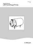
Instruction Manual
LKH Centrifugal Pump
ESE00698-EN13
Original manual
2009-12
Table of contents
The information herein is correct at the time of issue but may be subject to change without prior notice
1. EC Declaration of Conformity .......................................................................
5
2. Safety ....................................................................................................
2.1. Important information .............................................................................
2.2. Warning signs .....................................................................................
2.3. Safety precautions ................................................................................
6
6
6
7
3. Installation ..............................................................................................
3.1. Unpacking/Delivery ...............................................................................
3.2. Installation .........................................................................................
3.3. Pre-use check - Pump without/with impeller screw ...........................................
8
8
9
10
4. Operation ...............................................................................................
4.1. Operation/Control .................................................................................
4.2. Fault finding .......................................................................................
4.3. Recommended cleaning .........................................................................
11
11
13
14
5. Maintenance ...........................................................................................
5.1. General maintenance .............................................................................
5.2. Dismantling of pump/shaft seals ................................................................
5.3. Assembly of pump/single shaft seal ............................................................
5.4. Assembly of pump/flushed shaft seal ...........................................................
5.5. Assembly of pump/double mechanical shaft seal .............................................
5.6. Adjustment of shaft (LKH-5) .....................................................................
5.7. Adjustment of shaft (LKH-10 to -90) ............................................................
5.8. Cleaning Procedure ...............................................................................
15
15
17
19
21
23
25
27
29
6. Technical data .........................................................................................
6.1. Technical data .....................................................................................
6.2. Relubrication Intervals ............................................................................
6.3. Addendum .........................................................................................
30
30
31
32
7. Parts list and Service Kits ...........................................................................
7.1. LKH-5 Sanitary Version ..........................................................................
7.2. LKH-10, -15, -20, -25, -35, -40, -50, -60 Sanitary Version ..................................
7.3. LKH-70 - 90 Sanitary Version ...................................................................
7.4. LKH-5 Centrifugal Pump Single, Flushed and Double Mechanical Shaft Seal ..............
7.5. LKH-10 Centrifugal Pump Single, Flushed and Double Mechanical Shaft Seal ............
7.6. LKH-15 Centrifugal Pump Single, Flushed and Double Mechanical Shaft Seal ............
7.7. LKH-20 Centrifugal Pump Single, Flushed and Double Mechanical Shaft Seal ............
7.8. LKH-25 Centrifugal Pump Single, Flushed and Double Mechanical Shaft Seal ............
7.9. LKH-35 Centrifugal Pump Single, Flushed and Double Mechanical Shaft Seal ............
7.10. LKH-40 Centrifugal Pump Single, Flushed and Double Mechanical Shaft Seal ............
7.11. LKH-45 Centrifugal Pump Single, Flushed and Double Mechanical Shaft Seal ............
7.12. LKH-50 Centrifugal Pump Single, Flushed and Double Mechanical Shaft Seal ............
7.13. LKH-60 Centrifugal Pump Single, Flushed and Double Mechanical Shaft Seal ............
7.14. LKH 5-60 Centrifugal Pumps, Shaft Seals .....................................................
7.15. LKH-70 Centrifugal Pump Single, Flushed and Double Mechanical Shaft Seal ............
7.16. LKH-75 Centrifugal Pump Single, Flushed and Double Mechanical Shaft Seal ............
7.17. LKH-80 Centrifugal Pump Single, Flushed and Double Mechanical Shaft Seal ............
7.18. LKH-85 Centrifugal Pump Single, Flushed and Double Mechanical Shaft Seal ............
33
33
34
35
36
38
40
42
44
46
48
50
52
54
56
58
60
62
64
3
Table of contents
The information herein is correct at the time of issue but may be subject to change without prior notice
7.19. LKH-90 Centrifugal Pump Single, Flushed and Double Mechanical Shaft Seal ............
7.20. LKH-70, LKH-75, LKH-80, LKH-85 and LKH-90 Centrifugal Pump, Shaft Seal ...........
4
66
68
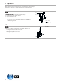
1 EC Declaration of Conformity
The designated company
Alfa Laval
Company Name
Albuen 31, DK-6000 Kolding, Denmark
Address
+45 79 32 22 00
Phone No.
hereby declare that
Pump
LKH
Denomination
Type
Year
is in conformity with the following directives with amendments:
- Low Voltage Directive 2006/95/EC
- EMC Directive 2004/108/EC
- Machinery Directive 2006/42/EC
The technical construction file is retained at the above address
Manager, Product Center Fluid Handling
Bjarne Søndergaard
Title
Name
Alfa Laval Kolding
Company
Signature
Designation
5
2 Safety
Unsafe practices and other important information are emphasized in this manual.
Warnings are emphasized by means of special signs.
Always read the manual before using the pump!
2.1
Important information
WARNING
Indicates that special procedures must be followed to avoid severe personal injury.
CAUTION
Indicates that special procedures must be followed to avoid damage to the pump.
NOTE
Indicates important information to simplify or clarify procedures.
2.2
Warning signs
General warning:
Dangerous electrical voltage:
Caustic agents:
Recycling information.
• Unpacking
-
Packing material consists of wood, plastics, cardboard boxes and in some cases metal straps.
Wood and cardboard boxes can be reused, recycled or used for energy recovery.
Plastics should be recycled or burnt at a licensed waste incineration plant.
Metal straps should be sent for material recycling.
• Maintenance
-
During maintenance oil and wear parts in the machine are replaced.
All metal parts should be sent for material recycling.
Worn out or defective electronic parts should be sent to a licensed handler for material recycling.
Oil and all non metal wear parts must be taken care of in agreement with local regulations.
• Scrapping
-
6
At end of use, the equipment shall be recycled according to relevant, local regulations. Beside the equipment itself, any
hazardous residues from the process liquid must be considered and dealt with in a proper manner. When in doubt, or in the
absence of local regulations, please contact the local Alfa Laval sales company.
2 Safety
All warnings in the manual are summarized on this page.
Pay special attention to the instructions below so that severe personal injury and/or damage to the pump are avoided.
2.3
Safety precautions
Installation:
Always read the technical data thoroughly. (See chapter 6 Technical data)
Always use a lifting crane when handling the pump.
Pump without impeller screw:
Always remove the impeller before checking the direction of rotation.
Never start the pump if the impeller is fitted and the pump casing is removed.
Pump with Impeller screw:
Never start in the wrong direction of rotation with liquid in the pump.
Always have the pump electrically connected by authorized personnel.
Always have the pump electrically connected by authorized personnel. (See the motor instruction)
Operation:
Always read the technical data thoroughly. (See chapter 6 Technical data)
Never run the pump when partially installed or not completely assembled
Necessary precautions must be taken if leakage occurs as this can lead to hazardous situations
Never touch the pump or the pipelines when pumping hot liquids or when sterilising.
Never run the pump with both the suction side and the pressure side blocked.
Always handle lye and acid with great care.
Maintenance:
Always read the technical data thoroughly. (See chapter 6 Technical data)
Never service the pump when it is hot.
The pump and the pipelines must n ever be pressurised when the pump is serviced.
Motors with grease nipples:
Remember lubrication according to information plate/label on the motor.
Always disconnect the power supply when servicing the pump.
Transportation:
Transportation of the pump or the pump unit:
Never lift or elevate in any way other than described in this manual
Always drain the pump head and accessories of any liquid
Always ensure that no leakage of lubricants can occur
Always transport the pump in it’s upright position
Always ensure that the unit is securely fixed during transportation
Always use original packaging or similar during transportation
7
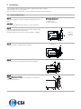
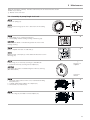
3 Installation
The instruction manual is part of the delivery. Study the instructions carefully.
The large pump sizes are very heavy.
Alfa Laval therefore recommends the use of a lifting crane when handling the pump.
3.1
Unpacking/Delivery
Step 1
Always use a lifting crane when handling the pump (see technical
data).
Check the delivery for:
1. Complete pump.
2. Delivery note.
3. Motor instructions.
CAUTION
Alfa Laval cannot be held responsible for incorrect unpacking.
Step 2
Remove possible packing materials from the inlet and the outlet.
Avoid damaging the inlet and the outlet.
Avoid damaging the connections for flushing liquid, if supplied.
Remove
packing
materials!
TD 200-120_1
Caution!
Step 3
Inspect the pump for visible transport damages.
Inspection!
TD 200-120_1
Step 4
Always remove the shroud, if fitted, before lifting the pump.
Step 5
ONLY LKH-85 and LKH-90
Do N OT use eyebolt in casing to lift the pump. The eyebolt is
only for casing removal.
8
Remove the shroud before lifting!
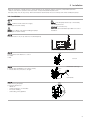
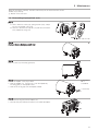
3 Installation
Study the instructions carefully and pay special attention to the warnings! Always check the pump before operation.
- See pre-use check in section 3.3 Pre-use check - Pump without/with impeller screw.
The large pump sizes are very heavy. Alfa Laval therefore recommends the use of a lifting crane when handling the pump.
3.2
Installation
Step 1
Always read the technical data thoroughly.
(See chaper 6 Technical data)
Always use a lifting crane when handling the pump.
(See chaper 6 Technical data)
Always have the pump electrically connected by
authorized personnel.
(see the motor instructions).
CAUTION
Alfa Laval cannot be held responsible for incorrect
installation.
Step 2
Ensure at least 0.5 m (1.6 ft) clearance around the pump.
Step 3
Check that the flow direction is correct.
O: Outlet
I: Inlet
Correct!
S tep 4
1. Ensure that the pipelines are routed correctly.
2. Ensure that the connections are tight.
Remember seal rings!
Few bends
Correct!
S tep 5
Avoid stressing the pump.
Pay special attention to:
- Vibrations.
- Thermal expansion of the tubes.
- Excessive welding.
- Overloading of the pipelines.
9
3 Installation
Study the instructions carefully and pay special attention to the warnings!
LKH-5 to -60 is without impeller screw as standard but can be supplied with one.
Check the direction of rotation of the impeller before operation.
- See the indication label on the pump.
3.3
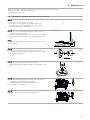
Pre-use check - Pump without/with impeller screw
Step 1
Always remove the impeller before checking the direction of
rotation.
Never start the pump if the impeller is fitted and the pump casing
is removed.
1.
A. LKH-5: Remove screws (56), spring washers (56a), clamps
(55+55a) and pump casing (29).
B. LKH-10 to -90: Remove cap nuts (24), washers (24a) and
pump casing (29).
2. Remove impeller (27) (see also instruction in section 5.3
Assembly of pump/single shaft seal).
S tep 2
1. Start and stop the motor momentarily.
2. Ensure that the direction of rotation of the stub shaft (7) is
anticlockwise as viewed from the inlet side.
See the indication label!
Correct!
Stub shaft
Step 3
Fit and tighten impeller (27).
S tep 4
1. Fit pump casing (29).
2.
A. LKH-5: Fit clamps (55+55a), spring washers (56a) and
tighten screws (56)
B. LKH-10 to -90: Fit washers (24a) and tighten cap nuts (24),
according to torque values in chapter 6.3 Addendum
Step 1
Pump with impeller screw
Never start in the wrong direction of rotation with liquid in the
pump.
1. Start and stop the motor momentarily.
2. Ensure that the direction of rotation of the motor fan is
clockwise as viewed from the rear end of the motor.
10
See the indication label!
Correct
View from rear end of
motor
4 Operation
Study the instructions carefully and pay special attention to the warnings!
The pump is fitted with a warning label indicating correct throttling
4.1
Operation/Control
Step 1
Always read the technical data thoroughly.
See chapter 6 Technical data
CAUTION
Alfa Laval cannot be held responsible for incorrect
operation/control.
Step 2
Burning danger!
Never touch the pump or the pipelines when pumping hot liquids
or when sterilising.
Step 3
Explosion danger!
Never run the pump with both the suction side and the pressure
side blocked.
S tep 4
CAUTION
The shaft seal must not run dry.
Do not run dry!
See the warning
label!
Correct!
CAUTION
Never throttle the inlet side.
TD 200-129_1
Wrong
11
4 Operation
Study the instructions carefully and pay special attention to the warnings!
The pump is fitted with a warning label indicating correct throttling
Step 5
Flushed shaft seal:
1. Connect the inlet of the flushing liquid correctly.
2. Regulate the water supply correctly.
3. Observe the steam data.
For LKH-85: connect inlet/outlet of the flushing liquid directly
on the flushing housing.
Correct!
O
R 1/8” (BSP)
TD 200-130_1
Tmax = 100ºC
I
O: Free outlet
I: Inlet
S tep 6
Control:
Reduce the capacity and the power consumption by means of:
-
12
Throttling the pressure side of the pump.
Reducing the impeller diameter.
Reducing the speed of the motor.
Pmax = 1 bar
Throttling!
4 Operation
Pay attention to possible faults.
Study the instructions carefully.
4.2
Fault finding
NOTE!
Study the maintenance instructions carefully before replacing worn parts. - See section 5.1 General maintenance
Remedy
Problem
Cause/result
Overloaded motor
-
Pumping of viscous liquids
Pumping of liquids with high density
Low outlet pressure (counter pressure) Lamination of precipitates from the
liquid
Higher counter pressure (throttling)
Frequent cleaning
-
Low inlet pressure
High liquid temperature
-
Increase the inlet pressure
Reduce the liquid temperature
-
Reduce the pressure drop before the
pump
Reduce speed
Cavitation:
- Damage
- Pressure reduction (sometimes to
zero)
- Increasing of the noise level
Leaking shaft seal
Leaking seals
Larger motor or smaller impeller
-
Dry run (See 4.1 Operation/Control)
Replace:
All wearing parts (See 5.1 General
maintenance)
-
Incorrect rubber grade
If necessary:
- Change rubber grade
-
Abrasive particles in the liquid
-
Incorrect rubber grade
Select stationary and rotating seal ring
in Silicon Carbide/Silicon Carbide
Replace with seals of a different rubber
grade
13
4 Operation
The pump is designed for cleaning in place (CIP). CIP = Cleaning In Place.
Study the instructions carefully and pay special attention to the warnings!
NaOH = Caustic Soda.
HNO3 = Nitric acid.
4.3
Recommended cleaning
Step 1
Caustic danger!
Always handle lye and acid with great care.
Always use rubber gloves!
Step 2
Always use protective
goggles!
Burning danger!
Never touch the pump or the pipelines when sterilizing.
Step 3
Examples of cleaning agents: Use clean water, free from
chlorides.
1. 1% by weight NaOH at 70°C (158°F).
+ 100 l (26.4 gal)
1 kg (2.2 lb)
= Cleaning agent.
water
NaOH
2.2 l (0.6 gal)
33%NaOH
+
100 l (26.4 gal)
water
2. 0.5% by weight HNO3 at 70°C (158°F).
+ 100 l (26.4 gal)
0.7 l (0.2 gal)
water
53% HNO3
= Cleaning agent.
= Cleaning agent.
Step 4
1. Avoid excessive concentration of the cleaning agent
Dose gradually!
2. Adjust the cleaning flow to the process
Sterilization of milk/viscous liquids
Increase the cleaning flow!
Step 5
Always rinse!
Always rinse well with clean water after using a cleaning agent.
NOTE
The cleaning agents must be stored/disposed of in accordance
with current rules/directives.
14
Water
Cleaning agent
5 Maintenance
Maintain the pump carefully. Study the instructions carefully and pay special attention to the warnings!
Always keep spare shaft seals and rubber seals in stock.
See separate motor instructions.
Check the pump for smooth operation after service.
5.1
General maintenance
Step 1
Always read the technical data thoroughly.
(See chaper 6 Technical data)
Always disconnect the power supply when servicing the pump.
NOTE
All scrap must be stored/discharged in accordance with current
rules/directives.
Step 2
Burning danger!
Never service the pump when it is hot.
Step 3
Atmospherie pressure
required!
Never service the pump with pump and pipelines under pressure.
CAUTION
Fit the electrical connections correctly if they have been removed
from the motor during service.
(see 3.3 Pre-use check - Pump without/with impeller screw)
CAUTION
Pay special attention to the warnings!
Step 4
Recommended spare parts:
Service kits (see chapter 7 Parts list and Service Kits).
Order Service Kits from Service kits list (see chapter 7 Parts list
and Service Kits).
Ordering spare parts
Contact the Sales Department.
15
5 Maintenance
Maintain the pump carefully. Study the instructions carefully and pay special attention to the warnings!
Always keep spare shaft seals and rubber seals in stock.
See separate motor instructions.
Check the pump for smooth operation after service.
Shaft seal
Preventive maintenance
-
-
Replace when replacing the
shaft seal
Replace when replacing the
Regular inspection for
leakage and smooth
shaft seal
operation
Keep a record of the pump
Use the statistics for
planning of inspections
Replace after leakage:
Complete shaft seal
Lubrication
Motor bearings
Replace when replacing the
R eplace after 12 months:
(one-shift) Complete shaft seal shaft seal
Maintenance after leakage
Replace at the end of the
(leakage normally starts slowly) day: Complete shaft seal
Planned maintenance
Rubber seals
Before fitting
Lubricate the O-rings with
silicone grease or silicone oil
Before fitting
Silicone grease or silicone oil
Yearly inspection is
recommended
- Replace complete bearing
if worn
- Ensure that the bearing is
axially locked (See motor
instructions)
See section 6.2 Relubrication
Intervals
Pre-use check
CAUTION!
Fit the electrical connections correctly if they have been removed from the motor during service. (See 3.3 Pre-use check Pump without/with impeller screw).
Pay special attention to warnings!
1. Start and stop the motor momentarily
2. Ensure that the pump operates smoothly.
16
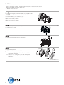
5 Maintenance
Study the instructions carefully. The items refer to the parts list and service kits section.
Handle scrap correctly.
: Relates to the shaft seal.
5.2
Dismantling of pump/shaft seals
Step 1
1.
A. LKH-5: Remove screws (56), spring washers (56a), clamps
(55+55a) and pump casing (29).
B. LKH-10 to 90: Unscrew cap nuts (24) and remove washers
(24a) and pump casing (29).
LKH-85 and LKH-90
S tep 2
Flushed / Double Mechanical shaft seal:
Unscrew tubes (42) using a spanner.
S tep 3
Remove screw (23) and safety guard (22).
Step 4
1. Remove impeller screw (36), if fitted.
2. Remove impeller (27). If necessary, loosen the impeller by
knocking gently on the impeller vanes.
3. Remove the O-ring (38) from the impeller, if fitted.
Counterhold
with a
screwdriver!
If necessary!
S tep 5
1. Pull off the O-ring (26) from back plate (25).
2. Unscrew nuts (20) and remove washers (21) and the back plate.
17
5 Maintenance
Study the instructions carefully. The items refer to the parts list and service kits section.
Handle scrap correctly.
: Relates to the shaft seal.
Step 6
1. Remove the stationary seal ring (11).
2. Remove the O-ring (12) from back plate (25).
Use the tool
supplied
Left hand
thread!
TD 200-462
S tep 7
Flushed shaft seal:
1. Remove screws (41) and seal housing (40).
2. Pull out lip seal (43) from the seal housing.
TD 200-390_1
Step 8
Double mechanical shaft seal:
1. Remove screws (41) and seal housing (40a).
2. Remove rotating seal rings (14) and drive ring (52) from spring
(13).
3. Remove O-rings (15) from rotating seal rings (14).
4. LKH-70 to 90: Remove cups (54) from rotating seal rings.
S tep 9
Double mechanical shaft seal:
1. Remove stationary seal ring (51) from seal housing (40a).
2. Remove O-ring (50) from stationary seal ring (51).
3. Remove O-ring (44) from seal housing (40a).
TD 200-391_1
Step 10
1. Remove the complete shaft seal from stub shaft (7).
2. Remove spring (13) and rotating seal ring (14) from the drive
ring (10).
TD 234-021_1
18
5 Maintenance
Study the instructions carefully. The items refer to the parts list and service kits section.
Handle scrap correctly.
: Relates to the shaft seal.
5.3
Assembly of pump/single shaft seal
Step 1
1. Remove spring (13).
NOTE!
Make sure that O-ring (15) has max. clearance from the sealing
surface.
S tep 2
1. Refit spring (13) on rotating seal ring (14).
2. Fit the spring and the rotating seal ring on drive ring (10).
CAUTION
Ensure that the driver on the drive ring enters the notch in the
rotating seal ring.
TD 200-393_1
S tep 3
Fit the complete shaft seal on stub shaft (7).
NOTE!
Make sure that connex pin (8) on the stub shaft enters the notch in
drive ring (10).
Step 4
1. Fit O-ring (12) on stationary seal ring (11) and lubricate.
2. Screw the stationary seal ring into back plate (25).
Use the tool
supplied
CAUTION
Only tighten by hand to avoid deforming the stationary seal ring.
(Max 7Nm/5 lbf-ft)
TD 200-462
Left hand
thread!
S tep 5
1. Clean the sealing surfaces with contact cleaner before fitting
back plate (25).
2. Carefully guide the back plate onto adaptor (16).
3. Fit washers (21) and nuts (20).
TD 234-009_1
Step 6
Lubricate O-ring (26) and slide it onto back plate (25).
TD 234-026_1
19
5 Maintenance
Study the instructions carefully. The items refer to the parts list and service kits section.
Handle scrap correctly.
: Relates to the shaft seal.
Step 7
1. Lubricate O-ring (38) and fit it in impeller (37), if impeller screw
is used.
2. Lubricate impeller hub with silicone grease or oil.
3. Screw the impeller onto stub shaft (7).
4. Fit impeller screw (39) and tighten, if used.
Torque - 5-60 = 20 Nm (7.4 lbf-ft)
Torque - 70-90 = 50 Nm (37 lbf-ft)
S tep 8
Fit safety guards (22) and screw (23) and tighten.
Step 9
1.
A. LKH-5: Fit pump casing (29), clamps (55+55a), spring
washers (56a) and screws (56).
B. LKH-10 to-90: Fit pump casing (29), washers (24a) and
cap nuts (24).
2. Adjust pump casing to the right position.
3.
A. LKH-5: Tighten nuts (20) for back plate (25) and tighten
screws (56).
B. LKH-10 to -90: Tighten nuts (20) for back plate (25) and
tighten cap nuts (24), according to torque values in chapter
6.3 Addendum.
20
LKH-85 and LKH-90
5 Maintenance
Study the instructions carefully. The items refer to the parts list and service kits section.
Lubricate the rubber seals before fitting them.
: Relates to the shaft seal.
5.4
Assembly of pump/flushed shaft seal
Step 1
Flushed shaft seal :
LKH-5 to -60 use ø63mm tube
LKH-70 to -90 press in lip seal by hand
1. Fit lip seal (43) in seal housing (40).
2. Lubricate O-ring (44) and slide onto the seal housing (40).
3. Fit the seal housing on back plate (25) and tighten screws (41).
Use ø63 mm tube!
Step 2
1. Lubricate O-ring (45) and fit it in drive ring (10).
2. Fit spring (13) and rotating seal ring (14) on the drive ring.
CAUTION
Ensure that the driver on the drive ring enters the notch in the
rotating seal ring.
TD 200-393_1
S tep 3
Fit complete shaft seal on stub shaft (7) so that connex pin (8) on
the stub shaft enters the notch in drive ring (10).
Step 4
1. Carefully guide back plate (25) onto adaptor (16).
2. Fit washers (21) and nuts (20).
TD 234-027_1
Step 5
Lubricate O-ring (26) and slide it onto back plate (25).
TD 234-026_1
Step 6
1. Lubricate O-ring (38) and fit it in impeller (37), if impeller screw
is used.
2. Lubricate the impeller hub with silicone grease or oil.
3. Screw impeller (27) onto stub shaft (7).
4. Fit impeller screw (36) and tighten, if used.
Torque - 5-60 20 Nm (7.4 lbf-ft)
Torque - 70-90 50 Nm (37 lbf-ft)
21
5 Maintenance
Study the instructions carefully. The items refer to the parts list and service kits section.
Lubricate the rubber seals before fitting them.
: Relates to the shaft seal.
Step 7
1. Screw tubes (42) into seal housing (40).
2. Tighten with a spanner.
TD 234-017_1
Step 8
Fit safety guard (22) and screw (23) and tighten.
Step 9
1.
A. LKH-5: Fit pump casing (29), clamps (55+55a), spring
washers (56a) and screws (56).
B. LKH-10 to-90: Fit pump casing (29).
2. Tighten nuts (20) for back plate (25).
3.
A. LKH-5: Tighten nuts (20) for back plate (25) and tighten
screws (56).
B. LKH-10 to -90: Fit washers (24a) and cap nuts (24)
and tighten, according to torque values in chapter 6.3
Addendum.
22
LKH-85 and LKH-90
5 Maintenance
Study the instructions carefully. The items refer to the parts list and service kits section.
Lubricate the rubber seals before fitting them.
: Relates to the shaft seal.
5.5
Assembly of pump/double mechanical shaft seal
Step 1
1. Fit O-rings (15) in rotating seal rings (14).
2. LKH-70 to -90: Fit cups (54) on rotating seal rings (14).
3. Fit spring (13) on one of the rotating seal rings (14) and
place the drive ring (52) in between.
Step 2
1. LKH-70 to -90: Turn the drive ring (52) in order to place it
correctly on the pump shaft (7).
2. Fit the second rotating ring (14) on the other end of the spring.
3. Place the parts on the stationary seal ring fitted in back plate
(25).
Only LKH-70-90
NOTE
Ensure that both drive pins on the drive ring enters the notches in
rotating seal rings.
Step 3
1. Lubricate O-ring (44) and slide onto seal housing (40a).
2. Lubricate O-ring (50) and fit on stationary seal ring (51) and fit
this in the seal housing.
TD 200-447_1
S tep 4
1. Clean the sealing surfaces with contact cleaner.
2. Fit seal housing (40a) on the back plate (25) and tighten screws
(41).
S tep 5
1. To enable fitting back plate (25) with the shaft seal remove
connex pin (8) from stub shaft (7) (if fitted).
2. Carefully guide the back plate onto adaptor (16).
3. Fit washers (21) and nuts (20).
TD 234-027_1
Step 6
Lubricate O-ring (26) and slide it onto back plate (25).
TD 234-033_1
23
5 Maintenance
Study the instructions carefully. The items refer to the parts list and service kits section.
Lubricate the rubber seals before fitting them.
: Relates to the shaft seal.
Step 7
1. Lubricate O-ring (38) and fit it in impeller (37), if impeller screw
is used.
2. Lubricate the impeller hub with silicone grease or oil.
3. Screw impeller (27) onto stub shaft (7).
4. Fit impeller screw (36) and tighten, if used.
Torque - 5-60 20 Nm (7.4 lbf-ft)
Torque - 70-90 50 Nm (37 lbf-ft)
S tep 8
1. Screw tubes (42) into seal housing (40a).
2. Tighten with a spanner.
TD 234-017_1
Step 9
Fit safety guard (22) and screw (23) and tighten.
Step 10
1. Fit pump casing (29).
2. Tighten nuts (20) for back plate (25).
3.
A. LKH-5: Fit clamps (55+55a), spring washers (56a) and
screws (56) and tighten.
B. LKH-10 to -90: Fit washers (24a) and cap nuts (24)
and tighten, according to torque values in chapter 6.3
Addendum.
LKH-85 and LKH-90
24
5 Maintenance
Study the instructions carefully. The items refer to the parts list and service kits section.
Lubricate the rubber seals before fitting them.
: Relates to the shaft seal.
5.6
Adjustment of shaft (LKH-5)
Step 1
1. Loosen screws (6).
2. Pull off stub shaft (7).
See special cleaning procedure for tapped hole in stub shaft
page 29.
S tep 2
1. Push stub shaft (7) onto the motor shaft. Screws (4) must fit
in keyway on the motor shaft.
2. Check that the clearance between the end of the stub shaft
and the motor flange is 10-20 mm (0.39 - 0.78 inch).
10-20 mm
(0.39-0.78 inch)
S tep 3
1. Tighten screws (4) lightly and evenly.
2. Ensure that stub shaft (7) can be moved on the motor shaft.
S tep 4
1. F or double mechanical shaft seal: Fit drive ring (52) on stub
shaft (7).
2. Fit back plate (25), washers (21) and nuts (20) and tighten.
S tep 5
1. Fit impeller (27) on stub shaft (7).
2. Ensure that the clearance between the impeller and back plate
(25) is correct: 0.5 mm (0.02 inch) for LKH-5.
LKH-5 = 0.5 mm (0.02 inch)
25
5 Maintenance
Study the instructions carefully. The items refer to the parts list and service kits section.
Lubricate the rubber seals before fitting them.
: Relates to the shaft seal.
Step 6
Tighten screws (4) evenly to 18 Nm (13 lbf-ft).
26
5 Maintenance
Study the instructions carefully. The items refer to the parts list and service kits section.
Lubricate the rubber seals before fitting them.
: Relates to the shaft seal.
5.7
Adjustment of shaft (LKH-10 to -90)
Step 1
1. Loosen screws (6).
2. Pull off stub shaft (7) together with compression rings (5a,5b).
See special cleaning procedure for tapped hole in stub shaft
page 29.
S tep 2
1. Push stub shaft (7) together with compression rings (5a, 5b)
onto the motor shaft.
2. Check that the clearance between the end of the stub shaft
and the motor flange is 10-20 mm (0.39 - 0.78 inch).
10-20 mm
(0.39-0.78 inch)
Step 3
1. Tighten screws (6) lightly and evenly.
2. Ensure that stub shaft (7) can be moved on the motor shaft.
S tep 4
1. F or double mechanical shaft seal:
Fit drive ring (52) on stub shaft (7).
2. Fit back plate (25), washers (21) and nuts (20) and tighten.
Step 5
1. Fit impeller (27) on stub shaft (7).
2. Ensure that the clearance between the impeller and back plate
(25) is correct: 0.5 mm (0.02 inch) for LKH-10 to 60 and 1.0
mm (0.039 inch) for LKH-70 to -90.
NOTE! If pump has been ordered with increased clearence
between impeller and backplate this additional clearence must be
taken into account when adjusting the shaft.
LKH-10 to -60 = 0.5 mm (0.02 inch)
LKH-70 to -90 = 1.0 mm (0.039 inch)
27
5 Maintenance
Study the instructions carefully. The items refer to the parts list and service kits section.
Lubricate the rubber seals before fitting them.
: Relates to the shaft seal.
Step 6
1. Remove impeller (27), back plate (25) and drive ring (52).
2. Tighten screws (6) evenly to 15 Nm (11 lbf-ft).
28
Counterhold with a screwdriver
15Nm
(11 lbf-ft)
5 Maintenance
5.8
Cleaning Procedure
Cleaning Procedure for Soiled Impeller Screw Tapped Hole:
1. Remove stub shaft (7) per section 4 of Service manual.
2. Submerge and soak Stub Shaft for 5 minutes in COP tank with 2% caustic wash
3. Scrub the blind tapped impeller screw hole vigorously by plunging a clean 1/2” diameter sanitary bristle pipe brush in and out
of the hole for two minutes while submerged.
4. Soak Stub Shaft (7) in acid sanitizer for 5 minutes, then scrub blind tapped hole as described in step 3 above.
5. Rinse well with clean water and blow-dry blind tapped hole with clean air.
6. Swab test the inside of the tapped hole to determine cleanliness.
7. Should the swab test fail, repeat steps 2 thru 6 above until swab test is passed.
Should swab testing continue to fail, or time is of the essence, install a new (spare) Stub Shaft (7).
29
6 Technical data
It is important to observe the technical data during installation, operation and maintenance.
Inform the personnel about the technical data.
6.1
Technical data
Data
Max. inlet pressure
Temperature range
Noise level
LKH-5 :
LKH-10 to -80 (50 Hz):
LKH-85 and LKH-90 (50 Hz):
LKH-10 to -60 (60 Hz):
LKH-70, LKH-75, LKH-85, LKH-90 (60 Hz):
-10o C to +140o C (EPDM) (14 to 284oF )
60-80 dB (A)
600 kPa
1000 kPa
500 kPa
1000 kPa
500 kPa
(6
(10
(5
(10
(5
bar)
bar)
bar)
bar)
bar)
(87 psi )
(145 psi )
(72.5 psi)
(145 psi )
(72.5 psi )
Materials
Product wetted steel parts
Other steel parts
Finish
AISI 316L
AISI 304
Semi-bright
Product wetted seals
Other O-rings
Alternative seals
EPDM (standard)
EPDM
Nitrile (NBR), Fluorinated rubber (FPM) and FEP
Shaft seal
Seal types
Max. water pressure (flushed seal)
Water consumption (flushed seal)
Max. water pressure LKH-5 to -60 (DMS)
Max. water pressure LKH-70 to -90 (DMS)
Water consumption (double mechanical seal)
Material, stationary seal ring
Material, rotating seal ring
Material, O-rings
Alternative material, O-rings
External single, flushed or double mechanical seal
Normally atmospheric (max. 1 bar) (max. 14.5 psi )
0.25 - 0.5 l/min. (0.07-0.13 gl )
Normally atmospheric (max. 5 bar) (max. 72.5 psi )
Normally atmospheric (max. 3 bar) (max. 43.5 psi )
0.25-0.5 l/min. (0.07-0.13 gl )
Acid resistent steel with sealing surface of Silicon Carbide
Carbon (standard) or Silicon Carbide
EPDM (standard)
Nitrile (NBR), Fluorinated rubber (FPM) and FEP
Motor
Foot-flanged motor acc. to IEC metric standard 2 poles = 3000/3600 rpm. at 50/60 Hz IP55 (drain hole with labyrinth
plug), insulation class F
Motor sizes (kW), 50 Hz
Motor sizes (kW), 60 Hz
Motor sizes (hp), 60 Hz
0.75 - 1.1 - 1.5 - 2.2 - 3 - 4 - 5.5 - 7.5 - 11 - 15 -18.5 - 22 - 30 - 37 - 45 55 - 75 - 90 - 110 kW
0.9 - 1.3 - 1.75 - 2.5 - 3.5 - 4.6 - 6.4 - 8.6 - 12.5 -17 - 21 - 25 - 35 - 43 52 - 63 - 86 - 105 - 125 kW.
1.5 - 2.0 - 3.0 - 5.0 - 7.5 - 10.0 - 15.0 - 20.0 - 25.0 - 30.0 - 40.0 50.0 - 60.0 - 75.0 - 100.0 - 125.0 - 150.0 hp
Voltage and frequency
Voltage and frequency (standard)
For further information - see PD-sheet.
30
3~,
3~,
3~,
3~,
50 Hz, 220-240V¨/380-420VY 4 kW
60 Hz, 250-280V¨/440-480VY 4.6 kW
50 Hz, 380-420V¨/660-690VY 5.5 kW
60 Hz, 440-480V¨ 6.3 kW
6 Technical data
Relubrication interval 50 Hz (3000 rpm)/Relubrication interval 60 Hz (3600 rpm). (Vendor) quantity in D rive E nd/quantity in
Non D rive E nd.
6.2
Relubrication Intervals
The table is for 100°C internal bearing temperature.an increase in temperature of 15°C (ambient or internal in bearings), will
reduce the greasing interval and bearing lifetime by 50%. Lubrication interval for vertically mounted pumps is half the value
stated in the table.
Frame
Motor
LKH-5 - 90
LKHP-10 - 60
LKH-122/P
size
power
LKHI-10 - 60*
LKHI-10 - 60
LKH-123/P
LKH-110*
LKH-110
LKH-124/P
LKHSP
50/60 Hz
50/60 Hz
(kW)
LKH Ultra Pure
50/60 Hz
80
0.75
Permanently lubricated (ABB)
Not available
Not available
80
1.1
Permanently lubricated (ABB)
Not available
Not available
90
1.5
Permanently lubricated (ABB)
Permanently lubricated (ABB)
Not available
90
2.2
Permanently lubricated (ABB)
Permanently lubricated (ABB)
Not available
100
3.0
Permanently lubricated (ABB)
Not available
Not available
112
4.0
Permanently lubricated (ABB)
4300h/3300h
Not available
132
5.5
Permanently lubricated (ABB)
3600h/3000h
132
7.5
Permanently lubricated (ABB)
DE/NDE:10g (Brook, ABB)
Not available
DE/NDE:15g (Brook, ABB)
3600h/3000h
Not available
DE/NDE:15g (Brook, ABB)
160
11
Permanently lubricated (ABB)
3100h/2300h
Not available
DE/NDE:25g (Brook, ABB)
160
15
Permanently lubricated (ABB)
3100h/2300h
Not available
DE/NDE:25g (Brook, ABB)
160
18.5
Permanently lubricated (ABB)
3100h/2300h
Not available
DE/NDE:25g (Brook, ABB)
180
22
Permanently lubricated (ABB)
2600h/2000h
Not available
DE/NDE:30g (Brook, ABB)
200
30
200
37
200
45
250
55
250
75
Permanently lubricated (ABB)
4000h/2800h
4000h/2800h
4300h/3500h DE/NDE: 23g (Brook)
DE/NDE:45g (Brook, ABB)
DE/NDE:45g (Brook, ABB)
Permanently lubricated (ABB)
4000h/2800h
4000h/2800h
4300h/3500h DE/NDE: 23g (Brook)
DE/NDE:45g (Brook, ABB)
DE/NDE:45g (Brook, ABB)
Permanently lubricated (ABB)
4000h/2800h
4000h/2800h
4300h/3500h DE/NDE: 23g (Brook)
DE/NDE:45g (Brook, ABB)
DE/NDE:45g (Brook, ABB)
Permanently lubricated (ABB)
Not available
3500h/2500h
3950h/3200h DE/NDE: 26g (Brook)
Permanently lubricated (ABB)
DE/NDE:45g (Brook, ABB)
Not available
3950h/3200h DE/NDE: 26g (Brook)
3500h/2500h
DE/NDE.45g (Brook, ABB)
* inlet pressure < 10 bar (145 psi )
Recommended grease types:
- Mobilgrease HP
- ESSO Unirex N3
- Shell Lipex EP2
- SKF LGHT3
- Castrol LMX
31
6 Technical data
6.3
Addendum
Section 1
Tightening torques
Below table specifies the tightening torques for the screws, bolts and nuts in this pump.
Always use below torques if no other values are stated. This can be a matter of personal safety.
Tightening torgue
Size
M8
M10
M12
M14
Nm
20
40
67
110
Pump Type
LKH-5
LKH-10
LKH-15
LKH-20
LKH-25
LKH-35
LKH-40
LKH-45
LKH-50
LKH-60
LKH-70
LKH-75
LKH-85
LKH-90
Sound pressure level (dBA)
60
69
72
70
74
71
75
70
75
77
88
79
86
75
lbf-ft
14.8
29.5
49.0
81.0
Section 2
Noise
The noise measurements are carried out with original motor and shroud, approximately at the Best Efficiency Point (BEP) with
water at ambient temperature and at 50Hz.
Very often the noise level generated by the flow through the process system (eg. valves, pipes, tanks etc.) is much higher than
what is generated by the pump itself. Therefore it is important to consider the noise level from the total system and take the
necessary percussions with regards to personal safety if required.
32
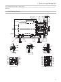
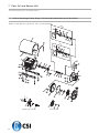
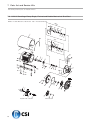
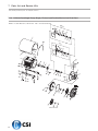
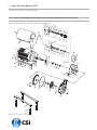
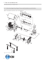
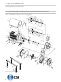
7 Parts list and Service Kits
The drawing shows LKH pump, sanitary version.
The items refer to the parts lists in the following sections 7.4 LKH-5 Centrifugal Pump Single, Flushed and Double Mechanical
Shaft Seal
7.1
LKH-5 Sanitary Version
Impeller screw
Flushed shaft seal
Ftting of legs
0.75-11 kW
Fitting of back plate
Double mechanical shaft seal
33
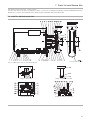
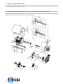
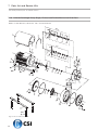
7 Parts list and Service Kits
The drawing shows LKH pump, sanitary version.
The items refer to the parts lists in the following sections 7.5 LKH-10 Centrifugal Pump Single, Flushed and Double Mechanical
Shaft Seal to 7.13 LKH-60 Centrifugal Pump Single, Flushed and Double Mechanical Shaft Seal
7.2
LKH-10, -15, -20, -25, -35, -40, -50, -60 Sanitary Version
Impeller screw
Flushed shaft seal
34
Only used for 0.75, 1.1 and 3 kW
Fitting of legs
Fitting of back plate
Double mechanical shaft seal
7 Parts list and Service Kits
The drawing shows LKH pump, sanitary version.
The items refer to the parts lists in the following sections 7.15 LKH-70 Centrifugal Pump Single, Flushed and Double Mechanical
Shaft Seal to 7.19 LKH-90 Centrifugal Pump Single, Flushed and Double Mechanical Shaft Seal
7.3
LKH-70 - 90 Sanitary Version
LKH-85 and LKH-90
LKH-75: USA version only, no shroud, US leg set.
Fitting of back plate
Fitting of legs 55 - 110 kW
Flushed shaft seal
Double mechanical shaft seal
35
7 Parts list and Service Kits
The drawing and the parts list include all items.
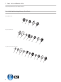
7.4
LKH-5 Centrifugal Pump Single, Flushed and Double Mechanical Shaft Seal
DMSS = Double Mechanical Shaft Seal. FSS = Flushed Shaft Seal
DM
SS
FSS
Alternatives
36
7 Parts list and Service Kits
The drawing and the parts list include all items.
Parts list
Pos.
1
2
2a
3
4
7
8
10
16
17
18
19
20
21
22
23
25
26
27
29
30a
30b
31
32
33
34
35
35a
36
37
38
39
40
40a
41
42
55
55a
56
56a
Service kits
Qty
۫{¨Ÿ
az
۫Ÿz
Denomination
1
1
1
4
2
1
1
1
1
4
4
4
2
2
1
1
1
1
Motor
Shroud
Edge list
Screw
Screw
Shaft and pin (pos.8)
Connex pin
Drive ring
Adaptor
Screw for adaptor
Nut for adaptor
Washer for adaptor
Nut
Washer
Safety guard
Screw for safety guard
Back plate
O-ring
1
1
1
1
4
4
4
4
4
4
1
1
1
4
1
1
2
2
1
1
2
2
Impeller
Pump casing
Support bar, right
Support bar, left
leg
Screw
Nut
Spring washer
Screw
Washer
Impeller screw
Impeller for impeller screw
O-ring
Nut
Seal housing
Seal housing
Screw for seal housing
Tube
Upper clamp
Lower clamp
Screw
Spring washer
Denomination
C /SIC
SIC/SIC
Service kit for single shaft seal
Service kit, EPDM (Std.) . . . . . . . . .
Service kit, NBR . . . . . . . . . . . . . . . . .
Service kit, FPM. . . . . . . . . . . . . . . . . .
Service kit, FEP . . . . . . . . . . . . . . . . . .
9611-92-2302
9611-92-2303
9611-92-2304
9611-92-2305
9611-92-2522
9611-92-2523
9611-92-2524
9611-92-2525
Service kit for single shaft seal and impeller screw
Service kit, EPDM (Std.) . . . . . . . . .
Service kit, NBR . . . . . . . . . . . . . . . . .
Service kit, FPM . . . . . . . . . . . . . . . . .
Service kit, FEP . . . . . . . . . . . . . . . . .
۫
9611-92-2306
9611-92-2307
۫ 9611-92-2308
۫ 9611-92-2309
۫
9611-92-2526
9611-92-2527
9611-92-2528
9611-92-2529
{
9611-92-2310
9611-92-2311
{ 9611-92-2312
{ 9611-92-2313
{
Service kit for flushed shaft seal
Service kit, EPDM (Std.) . . . . . . . . .
Service kit, NBR . . . . . . . . . . . . . . . . .
Service kit, FPM. . . . . . . . . . . . . . . . . .
Service kit, FEP . . . . . . . . . . . . . . . . . .
9611-92-2530
9611-92-2531
9611-92-2532
9611-92-2533
Service kit for flushed shaft seal and impeller screw
Service kit, EPDM (Std.) . . . . . . . . .
Service kit, NBR . . . . . . . . . . . . . . . . .
Service kit, FPM . . . . . . . . . . . . . . . . .
Service kit, FEP . . . . . . . . . . . . . . . . .
9611-92-2314
9611-92-2315
9611-92-2316
9611-92-2317
9611-92-2534
9611-92-2535
9611-92-2536
9611-92-2537
Service kit for double mechanical shaft seal C/SIC
Service kit, EPDM (Std.) . . . . . . . . .
Service kit, NBR . . . . . . . . . . . . . . . . .
Service kit, FPM. . . . . . . . . . . . . . . . . .
Service kit, FEP . . . . . . . . . . . . . . . . . .
9611-92-2318
9611-92-2319
¨ 9611-92-2320
¨ 9611-92-2321
9611-92-2538
9611-92-2539
a 9611-92-2540
a 9611-92-2541
¨
a
¨
a
Service kit for double mechanical shaft seal and impeller screw
Service kit, EPDM (Std.) . . . . . . . . .
Service kit, NBR . . . . . . . . . . . . . . . . .
Service kit, FPM. . . . . . . . . . . . . . . . . .
Service kit, FEP . . . . . . . . . . . . . . . . . .
9611-92-2322
9611-92-2323
Ÿ 9611-92-2324
Ÿ 9611-92-2325
9611-92-2542
9611-92-2543
z 9611-92-2544
z 9611-92-2545
Ÿ
z
Ÿ
z
Parts marked with ۫{¨Ÿaz are included in the service kits.
Recommended Spare Parts: Service kits.
Shaft seal: See page 56
Conversion kit, single to flushed shaft seal EPDM C/SIC 9611-92-2042 = Pos. 10+40b+41+42+43+44+45
Conversion kit, single to double mechanical shaft seal EPDM C/SIC 9611-92-2175 = Pos.13+ 14+15+40a+41+42+44+50+51+52
Conversion kit, flushed to double mechanical shaft seal EPDM C/SIC 9611-92-2176 = Pos.13+ 14+40a+50+51+52
900010/2
37
7 Parts list and Service Kits
The drawing and the parts list include all items.
7.5
LKH-10 Centrifugal Pump Single, Flushed and Double Mechanical Shaft Seal
DMSS = Double Mechanical Shaft Seal. FSS = Flushed Shaft Seal
DM
SS
FSS
Impeller with Inducer
38
Alternatives
7 Parts list and Service Kits
The drawing and the parts list include all items.
Parts list
Pos.
1
2a
2
3
5a
5b
6
6a
7
8
9
10
16
17
18
19
20
21
22
23
24
24a
25
26
27
28
29
30a
30b
31
32
33
34
35
35a
36
37
38
39
40
40a
41
42
57
Service kits
Qty
۫{¨Ÿ
az
۫Ÿz
Denomination
1
1
1
4
1
1
6
6
1
1
1
1
1
4
4
4
2
2
1
1
6
6
1
1
Motor
Edge list
Shroud complete
Screw
Compression ring with thread
Compression ring without thread
Screw
Washer
Shaft
Connex pin
Retaining ring
Drive ring
Adaptor
Screw for adaptor
Nut for adaptor
Washer for adaptor
Nut
Washer
Safety guard
Screw for safety guard
Cap nut
Washer
Back plate
O-ring
1
6
1
1
1
4
4
4
4
4
4
1
1
1
4
1
1
2
2
1
Impeller
Bolt
Pump casing
Support bar, right
Support bar, left
Leg
Screw
Nut
Spring washer
Screw
Washer
Impeller screw
Impeller for impeller screw
O-ring
Nut
Seal housing
Seal housing
Screw for seal housing
Tube
Inducer
Denomination
C /SIC
SIC/SIC
Service kit for single shaft seal
Service kit, EPDM (Std.) . . . . . . . . .
Service kit, NBR . . . . . . . . . . . . . . . . .
Service kit, FPM. . . . . . . . . . . . . . . . . .
Service kit, FEP . . . . . . . . . . . . . . . . . .
9611-92-2072
9611-92-2073
9611-92-2074
9611-92-2075
9611-92-2546
9611-92-2547
9611-92-2548
9611-92-2549
Service kit for single shaft seal and impeller screw
Service kit, EPDM (Std.) . . . . . . . . .
Service kit, NBR . . . . . . . . . . . . . . . . .
Service kit, FPM . . . . . . . . . . . . . . . . .
Service kit, FEP . . . . . . . . . . . . . . . . .
۫
9611-92-2114
9611-92-2115
۫ 9611-92-2116
۫ 9611-92-2117
۫
9611-92-2550
9611-92-2551
9611-92-2552
9611-92-2553
{
9611-92-2076
9611-92-2077
{ 9611-92-2078
{ 9611-92-2079
{
Service kit for flushed shaft seal
Service kit, EPDM (Std.) . . . . . . . . .
Service kit, NBR . . . . . . . . . . . . . . . . .
Service kit, FPM. . . . . . . . . . . . . . . . . .
Service kit, FEP . . . . . . . . . . . . . . . . . .
9611-92-2554
9611-92-2555
9611-92-2556
9611-92-2557
Service kit for flushed shaft seal and impeller screw
Service kit, EPDM (Std.) . . . . . . . . .
Service kit, NBR . . . . . . . . . . . . . . . . .
Service kit, FPM . . . . . . . . . . . . . . . . .
Service kit, FEP . . . . . . . . . . . . . . . . .
9611-92-2118
9611-92-2119
9611-92-2120
9611-92-2121
9611-92-2558
9611-92-2559
9611-92-2560
9611-92-2561
Service kit for double mechanical shaft seal
Service kit, EPDM (Std.) . . . . . . . . .
Service kit, NBR . . . . . . . . . . . . . . . . .
Service kit, FPM. . . . . . . . . . . . . . . . . .
Service kit, FEP . . . . . . . . . . . . . . . . . .
9611-92-2206
9611-92-2207
¨ 9611-92-2208
¨ 9611-92-2209
9611-92-2562
9611-92-2563
a 9611-92-2564
a 9611-92-2565
¨
a
¨
a
Service kit for double mechanical shaft seal and impeller screw
Service kit, EPDM (Std.) . . . . . . . . .
Service kit, NBR . . . . . . . . . . . . . . . . .
Service kit, FPM. . . . . . . . . . . . . . . . . .
Service kit, FEP . . . . . . . . . . . . . . . . . .
9611-92-2210
9611-92-2211
Ÿ 9611-92-2212
Ÿ 9611-92-2213
9611-92-2566
9611-92-2567
z 9611-92-2568
z 9611-92-2569
Ÿ
z
Ÿ
z
Parts marked with ۫{¨Ÿaz are included in the service kits. Recommended Spare Parts: Service kits. Shaft seal: See page 56
Conversion kit, single to flushed shaft seal EPDM C/SIC 9611-92-2042 = Pos. 10+40+41+42+43+44+45
Conversion kit single to double mechanical shaft seal EPDM C/SIC 9611-92-2175 = Pos.13+ 14+15+40a+41+42+44+50+51+52
Conversion kit single to double mechanical shaft seal EPDM SIC/SIC 9611-92-2326 = Pos. 13+14+15+40a+41+42+44+50+51+52
Conversion kit, flushed to double mechanical shaft seal EPDM C/SIC 9611-92-2176 = Pos.13+ 14+40a+50+51+52
Replace to inducer (For pump with impellerscrew) please order pos. 7+57+38
Replace to inducer (For pump without impellerscrew) please order pos. 7+57+37+38
900009/3
39
7 Parts list and Service Kits
The drawing and the parts list include all items.
7.6
LKH-15 Centrifugal Pump Single, Flushed and Double Mechanical Shaft Seal
DMSS = Double Mechanical Shaft Seal. FSS = Flushed Shaft Seal
DM
SS
FSS
Impeller with Inducer
40
Alternatives
7 Parts list and Service Kits
The drawing and the parts list include all items.
Parts list
Pos.
1
2a
2
3
5a
5b
6a
6
7
8
10
16
17
18
19
20
21
22
23
24
24a
25
26
27
28
29
30a
30b
31
32
33
34
35
35a
36
37
38
39
40
40a
41
42
46
57
Service kits
Qty
۫{¨Ÿ
az
۫Ÿz
Denomination
1
1
1
4
1
1
6
6
1
1
1
1
4
4
4
2
2
1
1
6
6
1
1
Motor
Edge list
Shroud complete
Screw
Compression ring with thread
Compression ring without thread
Washer
Screw
Shaft
Connex pin
Drive ring
Adaptor
Screw for adaptor
Nut for adaptor
Washer for adaptor
Nut
Washer
Safety guard
Screw for safety guard
Cap nut
Washer
Back plate
O-ring
1
6
1
1
1
4
4
4
4
4
4
1
1
1
4
1
1
2
2
4
1
Impeller
Bolt
Pump casing
Support bar, right
Support bar, left
Leg
Screw
Nut
Spring washer
Screw
Washer
Impeller screw
Impeller for impeller screw
O-ring
Nut
Seal housing
Seal housing
Screw for seal housing
Tube
Distance sleeve
Inducer
Denomination
C /SIC
SIC/SIC
Service kit for single shaft seal
Service kit, EPDM (Std.) . . . . . . . . .
Service kit, NBR . . . . . . . . . . . . . . . . .
Service kit, FPM. . . . . . . . . . . . . . . . . .
Service kit, FEP . . . . . . . . . . . . . . . . . .
9611-92-2072
9611-92-2073
9611-92-2074
9611-92-2075
9611-92-2546
9611-92-2547
9611-92-2548
9611-92-2549
Service kit for single shaft seal and impeller screw
Service kit, EPDM (Std.) . . . . . . . . .
Service kit, NBR . . . . . . . . . . . . . . . . .
Service kit, FPM . . . . . . . . . . . . . . . . .
Service kit, FEP . . . . . . . . . . . . . . . . .
۫
9611-92-2114
9611-92-2115
۫ 9611-92-2116
۫ 9611-92-2117
۫
9611-92-2550
9611-92-2551
9611-92-2552
9611-92-2553
{
9611-92-2076
9611-92-2077
{ 9611-92-2078
{ 9611-92-2079
{
Service kit for flushed shaft seal
Service kit, EPDM (Std.) . . . . . . . . .
Service kit, NBR . . . . . . . . . . . . . . . . .
Service kit, FPM. . . . . . . . . . . . . . . . . .
Service kit, FEP . . . . . . . . . . . . . . . . . .
9611-92-2554
9611-92-2555
9611-92-2556
9611-92-2557
Service kit for flushed shaft seal and impeller screw
Service kit, EPDM (Std.) . . . . . . . . .
Service kit, NBR . . . . . . . . . . . . . . . . .
Service kit, FPM . . . . . . . . . . . . . . . . .
Service kit, FEP . . . . . . . . . . . . . . . . .
9611-92-2118
9611-92-2119
9611-92-2120
9611-92-2121
9611-92-2558
9611-92-2559
9611-92-2560
9611-92-2561
Service kit for double mechanical shaft seal
Service kit, EPDM (Std.) . . . . . . . . .
Service kit, NBR . . . . . . . . . . . . . . . . .
Service kit, FPM. . . . . . . . . . . . . . . . . .
Service kit, FEP . . . . . . . . . . . . . . . . . .
9611-92-2206
9611-92-2207
¨ 9611-92-2208
¨ 9611-92-2209
9611-92-2562
9611-92-2563
a 9611-92-2564
a 9611-92-2565
¨
a
¨
a
Service kit for double mechanical shaft seal and impeller screw
Service kit, EPDM (Std.) . . . . . . . . .
Service kit, NBR . . . . . . . . . . . . . . . . .
Service kit, FPM. . . . . . . . . . . . . . . . . .
Service kit, FEP . . . . . . . . . . . . . . . . . .
9611-92-2210
9611-92-2211
Ÿ 9611-92-2212
Ÿ 9611-92-2213
9611-92-2566
9611-92-2567
z 9611-92-2568
z 9611-92-2569
Ÿ
z
Ÿ
z
Parts marked with ۫{¨Ÿaz are included in the service kits.
Recommended Spare Parts: Service kits.
Shaft seal: See page 56
Conversion kit, single to flushed shaft seal EPDM C/SIC 9611-92-2042 = Pos. 10+40+41+42+43+44+45
Conversion kit single to double mechanical shaft seal EPDM C/SIC 9611-92-2175 = Pos.13+ 14+15+40a+41+42+44+50+51+52
Conversion kit single to double mechanical shaft seal EPDM SIC/SIC 9611-92-2326 = Pos.13+ 14+15+40a+41+42+44+50+51+52
Conversion kit, flushed to double mechanical shaft seal EPDM C/SIC 9611-92-2176 = Pos. 13+14+40a+50+51+52
Replace to inducer (for pump with impellerscrew) please order pos. 7+57+38
Replace to inducer (for pump without impellerscrew) please order pos. 7+57+37+38
900010/2
41
7 Parts list and Service Kits
The drawing and the parts list include all items.
7.7
LKH-20 Centrifugal Pump Single, Flushed and Double Mechanical Shaft Seal
DMSS = Double Mechanical Shaft Seal. FSS = Flushed Shaft Seal
DM
SS
FSS
Impeller with Inducer
42
Alternatives
7 Parts list and Service Kits
The drawing and the parts list include all items.
Parts list
Pos.
1
2
2a
3
5a
5b
6
6a
7
8
9
10
16
17
18
19
20
21
22
23
24
24a
25
26
27
28
29
30a
30b
31
32
33
34
35
35a
36
37
38
39
40
40a
41
42
46
57
Service kits
Qty
۫{¨Ÿ
az
۫Ÿz
Denomination
1
1
1
4
1
1
6
6
1
1
1
1
1
4
4
4
2
2
1
1
6
6
1
1
Motor
Shroud complete
Edge list
Screw
Compression ring with thread
Compression ring without thread
Screw
Washer
Shaft
Connex pin
Retaining ring
Drive ring
Adaptor
Screw for adaptor
Nut for adaptor
Washer for adaptor
Nut
Washer
Safety guard
Screw for safety guard
Cap nut
Washer
Back plate
O-ring
1
6
1
1
1
4
4
4
4
4
4
1
1
1
4
1
1
2
2
4
1
Impeller
Bolt
Pump casing
Support bar, right
Support bar, left
Leg
Screw
Nut
Spring washer
Screw
Washer
Impeller screw
Impeller for impeller screw
O-ring EPDM
Nut
Seal housing
Seal housing
Screw for seal housing
Tube
Distance sleeve
Inducer
Denomination
C /SiC
SiC/SiC
Service kit for single shaft seal
Service kit, EPDM (Std.) . . . . . . . . .
Service kit, NBR . . . . . . . . . . . . . . . . .
Service kit, FPM. . . . . . . . . . . . . . . . . .
Service kit, FEP . . . . . . . . . . . . . . . . . .
9611-92-2080
9611-92-2081
9611-92-2082
9611-92-2083
9611-92-2570
9611-92-2571
9611-92-2572
9611-92-2573
Service kit for single shaft seal and impeller screw
Service kit, EPDM (Std.) . . . . . . . . .
Service kit, NBR . . . . . . . . . . . . . . . . .
Service kit, FPM . . . . . . . . . . . . . . . . .
Service kit, FEP . . . . . . . . . . . . . . . . .
۫
9611-92-2122
9611-92-2123
۫ 9611-92-2124
۫ 9611-92-2125
۫
9611-92-2574
9611-92-2575
9611-92-2576
9611-92-2577
{
9611-92-2084
9611-92-2085
{ 9611-92-2086
{ 9611-92-2087
{
Service kit for flushed shaft seal
Service kit, EPDM (Std.) . . . . . . . . .
Service kit, NBR . . . . . . . . . . . . . . . . .
Service kit, FPM. . . . . . . . . . . . . . . . . .
Service kit, FEP . . . . . . . . . . . . . . . . . .
9611-92-2578
9611-92-2579
9611-92-2580
9611-92-2581
Service kit for flushed shaft seal and impeller screw
Service kit, EPDM (Std.) . . . . . . . . .
Service kit, NBR . . . . . . . . . . . . . . . . .
Service kit, FPM . . . . . . . . . . . . . . . . .
Service kit, FEP . . . . . . . . . . . . . . . . .
9611-92-2126
9611-92-2127
9611-92-2128
9611-92-2129
9611-92-2582
9611-92-2583
9611-92-2584
9611-92-2585
Service kit for double mechanical shaft seal
Service kit, EPDM (Std.) . . . . . . . . .
Service kit, NBR . . . . . . . . . . . . . . . . .
Service kit, FPM. . . . . . . . . . . . . . . . . .
Service kit, FEP . . . . . . . . . . . . . . . . . .
9611-92-2214
9611-92-2215
¨ 9611-92-2216
¨ 9611-92-2217
9611-92-2586
9611-92-2587
a 9611-92-2588
a 9611-92-2589
¨
a
¨
a
Service kit for double mechanical shaft seal and impeller screw
Service kit, EPDM (Std.) . . . . . . . . .
Service kit, NBR . . . . . . . . . . . . . . . . .
Service kit, FPM. . . . . . . . . . . . . . . . . .
Service kit, FEP . . . . . . . . . . . . . . . . . .
9611-92-2218
9611-92-2219
Ÿ 9611-92-2220
Ÿ 9611-92-2221
9611-92-2590
9611-92-2591
z 9611-92-2592
z 9611-92-2593
Ÿ
z
Ÿ
z
Parts marked with ۫{¨Ÿaz are included in the service kits.
Recommended Spare Parts: Service kits.
Shaft seal: See page 56
Conversion kit, single to flushed shaft seal EPDM C/SIC 9611-92-2042 = Pos. 10+40+41+42+43+44+45
Conversion kit single to double mechanical shaft seal EPDM C/SIC 9611-92-2175 = Pos. 13+14+15+40a+41+42+44+50+51+52
Conversion kit single to double mechanical shaft seal EPDM SIC/SIC 9611-92-2326 = Pos.13+ 14+15+40a+41+42+44+50+51+52
Conversion kit, flushed to double mechanical shaft seal EPDM C/SIC 9611-92-2176 = Pos.13+ 14+40a+50+51+52
Replace to inducer (For pump with impeller screw) please order pos. 7+57+38
Replace to inducer (For pump without impeller screw) please order pos. 7+57+37+38.
900011/2
43
7 Parts list and Service Kits
The drawing and the parts list include all items.
7.8
LKH-25 Centrifugal Pump Single, Flushed and Double Mechanical Shaft Seal
DMSS = Double Mechanical Shaft Seal. FSS = Flushed Shaft Seal
DM
SS
FSS
Impeller with Inducer
44
Alternatives
7 Parts list and Service Kits
The drawing and the parts list include all items.
Parts list
Pos.
1
2
2a
3
5a
5b
6
6a
7
8
10
16
17
18
19
20
21
22
23
24
24a
25
26
27
28
29
30a
30b
31
32
33
34
35
35a
36
37
38
40
40a
41
42
46
57
Service kits
Qty
۫{¨Ÿ
az
۫Ÿz
Denomination
1
1
1
4
1
1
6
6
1
1
1
1
4
4
4
2
2
1
1
6
6
1
1
Motor
Shroud complete
Edge list
Screw
Compression ring with thread
Compression ring without thread
Screw
Washer
Shaft
Connex pin
Drive ring
Adaptor
Screw for adaptor
Nut for adaptor
Washer for adaptor
Nut
Washer
Safety guard
Screw for safety guard
Cap nut
Washer
Back plate
O-ring
1
6
1
1
1
4
4
4
4
4
4
1
1
1
1
1
2
2
4
1
Impeller
Bolt
Pump casing
Support bar, right
Support bar, left
Leg
Screw
Nut
Spring washer
Screw
Washer
Impeller screw
Impeller for impeller screw
O-ring
Seal housing
Seal housing
Screw for seal housing
Tube
Distance sleeve
Inducer
Denomination
C /SIC
SIC/SIC
Service kit for single shaft seal
Service kit, EPDM (Std.) . . . . . . . . .
Service kit, NBR . . . . . . . . . . . . . . . . .
Service kit, FPM. . . . . . . . . . . . . . . . . .
Service kit, FEP . . . . . . . . . . . . . . . . . .
9611-92-2178
9611-92-2179
9611-92-2180
9611-92-2181
9611-92-2594
9611-92-2595
9611-92-2596
9611-92-2597
Service kit for single shaft seal and impeller screw
Service kit, EPDM (Std.) . . . . . . . . .
Service kit, NBR . . . . . . . . . . . . . . . . .
Service kit, FPM . . . . . . . . . . . . . . . . .
Service kit, FEP . . . . . . . . . . . . . . . . .
۫
9611-92-2182
9611-92-2183
۫ 9611-92-2184
۫ 9611-92-2185
۫
9611-92-2598
9611-92-2599
9611-92-2600
9611-92-2601
{
9611-92-2186
9611-92-2187
{ 9611-92-2188
{ 9611-92-2189
{
Service kit for flushed shaft seal
Service kit, EPDM (Std.) . . . . . . . . .
Service kit, NBR . . . . . . . . . . . . . . . . .
Service kit, FPM. . . . . . . . . . . . . . . . . .
Service kit, FEP . . . . . . . . . . . . . . . . . .
9611-92-2602
9611-92-2603
9611-92-2604
9611-92-2605
Service kit for flushed shaft seal and impeller screw
Service kit, EPDM (Std.) . . . . . . . . .
Service kit, NBR . . . . . . . . . . . . . . . . .
Service kit, FPM . . . . . . . . . . . . . . . . .
Service kit, FEP . . . . . . . . . . . . . . . . .
9611-92-2190
9611-92-2191
9611-92-2192
9611-92-2193
9611-92-2606
9611-92-2607
9611-92-2608
9611-92-2609
Service kit for double mechanical shaft seal
Service kit, EPDM (Std.) . . . . . . . . .
Service kit, NBR . . . . . . . . . . . . . . . . .
Service kit, FPM. . . . . . . . . . . . . . . . . .
Service kit, FEP . . . . . . . . . . . . . . . . . .
9611-92-2222
9611-92-2223
¨ 9611-92-2224
¨ 9611-92-2225
9611-92-2610
9611-92-2611
a 9611-92-2612
a 9611-92-2613
¨
a
¨
a
Service kit for double mechanical shaft seal and impeller screw
Service kit, EPDM (Std.) . . . . . . . . .
Service kit, NBR . . . . . . . . . . . . . . . . .
Service kit, FPM. . . . . . . . . . . . . . . . . .
Service kit, FEP . . . . . . . . . . . . . . . . . .
9611-92-2226
9611-92-2227
Ÿ 9611-92-2228
Ÿ 9611-92-2229
9611-92-2614
9611-92-2615
z 9611-92-2616
z 9611-92-2617
Ÿ
z
Ÿ
z
Parts marked with ۫{¨Ÿaz are included in the service kits.
Recommended Spare Parts: Service kits.
Shaft seal: See page 56
Conversion kit, single to flushed shaft seal EPDM C/SIC 9611-92-2891 = Pos. 10+40+41+42+43+44+45
Conversion kit single to double mechanical shaft seal EPDM C/SIC 9611-92-2175 = Pos. 13+14+15+40a+41+42+44+50+51+52
Conversion kit single to double mechanical shaft seal EPDM SIC/SIC 9611-92-2326 = Pos. 13+14+15+40a+41+42+44+50+51+52
Conversion kit, flushed to double mechanical shaft seal EPDM C/SIC 9611-92-2176 = Pos.13+ 14+40a+50+51+52
Replace to inducer (for pump with impellerscrew) please order pos. 7+57+38
Replace to inducer (for pump without impellerscrew) please order pos. 7+57+37+38
900012/3
45
7 Parts list and Service Kits
The drawing and the parts list include all items.
7.9
LKH-35 Centrifugal Pump Single, Flushed and Double Mechanical Shaft Seal
DMSS = Double Mechanical Shaft Seal. FSS = Flushed Shaft Seal
DM
SS
FSS
Impeller with Inducer
46
Alternatives
7 Parts list and Service Kits
The drawing and the parts list include all items.
Parts list
Pos.
1
2
2a
3
5a
5b
6
6a
7
8
10
16
17
18
19
20
21
22
23
24
24a
25
26
27
28
29
30a
30b
31
32
33
34
35
35a
36
37
38
40
40a
41
42
46
57
Service kits
Qty
۫{¨Ÿ
az
۫Ÿz
Denomination
1
1
1
4
1
1
6
6
1
1
1
1
4
4
4
2
2
1
1
6
6
1
1
Motor
Shroud complete
Edge list
Screw
Compression ring with thread
Compression ring without thread
Screw
Washer
Shaft
Connex pin
Drive ring
Adaptor
Screw for adaptor
Nut for adaptor
Washer for adaptor
Nut
Washer
Safety guard
Screw for safety guard
Cap nut
Washer
Back plate
O-ring
1
6
1
1
1
4
4
4
4
4
4
1
1
1
1
1
2
2
4
1
Impeller
Bolt
Pump casing
Support bar, right
Support bar, left
Leg
Screw
Nut
Spring washer
Screw
Washer
Impeller screw
Impeller for impeller screw
O-ring
Seal housing
Seal housing
Screw for seal housing
Tube
Distance sleeve
Inducer
Denomination
C /SIC
SIC/SIC
Service kit for single shaft seal
Service kit, EPDM (Std.) . . . . . . . . .
Service kit, NBR . . . . . . . . . . . . . . . . .
Service kit, FPM. . . . . . . . . . . . . . . . . .
Service kit, FEP . . . . . . . . . . . . . . . . . .
9611-92-2178
9611-92-2179
9611-92-2180
9611-92-2181
9611-92-2594
9611-92-2595
9611-92-2596
9611-92-2597
Service kit for single shaft seal and impeller screw
Service kit, EPDM (Std.) . . . . . . . . .
Service kit, NBR . . . . . . . . . . . . . . . . .
Service kit, FPM . . . . . . . . . . . . . . . . .
Service kit, FEP . . . . . . . . . . . . . . . . .
۫
9611-92-2182
9611-92-2183
۫ 9611-92-2184
۫ 9611-92-2185
۫
9611-92-2598
9611-92-2599
9611-92-2600
9611-92-2601
{
9611-92-2186
9611-92-2187
{ 9611-92-2188
{ 9611-92-2189
{
Service kit for flushed shaft seal
Service kit, EPDM (Std.) . . . . . . . . .
Service kit, NBR . . . . . . . . . . . . . . . . .
Service kit, FPM. . . . . . . . . . . . . . . . . .
Service kit, FEP . . . . . . . . . . . . . . . . . .
9611-92-2602
9611-92-2603
9611-92-2604
9611-92-2605
Service kit for flushed shaft seal and impeller screw
Service kit, EPDM (Std.) . . . . . . . . .
Service kit, NBR . . . . . . . . . . . . . . . . .
Service kit, FPM . . . . . . . . . . . . . . . . .
Service kit, FEP . . . . . . . . . . . . . . . . .
9611-92-2190
9611-92-2191
9611-92-2192
9611-92-2193
9611-92-2606
9611-92-2607
9611-92-2608
9611-92-2609
Service kit for double mechanical shaft seal
Service kit, EPDM (Std.) . . . . . . . . .
Service kit, NBR . . . . . . . . . . . . . . . . .
Service kit, FPM. . . . . . . . . . . . . . . . . .
Service kit, FEP . . . . . . . . . . . . . . . . . .
9611-92-2222
9611-92-2223
¨ 9611-92-2224
¨ 9611-92-2225
9611-92-2610
9611-92-2611
a 9611-92-2612
a 9611-92-2613
¨
a
¨
a
Service kit for double mechanical shaft seal and impeller screw
Service kit, EPDM (Std.) . . . . . . . . .
Service kit, NBR . . . . . . . . . . . . . . . . .
Service kit, FPM. . . . . . . . . . . . . . . . . .
Service kit, FEP . . . . . . . . . . . . . . . . . .
9611-92-2226
9611-92-2227
Ÿ 9611-92-2228
Ÿ 9611-92-2229
9611-92-2614
9611-92-2615
z 9611-92-2616
z 9611-92-2617
Ÿ
z
Ÿ
z
Parts marked with ۫{¨Ÿaz are included in the service kits.
Recommended Spare Parts: Service kits.
Shaft seal: See page 56
Conversion kit, single to flushed shaft seal EPDM C/SIC 9611-92-2891 = Pos. 10+40+41+42+43+44+45
Conversion kit, single to double mechanical shaft seal EPDM C/SIC 9611-92-2175 = Pos. 13+14+15+40a+41+42+44+50+51+52
Conversion kit, single to double mechanical shaft seal EPDM SIC/SIC 9611-92-2326 = Pos. 13+14+15+40a+41+42+44+50+51+52
Conversion kit, flushed to double mechanical shaft seal EPDM C/SIC 9611-92-2176 = Pos. 13+14+40a+50+51+52
Replace to inducer (for pump with impellerscrew) please order pos. 7+57+38
Replace to inducer (for pump without impellerscrew) please order pos. 7+57+37+38
900014/3
47
7 Parts list and Service Kits
The drawing and the parts list include all items.
7.10
LKH-40 Centrifugal Pump Single, Flushed and Double Mechanical Shaft Seal
DMSS = Double Mechanical Shaft Seal. FSS = Flushed Shaft Seal
DM
SS
FSS
Impeller with Inducer
48
Alternatives
7 Parts list and Service Kits
The drawing and the parts list include all items.
Parts list
Pos.
1
2
2a
3
5a
5b
6
6a
7
8
10
16
17
18
19
20
21
22
23
24
24a
25
26
27
28
29
30a
30b
31
32
33
34
35
35a
36
37
38
40a
46
57
Service kits
Qty
۫{¨Ÿ
az
۫Ÿz
Denomination
1
1
1
4
1
1
6
6
1
1
1
1
4
4
4
2
2
1
1
6
6
1
1
Motor
Shroud
Edge list
Screw
Compression ring with thread
Compression ring without thread
Screw
Washer
Shaft
Connex pin
Drive ring
Adaptor
Screw for adaptor
Nut for adaptor
Washer for adaptor
Nut
Washer
Safety guard
Screw for safety guard
Cap nut
Washer
Backplate
O-ring
1
6
1
1
1
4
4
4
4
4
4
1
1
1
1
4
1
Impeller
Bolt
Pump casing
Support bar, right
Support bar, left
Leg
Screw
Nut
Spring washer
Screw
Washer
Impeller screw
Impeller for impeller screw
O-ring
Seal housing
Distance sleeve
Inducer
Denomination
C /SIC
SIC/SIC
Service kits for single shaft seal
Service kit, EPDM (Std.) . . . . . . . . .
Service kit, NBR . . . . . . . . . . . . . . . . .
Service kit, FPM. . . . . . . . . . . . . . . . . .
Service kit, FEP . . . . . . . . . . . . . . . . . .
9611-92-2088
9611-92-2089
9611-92-2090
9611-92-2091
9611-92-2619
9611-92-2620
9611-92-2621
9611-92-2622
Service kits for single shaft seal and impeller screw
Service kit, EPDM (Std.) . . . . . . . . .
Service kit, NBR . . . . . . . . . . . . . . . . .
Service kit, FPM . . . . . . . . . . . . . . . . .
Service kit, FEP . . . . . . . . . . . . . . . . .
9611-92-2130
9611-92-2131
۫ 9611-92-2132
۫ 9611-92-2133
9611-92-2623
9611-92-2624
9611-92-2625
9611-92-2626
۫
۫
Service kits for flushed shaft seal
Service kit, EPDM (Std.) . . . . . . . . .
Service kit, NBR . . . . . . . . . . . . . . . . .
Service kit, FPM. . . . . . . . . . . . . . . . . .
Service kit, FEP . . . . . . . . . . . . . . . . . .
9611-92-2092
9611-92-2093
{ 9611-92-2094
{ 9611-92-2095
9611-92-2627
9611-92-2628
9611-92-2629
9611-92-2630
{
{
Service kits for flushed shaft seal and impeller screw
Service kit, EPDM (Std.) . . . . . . . . .
Service kit, NBR . . . . . . . . . . . . . . . . .
Service kit, FPM . . . . . . . . . . . . . . . . .
Service kit, FEP . . . . . . . . . . . . . . . . .
9611-92-2134
9611-92-2135
9611-92-2136
9611-92-2137
9611-92-2631
9611-92-2632
9611-92-2633
9611-92-2634
Service kits for double mechanical shaft seal
Service kit, EPDM (Std.) . . . . . . . . .
Service kit, NBR . . . . . . . . . . . . . . . . .
Service kit, FPM. . . . . . . . . . . . . . . . . .
Service kit, FEP . . . . . . . . . . . . . . . . . .
9611-92-2230
9611-92-2231
¨ 9611-92-2232
¨ 9611-92-2233
9611-92-2635
9611-92-2636
a 9611-92-2637
a 9611-92-2638
¨
a
¨
a
Service kits for double mechanical shaft seal and impeller screw
Service kit, EPDM (Std.) . . . . . . . . .
Service kit, NBR . . . . . . . . . . . . . . . . .
Service kit, FPM. . . . . . . . . . . . . . . . . .
Service kit, FEP . . . . . . . . . . . . . . . . . .
9611-92-2234
9611-92-2235
Ÿ 9611-92-2236
Ÿ 9611-92-2237
9611-92-2639
9611-92-2640
z 9611-92-2641
z 9611-92-2642
Ÿ
z
Ÿ
z
Parts marked with ۫{¨Ÿaz are included in the service kits. Recommended Spare Parts: Service kits. Shaft seal: See page 56
Conversion kit, single to flushed shaft seal EPDM C/SIC 9611-92-2891 = Pos. 10+40+41+42+43+44+45
Conversion kit, single to double mechanical shaft seal EPDM C/SIC 9611-92-2175 = Pos. 13+14+15+40a+41+42+44+ 50 +51+52
Conversion kit, single to double mechanical shaft seal EPDM SIC/SIC 9611-92-2326 = Pos.13+ 14+15+40a+41+42+44+ 50 +51+52
Conversion kit, flushed to double mechanical shaft seal EPDM C/SIC 9611-92-2176 = Pos. 13+14+40a+50+51+52
Replace to inducer (for pump with impellerscrew ) please order pos. 7+57+38
Replace to inducer (for pump without impellerscrew ) please order pos. 7+57+37+38
900015/4
49
7 Parts list and Service Kits
The drawing and the parts list include all items.
7.11
LKH-45 Centrifugal Pump Single, Flushed and Double Mechanical Shaft Seal
DMSS = Double Mechanical Shaft Seal. FSS = Flushed Shaft Seal
DM
SS
FSS
Impeller with Inducer
50
Alternatives
7 Parts list and Service Kits
The drawing and the parts list include all items.
Parts list
Pos.
1
2
2a
3
5a
5b
6
6a
7
8
10
16
17
18
19
20
21
22
23
24
24a
25
26
27
28
29
30a
30b
31
32
33
34
35
35a
36
37
38
40
41
42
46
57
Service kits
Qty
۫{¨Ÿ
az
۫Ÿz
Denomination
1
1
1
4
1
1
6
6
1
1
1
1
4
4
4
2
2
1
1
6
6
1
1
Motor
Shroud complete
Edge list
Screw
Compression ring with thread
Compression ring without thread
Screw
washer
Shaft
Connex pin
Drive ring
Adapter
Screw for adapter
Nut for adapter
washer for adapter
Nut
washer
Safety guard
Screw for safety guard
Cap nut
washer
Back plate
O-ring
1
6
1
1
1
4
4
4
4
4
4
1
1
1
1
2
2
4
1
Impeller
Bolt
Pump casing
Support bar, right
Support bar, Left
Leg
Screw
Nut
Spring washer
Screw
washer
Impeller screw
Impeller for impeller screw
O-ring
Seal housing
Screw for seal housing
Tube
Distance sleeve
Inducer
Denomination
C /SIC
SIC/SIC
Service kit for single shaft seal
Service kit, EPDM (std) . . . . . . . . . .
Service kit, NBR . . . . . . . . . . . . . . . . .
Service kit, FPM. . . . . . . . . . . . . . . . . .
Service kit, FEP . . . . . . . . . . . . . . . . . .
9611-92-2178
9611-92-2179
9611-92-2180
9611-92-2181
9611-92-2594
9611-92-2595
9611-92-2596
9611-92-2597
Service kit for single shaft seal and impeller screw
Service kit, EPDM (std) . . . . . . . . . .
Service kit, NBR . . . . . . . . . . . . . . . . .
Service kit, FPM. . . . . . . . . . . . . . . . . .
Service kit, FPM. . . . . . . . . . . . . . . . . .
۫
9611-92-2182
9611-92-2179
۫ 9611-92-2180
۫ 9611-92-2181
۫
9611-92-2598
9611-92-2595
9611-92-2596
9611-92-2597
{
9611-92-2186
9611-92-2187
{ 9611-92-2188
{ 9611-92-2189
{
Service kit for flushed shaft seal
Service kit, EPDM (std) . . . . . . . . . .
Service kit, NBR . . . . . . . . . . . . . . . . .
Service kit, FPM. . . . . . . . . . . . . . . . . .
Service kit, FEP . . . . . . . . . . . . . . . . . .
9611-92-2602
9611-92-2603
9611-92-2604
9611-92-2605
Service kit for flushed shaft seal and impeller screw
Service kit, EPDM (std) . . . . . . . . . .
Service kit, NBR . . . . . . . . . . . . . . . . .
Service kit, FPM . . . . . . . . . . . . . . . . .
Service kit, FEP . . . . . . . . . . . . . . . . .
9611-92-2190
9611-92-2191
9611-92-2192
9611-92-2193
9611-92-2606
9611-92-2607
9611-92-2608
9611-92-2609
Service kit for double mechanical shaft seal
Service kit, EPDM (std) . . . . . . . . . .
Service kit, NBR . . . . . . . . . . . . . . . . .
Service kit, FPM. . . . . . . . . . . . . . . . . .
Service kit, FEP . . . . . . . . . . . . . . . . . .
9611-92-2222
9611-92-2223
¨ 9611-92-2224
¨ 9611-92-2225
9611-92-2610
9611-92-2611
a 9611-92-2612
a 9611-92-2613
¨
a
¨
a
Service kit for double mechanical shaft seal and impeller screw
Service kit, EPDM (std) . . . . . . . . . .
Service kit, NBR . . . . . . . . . . . . . . . . .
Service kit, FPM. . . . . . . . . . . . . . . . . .
Service kit, FEP . . . . . . . . . . . . . . . . . .
9611-92-2226
9611-92-2227
Ÿ 9611-92-2228
Ÿ 9611-92-2229
9611-92-2614
9611-92-2615
z 9611-92-2616
z 9611-92-2617
Ÿ
z
Ÿ
z
Parts marked with ۫{¨Ÿaz are included in the service kits.
Recommended Spare Parts: Service kits.
Shaft seal: See page 56
Conversion kit, single to flushed shaft seal EPDM C/SIC 9611-92-2891 = Pos. 10+40+41+42+43+44+45
Conversion kit, single to double mechanical shaft seal EPDM C/SIC 9611-92-2175 = Pos.13+ 14+15+40a+41+42+44+50+51+52
Conversion kit, single to double mechanical shaft seal EPDM SIC/SIC 9611-92-2326 = Pos. 13+14+15+40a+41+42+44+50+51+52
Conversion kit, flushed to double mechanical shaft seal EPDM C/SIC 9611-92-2176 = Pos. 13+14+40a+50+51+52
Replace to inducer (for pump with impellerscrew) please order pos. 7+57+38
Replace to inducer (for pump without impellerscrew) please order pos. 7+57+37+38
900016/3
51
7 Parts list and Service Kits
The drawing and the parts list include all items.
7.12
LKH-50 Centrifugal Pump Single, Flushed and Double Mechanical Shaft Seal
DMSS = Double Mechanical Shaft Seal. FSS = Flushed Shaft Seal
DM
SS
FSS
Impeller with Inducer
52
Alternatives
7 Parts list and Service Kits
The drawing and the parts list include all items.
Parts list
Pos.
Qty
1
2
2a
3
5a
5b
6
6a
7
8
10
16
17
18
19
20
21
22
23
24
24a
25
26
27
28
29
30a
30b
31
32
33
34
35
35a
36
37
38
40
40a
41
42
46
57
Service kits
۫{¨Ÿ
az
۫Ÿz
Denomination
1
1
1
1
1
1
4
1
1
6
6
1
1
1
1
4
4
4
2
2
1
1
6
6
1
1
Motor
Motor
Shroud
Shroud
Edge list
Edge list
Screw
Compression ring with thread
Compression ring without thread
Screw
Washer
Shaft
Connex pin
Drive ring
Adaptor
Screw for adaptor
Nut for adaptor
Washer for adaptor
Nut
Washer
Safety guard
Screw for safety guard
Cap nut
Washer
Back plate
O-ring
1
6
1
1
1
4
4
4
4
4
4
1
1
1
1
1
2
2
4
1
Impeller
Bolt
Pump casing
Support bar, right
Support bar, left
Leg
Screw
Nut
Spring washer
Screw
Washer
Impeller screw
Impeller for impeller screw
O-ring
Seal housing
Seal housing
Screw for seal housing
Tube
Distance
Inducer
Denomination
C /SIC
SIC/SIC
Service kit for single shaft seal
Service kit, EPDM (Std.) . . . . . . . . .
Service kit, NBR . . . . . . . . . . . . . . . . .
Service kit, FPM. . . . . . . . . . . . . . . . . .
Service kit, FEP . . . . . . . . . . . . . . . . . .
9611-92-2088
9611-92-2089
9611-92-2090
9611-92-2091
9611-92-2619
9611-92-2620
9611-92-2621
9611-92-2622
Service kit for single shaft seal and impeller screw
Service kit, EPDM (Std.) . . . . . . . . .
Service kit, NBR . . . . . . . . . . . . . . . . .
Service kit, FPM . . . . . . . . . . . . . . . . .
Service kit, FEP . . . . . . . . . . . . . . . . .
۫
9611-92-2130
9611-92-2131
۫ 9611-92-2132
۫ 9611-92-2133
۫
9611-92-2623
9611-92-2624
9611-92-2625
9611-92-2626
{
9611-92-2092
9611-92-2093
{ 9611-92-2094
{ 9611-92-2095
{
Service kit for flushed shaft seal
Service kit, EPDM (Std.) . . . . . . . . .
Service kit, NBR . . . . . . . . . . . . . . . . .
Service kit, FPM. . . . . . . . . . . . . . . . . .
Service kit, FEP . . . . . . . . . . . . . . . . . .
9611-92-2627
9611-92-2628
9611-92-2629
9611-92-2630
Service kit for flushed shaft seal and impeller screw
Service kit, EPDM (Std.) . . . . . . . . .
Service kit, NBR . . . . . . . . . . . . . . . . .
Service kit, FPM . . . . . . . . . . . . . . . . .
Service kit, FEP . . . . . . . . . . . . . . . . .
9611-92-2134
9611-92-2135
9611-92-2136
9611-92-2137
9611-92-2631
9611-92-2632
9611-92-2633
9611-92-2634
Service kit for double mechanical shaft seal
Service kit, EPDM (Std.) . . . . . . . . .
Service kit, NBR . . . . . . . . . . . . . . . . .
Service kit, FPM. . . . . . . . . . . . . . . . . .
Service kit, FEP . . . . . . . . . . . . . . . . . .
9611-92-2230
9611-92-2231
¨ 9611-92-2232
¨ 9611-92-2233
9611-92-2635
9611-92-2636
a 9611-92-2637
a 9611-92-2638
¨
a
¨
a
Service kit for double mechanical shaft seal and impeller screw
Service kit, EPDM (Std.) . . . . . . . . .
Service kit, NBR . . . . . . . . . . . . . . . . .
Service kit, FPM. . . . . . . . . . . . . . . . . .
Service kit, FEP . . . . . . . . . . . . . . . . . .
9611-92-2234
9611-92-2235
Ÿ 9611-92-2236
Ÿ 9611-92-2237
9611-92-2639
9611-92-2640
z 9611-92-2641
z 9611-92-2642
Ÿ
z
Ÿ
z
Parts marked with ۫{¨Ÿaz are included in the service kits. Recommended Spare Parts: Service kits. Shaft seal: See page 56
Conversion kit, single to flushed shaft seal EPDM C/SIC 9611-92-2891 = Pos. 10+40+41+42+43+44+45
Conversion kit, single to double mechanical shaft seal EPDM C/SIC 9611-92-2175 = Pos. 13+14+15+40a+41+42+44+50+51+52
Conversion kit, single to double mechanical shaft seal EPDM SIC/SIC 9611-92-2326 = Pos. 13+14+15+40a+41+42+44+50+51+52
Conversion kit, flushed to double mechanical shaft seal EPDM C/SIC 9611-92-2176 = Pos. 13+14+40a+50+51+52
Replace to inducer (for pump with impellerscrew) please order pos. 7+57+38
Replace to inducer (for pump without impellerscrew) please order pos. 7+57+37+38.
900017/5
53
7 Parts list and Service Kits
The drawing and the parts list include all items.
7.13
LKH-60 Centrifugal Pump Single, Flushed and Double Mechanical Shaft Seal
DMSS = Double Mechanical Shaft Seal. FSS = Flushed Shaft Seal
DM
S
S
FSS
Alternatives
54
7 Parts list and Service Kits
The drawing and the parts list include all items.
Parts list
Pos.
Qty
1
2a
2
3
5a
5b
6
6a
7
8
10
16
17
18
19
20
21
22
23
24
24a
25
26
27
28
29
30a
30b
31
32
33
34
35
35a
36
37
38
40
41
42
46
53
Service kits
۫{¨Ÿ
az
۫Ÿz
Denomination
1
1
1
1
1
1
4
1
1
6
6
1
1
1
1
4
4
4
2
2
1
1
6
6
1
1
Motor
Motor
Edge list
Edge list
Shroud
Shroud
Screw
Compression ring with thread
Compression ring without thread
Screw
Washer
Shaft
Connex pin
Drive ring
Adaptor
Screw for adaptor
Nut for adaptor
Washer for adaptor
Nut
Washer
Safety guard
Screw for safety guard
Cap nut
Spring washer
Back plate
O-ring
1
6
1
1
1
4
4
4
4
4
4
1
1
1
1
2
2
4
4
Impeller
Bolt
Pump casing
Support bar, right
Support bar, left
Leg
Screw
Nut
Spring washer
Screw
Washer
Impeller screw
Impeller for impeller screw
O-ring
Seal housing
Screw for seal housing
Tube
Distance sleeve
Pivot screw (30 kW only)
Denomination
C /SIC
SIC/SIC
Service kit for single shaft seal
Service kit, EPDM (Std.) . . . . . . . . .
Service kit, NBR . . . . . . . . . . . . . . . . .
Service kit, FPM. . . . . . . . . . . . . . . . . .
Service kit, FEP . . . . . . . . . . . . . . . . . .
9611-92-2088
9611-92-2089
9611-92-2090
9611-92-2091
9611-92-2619
9611-92-2620
9611-92-2621
9611-92-2622
Service kit for single shaft seal and impeller screw
Service kit, EPDM (Std.) . . . . . . . . .
Service kit, NBR . . . . . . . . . . . . . . . . .
Service kit, FPM . . . . . . . . . . . . . . . . .
Service kit, FEP . . . . . . . . . . . . . . . . .
۫
9611-92-2130
9611-92-2131
۫ 9611-92-2132
۫ 9611-92-2133
۫
9611-92-2623
9611-92-2624
9611-92-2625
9611-92-2626
{
9611-92-2092
9611-92-2093
{ 9611-92-2094
{ 9611-92-2095
{
Service kit for flushed shaft seal
Service kit, EPDM (Std.) . . . . . . . . .
Service kit, NBR . . . . . . . . . . . . . . . . .
Service kit, FPM. . . . . . . . . . . . . . . . . .
Service kit, FEP . . . . . . . . . . . . . . . . . .
9611-92-2627
9611-92-2628
9611-92-2629
9611-92-2630
Service kit for flushed shaft seal and impeller screw
Service kit, EPDM (Std.) . . . . . . . . .
Service kit, NBR . . . . . . . . . . . . . . . . .
Service kit, FPM . . . . . . . . . . . . . . . . .
Service kit, FEP . . . . . . . . . . . . . . . . .
9611-92-2134
9611-92-2135
9611-92-2136
9611-92-2137
9611-92-2631
9611-92-2632
9611-92-2633
9611-92-2634
Service kit for double mechanical shaft seal
Service kit, EPDM (Std.) . . . . . . . . .
Service kit, NBR . . . . . . . . . . . . . . . . .
Service kit, FPM. . . . . . . . . . . . . . . . . .
Service kit, FEP . . . . . . . . . . . . . . . . . .
9611-92-2230
9611-92-2231
¨ 9611-92-2232
¨ 9611-92-2233
9611-92-2635
9611-92-2636
a 9611-92-2637
a 9611-92-2638
¨
a
¨
a
Service kits
Denomination
C /SIC
SIC/SIC
Service kit for double mechanical shaft seal and impeller screw
Service kit, EPDM (Std.) . . . . . . . . .
Service kit, NBR . . . . . . . . . . . . . . . . .
Service kit, FPM. . . . . . . . . . . . . . . . . .
Service kit, FEP . . . . . . . . . . . . . . . . . .
9611-92-2234
9611-92-2235
Ÿ 9611-92-2236
Ÿ 9611-92-2237
9611-92-2639
9611-92-2640
z 9611-92-2641
z 9611-92-2642
Ÿ
z
Ÿ
z
Parts marked with ۫{¨Ÿaz are included in the service kits.
Recommended Spare Parts: Service kits.
Shaft seal: See page 56
Conversion kit, single to flushed shaft seal EPDM C/SIC 9611-92-2891 = Pos. 10+40+41+42+43+44+45
Conversion kit, single to double mechanical shaft seal EPDM C/SIC 9611-92-2175 = Pos. 13+14+15+40a+41+42+44+50+51+52
Conversion kit, single to double mechanical shaft seal EPDM SIC/SIC 9611-92-2326 = Pos. 13+14+15+40a+41+42+44+50+51+52
Conversion kit, flushed to double mechanical shaft seal EPDM C/SIC 9611-92-2176 = Pos. 13+14+40a+50+51+52
900018/7
55
7 Parts list and Service Kits
The drawing and the parts list include all items.
7.14
LKH 5-60 Centrifugal Pumps, Shaft Seals
Single Shaft Seal.
13
15
14
TD 200-372_1
12
11
Flushed Shaft Seal.
43
44
45
13
15
14
TD 200-373_1
12
11
Double Mechanical Shaft Seal
50
51
44
52
14
15
13
15
14
TD 200-374
12
11
56
7 Parts list and Service Kits
The drawing and the parts list include all items.
Parts list
Pos.
Qty
۫
{
Ÿa
¨z
11
12
13
14
15
43
44
45
50
51
52
1
1
1
1
2
1
2
1
1
1
1
1
1
Denomination
Complete shaft seal
Complete shaft seal
Complete shaft seal
Complete shaft seal
Complete shaft seal
Complete shaft seal
Stationary seal ring
O-ring
Spring
Rotating seal ring
Rotating seal ring, carbon
O-ring
O-ring
Lip seal
O-ring for seal housing
O-ring for drive ring
O-ring
Sec. stationary seal ring
Drive ring
57
7 Parts list and Service Kits
The drawing and the parts list include all items.
7.15
LKH-70 Centrifugal Pump Single, Flushed and Double Mechanical Shaft Seal
DMSS = Double Mechanical Shaft Seal. FSS = Flushed Shaft Seal
DM
SS
FSS
Legs for motor sizes 55-75 kW
58
7 Parts list and Service Kits
The drawing and the parts list include all items.
Parts list
Pos.
1
2
2a
3
5a
5b
6
6a
7
10
16
17
18
19
20
21
22
23
24
24a
25
26
28
29
30a
30b
31
32
33
34
35
35a
36
37
38
40
40a
41
42
46
47
48
49
53
Service kits
Qty
۫
۫
1
1
1
4
1
1
6
6
1
1
1
4
4
4
4
4
1
1
8
8
1
1
8
1
1
1
4
4
4
4
4
4
1
1
1
1
1
2
2
4
2
4
4
4
Denomination
Motor
Shroud
Edge list
Screw
Compression ring with thread
Compression ring without thread
Screw
Washer
Shaft
Drive ring
Adaptor
Screw for adaptor
Nut for adaptor
Washer for adaptor
Nut
Washer
Safety guard
Screw for safety guard
Cap nut
Spring washer
Back plate
O-ring
Pin bolt
Pump casing
Support bar, right
Support bar, left
Leg
Screw
Nut
Spring washer
Screw
Washer
Impeller screw
Impeller
O-ring
Seal housing
Seal housing
Screw for seal housing
Tube
Distance sleeve
Leg bracket
Nut for leg
Screw for leg
Pivot screw
Denomination
C /SIC
SIC/SIC
Service kit for single shaft seal
Service kit, EPDM (Std.) . . . . . . . . .
Service kit, NBR . . . . . . . . . . . . . . . . .
Service kit, FPM. . . . . . . . . . . . . . . . . .
Service kit, FEP . . . . . . . . . . . . . . . . . .
9611-92-2238
9611-92-2239
9611-92-2240
9611-92-2241
9611-92-2643
9611-92-2644
9611-92-2645
9611-92-2646
۫
9611-92-2242
9611-92-2243
۫ 9611-92-2244
۫ 9611-92-2245
۫
Service kit for flushed shaft seal
Service kit, EPDM (Std.) . . . . . . . . .
Service kit, NBR . . . . . . . . . . . . . . . . .
Service kit, FPM. . . . . . . . . . . . . . . . . .
Service kit, FEP . . . . . . . . . . . . . . . . . .
9611-92-2647
9611-92-2648
9611-92-2649
9611-92-2650
Service kit for double mechanical shaft seal
Service kit, EPDM (Std.) . . . . . . . . .
Service kit, NBR . . . . . . . . . . . . . . . . .
Service kit, FPM. . . . . . . . . . . . . . . . . .
Service kit, FEP . . . . . . . . . . . . . . . . . .
9611-92-2416
9611-92-2417
9611-92-2418
9611-92-2419
9611-92-2651
9611-92-2652
9611-92-2653
9611-92-2654
Parts marked with ۫{¨Ÿaz are included in the service kits.
Recommended Spare Parts: Service kits.
Shaft seal: See page 68
Conversion kit, single to flushed shaft seal EPDM C/SIC 9611-92-2246 = Pos 40+41+42+43+44+45
Conversion kit, single to double mechanical shaft seal EPDM C/SIC 9611-92-2420 = Pos.13+14+15+ 40a+41+42+44+50+51+52+54
Conversion kit, flushed to double mechanical shaft seal EPDM C/SIC 9611-92-2421 = Pos.13+14+15+ 40a+41+50+51+52+54
900058/8
59
7 Parts list and Service Kits
The drawing and the parts list include all items.
7.16
LKH-75 Centrifugal Pump Single, Flushed and Double Mechanical Shaft Seal
DMSS = Double Mechanical Shaft Seal. FSS = Flushed Shaft Seal
6a
6
70
TD 239-013
60
7 Parts list and Service Kits
The drawing and the parts list include all items.
Parts list
Pos.
1
5a
5b
6
6a
7
10
16
17
19
20
21
22
23
24
24a
25
26
28
29
36
37
38
40
40a
41
42
70
Service kits
Qty
۫{¨Ÿ
۫{¨Ÿ
1
1
1
6
6
1
1
1
4
4
4
4
1
1
8
8
1
1
8
1
1
1
1
1
1
2
2
1
Denomination
Motor
Compression ring with thread
Compression ring without thread
Screw
Washer
Shaft with pin
Drive ring
Adaptor
Screw for adaptor
Washer for adaptor
Nut
Washer
Safety guard
Screw for safety guard
Wing nut
Spring washer
Back plate
O-ring
Pin bolt
Pump casing
Impeller screw
Impeller
O-ring
Seal housing
Seal housing
Screw for seal housing
Tube
Bracket set stainless steel
Denomination
C /SIC
SIC/SIC
Service kit for single shaft seal
Service kit, EPDM (Std.) . . . . . . . . .
Service kit, NBR . . . . . . . . . . . . . . . . .
Service kit, FPM. . . . . . . . . . . . . . . . . .
9611-92-2976
9611-92-2977
9611-92-2978
9611-92-2985
9611-92-2986
9611-92-2987
۫
9611-92-2979
9611-92-2980
۫ 9611-92-2981
¨
۫
¨
Service kit for flushed shaft seal
Service kit, EPDM (Std.) . . . . . . . . .
Service kit, NBR . . . . . . . . . . . . . . . . .
Service kit, FPM. . . . . . . . . . . . . . . . . .
9611-92-2988
9611-92-2989
¨ 9611-92-2990
Service kit for double mechanical shaft seal
Service kit, EPDM (Std.) . . . . . . . . .
Service kit, NBR . . . . . . . . . . . . . . . . .
Service kit, FPM. . . . . . . . . . . . . . . . . .
9611-92-2982
9611-92-2983
{ 9611-92-2984
9611-92-2991
9611-92-2992
Ÿ 9611-92-2993
{
Ÿ
{
Ÿ
Parts marked with ۫{¨Ÿaz are included in the service kits.
Recommended Spare Parts: Service kits.
Shaft seal: See page 68
Conversion kit, single to flushed shaft seal EPDM C/SIC 9611-92-2246 = Pos 40+41+42+43+44+45
Conversion kit, single to double mechanical shaft seal EPDM C/SIC 9611-92-2420 = Pos.13+14+15+ 40a+41+42+44+50+51+52+54
Conversion kit, flushed to double mechanical shaft seal EPDM C/SIC 9611-92-2421 = Pos.13+14+15+ 40a+41+50+51+52+54
900511/0
61
7 Parts list and Service Kits
The drawing and the parts list include all items.
7.17
LKH-80 Centrifugal Pump Single, Flushed and Double Mechanical Shaft Seal
DMSS = Double Mechanical Shaft Seal. FSS = Flushed Shaft Seal
DM
SS
FSS
Legs for motor sizes 55-75 kW
62
7 Parts list and Service Kits
The drawing and the parts list include all items.
Parts list
Pos.
Service kits
Qty
Denomination
Denomination
C /SIC
SIC/SIC
Service kit for single shaft seal
1
1
Motor
1
2
Service kit, EPDM. . . . . . . . . . . . . . . . 9611-92-2843 9611-92-2855
Shroud
1
2a
Edge list
Service kit, NBR . . . . . . . . . . . . . . . . . 9611-92-2844 9611-92-2856
4
3
Screw
Service kit, FPM. . . . . . . . . . . . . . . . . . 9611-92-2845 9611-92-2857
5a
1
Compression ring with thread
Service kit, FEP . . . . . . . . . . . . . . . . . . 9611-92-2846 9611-92-2858
1
5b
Compression ring without thread
6
6
Screw
6a
6
Washer
Service kit for flushed shaft seal
7
1
Shaft
1
10
Drive ring
Service kit, EPDM. . . . . . . . . . . . . . . . ۫ 9611-92-2847 9611-92-2859
1
16
Adaptor
Service kit, NBR . . . . . . . . . . . . . . . . . ۫ 9611-92-2848 9611-92-2860
17
4
Screw for adaptor
Service kit, FPM. . . . . . . . . . . . . . . . . . ۫ 9611-92-2849 9611-92-2861
4
18
Nut for adaptor
Service kit, FEP . . . . . . . . . . . . . . . . . . ۫ 9611-92-2850 9611-92-2862
4
19
Washer for adaptor
4
20
Nut
4
21
Washer
Service kit for double mechanical shaft seal
1
22
Safety guard
Service kit, EPDM. . . . . . . . . . . . . . . . 9611-92-2851 9611-92-2863
1
23
Screw for safety guard
Service kit, NBR . . . . . . . . . . . . . . . . . 9611-92-2852 9611-92-2864
24
8
Cap nut
24a
8
Spring washer
Service kit, FPM. . . . . . . . . . . . . . . . . . 9611-92-2853 9611-92-2865
1
25
Back plate
Service kit, FEP . . . . . . . . . . . . . . . . . . 9611-92-2854 9611-92-2866
1
26 ۫
O-ring
1
27
Impeller
28
8
Pin bolt
1
29
Pump casing
1
30a
Support bar, right
1
30b
Support bar, left
4
31
Leg
4
32
Screw
4
33
Nut
4
34
Spring washer
4
35
Screw
4
35a
Washer
1
36
Impeller screw
1
37
Impeller
1
38 ۫
O-ring
1
40
Seal housing
41
2
Screw for seal housing
42
2
Tube
4
46
Distance sleeve
47
2
Leg bracket
4
48
Nut for leg
4
49
Screw for leg
4
53
Pivot screw
Parts marked with ۫{¨Ÿaz are included in the service kits.
Recommended Spare Parts: Service kits.
Shaft seal: See page 68
Conversion kit, single to flushed shaft seal EPDM C/SIC 9611-92-2246 = Pos 40+41+42+43+44+45
Conversion kit, single to double mechanical shaft seal EPDM C/SIC 9611-92-2420 = Pos.13+14+15+ 40a+41+42+44+50+51+52+54
Conversion kit, flushed to double mechanical shaft seal EPDM C/SIC 9611-92-2421 = Pos.13+14+15+ 40a+41+50+51+52+54
900058/8
63
7 Parts list and Service Kits
The drawing and the parts list include all items.
7.18
LKH-85 Centrifugal Pump Single, Flushed and Double Mechanical Shaft Seal
DMSS = Double Mechanical Shaft Seal. FSS = Flushed Shaft Seal
DM
SS
FSS
Legs for motor sizes 55-110 kW
64
7 Parts list and Service Kits
The drawing and the parts list include all items.
Parts list
Pos.
Service kits
Qty
1
2a
2
3
5a
5b
6
6a
7
10
16
17
18
19
20
21
22
23
24
24a
25
26
28
29a
30a
30b
31
32
33
34
35
35a
36
37
38
40
41
42
46
47
48
49
53
۫{
۫{
Parts marked with
1
1
1
4
1
1
6
8
6
8
1
1
1
4
4
4
4
4
1
1
16
16
1
2
16
1
1
1
4
4
4
4
4
4
1
1
1
1
2
2
4
2
4
4
4
Denomination
Motor
Edge list
Shroud
Screw
Compression ring with thread
Compression ring without thread
Screw (30 - 75 kW)
Screw (90 - 110 kW)
Washer (30 - 75 kW)
Washer (90 - 110 kW)
Shaft with pin
Drive ring
Adaptor
Screw for adaptor
Nut for adaptor
Washer for adaptor
Nut
Washer
Safety guard
Screw for safety guard
Cap nut
Spring washer
Back plate
O-ring
Pin bolt
Pump casing
Support bar, right
Support bar, left
Leg
Screw
Nut
Spring washer
Screw
Washer
Impeller screw
Impeller
O-ring
Seal housing
Screw for seal housing
Fitting
Distance sleeve
Leg bracket
Nut for leg
Screw for leg
Pivot screw
۫{¨Ÿaz
Denomination
C /SIC
SIC/SIC
Service kit for single shaft seal
Service kit, EPDM (Std.) . . . . . . . . .
Service kit, NBR . . . . . . . . . . . . . . . . .
Service kit, FPM. . . . . . . . . . . . . . . . . .
Service kit, FEP . . . . . . . . . . . . . . . . . .
9611-92-2952
9611-92-2953
9611-92-2954
9611-92-2955
9611-92-2964
9611-92-2965
9611-92-2966
9611-92-2967
۫
9611-92-2956
9611-92-2957
۫ 9611-92-2958
۫ 9611-92-2959
۫
Service kit for flushed shaft seal
Service kit, EPDM (Std.) . . . . . . . . .
Service kit, NBR . . . . . . . . . . . . . . . . .
Service kit, FPM. . . . . . . . . . . . . . . . . .
Service kit, FEP . . . . . . . . . . . . . . . . . .
9611-92-2968
9611-92-2969
9611-92-2970
9611-92-2971
Service kit for double mechanical shaft seal
Service kit, EPDM (Std.) . . . . . . . . .
Service kit, NBR . . . . . . . . . . . . . . . . .
Service kit, FPM. . . . . . . . . . . . . . . . . .
Service kit, FEP . . . . . . . . . . . . . . . . . .
9611-92-2960
9611-92-2961
{ 9611-92-2962
{ 9611-92-2963
9611-92-2972
9611-92-2973
9611-92-2974
9611-92-2975
{
{
are included in the service kits.
Recommended Spare Parts: Service kits.
Shaft seal: See page 56
Conversion kit, single to flushed shaft seal EPDM C/SIC 9611-92-2246 = Pos 40+41+42+43+44+45
Conversion kit, single to double mechanical shaft seal EPDM C/SIC 9611-92-2420 = Pos.13+14+15+ 40a+41+42+44+50+51+52+54
Conversion kit, flushed to double mechanical shaft seal EPDM C/SIC 9611-92-2421 = Pos.13+14+15+ 40a+41+50+51+52+54
900410/0
65
7 Parts list and Service Kits
The drawing and the parts list include all items.
7.19
LKH-90 Centrifugal Pump Single, Flushed and Double Mechanical Shaft Seal
DMSS = Double Mechanical Shaft Seal. FSS = Flushed Shaft Seal
DM
SS
FSS
Legs for motor sizes 55-75 kW
66
7 Parts list and Service Kits
The drawing and the parts list include all items.
Parts list
Pos.
Qty
1
2
2a
3
5a
5b
6
6a
7
10
16
17
18
19
20
21
22
23
24
24a
25
26
28
29
29a
30a
30b
31
32
33
34
35
35a
36
37
38
40
40a
41
42
46
47
48
49
53
Service kits
۫
۫
1
1
1
4
1
1
6
8
6
8
1
1
1
4
4
4
4
4
1
1
16
16
1
2
16
1
1
1
1
4
4
4
4
4
4
1
1
1
1
1
2
2
4
2
4
4
4
Denomination
Motor
Shroud
Edge list
Screw
Compression ring with thread
Compression ring without thread
Screw (30 - 45 kW)
Screw (55-75 kW)
Washer (30 - 45 kW)
Washer (55-75 kW)
Shaft with pin
Drive ring
Adaptor
Screw for adaptor
Nut for adaptor
Washer for adaptor
Nut
Washer
Safety guard
Screw for safety guard
Cap nut
Spring washer
Back plate
O-ring
Pin bolt
Pump casing
Pump cover
Support bar, right
Support bar, left
Leg
Screw
Nut
Spring washer
Screw
Washer
Impeller screw
Impeller
O-ring
Seal housing
Seal housing
Screw for seal housing
Tube
Distance sleeve
Leg bracket
Nut for leg
Screw for leg
Pivot screw
Denomination
C /SIC
SIC/SIC
Service kit for single shaft seal
Service kit, EPDM (Std.) . . . . . . . . .
Service kit, NBR . . . . . . . . . . . . . . . . .
Service kit, FPM. . . . . . . . . . . . . . . . . .
Service kit, FEP . . . . . . . . . . . . . . . . . .
9611-92-2867
9611-92-2868
9611-92-2869
9611-92-2870
9611-92-2879
9611-92-2880
9611-92-2881
9611-92-2882
۫
9611-92-2871
9611-92-2872
۫ 9611-92-2873
۫ 9611-92-2874
۫
Service kit for flushed shaft seal
Service kit, EPDM (Std.) . . . . . . . . .
Service kit, NBR . . . . . . . . . . . . . . . . .
Service kit, FPM. . . . . . . . . . . . . . . . . .
Service kit, FEP . . . . . . . . . . . . . . . . . .
9611-92-2883
9611-92-2884
9611-92-2885
9611-92-2886
Service kit for double mechanical shaft seal
Service kit, EPDM (Std.) . . . . . . . . .
Service kit, NBR . . . . . . . . . . . . . . . . .
Service kit, FPM. . . . . . . . . . . . . . . . . .
Service kit, FEP . . . . . . . . . . . . . . . . . .
9611-92-2875
9611-92-2876
9611-92-2877
9611-92-2878
9611-92-2887
9611-92-2888
9611-92-2889
9611-92-2890
Parts marked with ۫{¨Ÿaz are included in the service kits.
Recommended Spare Parts: Service kits.
Shaft seal: See page 68
Conversion kit, single to flushed shaft seal EPDM C/SIC 9611-92-2246 = Pos 40+41+42+43+44+45
Conversion kit, single to double mechanical shaft seal EPDM C/SIC 9611-92-2420 = Pos.13+14+15+ 40a+41+42+44+50+51+52+54
Conversion kit, flushed to double mechanical shaft seal EPDM C/SIC 9611-92-2421 = Pos.13+14+15+ 40a+41+50+51+52+54
900268/5
67
7 Parts list and Service Kits
The drawing and the parts list include all items.
7.20
LKH-70, LKH-75, LKH-80, LKH-85 and LKH-90 Centrifugal Pump, Shaft Seal
Single Shaft Seal
13
15
14
12
TD 239-002_1
11
Flushed Shaft Seal
TD 239-003_2
Double Mechanical Shaft Seal
TD 239-004_2
68
7 Parts list and Service Kits
The drawing and the parts list include all items.
Parts list
Pos.
Qty
۫
{
11
12
13
14
15
43
44
45
50
51
52
54
1
1
1
1
2
1
2
1
1
1
1
1
1
2
Denomination
Complete shaft seal
Complete shaft seal
Complete shaft seal
Complete shaft seal
Complete shaft seal
Complete shaft seal
Stationary seal ring, SiC.
O-ring
Spring
Rotating seal ring
Rotating seal ring
O-ring
O-ring
Lip seal
O-ring for seal housing
O-ring for drive ring
O-ring
Sec. stationary seal ring, SiC.
Drive ring
Cup
69