1
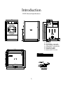
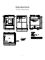
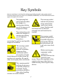
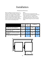
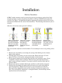
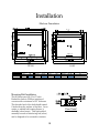
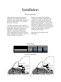
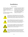
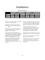
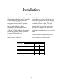
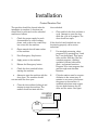
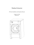
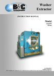
Washer-Extractor
HI Series Installation and Operation Manual
B&C Technologies
Panama City, FL
(850) 249-2222
(850) 249-2226 FAX
www.bandctech.com
Revision 1.2
08/20/2009
Table of Contents
Introduction
Customer Service
Replacement Parts
General Specifications
4
4
5
Safety Information
Key Symbols
Safety Checklist
5
7
8
Installation
Theory of Operation
Inspection and Uncrating
Dimensional Clearance
Foundation
Drain Connection
Electrical Installation
Water Connection
Steam Connection
External Chemicals
Function Test
Operation
Routine Maintenance
13
15
16
17
19
20
22
23
25
27
28
33
Decomissioning
38
B&C Technologies
Panama City, FL
(850) 249-2222
(850) 249-2226 FAX
www.bandctech.com
Introduction
HI Series Washer-Extractors
The HI line is the industrial fixed
mount washer-extractor series of machines
from B&C Technologies. It is an open
pocket washer-extractor with a large door
opening for easy and quick loading and
unloading. It has been developed for the
institutional and industrial market, and is
suitable for commercial laundries, hotel,
food processing plants, factories and other
places where laundry might be process
The design allows for top
performance at lowest possible operation
cost and investment. The flexible electronic
control center ensures that maximum
productivity is obtained.
The HI series utilizes high quality
material, such as 304 (18/8) stainless steel
in vital parts in contact with the wash
solution. It has a stainless steel cabinet for
long life with easily removable panels.
The key advantages of this series are
the simplicity of the microprocessor and the
electronic AC drive system, which utilizes
only one motor. The system allows for
washing and extraction at any speed and
mechanical action to suit any textile fiber
used today and tomorrow. A heavy duty
computer analyzed and tested frame isolates
objectionable vibrations and the high speed
final extraction saves time and energy in the
finishing operation.
The main bearing is located outside
the wash solution and will not be damaged,
should the shell seals leak. The machine is
provided with two V-seals, which are very
reliable and will last for many years. The
calculated life expectancy of the bearing is
in excess of twenty years.
The five compartment, side mounted
supply dispenser for powder and liquid
detergents are standard and the machine is
designed to accept the connection of 5
additional external chemical lines and
pumps. More chemical connections are
available as an option.
The HI series is also prepared to
accept the connection of water reuse
systems. These systems can be installed
separate or on top of the machine. They are
available in either single or dual tanks for
maximum savings of water up to 40%. The
tanks can be equipped with or without
steam or electrical heat depending on
installation and operation. The water reuse
system is programmable by the machines
electronic control center.
Customer Service
For technical assistance, call:
Phone: (850)-249-2222
FAX: (850) 249-2226
e-mail: [email protected]
Web: www.bandctech.com
In Thailand
Phone: +66 (0) 2740-5511
FAX: +66 (0) 2740-5522
e-mail: [email protected]
Web: www.accuratethai.com
Replacement Parts
In the event that literature or replacement
parts are required, contact your local
distributor, or contact B&C Technologies at
the above phone numbers/internet
addresses.
4
Introduction
HI-85 General Specifications
6
4 4
152 100 100
58.3
1482
52.4
1332
46.5
1182
62.6
1590
7.7
196
7.25
184
35.6
905
62.6
1590
43.7
1110
54.5
1385
3X 15.2
386
4
101
6.1
155
4
101
A - AIR VENT
B - HOT WATER, 1 INCH NPT
C - COLD WATER, 1 INCH NPT
D - STEAM INLET, 3/4 INCH NPT
E - ELECTRICAL INLET
F - CHEMICAL SIGNAL
G - DRAIN OUTLET, 3 INCH
1
25
15.75
400
51.6
1310
15.75
400
13A
7A
6.1
155
[email protected] (17)
Floor Detail
61.4
1560
5
15A
15A
Introduction
HI-125 General Specifications
1.25
(32)
3
(76)
6
Key Symbols
Anyone operating or servicing this machine must follow the safety rules in this manual.
Particular attention must be paid to the DANGER, WARNING, and CAUTION blocks which
appear throughout the manual
The lightening flash
and arrowhead within
the triangle is a
warning sign alerting
you of the presence of
dangerous voltage.
This warning symbol
indicates the presence
of hot surfaces that
could cause serious
burns. Stainless steel
and steam lines can become
extremely hot and should not be
touched.
The exclamation point
within the triangle is a
warning sign alerting
you of important
instructions
concerning the machine and possible
dangerous conditions.
This warning symbol
indicates the presence
of possible dangerous
pinch-points. Moving
mechanical parts can
crush an/or sever body
parts.
This warning symbol
alerts you to the
presence of possible
dangerous drive
mechanisms within
the machine. Guards
should always be in place when the
machine is in operation. Be careful
when servicing any drive mechanism.
Before servicing any
equipment, make
certain it is
disconnected from the
electrical power
source. Never allow operation of the
machine when any safety device is
malfunctioning. Never bypass safety
devices.
This warning symbol
indicates the presence
of possibly dangerous
chemicals. Proper
precautions should be
taken when handling
corrosive or caustic material.
7
Introduction
Safety Checklist
Before Initial start up of a B&C HI Series
washer extractor perform the following
safety check:
operation,. Consult the service manual, or
call a qualified service technician. If
additional information is required, contact
your local distributor or call the
manufacturer of the machine.
A. Make sure all electrical and plumbing
connections have been made in
accordance with applicable codes and
regulations.
Before servicing any
equipment, make certain it
is disconnected from the
electrical power source.
Never allow operation of
the machine when any
safety device is malfunctioning. Never
bypass safety devices.
B. Make sure the machine is grounded
electrically.
C. Make sure the machine has flexible
water fill and drain connections of the
correct size, length and type, with no kinks,
and that they are securely attached and/or
clamped.
Before machine is placed in operation, the
door safety interlock must be checked for
proper operation as follows:
A. When the washer is energized
electrically and in operation, the loading
door must be locked in the closed position.
Verify this by attempting to open the
loading door when the machine is
operating. If necessary, check the door
safety interlock and sensors for proper
operation. Consult the service manual, or
call a qualified service technician if
necessary.
B. When the washers loading door is
open, it should not be possible to
start the machine. Verify this by attempting
to start the washer with the door open. Also,
close the door without locking it and verify
that it is not possible to start the machine
with the door not locked. If necessary,
check the door lock sensors for proper
8
Introduction
Safety Checklist
To provide personal safety and keep the
machine in proper working order, follow all
maintenance and safety procedures
presented in this manual. If questions
regarding safety arise. Contact the factory
immediately.
3.2 Excessively high water level is
evident.
3.3 Machine is not connected to a
properly grounded circuit.
Use factory authorized spare parts to avoid
safety hazards.
Do not bypass any safety devices in the
machine.
Never operate the
machine with a bypassed
or disconnected out-ofbalance switch. Operating
the machine with severe
out-of-balance loads could
result in personal injury
and serious equipment damage.
Operator safety
Never insert hands or
objects into basket until it
has completely stopped.
Doing so could result in
serious injury
To ensure the safety of machine operators
the following maintenance checks must be
performed daily.
1. Prior to operating the machine, verify
that all warning signs are present and
legible. Missing or illegible signs must be
replaced immediately. Make certain
that spares are available.
2. Check door interlock before starting
operation of the machine, see safety
check list.
3. Do not attempt to operate the machine if
any of the following conditions are
present:
3.1 The door does not remain securely
locked during the entire cycle.
9
Introduction
Safety Checklist
Safe Operation Environment
where floor space is shared with equipment
sensitive to radio frequency
emissions. All machines that are shipped to
CE countries are equipped with this
filter and comply with the EMI regulations.
Safe operation requires an appropriate
operating environment for both the
operator and the machine. If questions
regarding safety arise, contact the factory.
Environmental Conditions
5. Elevation. If the machine is to be
operated at elevations over 3280 feet
(1000 meters) above sea level, pay special
attention to water levels and electronic
settings ( particularly temperature) or
desired result may not be achieved.
1. Ambient temperature. Water in the
machine will freeze at temperatures of 32F
(0C) or below. Temperatures above 120 F
(50C) will result in more frequent motor
overheating and, in some cases,
malfunction or premature damage to solid
state devices that are used in the machines.
Special cooling devices may be
necessary.
6. Chemicals. Keep stainless steel surfaces
free of chemical residues to avoid corrosion.
7. Water damage. Do not spray the
machine with water. Short circuiting and
serious damage may result. Repair
immediately all seepage due to faulty
gaskets, etc.
2. Humidity. Relative humidity above 90%
may cause the machine’s electronics or
motors to malfunction or may trip the
ground fault interrupter. Corrosion
problems may occur on some metal
components. If the relative humidity is
below 30% belts and rubber hoses may
eventually develop dry rot. This condition
can result in hose leaks, which may cause
hazards external to the machine in
conjunction with adjacent electrical
equipment.
Do not place volatile or
flammable fluids in any
machine. Do not clean the
machine with volatile or
flammable fluids such as
acetone, lacquer thinners,
enamel reducers, carbon
tetrachloride, gasoline, benzene, naphtha,
etc. Doing so could result in serious
personal injury and/or damage to the
machine.
3. Ventilation. The need for make-up air
openings for such laundry room
accessories as dryers , ironers, water
heaters, etc. must be evaluated
periodically. Louvers, screens, or other
separating devices may reduce the
available air opening significantly..
Machine Location
1. Foundation. The concrete floor must be
of sufficient strength and thickness to
handle the floor loads generated by the
machine at high extract speeds.
4. Radio Frequency Emissions. A filter is
available for machines in installations
10
Introduction
Safety Checklist
iinstall the supplied steam filter may void
the warranty.
2. Service/ Maintenance Space. Provide
sufficient space to allow comfortable
performance of service procedures and
routine maintenance. This is especially
important in connection with machines
equipped with AC inverter drives. Consult
installation instructions for specific details.
3. Compressed Air. For machines requiring
compressed air service, best
performance will be realized if air is
provided at a pressure of 80-100psi (5.4-6.7
bar). Large capacity machines could
experience door seal failures if compressed
air service is interrupted.
Replace all panels that are removed to
perform service and
maintenance procedures.
Do not operate the
machine with missing
guards or with broken or
missing parts. Do not
bypass any safety devices
4. Drainage System. Provide drain lines or
troughs large enough to accommodate
the total quantity of water that could be
dumped if all machines on the site
drained at the same time from the highest
attainable level. If drain troughs are
used, they should be covered to support
light foot traffic
Input and output services
1. Water pressure. Best performance will be
realized if water is provided at a
pressure of 30-85 psi (2.0-5.7 bar).
Although the machine will function properly
at lower pressure, increased fill time will
occur. Water pressure higher than 120
psi (8.0 bar) may result in damage to
machine plumbing. components failure (s)
and personal injuries.
5. Power. For personal safety and for proper
operation, the machine must be
grounded in accordance with state and local
codes. The ground connection must
be to a proven earth ground, not to
conduits or water pipes. An easy-access
disconnect switch should be provided.
2. Optional Steam heating pressure. Best
performance will be realized if steam
pressure is provided at a pressure of 30-80
psi (2.0-5.4 bar). Steam pressure
higher than 125 psi (8.5 bar) may result in
damage to steam components and
may cause personal injuries. For machines
equipped with optional steam heat,
install piping in accordance with approved
commercial steam practices. Failure to
Ensure that a ground wire from a proven
earth ground Is connected to the ground lug
in the electrical junction box on this
machine. Without proper grounding
personal injury from
electrical shock could
occur and machine
malfunctions may be
evident. Computercontrolled machines must
have a proper ground to
prevent computer
11
Introduction
Safety Checklist
malfunctions.
procedures and routine preventive
maintenance is especially important for
machines equipped with AC drives.
Always disconnect power and water
supplies before a service technician
performs any service procedure. Where
applicable, steam and/or compressed air
supplies should also be disconnected before
service is performed
Misuse
Even though this machine is an atmospheric
vessel, never use it for any purpose other
than washing fabrics.
AC Inverter Drive
1. Never wash petroleum-soaked rags in the
machine. This could result in an explosion
Machines equipped with AC drives require
special attention with regard to the
operating environment.
2. Never wash machine parts or
automotive parts in the machine. This could
result in serious damage to the basket.
1. An especially dusty or linty environment
will require more frequent cleaning of the
AC drive cooling fan filter and of the AC
drive itself.
3. Never stone wash in the machine. It
could wear the basket and serious damage
might occur to the machine.
2. Power line fluctuations from sources such
as an interruptible power supplies (UPS)
can adversely affect machines equipped
with the AC drive. Proper suppression
devices should be utilized on the incoming
power to the machine to avoid problems.
4. Never use the machine for dying and
with harsh chemicals that can cause
corrosion and other health hazards.
5. Never allow children to play on or
around this machine. Death or serious
injury can result if children become trapped
in the machine. Do not leave children
unattended while the machine door is open.
these cautions apply to animals as well.
3. A clean power supply free from voltage
spikes and surges is absolutely essential for
machines equipped with the AC drive.
Nonlinear inconsistencies (peaks and
valleys) in the power can cause the AC
drive to generate nuisance errors. If
voltage is above 240V for 200 V
installations or above 480V for 400V
installations, a buck/boost transformer is
recommended. If voltage is above 240V
or 480V, a buck/boost transformer is
required unless the factory advises
differently.
4. Sufficient space to perform service
12
Installation
Theory of Operation
The B&C HI model uses a single-speed
motor to drive the cylinder via V-belts in all
speeds. The cylinder is supported by two
spherical roller bearings located in split
pillow block housings made of cast steel.
bottom of the shell via a steam injector. The
steam is controlled by a steam valve that is
programmed by the EL6.
The cylinder is perforated, allowing water to
pass through and drain from within during
drain and extract steps. Lifting ribs inside
the cylinder lift the load from the wash
solution and allow the load to tumble and
falling back into the solution when the load
reaches the approximate 10-11 o’clock or 12 o’clock positions. This mechanical action
removes soil from the fabric. Furthermore,
the lifters are perforated on the top so that
water can cascade over the goods and wet
them quickly. This reduces water
consumption as water is picked up at the
cylinder’s lowest point and lifted and
splashed over the goods at the highest point
as the cylinder rotates.
The motor is controlled by the computer
control located in the front and the AC
inverter drive located in the rear panel. Any
speed can be programmed for any wash
cycle. Some speed ranges are blocked out
for programming due to safety reasons.
These speed ranges are the ones that the
machine cannot operate at due to
resonance. This speed range is not
important and normally speeds for wash or
extraction are not selected within this range.
Any wash speed in the range of 10-50 RPM
and extraction speeds 150-560 RPM can be
programmed. Further any reversing action
can be programmed. Normal reversing
action is 16 seconds forward, pause for 4
seconds, and 16 seconds reverse. Any
temperature between 70F to 200F (20-95C)
can be programmed. Any water level in the
range of the machine parameters can be
programmed in centimeters. The computers
will automatically provide safety levels for
steam injections and door operations.
A stainless steel door is provided for loading
and unloading. A door lock system
prevents operation of the machine when the
door is open. The door is locked during
operation utilizing a solenoid and a
manual latch for safety reasons. The door
lock is provided with magnetic sensor to
indicate that the machine is locked and
provide for start of the machine when the
door is closed and locked.
Water entry into the machine is through
electromagnetic water valves controlled by
the computer. The computer also controls
the drain, supply dispenser, any external
liquid supplies, steam injection and any
other vital functions of the wash program.
The computer can even record cycles and
data of importance that could be used for
maintenance purpose.
The AC drive, brake unit, contactor, circuit
overload protectors, input power supply
connections, external supply connections,
and control transformer are behind a cover
of the rear/side of the machine.
The supply dispenser is mounted on the left
side of the machine and is accessed by
The steam, if installed is injected in the
13
Installation
Theory of Operation
unlatching the cover door. Supplies, both
liquid and powder; may be added by
pulling the dispenser cups out and placing
the appropriate supply in each. Supplies are
flushed into the machine at the proper time
in the cycle, controlled by the EL6.
Holes are provided in the top of the supply
dispenser (HI-125) or at the rear of the
machine (HI-85) for connection to an
external, central liquid supply unit. Electrical
connections are provided for the liquid
supply unit on a terminal strip inside the
rear control module. Refer to page 22 for
connection details.
14
Installation
Inspection and Uncrating
Delivery inspection
NOTE!
Keep the manuals, installation instructions
and the wiring diagrams which accompany
the machine in a safe place for ready
reference. They have been included with
the machine at no charge. Additional copies
are available at a nominal charge.
Upon delivery, visually inspect crate,
protective cover, and unit for any visible
shipping damage. If the crate, protective
cover, or unit are damaged or signs of
possible damage are evident, have the
carrier note the condition on the shipping
document before the shipping receipt is
signed, or advise the carrier of the
conditions as soon as it is discovered.
Remove the crate and protective cover as
soon after delivery as possible. if any
damage is discovered upon removal of the
crate and/or protective cover, advise the
carrier and file a written claim immediately.
Customer Service
If literature or replacement parts are
required contact the source from whom the
machine was purchased or contact :
B&C Technologies
(850) 249-2222
(850) 249-2226 FAX
[email protected]
www.bandctech.com
for the name of the nearest authorized parts
distributor.
A record of each machine is on file with the
manufacturer. The serial number decal is
located at the rear of the machine. Always
provide the machine’s serial number and
model number when ordering parts or
when seeking technical assistance.
15
Installation
Dimensional Clearances
Note
When installing the washer-extractor, it is
important to allow adequate clearance on
all sides of the machine. When multiple
machines are installed, it is important to
allow for the specified minimum clearances
between machines. The following table
shows recommended minimum clearances
for the various freestanding models.
(A) Minimum rear clearance
(B) Minimum clearance between
machine and wall
(C) Minimum clearance between
machines
(D) Minimum front clearance
The dimensions are approximate and
subject to normal manufacturing tolerances.
If exact dimensions are required for
construction purposes, request certified
drawings from the factory. We reserve the
right to make changes at any time without
notice.
UNITS
Metric
UNITS
US
mm
in
760
30
mm
in
455
18
mm
in
455
18
mm
in
850
33
HI Series
A
B
C
D
16
Installation
Machine Foundation
All B&C washer-extractors must be secured by the use of machinery anchor bolts. High
strength machinery anchors should be embedded in 3500 psi (24000 N/m2) reinforced
concrete. See Figure. For detailed information regarding the machine anchor bolt, see the
instructions included with the anchor bolts themselves. The following information is just an
example.
After the concrete has cured, proceed as follows:
Select a carbide drill bit
with a diameter equal
to the anchor diameter.
Drill hole to any depth
exceeding the desired
embedment.
Clean hole or continue
drilling to accommodate drill fines
(concrete dust).
Please wear eye protection.
Drive the anchor into
the hole through material being fastened
until washer is flush
with material.
Expand bolt by
tightening the anchor
3 to 5 turns, or to the
specified torque requirements.
Place the machine adjacent to the foundation. Do not attempt to move it by pushing on the
sides.
1. Remove the wood skid by unscrewing the carriage bolts holding it to the bottom
frame of the machine.
2. Carefully place the machine over the anchor bolts. Raise and level it 1/2 inch
above the floor on four points, using spacers that can be removed.
3. Fill the spaces between the machine base and floor with machinery grout. Grout
completely under the frame members. Remove front panel and rear panel to
gain access to all frame members. Force grout under the machine base until all
voids are filled.
4. Remove the spacers carefully, allowing the machine to settle into the wet grout.
5. Attached the mounting bolt washers and lock nuts to the anchor bolts after the
grout has hardened. Tighten the lock nuts by even increments-one after the
other-until all are tightened evenly and the machine is fastened securely to the
floor. The nuts should be tightened in a diagonal fashion, which will help ensure
equal tension at all anchor points.
17
Installation
Machine Foundation
4
101
3X 15.2
386
6.1
155
4
101
15.75
400
51.6
1310
15.75
400
1
25
6.1
155
[email protected] (17)
61.4
1560
HI-125
HI-85
HI-125
Static floor load
kN
lbs
7.56
1700
19.53
4390
HI-85
Static pressure
kN/m2
lbs-ft2
5.01
104.64
10.64
222.22
Dynamic floor load Dynamic pressure Dynamic Frequency
kN
lbs
kN/m2
lbs-ft2
Hz
17.39
3910
11.52
240.6
9.65
25.58
5750
13.93
290.93
8
Mounting Bolt Installation
The HI Series uses 5/8-11 x 8” bolts.
Embed the bolts in 3500 psi reinforced
concrete with a minimum of 12” thickness.
The threaded end of the bolt should extend
2 inches from the surface of the floor. As an
option, a welded bolt locating fixture is
available (rebar frame). This rigid welded
assembly is made of reinforcing rod (rebar)
and is designed to be encased in concrete.
Floor Detail
18
Installation
Drain Connection
A drain system of adequate capacity is
essential to the machine performance.
Ideally the water should empty through a 3
inch vented pipe directly into a sump or
floor drain. See figure.
Before any deviation from specified
installation procedures is attempted, the
customer or installer should contact the
manufacturer. Increasing the drain hose
length, installing elbows, or causing bends
will decrease drain flow rate and increase
drain time, impairing machine performance.
If the drain arrangement is inadequate, the
machine will not extract and will not
discharge water properly.
A flexible connection must be made to a
vented drain system to prevent an airlock or
siphon effect. If proper drain size is not
available or practical, a surge tank is
required. A surge tank in conjunction
with a sump pump should be used when
gravity drainage is not possible, such as in
below-ground-level installations.
See table below for specific drain
information.
Drain Sizing
Drain connection Size
Drain flow capacity
Recommended drain pit size
Units
Metric
US
mm
in
liters/min
gpm
liters
gal
HI Series
76.2
560
850
3
150
212.5
Drain Construction
Rear of machine
Rear of machine
Vent
Drain Pipe
Drain Pipe
Steel Grate
Waste Line Tee
Drain Trough
Waste Line
Strainer
Waste Line
19
Installation
Electrical Installation
The AC drive requires a clean power supply
free from voltage spikes and surges. A
voltage monitor should be used to check
incoming power. The customer’
s local power company may provide such a
monitor.
If input voltage measures above 240V for a
200 V drive or above 480V for a 400V
drive, either ask the power company if their
representative can lower the voltage or
install a bucking transformer kit available
from the manufacturer. Voltages above
250V and 490V require additional
measures. Contact the distributor or the
manufacturer for assistance.
The AC drive provides for an internal
circuit breaker. A separate circuit breaker
governs the control circuit.
This machine must be installed, adjusted, and serviced by a qualified
electrical maintenance personnel familiar with the construction and
operation of this type of machinery. They must also be familiar with the
potential hazards involved. If this warning is not observed, personal injury
or equipment damage resulting in voiding the warranty may result.
When controlling the AC drive with a parameter unit, the machine’s
computer and its safety features are bypassed. This would allow the
basket to rotate at high speeds with the door open. When using a
parameter unit to control the AC drive, a large sign should be placed on
the front of the machine warning people of the imminent danger.
Never touch terminals or components of the AC drive unless power is
disconnected and the “CHARGE” indicator LED is off. The AC drive
retains potential deadly voltage for some time after the power is
disconnected. There are no user-serviceable parts inside the AC drive.
Tampering with the drive will void the warranty
Dangerous voltage are present in the electrical control boxes and at the
motor terminals. Only qualified personnel familiar with electrical test
procedures, test equipment, and safety precautions should attempt
adjustments and troubleshooting. Disconnect power from the machine
before removing the control box cover, and before attempting any service
procedures.
20
Installation
Electrical Installation
200-240V
380-480V
Machine Max Amps Breaker Wire Size Max Amps Breaker Wire Size
HI-85
21
30
10ga / 4mm
11
15
10ga / 4mm
HI-125
32
40
8ga / 10mm
16
20
10ga / 4mm
Use wire sizes indicated in the chart for runs
up to 50 feet (15m). Use next larger size for
runs of 50 to 100 feet (15-30m). Use 2 sizes
larger for runs greater than 100 feet (30m).
Note! Do not use phase adders (roto-phase)
on inverter driven equipment!
Note! Wire sizes shown are for copper,
THHN, 90 conductor per NEC article 310
(USA).
For personal safety and for proper
operation, the machine must be grounded
in accordance with state and local codes
and in the USA in accordance with the
National Electric Code, article 250-96.
The machine should be connected to an
individual branch circuit not shared with
lighting or other equipment.
The ground connection must be to a proven
earth ground, not to conduit or water pipes.
The connection should be shielded in a
liquid tight or approved flexible conduit with
proper conductor of correct size installed in
accordance with National Electric Code
(USA) or other applicable codes. The
connection must be made by a qualified
electrician using the wiring diagram
provided with the machine. See the
Electrical Connection data Chart for correct
wire sizes.
Do not connect the ground to the neutral
(N) leg at the terminal strip.
If a DELTA supply system is used, the high
leg may be connected to L1, L2 or L3,
as the machines are equipped with control
transformer.
21
Installation
Water Connection
Individual hot and cold plumbing lines with
individual shut-off valves must be available
to the machine. Hot water should be
minimum of 160F (70C). If lower
temperature water is used the machine
should be equipped for steam heating to
heat the wash solution to desired
temperature. Best performance will be
realized if water is provided at a pressure of
30-85 psi (2-7 Bar). Although the machine
will function properly at lower pressures,
increased fill times will occur.
Use flexible hoses and install separate
screen filters in the lines to keep rust and
other foreign particles out of the solenoid
valves. Hang the hoses in a large loop. Do
not allow the hoses to kink. The water
connections to the machine should be
supplied by a hot and cold water line of
least the sizes shown in the table below.
Installation of additional machines will
require proportional larger water lines, see
table.
To avoid eventual water hammer in the
water line, suitable devices to reduce the
water hammer should be installed.
Flush the water system for at least two
minutes prior to initial use.
NUMBER OF
MACHINES
1
2
3
4
5
6
DN
25
25
40
40
50
50
SUPPLY LINE PIPE SIZES
HI-85
HI-125
Inch
DN
Inch
1
32
1-1/4
1
32
1-1/4
1-1/2
50
2
1-1/2
50
2
2
63
2-1/2
2
63
2-1/2
22
Installation
Steam Connection
Never touch internal or external steam pipes, connections, or
components. These surfaces can be extremely hot and will cause severe
burns. The steam must be turned off and the pipe, connections, and
components allowed to cool before the pipe can be touched
Steam requirements are shown in the table
below. Failure to install the supplied steam
filter may void the warranty.
For machines equipped with optional steam
heat, install piping in accordance with
approved commercial steam practices.
MODEL
STEAM INLET and CONSUMPTION:
Steam inlet size
Required steam to heat bath 10F (5.55C)LOW
Required steam to heat bath 10F (5.55C)HIGH
Average Steam consumption per cycle
MODEL
STEAM INLET and CONSUMPTION:
Steam inlet size
Required steam to heat bath 10F (5.55C)LOW
Required steam to heat bath 10F (5.55C)HIGH
Average Steam consumption per cycle
23
Units
DN
kg
kg
kg
HI-85
in
lbs
lbs
lbs
20
3.15
4.77
72
Units
DN
kg
kg
kg
3/4
7
10.5
158
HI-125
in
lbs
lbs
lbs
20
3.8
5.8
88
3/4
8.4
12.76
194
Installation
External Chemical Supplies
Wear Eye and hand protection when handling chemicals. Always avoid
direct contact with raw chemicals. Read the manufacturer’s directions for
accidental contact before handling chemicals. Ensure that an eye-rinse
facility and an emergency shower are within easy reach. Check at regular
intervals for chemical leaks.
The following procedures must be observed
when connecting any chemical injector to
the washer-extractor. See the figure for a
typical supply injection system setup.
Undiluted chemicals dripping can damage
the machine. Therefore, all chemicals
supply dispenser pumps should be mounted
below the washer’s injection point.
point All
dispenser tubing should also run below the
injection point. Loops do not prevent drips
if these instructions are not followed. Failure
to follow these instructions could damage
the machine and void the warranty.
Supply Dispenser
Chemical Dispenser
Pump
PCV Pipe
24
Installation
External Chemical Supplies
The supply compartment on the B&C HI125 model is located on the left side of the
machine. Supply cups can be accessed by
open the dispenser lid. The supply cups can
be removed and filled as desired. Supply
compartments are numbered 1,2,3,4 and 5
from the rear of the machine to the front.
External supply connections for the B&C
HI-85 washer-extractors are located on rear
of the machine at the vacuum breaker.
Hose connections should be made via the
threaded connectors. See figure.
1.
Remove plugs from base. See
figure.
2.
Install the supplied chemical
nipple, using teflon tape.
3.
Insert tubes onto the nipples, using
small hose clamps or wire ties to
prevent the hose from slipping off.
External supply connections for the B&C HI
washer-extractors are located on top of the
supply dispenser. Hose connections should
be made via the strain relief. See figure.
1.
2.
3.
4.
The chemical flush water valve (relay 12)
should be used with each chemical signal
(see the EL6 programming manual for
details).
Remove plugs from base. See
figure. Plugs are assembled inside
the tubing ring.
Install strain relief, included in the
seal nut.
Insert tubes through base. Do not
remove cups. Tube should extend
into the plastic cup, with the
exception of the softener tube,
which should be routed to
the outside of the cup.
Tighten the seal nut to prevent
tubing from escaping the assembly.
HI-125 Strain Relief for
Supply Connections
HI-85 Supply Connections
25
Installation
Electrical Connections
Connection terminals are located in the rear
control box for output signals to the
chemicals injection supply pump.
Do not attempt to increase fuse rating as
this cause damage to the washer-extractor
circuitry.
Terminals SUPPLY 1 through SUPPLY 8
provide signals for external chemical supply
pumps. The signal is a maximum 1 amp at
24V 50/60Hz.
Any injection system pump, which requires
24-220V AC must be powered by a
separate external power source.
Attempting to obtain power from the machine terminals may damage the
machine circuit and/or the chemical injection system.
Consult the chemical injection supply system instructions for operational
details.
26
Installation
Control Function Test
The machine should be cleaned after the
installation is complete. A function test
should then be executed on the unloaded
machine as follows:
1.
2.
door unlocked.
c.
Check the proper supply for such
characteristics as correct voltage,
phase, and cycles to be certain they
are correct for the machine.
If the door lock and interlock are not
functioning properly, call a service
technician.
Open manual shut-off water valves
to the machine.
3.
Press Emergency Stop button.
4.
Apply power to the machine.
5.
Release the Emergency button.
6.
Check the door interlock before
starting the machine.
a.
Attempt to start the machine with the
door open. The machine should
not start with the door open.
b.
Close and lock the door and start a
cycle. Attempt to open the door
while the cycle is in progress. The
door should not open.
7.
For standard processing, select
program 30 by pressing key 3 and
key 0 on the keypad. Then press
enter and the Start key. Run the
complete program, checking
operation of water inlet valves,
drain , and extract functions.
Program 30 is a test program that
goes through most machine
functions.
8.
Cylinder rotation must be counterclockwise in the extract step. If
rotation is not correct, disconnect
the power to the machine. A
qualified technician must reverse
any two leads between the AC
drive and the motor. See figure.
Close the door without locking it and
attempt to start the machine. The
washer should not start with the
INVERTER
DRIVE
TERMINALS
M
27
W V U
T3 T2 T1
Operation
HI-85 Door Lock Operation
The lock system uses a "push-to-open /
push-to-close" style mechanism which
differentiates it from any other door lock in
the industry. This design was developed as
a result of analyzing the shortcomings of
other door lock mechanisms on the market.
It hence has many fundamental safety &
mechanical advantages.
Periodic Maintenance
>The door should be tested every day for
safe operation by trying to start a program
with the door open. If the machine will
begin operation in this state it should
immediately be removed from service,
locked out, and a qualified service
technician called to repair it.
>If the door lock is malfunctioning in any
way, the machine should immediately be
removed from service, locked out, and a
qualified service technician called to repair
it.
>The door lock pin and handle hinge
should be lubricated with "silicon spray
lube" monthly. This product is available at
almost any auto parts store. This procedure
does not require any disassembly.
>The door handle nose bushing should be
checked for wear and cracking monthly. It
should be replace when it is cracked,
missing, or worn out.
>The door lock tongue and lock pin
alignment should be checked monthly and
adjusted as needed.
>For detailed instructions on door
alignment, request TSB009 when
contacting technical service.
Operation
Opening & Closing
To open the door the machine must not be
running a wash program -- "Program N"
should be displayed on the EL6. Simply
push and release the door handle with the
palm of your hand. As you push the handle
in the door lock solenoid will energize and
the pin will retract and release the door.
Then as you release the pressure on the
handle the door will be free and you can
pull it open. To close the door swing it
closed, then push the handle firmly until
you hear the solenoid engage, releasing the
door lock pin to lock the door. When you
start a wash program the door lock is
securely disabled so that the door cannot be
accidentally opened.
·
28
Operation
Wash Program Execution
After power is applied to the machine, and
the internal diagnostics are complete, the
machine is ready for a program to be
chosen. The display will show:
Temperature
If the end condition of the segment is a
temperature, the display will show:
WASH3 TEMP = 35C
PROGRAM N. _
where 35C is the actual temperature of the
wash solution. By pressing TEMP the
display will change, for 3 seconds, show the
required step temperature for advance.
Pressing INC or DEC allows modification of
the value for the step. Pressing LEVEL
allows you to see the current water level.
Pressing the TIME key shows the watch dog
timer (WDT) value for the current step.
Using the keypad, type the number of the
program you wish to run followed by the
ENTER key. Standard programs are
outlined in the EL6 stock program list,
included with the machine. The display will
change to show the fist cycle of the selected
program:
PRWH 1 EXECUT.?
Press START to execute the program, or
RESET to return to program selection.
While the program is executing, the display
shows the current segment of the program,
and the ending condition of the segment.
See the following examples:
Time
If the end of the step calls for a time to
elapse, the display shows:
RINSE1 T = 2m 30s
In this case, the display shows the time left
in the step. INC and DEC allow you to add
or subtract minutes for the current cycle.
TEMP allows you to view the current water
temperature, and LEVEL shows the current
water level.
Note: During heating, fill and drain phases,
the WDT (watch dog timer) is activated. If
the phase does not complete before the
timer expires, an alarm will be displayed
indicating that the particular phase did not
complete within the time allowed.
Level
If the end requirement of the segment (step)
is a particular water level, the display will
show:
RINSE1 LVL=cm12
cm12 is the actual water level in the
machine (12 centimeters). Pressing the
LEVEL key shows, for 3 seconds, the
required value to advance. If INC or DEC is
pressed, you can temporarily modify the
value for the current step. Pressing TEMP
allows you to see the current temperature of
the water. Pressing the TIME key shows the
watch dog timer (WDT) value for the
current step.
Single Step Execution
A single step or cycle of a wash program
can be executed. At the main prompt, enter
zero for the program number. For two
seconds, the display changes to:
29
Operation
Wash Program Execution
the PAUSE key. The display will begin
showing a time, counting up as long as the
machine remains paused. Pressing the
START key will restart the program at the
point it was paused. As long as the
machine is paused, all other WDT (watch
dog timers) are paused as well.
SINGLE CYCLE
Then, using the INC and DEC keys, you
may choose the cycle you wish to run
(PREWASH, WASH, RINSE, SPIN,
UNROLL). When you have selected you
cycle, confirm by pressing ENTER. The
display changes to:
RUN?
Advance
While any program is running, you can end
the current step and advance to the next
one by pressing the ADVAN key. If the key
is pressed during a spin, the spin will be
aborted, and the standard spin slow down
time will be activated.
Pressing the START key will start the
machine.
Partial Program
A program can be partially run. After
selecting the program you wish to execute,
the display will show:
Halting a Program
PRWH 1 EXECUT.?
At any time during the execution of the
wash program, the running program can be
terminated by pressing the STOP key.
Instead of pressing ENTER to execute the
program, press the ADVAN key. The cycles
within the program will be displayed
incrementally. Choose the point at which
you would like to begin, and press the
START key. The machine will begin
operation from this point.
Water Level Refresh
While a program is running, if the water
level drops to a level which is 3cm below
the target level, cold water will automatically
be added to replenish the level.
Displaying the Current
Program and Step
Unbalance
If, during a spin segment, the load is
excessively out of balance, the spin will
stop, and a redistribution of the goods will
take place. If three consecutive out of
balances occur, the machine will end the
program. After the first unbalance, the
balance indicator will light on the control
panel.
While the machine is in operation, pressing
then ENTER key will cause the display to
show the current program number and step.
PRG 1 STP 3
Soak
You can insert a pause at any point of the
wash program with the exception of
distribution and spin. To do so, simply press
Power Failure
30
Operation
Wash Program Execution
If the power fails during execution of a
program, and is of less than one second, it
is ignored. If the failure is longer than one
second, the machine stops. Upon
restoration of mains power, the display
shows CYCLE CONTINUE? and the power
failure indicator illuminates on the front
panel. If you wish to restart the program at
the point in which power failed, press the
START key. At this point, the program
restarts at the point of power failure and the
power failure indicator turns off. If you wish
to cancel the program, simply press the
RESET key. This function is not active
while a single cycle is running.
LEVEL FAULT
Indicates a problem with the level sensing
system. This could be a loose or cracked
water level tube, the level sensor, or the
level sensing circuit. As long as the system
detects a problem with the level sensing
system, the machine will be inoperable.
The buzzer can be disabled with the RESET
TEMP FAULT
Indicates a problem with the temperature
sensing circuitry, temperature probe, or
wiring. The machine continues to function,
although auxiliary heating (if equipped) is
not possible. The Temperature fault
indicator on the control panel will be
illuminated.
End of Program
When a program has completed, the
message PLEASE WAIT is displayed and
the buzzer sounds for 40 seconds. The
buzzer can be silenced by pressing the
RESET key. If the temperature or water
level are out of bounds, the display shows
the offending value and the door cannot be
opened.
WDT TEMP EXPIRED
Indicates the programmed temperature was
not reached within the allotted time. The
most common cause is a malfunctioning
auxiliary heating system. A short WDT time
and very cold water can also cause this
problem. Pressing the START key will
cancel the alarm.
Malfunction Alarms
The state of the water temperature and
water levels are constantly monitored to
prevent functioning problems with these
devices. Watch Dog Timers (WDT) are
used to prevent cycle failure when
temperatures, fills, drains, and levels don’t
meet programmed values. In the event of a
program fault, the buzzer sounds and the
display changes to show the fault:
WDT LEVEL EXPIRED
Indicates the programmed level was not
reached within the allotted time. The most
common causes:
During Fill
>
Faulty water inlet valve
>
Low or no water pressure
>
Faulty drain valve
>
Problem with water level tube
Pressing START will continue the program,
31
Operation
Wash Program Execution
The message appears at the start of a
program, and is repeated at the beginning
of each wash program until reset (see
function 217 in the EL6 Programming and
Operation Manual for full details). Before
resetting the alarm, PERFORM ROUTINE
MAINTENANCE AS OUTLINED
ELSEWHERE IN THIS MANUAL.
while RESET will cancel the program.
During Drain
>
Drain valve blocked
>
Drain hose blocked
>
Faulty Drain Valve
Press RESET to end the program.
OVERLOADED!
For further information regarding access
functions and programming, see the EL-6
Computer Programming and Operating
Instructions manual, included with the
machine.
Indicates a fault in the drive system. On
inverter driven equipment, indicates a drive
fault, on non inverter driven equipment,
indicates a motor overload condition. Press
RESET to clear the fault. If this fault recurs
during the next wash program, contact a
qualified service technician.
DOOR OPEN!
Indicates the door is not closed properly.
This fault disables the machine until cleared,
and aborts a program if active. Press
RESET to clear the fault.
DRAIN
Indicates a water level of greater than 2cm a
the onset of spin. The machine will resume
the spin when the level falls below the
threshold. Press RESET to abort the cycle.
Maintenance Request
After 450 wash programs have completed,
the machine will call for maintenance:
MAINTENANCE
32
Maintenance
Routine Maintenance
Routine maintenance maximizes operating
efficiency and minimizes downtime. The
maintenance procedures described below
will prolong the life of the machine and help
prevent accidents.
Daily, weekly, monthly, and quarterly
checklist are provided at the end of this
section. Laminate the checklists to preserve
them for repeated copying. Operators and
technicians are encouraged to add checks
specific to their machine’s particular
application. When possible, space is
provided on the checklists for this purpose.
technician.
4. Check door interlock before starting
operation:
a. Attempt to start the washer with the
door open. The washer should not
start with the door open.
b. Close the door without locking it
and attempt to start the machine.
The machine should not start with
the door open.
c. Close and lock the door and start a
cycle. Attempt to open the door
while the cycle is in progress. The
door should not open. If manual
latch is moved out of position the
machine should stop.
The following maintenance procedures
must be performed regularly at the required
intervals.
Install all panels that are
removed to perform
service and maintenance
procedures. Do not
operate the machine with
missing guards or with
broken or missing parts.
Do not bypass any safety
If the door lock and interlock are not
functioning properly, call a service
technician.
End of the day
devices!
1. Clean the AC drive box air filters.
Daily
a. Snap off the external plastic cover
which contains the filter. Remove the
foam filter from the cover.
1. Inspect water inlet valve hose
connections on the back of the machine for
leaks.
b. Wash the filter in a mild soap
solution or vacuum it clean.
2. Inspect steam hose connections for
leaks, where applicable.
2. Clean the door gasket of residual
detergent and foreign matters.
3. Verify that insulation is intact on all
external wires and that all connections are
secured. If bare wire is evident, call a service
3. Clean the automatic supply dispenser
and the lid inside and out with mild
33
Maintenance
Routine Maintenance
detergent. Rinse with clean water.
#2 grease. Never mix two types of
grease, such as petroleum and
silicone.
4. Clean the washer’s top, front and side
panels with mild detergent. Rinse with
clean water.
b. Pump the grease gun slowly,
permitting only the following number
of strokes:
1. Bearing grease fitting, 2 strokes
2. Seal grease fitting, 1 stroke.
5. Leave loading door open at the end of
each day to allow moisture to evaporate.
NOTE: Leave loading door open at end of
each complete cycle to allow moisture to
evaporate. Unload the machine promptly
after each completed cycle to prevent
moisture build up.
Do not pump the grease gun if grease
comes out of the bearing housing.
This can result in over lubrication, causing
damage to bearings and seals.
Weekly
2. If the machine is provided with
automatic lubricators, check that they are
injection grease. Normally the last for
approximately one year. Mark new
lubricators with installation date
1. Check the machine for leaks.
a. Start an unloaded cycle to fill the
machine.
3. Clean the AC drive fins:
a. Remove the AC drive box cover.
b. Blow the fins clean using compressed
air at a pressure of 60-90 psi
( 4-6 Bar) or by using canned
compressed air. Use care to avoid
damaging cooling fan or other
components.
b. Verify that door and door gasket do
not leak.
c. Verify that the drain valve is
operating. If water does not leak out
during the prewash segment, drain
valve is closed and functioning
properly.
NOTE: No amount of visible foreign matter
should be allowed to accumulate on fins or
the finger guard.
Monthly
NOTE: Disconnect power to the machine at
its source before performing the monthly
maintenance procedures.
4. Use the following procedures to
determine if V-belts require replacement or
adjustment. Call a qualified service
technician in either case.
1. Each month or after every 200 hours of
operation, lubricate bearing and seals. See
instructions on the machine.
a. Use a premium grade lithium based
a. Check V-belts for uneven wear and
frayed edges.
34
Maintenance
Routine Maintenance
b. After disconnecting power to the
machine and removing all panels
necessary for access to the drive
belts, use the following method to
verify that the V-belts are properly
tensioned. Belt deflection should be
measured as close to the center of
the span length as possible. A set
force should be applied in the center
of the length, as specified in the
table below. Belt tension is adjusted
by turning the set screw on the idler
pulley. Turning the set screw
clockwise tighten the belt, and vice
versa.
Turn
Pulley
More Tension
Less Tension
c. Verify that V-belts are properly
aligned by checking pulley
alignment. Place a straightedge
across both pulley faces.
The straight edge should make
contact with the pulleys in four
places.
See figure.
STRAIGHT EDGE
35
Maintenance
Routine Maintenance
Quarterly
5. Remove back panel and check overflow
hose and drain hose for leaks.
NOTE: Disconnect power to the machine
before performing the quarterly
maintenance procedures.
6. Unlock the hinged lid and check the
supply dispenser hoses and hose
connections.
1. Tighten door hinges and fasteners, if
necessary.
7. Clean inlet hose filter screen:
a. Turn water off and allow valve to
cool, if necessary.
2. Tighten anchor bolts, if necessary.
3. Check all painted surfaces for bare metal
(matching paint is available from the
manufacturer.)
b. Unscrew inlet hose and remove
filter screen.
c. Clean with compressed air and
reinstall. Replace if worn or damage.
a. If bare metal is showing, paint with
primer or solvent-based paint.
8. Tighten motor mounting bolt lock nuts
and bearing bolt lock nuts, if
necessary.
9. Use compressed air to clean lint from
motor.
10. Clean external water and steam filters.
b. If rust appears, remove it with sand
paper or chemical means. Then
paint with primer or solvent-based
paint.
4. Clean steam filter, where applicable. See
picture of steam filter.
1. Turn off steam supply and allow time
for the valve to cool if necessary.
NUT
2. Unscrew nut.
3. Remove element and clean.
4. Replace element and nut.
36
ELEMENT
Maintenance
Routine Maintenance
Care of stainless steel
when possible.
Maintain the natural beauty of stainless steel
and prolong its service life by following
these steps.
6. Discolorations or heat tint from
overheating may be removed by scouring
with powder or by employing special
chemical solutions.
1. Ordinary deposits if dirt and grease can
be removed with detergent and water.
The metal should be thoroughly rinsed and
dried after washing. Periodic cleaning
will help to maintain the bright surface
appearance and prevent corrosion.
7. Sanitizers or sterilizing solutions should
not be left in stainless steel equipment
for prolonged periods of time. They often
contain chlorine, which may cause
corrosion. The stainless steel should be
cleaned and rinsed thoroughly of any
solution containing chlorine.
2. Contact with dissimilar metal should be
avoided whenever possible. This will
help prevent galvanic corrosion when salty
or acidic solutions are present.
8. When an external chemical supply
system is used, make certain that no
siphoning of chemicals occurs when the
washer-extractor is not in use.
Highly concentrated chemicals can cause
severe damage to stainless steel and
other components within the machine.
Damage of this kind is not covered by the
manufacturers warranty. Locate the pump
below the washer’s injection point to
prevent siphoning of chemicals into the
machine
3. Salty or acidic solutions should not be
allowed to evaporate and dry on stainless
steel. They may cause corrosion. Ensure
that the stainless steel is wiped clean
of acidic solution residues.
4. Deposits that adhere to the stainless steel
should be removed, especially from
crevices and corners. When using abrasive
cleaners, always rub in the direction
of the polish lines or grain of the stainless
steel to avoid scratch marks. Never
use ordinary steel wool or steel brushes on
the stainless steel. Use stainless
steel wool or soft non-metal bristle brushes..
5. If the stainless steel appears to be rusting
the source of the rust may actually be
an iron or steel part not made of stainless
steel, such as a nail or screw. One
remedy is to paint all carbon steel parts with
a heavy protective coating.
Stainless steel fasteners should be used
37
Decomissioning
Decommissioning
supply to the machine.
d. Allow time for residual water in the
machine to drain. Then disconnect
drain hoses from the machine.
e. Disconnect necessary plumbing on
the re-circulation system, if
applicable.
In the event that the machine must be
decommissioned, follow the following steps:
1. Remove the chemical injection supply
system, if applicable.
a. Have a qualified electrician
disconnect power to the chemical
injection supply system and the recirculation pump at their source.
b. Using the manufacturer’s
instructions, carefully remove the
chemical injection supply system
from the machine. Make certain that
no chemicals supplies come in
contact with skin or clothing.
5. Disconnect steam hoses, if applicable
a. Turn off steam supply and allow time
for the valve to cool.
b. Disconnect steam hose from
machine.
6. Remove the machine from its foundation
pad.
a. Keep all panels in place to provide
stability when moving the machine.
b. Verify that door is closed and secure
c. Loosen and remove anchor bolts
holding the machine base to the
floor
d. Break the grout seal at each corner
of the machine, using a crowbar.
e. Place the machine on skid and bolt
the frame to the skid. This will
facilitate the removal of the machine
on to a truck.
2. Clean interior of machine, both basket
and shell.
a. Flush supply dispenser with water.
b. Run a short rinse cycle to clean
chemical residues from the interior of
the machine.
3. Disconnect electrical power.
a. Shut of main power supply at the
breaker box or main control panel.
b. Do not attempt to disconnect power
supply wires from power supply.
Have a qualified electrician
disconnect power to machine at its
source.
7. Recycle.
The manufacturer uses the highest quality
material in their products so that those
material may be recycled at the end of the
product’s service life.
4. Disconnect hoses.
a. Disconnect drain hose from sump,
gutter, or drain.
b. Turn off water supply. Disconnect
individual hot and cold water inlet
hoses from the machine
c. Disconnect the compressed air
38