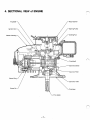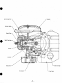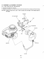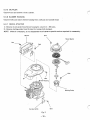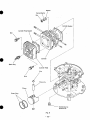
1
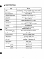
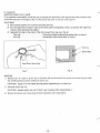
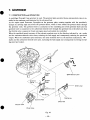
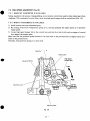
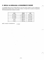
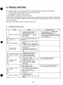
SERVICE
MANUAL
Model
EC13V
1193S122
ROBIN AMERICA, INC.
ROBIN TO WISCONSIN ROBIN
ENGINE MODEL CROSS REFERENCE LIST
WISCONSIN ROBIN
ROBIN
0
SIDE VALVE
W 1-080
W1-145
W1-145V
W1-185
W1-185V
W1-230
W 1-280
W 1-340
W 1-390
Wl-45OV
EY21W
EY44W
EY18-3W
EY25W
EY27W
EY08
EY15
EY 15V
EY20
EY2OV
EY23
EY28
EY3 5
EY40 EY45V
EY2 1
EY44
EY 18-3
EY25
EY27
OVERHEAD VALVE
WO1-115
wo1-120
WO1-150
WO1-170
wo1-210
WOl-250
WO 1-300
WO1-300V
WO1-340
WO 1-340V
WO 1-43
OV
EH11
EH12
EH15
EH17
EH21
EH25
EH30
EH30V
EH34
EH34V
EH43V
0
TWO CYCLE
WT1-125V
EC13V
DIESEL
DY23
DY27
DY30
DY35
DY4 1
WRD 1-230
WRD 1-270
-1-300
WRD1-350
WRD1-410
0
FOREWORD
I
This manual covers the construction, function and sevicing procedures of the Robin
engine model EC13V.
Good operation and a planned maintenance program as outlined
in this manual are
of vital importance in obtaining maximum engine performance, and long enginelife.
Careful observance of the instructions will result in better, saferservice work,
IMPORTANT: All information,illustrations,directionsand.specificationsinthis
book are on the basis of information available at the timeit was written.
Fuji Heavy Industries Ltd. reserves the right to make changes without incurring any
obligation whatever.
No part of this publication may be reproduced without written permission.
Recoil Starter
\
Fuel Tank
Lever
Carburetor
I:
P.T.O. Shaft
Section
Page
Title
1. SPECIFICATIONS
...........................................
2 . PERFORMANCE . . . . . . . . . . . . . . . . . . . . . . . . . . . . . . . . . . . . . . . . . . .
2 - 1 Maximum Output . . . . . . . . . . . . . . . . . . . . . . . . . . . . . . . . . . . . . .
2 - 2 Continuous
Rated Output . . . . . . . . . . . . . . . . . . . . . . . . . . . . . . .
1
2
2
2
Fuel Consumption Ratio a t
ContinuousRated Output . . . . . . . . . . . . . . . . . . . . . . . . . . . . . . . 2
. 2.3 Maximum Torque and
3. FEATURES . . . . . . . . . . . . . . . . . . . . . . . . . . . . . . . . . . . . . . . . . . . . . . .
4
. SECTIONALVIEW
of ENGIN€
3
...............................
5. DISASSEMBLY and REASSEMBLY . . . . . . . . . . . . . . . . . . . . . . . . . . . .
5-1 PreparationsandSuggestions . . . . . . . . . . . . . . . . . . . . . . . . . . . . .
5 - 2 Special Tools . . . . . . . . . . . . . . . . . . . . . . . . . . . . . . . . . . . . . . . . .
....................
5 - 3 DisassemblyandReassemblyProcedures
4
6
6
7
8
6. MAGNETO . . . . . . . . . . . . . . . . . . . . . . . . . . . . . . . . . . . . . . . . . . . . . . .
17
6 - 1 Operation of the Ignition System . . . . . . . . . . . . . . . . . . . . . . . . . . 17
6 - 2 Ignition SystemCheck . . . . . . . . . . . . . . . . . . . . . . . . . . . . . . . . . . 18
6-3 IgnitionUnit Installation . . . . . . . . . . . . . . . . . . . . . . . . . . . . . . . .
18
7. GOVERNOR . . . . . . . . . . . . . . . . . . . . . . . . . . . . . . . . . . . . . . . . . . . . . .
7 - 1 Construction and Operation . . . . . . . . . . . . . . . . . . . . . . . . . . . . . .
19
19
GovernorAdjustment . . . . . . . . . . . . . . . . . . . . . . . . . . . . . . . . . . .
High Speed Adjustment . . . . . . . . . . . . . . . . . . . . . . . . . . . . . . . . .
21
7 -2
7-3
8. BREAK IN OPERATION of REASSEMBLED ENGINE
9
. . . . . . . . . . . . . 22
.....................................
StartingDifficulties . . . . . . . : . . . . . . . . . . . . . . . . . . . . . . . . . . . .
Slow-speed out of order . . . . . . . . . . . . . . . . . . . . . . . . . . . . . . . . .
OverheatingandKnockjng . . . . . . . . . . . . . . . . . . . . . . . . . . . . . . .
TROUBLE
SHOOTING
23
9-1
9-2
9-3
9-4
9-5
9-6
9-7
23
24
24
24
24
PowerDrop ..........................................
ExcessiveFuel Consumption . . . . . . . . . . . . . . . . . . . . . . . . . . . . .
Engine Hunting . . . . . . . . . . . . . . . . . . . . . . . . . . . . . . . . . . . . . . .
OtherComplaints . . . . . . . . . . . . . . . . . . . . . . . . . . . . . . . . . . . . . .
10. CHECKS and CORRECTIONS . . . . . . . . . . . . . . . . . . . . . . . . . . . . . . . . .
.
12.
20
25
25
26
11 CLEARANCE DATA and LIMITS/TORQUE SPECIFICATIONS . . . . . . 27
MAINTENANCE and STORING . . . . . . . . . . . . . . . . . . . . . . . . . . . . . . .
12- 1 Daily ChecksandMaintenance . . . . . . . . . . . . . . . . . . . . . . . . . . . .
12-2 Every 50 Hours (10 days) Checks and Maintenance . . . . . . . . . . . .
12-3 Every 100 200 Hours (Monthly) Checks and Maintenance . . . . .
12-4 Every 500 600 Hours (Semiannual) Checks and Maintenance . . .
12-5 Every 1000 Hours (Yearly) Checks and Maintenance . . . . . . . . . . .
12-6 Preparation for Long Storage . . . . . . . . . . . . . . . . . . . . . . . . . . . . .
-
-
29
29
29
29
29
30
30
1 SPECIFICATIONS
EC13V
Model
Type
Air-cooled, 2-Cycle, Vertical Shaft, Single Cylinder Gasoline Engine
.
56 mm x 50 mm.(2.20 in x 1.97 in)
Bore x Stroke
. ,
Piston Displacement
123 cc (7.49 cu. in)
Continuous Rated Output
3.2 HP/3600 rpm (2.4 KW/3600 min" )
Max. Output
4.2 HP/4000 rpm (3.1 KW/4000 min" )
Max. Torque
0.8 kg-m/3000 rpm
Counter-clockwisefacing to P.T.O. shaft
Rotation
Forced Air Cooling
Cooling System
Gasoline Oil Mixing Type (Mixing Ratio50 : 1)
Lubrication
Lubricant
2-Cycle EngineOil
Carburetor
Horizontal Draft, Float Type
Automobile Gasoline (mixed with oil)
Fuel
Fuel Consumption Ratio
(gr/HP-h)
1
360 a t continuous rated output operation
I
Gravity Type
Fuel Feed
Approx. 2.0 liter (0.53 U.S. gal.)
Fuel Tank Capacity
I
Speed Governor
Ignition System
.
Centrifugal Flyweight Type
Flywheel Magneto Type (Solid State Igntion)
NGK BMGA or CHAMPION CJ8 Spark Plug
Recoil Starter
Starting System
Dry Weight
11.2 kg (24.7 Ibs)
400 mm (15.7 in)
Length
Dimensions Width
334 mm (13.1 in)
331 mm (13.0 in)
Height
-1-
I
2. PERFORMANCE
r\
\
2-1 MAXIMUMOUTPUT
The maximum output of the engine is the power delivered by the engine running with full throttle opening
after theengine is throughly broken in.
A brand new engine may not produce this maximum output until it has been sufficiently broken in.
2-2 CONTINUOUS RATED OUTPUT
The continuous rated outputof the engine is the power delivered by the engine running atan optimum speed
most favorable for engine life and fuel consumption. When designing an equipment driven by an engine, it is
most important to keep the power requirement
less than continuous rated output of the engine.
2-3 MAXIMUM TORQUE.and FUEL CONSUMPTION RATIO AT CONTINUOUS RATED OUTPUT
The maximum torque curve of the engine is the output torquecurve at P.T.O. shaft when the engine is running with full throttle opening.
Fuel consumption ratio at continuous rated output is the one while the engine is delivering continuous rated
output.
PERFORMANCE CURVE
kg-m
HP
"
2400
3200
2800
3600
Revolution ____) r.p.m.
-2-
4000
0
3. FEATURES
"
1. CRANKSHAFT: Forged steel crankshaft
assembled with induction hardened crankpin, precision balanced for low engine vibration, durability, greater shock loading resistance and longer life.
2. BEARINGS: Ball bearings at both ends of crankshaft and needle roller bearings a t small end and large
end of connecting rod give less friction, better radial support, maximum side loading capability
and
longer life.
3. ALUMINUM 'CYLINDERand CRANKCASE:Aluminumdie-cast
cylinderwith molded-incastiron
liner makes the engine light in weight with extra strength, durability, loweroil consumption and longer
life.
4. AIR CLEANER: Rugged dual stage. air cleaner with high efficiency,
ease of service and longer engine
life.
5 . SOLID STATE IGNITION: Solid state, high energy electronic ignition gives more precise ignition timing, hotter spark for easy starting, no breaker points to service, ease of maintenance and longer spark
plug life.
6. ALL-SPEED GOVERNOR: Rapid response mechanical flyweight type governor system is fullylubricated with oil mixed .fuel for long life and which enables more precision speed regulation and better reliability. .
This all-speed governor system enables the setting for any desired speed by simply moving the control
lever.
7. CARBURETOR: Precision modern design withbutterflythrottleandchoke.Removable
float type design gives maximum fuel economy and ease of starting.
fixed jetand
8. PISTON: High strength aluminum alloy piston--isspecially designed for durability and longer life.
9. PISTON RINGS: Two ring design. Chrominum plated top ring and perkarized second ring give smooth
running and durability.
10. FUEL TANK: Large, no rust'resin tank gives.trouble-free long operation.
-3-
4. SECTIONAL VIEW of ENGINE
Flywheel
/
\
P.T.O. Shaft
-4-
Recoil Starter
Connecting Rod
\
-5-
5. DISASSEMBLY and REASSEMBLY
5-1 PREPARATIONS and SUGGESTIONS
5-1 - 1 DISASSEMBLY
When disassembling the engine, memorize where and how each part is assembled in order to reassemble it
correctly. Tag parts if there i s a possibility of confusion.
Take care not todamage packings and gaskets, whichare fragile.
In order toprevent missing and misplacing, group related parts together, tentatively assembling them, immediately after disassembled each sub-assembly.
Handle the disassembled parts carefully, andwash them in kerosene.
Use the correct toolsin the correct way.
Standard tools required for disassembly and reassembly: .
a) Work table
b) Washing pan
c) Disassembling tools
. .
..
d) Washing oil (kerosene or gasoline), Mobile oil, Brush
e> Emery paper, Cloth
Before starting to disassemble the engine, drain fuel. (To prevent from danger and stain)
5 - 1 - 2 CLEANING before reassembly
1) Check all sliding and rotating parts, such as piston, cylinder, crankshaft and bearings for defect.
2) Wash the disassembled parts in kerosene to remove dust,dirtandcontaminated
oil thoroughly. Wash
them twice, first time remove visible dirt roughly, and second timeusing fresh kerosene.
3) After washing, blow them thoroughly with compressed air.
4) Do not wash electric parts. Wipe them with clean cloth and dry them.
5 ) Accumulated carbon on the cylinder head, gasket, piston, cylinder and
inside the muffler to be careflly
removed, and finish the piston withoil stone to get smooth surface.
6) Parts of carburetor to be washed carefully with gasoline and blow them thoroughly with compressed air.
7) Check the cable for any damage.
8) Air cleaner element shall be washed in the.detergent and dry thoroughly. Then put it to mixture of2 4
kerosene and 1 engine oil, and assemble it after squeezed well.
9) Take special care not to contaminate the parts with dust and applymobile oil on the surface in order to
prevent from &st.
-
5 - 1-3 CHECKS and CORRECTIONS before reassembly
After disassembling and cleaning the engine parts, check them and, if necessary, correct them according
the section "11. CLEARANCE DATA and LIMITS/TORQUE SPECIFICATIONS."
Gaskets and rubber pipesshall be replaced with new ones,
-6-
to
,
n
'~,
i
0
5-1 - 4 REASSEMBLY
1) Before reassembly, wash parts in kerosene and blow them with compressed air.
2) Apply mobile oil on the rotating and sliding surface.
3) Take care not ‘to contaminate the parts with dust during reassembly.
4) Be sure t o assemble those parts.provided with alignment marks by bringing the marks in alignment.
5 ) Tighten bolts, nuts and screws
to the correct torque specified. When there is no torque specification,
6)
7)
8)
9)
tighten them to torque readings appropriate to the size.
Standard Tightening Torquefor screws are as follows:
6 mm . . . . . . . . . . . . . 90 kg-cm (6.5 ft-lbs)
8 mm . . . . . . . . . . . . . . 250 kg-cm (1 8 ft-lbs)
10 mm . . . . . . . . . . . . . 370 kg-cm (26.7 ft-lbs)
If small screws are tightened too hard, they may get broken. Tighten the large size nuts such as ones for
the magneto flywheel, enough by
giving hammer blows on the socket wrench handle.
When tightening the several screws fastening the single part, tighten them all evenly, by alternately tightening diagonally located pairs.
Do not applyoil to the part towhich packings or sealing agent t o be applied.
When engine is completely reassembled, make sure that thereis no parts remained.
During the assembly, turn themoving part by hand to check for friction and noise.
After the completion of reassembly, turn the engine by hand, and check if there is any disorder or loose
members.
5 - 2 SPECIAL TOOLS
Part No.
Tool
Use
Applicable
Model
2099500407
Flywheel Puller
(without bolt).
For pulling off
Flywheel
All Robin
gasoline engines
-7-
Shape
5-3 DISASSEMBLY and REASSEMBLY PROCEDURE
5 - 3 - 1 FUEL TANK and FUEL TANK BRACKET
1) Disconnect fuel pipe from carburetor.
2) Remove mounting bolts, and detach fuel tank and fuel tank bracket from crankcase and blower housing.
CAUTION: Repface fuel pipe once a year in order to prevent from the danger of fuel leakage caused by
the cracks.
n
Tank Band
Fuel Tank Bracket
I
Fuel Pipe
Fig. 1
-8-
0
5-3-2 A I R CLEANER
1) Remove air cleaner cover and element.
2) Unscrew two nuts and bolts which clamped air cleaner
base plate to carburetor and remove
base plate.
In reassembly, wash element based on the following procedure before reassembly:
1) Wash outer and inner elements with detergent and dry them thoroughly.
2) Soak them in the mixture of 2 4 kerosene and 1 engine oil, and squeeze the outer element to remove
excess oil.
-
5-3-3 CARBURETOR
1) Remove governor rod and rod spring from carburetor.
2) Removecarburetorfromcylinderblock.
’
.
.
In reassembly:
Refer to section “7. GOVERNOR.”
5-3-4GOVERNOR LEVER
1
1) Remove governor lever from governor shaft.
2) Remove governor spring from control lever.
In reassembly:
Refer to section “7. GOVERNOR.”.Assembly shall be made correctly including engine speed adjustment.
Screw
Cleaner Element
Fig. 2
-9-
\
Cleaner Cover
5-3-5 MUFFLER
Unscrew nuts and remove it from cylinder.
5-3-6 BLOWER HOUSING
Unscrew bolts and remove blower housing from crankcase and cylinder head.
,
5-3-7 RECOILSTARTER
1) Remove recoil starter from blowerhousing by unscrew 4 x M6 bolts.
2) Remove starting pulley from flywheel by loosing bolts clamped.
NOTE: Unless it is necessary, do not disassemble recoil starter as special tools are required for reassembly.,
Muffler
Bolt
Recoil Starter
Nut
”-%
Starting Pulley
Bolt
Cylinder Baffle
Fig. 3
- 10-
5-3-8 MAGNETO and FLYWHEEL (Fig. 4)
1) Remove flywheel from crankshaft.
Apply a socket wrenchover the nut at the endof
crankshaft and give the wrench handle a sharp
blow with a hammer.
Remove nut and spring washer. Attach flywheel
puller. to. flywheel as illustrated in Fig. 4, turn
the center bolt clockwise until flywheel comes
loose enough t o be removed.
2) Remove spark plug cap from high tension
cable
of ignition coil. Then, remove ignition coil from
crankcase.
In reassembly:
Refer t o section “6. MAGNETO.”
Ignition Coil
=u
Flywheel Puller
Fig. 4
Bolt
Flywheel
/
I
Spark Plu’g Cap
Fig. 5
- 11 -
Crankshaft
5 - 3 - 9 CYLINDER HEAD
1) Remove spark plug from cylinder head.
2) Unscrew four head bolts and remove cylinder head from cylinder.
3) Remove cylinder head gasket from cylinder.
In reassembly:
1) Clean carbon from combustion chamber and dirt from between the cooling fins of cylinder head.
Check its mounting face for distortion.
2) Use new cylinder head gasket.
NOTE: Cylinder head gasket must be placed folded edge upside (To the cylinderhead).
--
3) Cylinder head fin must be placed in parallel with crankshaft.
Tightening torque for head bolt is 180 7 220 kg-cm ( 13 16 ft-lbs).
4) Tightening torque for spark-plugis 250 300 kg-cm (1 8 22 ft-lbs) for a new spark plug.
-
5-3-10 CYLINDER
1) Remove cylinder from crankcase by removing nut, springwasher and washer.
2) Remove cylinder gasket.
In reassembly:
Clean carbon deposit from cylinder head and combustion chamber.
CAUTION: Without cleaning the carbon deposit, i t may damage the pistonand inner surface of cylinder
when reassembling.
ylinder
Replace
a new one.
Intake of cylinder should be positionedto the left againstview from blower side. Applyoil to piston ring
and cylinder walls. After assembling the cylinder securely, make sureif the crankshaft rotates smoothly.
Tightening torque for cylinder is 180 220 kg-cm (1 3 16 ft-lbs).
-
-
CAUTIONS:
1 ) When fastening cylinder, tighten four nuts evenly.
2) Before reassembling cylinder, apply oil to needle bearing located at the small end of connecting
rod.
5-3-1 1 PISTON
1) Remove piston pin clips of both sides.
2 ) Pull piston pin out of the piston, and remove the needle bearing from the small end of connecting rod.
CAUTION: In order not to damage piston, hold the piston firmly and pull out piston pin. Also due caution should be exercised when disassembling needle bearing.
3) Remove piston rings from piston, expanding the open ends of therings.
- 12-
n
Washer
Spring Washer
Nut
Fig. 6
- 13-
In reassembly:
.PISTON
RINGS (Fig. 7 and 8 )
If an expander is unavailable, install the ring by placing the open ends of thering on first land of piston, then
spread the ring only far enough to slip over the piston and carry it into the correct groove.
CA U T I 0NS:
I ) Be extremely careful not to distortand break the ring.
2) Put the open ends o f piston rings to the knock pins in thegrooves. (This is to prevent the rings from
rotation while operating the engine.)
3) Assemble the rings in the order of the 2nd ringand then top ring. (Fig. 8)
Top ring .....................
Chromium plated surface (looks white silver in colour)
2nd ring ......................
Perkarized surface (looks dark in colour)
Top Ring
Second Ring
Fig. 8
Fig. 7
.PISTON
1 ) Position the “F” mark of piston top to flywheel side and reassemble the piston and connecting rod with
the needle bearing by gently striking the piston pin.
CAUTION: Apply oil to the needle bearing before reassembling it to piston pin.
2) Assemble piston pin clip.
CAUTION: Replace piston pin clip if there is any looseness after reassembling it.
3) Be sure that piston and connecting rod move smoothly after reassembled.
- 14 -
r”\
\ ’
5 - 3 - 1 2 CRANKCASE
Unscrew 5 bolts which fasten upper and lower parts
of the crankcase, and divide the crankcase into two parts
by tapping with soft hammer, and detach crankshaft connecting
rod assy.
In reassmbly:
1) Before reassembling upper and 'lower parts of the crankcase, check bearing and oil seals if there is any
damage, and in case of any damage being found, replace them with new ones.
2) Apply oil to the bearings of crankcase and ascertain that there is n o warp on the lip of oil seal.
Tightening torque is 90 100 kg-cm (6.5 7.0 ft-lbs).
Clean the joint of both crankcases and apply sealing agent to the fitting surfaces of bothcrankcases. Assemble the crankshaft and join both crankcases withpress (or tap them with a soft hammer)having extra
care not to damage the oil seal.
CAUTION: When reassembling the crankcase, tighten
the diagonally located pairs of bolts according to
-
-
the specified tightening torque.
NOTE: After reassembling the crankshaft to the crankcase, check if the crankshaft rotates smoothly,
5-3-13 CRANKSHAFT and CONNECTING ROD ASSY
Do not take apart the crankshaftand connecting rod.
Crankshaft and connecting rod assembly is supplied as a spare part.
Crankshaft
- 15-
5-3-14GOVERNOR’PLATE
’
Pull out governor plate, governorsleeve from crankshaft.
In reassembly:
Reassembly is just reverse of disassembly sequence.
5 - 3 - 1 5 GOVERNORSHAFT
1) Unscrew 2 screws and remove governor yoke.
2) Pull out governor shaft from crankcase.
NOTE: Do not disassemble unless it is required.
In reassembly:
Refer t o section “7. GOVERNOR.”
5-3-16CONTROLLEVER
Unless it is required, do not remove control lever from crankcase.
For disassembly and reassembly procedures, refer to section “7. GOVERNOR.”
Flange Bolt
Choke Rod
. Choke Lever
Governor Yoke
I’
Governor Plate
Governor Shaft
Fig. 10
- 16-
a
6. MAGNETO
-
EC13V engine is equipped with a pointless Solid State Ignition system. Thisis a circuit breaker type ignition
device which utilizes the power transist,oras an element for controlling electric current.
This system is free from start-up failure due to dirty, burntor oxidized point surfaces, low ignition efficiency
because of moisture, rough' breaker point surface and incorrect timingresulting from worn mechanical parts.
6-1 OPERATION of the IGNITION SYSTEM
This system is referred to as T.C.I. (Transistor Controlled Ignition) system.
As illustrated in Fig. 1 1, this is a simple system, consisting of a flywheel with magnetic fields,an ignition
coil with built-in transistor, and lead wires to spark
plug and stop switch.
Rotation of the flywheel generates a voltage on the
primary side of the ignition coil.
By this voltage, electric current (11 ) flows through
the resistor (RI) to thebase of the power transistor.
This current actuates the transistor to permits the
amplified flow of current (IC).
With further rotation of the flywheel, the voltage at
the point @ reaches up to thetrigger voltage of the
thyrister (SCR) and the current ( 1 3 ) flows eliminating current (11). At this moment, current (IC)is cut
off abruptly resulting in high voltage on the secondary side of the ignition coil, which in turn fires the
spark plug.
RESISTOR
Fig. 12
.
*
IGNITION COIL WITH BUILT-IN TRANSISTOR
BLACK
a
0
Fig. 1 1
WIRINGDIAGRAM
SOLID STATE IGNITION
IGNITION COIL
T.C. IGNITION CIRCUIT
- 17 -
6-2 IGNITION SYSTEM CHECK
In the event of malfunction of the ignition system, check the
followings at first:
0
Broken, frayed, loose or disconnected ignition wires.
0
Faulty spark plug-wet, dirty, insulation broken
or incorrect plug gap.
'
If difficulty is experienced in starting the engine or if engine misses firing, the strength of the ignition spark
should be checked:
Remove spark plug-then with the ignition cable connected
to it, lay the spark plug on a convenient metal
part of the engine so that the gap can be observed as you rotate the crankshaftseveral times by means of the
recoil starter. If a good strong spark occurs, the ignition system can be eliminated as the source
of trouble. If
there is a weak spark or no spark at all, check the ignition system as follows':
1) Check to make sure that the external magnet, mounted on the flywheel
is in a good condition.
2) Since the solid state ignition unit is self-contained, the only testing which can be performed is on the
secondary coil resistance.
Using a good quality ohm-meter, check the secondary coil resistance between the plug terminal of the ignition cord and the coreof the ignition coil.
This resistance reading should be approximately 13,000 ohms f 10%.If the resistance reading is infinite, this
indicates open winding in the ignition unit, a loose or broken spark plug connector or a failed high tension
lead.
If a very low reading is taken, the secondary coil is probably shorted. If, after testing, the ignition unit
itself
is determined to be faulty, then itwill have to bereplaced.
n
6-3 IGNITION UNIT INSTALLATION
'\..
When installing the ignition unit on the crankcase,
use a non-metallic feeler gauge
to measure the airgap between the ignition coil and flywheel. The ignition coil can be moved t o adjust the air-gap by loosening its holddownscrews.
Adjust the air-gap between 0.4 0.5 mm (0.0 16"
-
-
0.02").
Fig. 13
NOTE:
I f the flywheel is removed, wipe off oil and grease thoroughly from the tapered portion of the crankshaft and flywheel before reassembly.
Tightening Torque for flywheel nut
390
I
- 420 kg-cm (28 - 30 ft-lbs)
- 18 -
J
7. GOVERNOR
7 - 1 CONSTRUCTION and OPERATION
A centrifugal flyweight type governor is used. The governor plate, governorsleeve and governor yoke are installed in the crankcase, and lubricated by the oil mixed -fuel.
As the enginespeedfluctuates,flyweightsonthegovernorplate,rotatingtogetherwith
the crankshaft,
changes its opening angle and moves the governor sleeve, which in turn rotates the governor shaft through
the governor yoke. The governor lever
is connected to the extending part of the governor shaft and this
governor lever is connected to the carburetor throttle lever through the governor rod at the other end; thus
the throttlevalve is opened or closed and engine speed andoutput are controlled.
When the crankshaft speed increases, all the relevant members move in the direction indicated by
marks
and the carburetor throttle valve closes, reducing the fuel supply and consequently reducing the speed and
output. When the crankshaft speed decreases, the same members move in the direction indicated by -e
marks and the carburetor throttlevalve open, increasing the fuel supply and consequently recovering the
failing speed and output.
+a-
Throttle Valve
Choke Valve
Fig. 14
- 19-
7-2 GOVERNORADJUSTMENT
The governor
system
should
adjusted
be reassembly
at
f-7
by the following
procedures.
\
1) Connect governor rod and rodspring to carburetor throttlelever and governor lever, then install governor
lever t o governor shaft.
NOTE: Never tighten the set screw for the adjusting plate at this time, and do not fix adjusting plate,
governor leverand governor shaft.
2) Connect governor lever and control lever with governor spring, and install control lever to crankcase.
And the governor adjustmentis t o be made in the following sequence:
a)Attachthe
governor lever onthegovernor
shaft.
b) To the governor shaft, fasten temporarily the
adjusting plate with nut and spring washer.
c) To the governorlever, fasten temporarily the
adjusting plate with screw and washer assy.
At this moment, the adjusting plateis free t o
move. (See Fig. 15.)
d) Pushdown
the adjustingplatedownward
and tighten the screw. (See Fig. 16.)
e,) Setthespeedcontrol
lever at the position
“High,” and tighten the nut. (SeeFig. 17.)
I
Nut
Fig. 15
Screw and Washer Assy
fl
\,
Fig. 17
Fig. 16
- 20 -
”
7-3 HIGH SPEED ADJUSTMENT (Fig. 16)
7-3-1 WHEN NO TACHOMETER
Is AVAILABLE
Unless required in the process of disassembling, do not remove control lever and/or other related parts from
crankcase. If it is necessary to remove them, never turn high speed stopper bolt on controllever (Fig. 18).
7-3-2 WHEN A TACHOMETER IS AVAILABLE
1) Install control lever and other related parts.
2) By turriing control lever with governor spring on it, increase gradually the engine speed up
to specified
engine speed.
3) Locate high speed stopper bolt on the control lever and lock it so that it will work as stopper of control
lever against the stopper plate.
Make sure that the governor spring is hooked in the same hole on the governor lever as original. There are 5
holes on the governorlever.
Normally, hook governor spring in the center hole.
Speed Control Lever
\
Choke Lever
Governor
\
Fig. 18
- 21 -
8. BREAK IN OPERATION of REASSEMBLEDENGINE
f-l
>\
An overhauled engine must be carefully broken in to get proper surface condition on newly installed parts.
Especially when cylinder, piston or piston rings are replaced, a thorough break in operation is indispensable,
The recommended breakin schedule is as follows:
I
LOAD
"
1 SPEED
I
NO LOAD
1 2,000 rpm
I
NO LOAD
I 3,000 rpm
NO LOAD
.
I O minutes
I
I
10 minutes
I
I
60 minutes
I
TIME
3,600 rpm
, _
1.6 HP
I
1
1
I
3,600rpm
I
~~
3.2 HP
3,600 rpm
NOTE: Use 25: I oil mixed fuel for break in period.
- 22 -
i
a
9: TROUBLE SHOOTING
For a gasoline engine to start and run satisfactorily, the following three requirements must
be met:
1) A proper fuel-air mixture is supplied to the combustion chamber.
2) An appropriate compression in the cylinder.
3) Good spark at correct time to ignite the mixture.
If all the three requirements are not met simultaneously, an engine cannot be started. There are also other
factors such as heavy load at'starting or too longan exhaust pipe causing a high back pressure, which contribute to hard starting.
The most commoncauses of engine troubles aregiven below.
9-1 STARTING DIFFICULTIES
Remedy
Cause
Preventive measure
1) I f contaminated, wash in gasoline, re-
1) Use spark plugs of specified heat range.
Defects in spark plug
move foreign matters and dry.
2) If spark plug is broken or lost insulation, replace plug.
3) Adjust spark gap to 0.6 0.7 mm.
Do not use poor grade.oil.Clean air
cleaner and avoid dust entry.
2) DO not hit or bend the center electrode of
the spark plug a t adjusting or the insulator
may get damaged.
Defects in high-tension
cord
I f cord is burnt or damaged, replace the
ignition coil unit.
Defects in magneto
1 ) If wire or insulation is broken, replace
magneto.
2) If magnetism is weak, re-magnetize ( a t
the magneto maker) or replace flywheel.
-
1 ) I f switch i s faulty (short circuit),
replace or repair.
Other defects in
electric system
2) If primary wire is grounded to the
Gas leak through head
gasket or other parts
2) If head bolts are loose, tighten.
3) If spark plug is loose, tighten. .
engine body, insulate it with insulating
tape.
1 ) If headgasket is defective, replace.
4) I f spark plug is defective, replace.
1) If piston is worn, replace.
2) If cylinder is worn, re-bore and use over.
Defects in piston
assembly
1 ) Keep air cleaner always clean.
2) Do not use poor grade oil.
size piston and piston ring.
3) I f piston rings are worn, replace.
4) If piston rings are stuck, clean or
replace rings.
Defects in fuel tank
system
Defects in carburetor
1) Clean clogged tank outlet.
2) Cleanclogged fuel strainer.
3) I f incorrect fuel is poured into tank or
water is mixed, drain tank completely
and fill it with correct fuel.
4) When fuel pipe is locked with air,
discharge air.
1 ) If clogged with dust, clean.
2) If defective,replace.
Clean j e t s and other orifices, if they are
clogged.
- 23 -
1 ) Be sure t o use a filter when adding fuel.
2) Use mixture (gasoline 50 : 1 ) as fuel.
Cause
Defects in carburetor
Excess load
1 ) Start engine with fully open choke
valve and half open throttle valve.
1) Never close choke valve when engine is
2) Remove drain plug from crankcase, and
2) When stopping the engine, run it a t slow
close fuel cock, repeat starting operation several times t o discharge excess
fuel.
Defects in fuel supply
I
Preventive measure
Remedy
1
If fueloverflows, checkneedle valve seat
for wear. Replace, if necessary.
warm.
speed for a while. This practicenot only
favorably affects next starting,but also
improves engine life.
3) Clogged air cleaner results in too rich air
fuel mixture.
Clean it throughly.
Be careful clogged carburetor.
1) If tension of transmission belt is too
tight, tension.
reduce
2) If load is still too heavy, install a clutch.
I r
Piston Or Connecting
Rod seized
1 ) If piston seizes, repair or replace.
2) If connecting rod large end or small end
seize, replace.
~
1 ) Do not use poor grade oil.
2) Use fuel of proper mixing ratio.
. .
~~
~
~~
~~
9-2 SLOW-SPEED out of order
Most defects listed ascauses for starting difficulty arealso causes for faulty slow-speed operating.
9-3 OVERHEATING and KNOCKING
1) If too much carbon deposits are accumulated
in the combustion chamber, remove it.
2) If the heat range of the spark plug is too cool, replace it with a correct one, i. e. NGK BM6A or CHAMPION CJ8.
3) If the air-fuel mixture is too lean, clean jets and otherpassages in the carburetor.
Clean the air cleaneralso.
4) If the load is in excess, reduce it below the specified continuous load.
r\
~
.I
9-4 POWER DROP
1) If the cylinder, piston or piston rings are worn, replace them or re-bore the cylinder and fit oversize piston and piston rings. Replace or clean piston rings if they are stuck in the grooves.
2) If the carburetor is out of order, re-adjust or clean it.
3) If the spark plugis faulty (contamination, gas leakage or faulty insulation), clean it or replace it.
4) If combustion gas leaks through the head gasket, re-tighten the clamping screws.
If the gasket is faulty, replace it.
5) If the magneto is faulty, replace them.
6) If the air cleaner is clogged, clean.it.
7) If the fuel system is clogged, clean it.
8) If the oil seals at the crankshaft are worn and the compressedgas are leaking, replace them.
9-5 EXCESSIVE FUEL CONSUMPTION
1) If air-fuel mixture is too rich, clean jets andpassages in carburetor.
2) Ifthrottle
theshaft
of carburetor is worn,
replace
throttle
shaft.
(carburetor)
3) If fuel is leaking, re-tighten screws or replace faulty part.
4) If the engine suffers power drop accompanied with excessive fuel consumption, trouble-shoot by following step 9-4.
- 24 -
‘rj l
1
9-6 ENGINE HUNTING
1) If the governor lever, governor shaft, governor spring or other members are incorrectly adjusted,
re-adjust
or correct them.
2) If the fuel-air mixture is too lean, clean and adjust the carburetor.
3) If the governor springis distorted permanently, replace it.
4) If the governor sleeve is not functioning correctly, correct it.
5) If the flyweight or the governor sleeve is worn, replace it.
6) If the governor shaft does not move smoothly, correct it.
9-7 OTHER COMPLAINTS
1) Fuel overflows from carburetor.
If the fuel flows into the air cleaner or much fuel flows'into the crankcase while the engine is standing
still (over-flowing),the needle valve or the floatis fauity. Correct or replace them.
,2) If the engine suddenly stops with abnormal noise, the piston or the crankshaft
or the connecting rod is
seized. Repair or replace them.
3) If the engine produces abnormal noise during operation, be sure to stop the engine and do not start it
again before the cause is removed.
If the cause of the trouble cannot be found, contact your dealer and
ask them for service.
- 25 .-
IO. CHECKS and CORRECTIONS
After disassembling and cleaning the engine parts, check them, and if necessary, correct them according to
the correction table.
The correction table applies whenever engines are repaired. Its contents shouldbe thoroughly understood by
those who undertake the repairing.
Its specifications must be abidedby to effect correct maintenance.
Followings are the terms employed in the correction table.
CORRECTION
All operations performed on the engine parts for the purposeof improving or recovering the engine performance, consisting of repairs, readjustments, and replacements.
STANDARD SIZE
The design dimension of the part without the tolerance.
CORRECTION TOLERANCE
The tolerance on there-finished part dimension or on the readjusted dimension.
CORRECTION LIMIT
changes, due to
The limit on the part and adjustment, beyond which any dimensional and functional
wear, burn, and othercauses will adversely affect the normal engine performance.
USE LIMIT ,
The limit, beyond which the partis no longer usable, due to defectsin function or strength.
NOTE: All dimentions in the "CLEARANCE DATA AND LIMITS/7ORQUE SPECIF1CATIONS"are given
in millimeter, except where otherwise specified.
- 26 -
11. CLEARANCEDATA and LIMITS/TORQUE SPECIFICATIONS
I
-LIMIT
USE
LIMIT
REMARKS
0.2
S .T.D . $156
056.25
056.50
O.S.
O.S.
Bore
Roundness
0.1 5
S.T.D. G55.96
0
-0.01 5
0,s. 056.21
O.S. 056.46
Outside
Diameter
1
I
G12
Top
2nd
Clearance between
pisto
r inn
ag
nd
piston aroove
I
Clearance between
piston and cylinder
I
Fit between piston
and piston pin
r-
wR
i ditnhg
Piston pin O.D.
I
end Large
+0.060
2.0
+0.040
1
I
I
a
Large end side or
small
side
end
Parallelism and
Twist between large
end and small end
bores
-0.1
Correct
Cylinder
gauge
Boring
Micrometer
Replace
Cylinder
gauge
Replace
- 0.74
TOP
2nd
TOP
2nd 2.35
@12
@24
0.004
--
0.09
0.07
I
I
I
I
I
0.1
- 0.25
io.1
-0.008
I
+:'009
+0.011
0.1 5
Vernier
caliper
Replace
0.1 5
0.15
Feeler
gauge
Replace
0.25
0.25
Cylinder
gauge.
Micrometer
Replace
0.06L
0.06 L
Cylinder
gauge.
Micrometer
Replace
1.5
1.5
Feelergauge
Replace
-0.1
Micrometer
Replace
-0.03
-0.03
Micrometer
Replace
+0.020
t0.020
+0.055
t0.055
1
Max. cylinder
dia. and min.
piston dia.
Cylinder
Clearance in
radial direc-
I
0.003
-
0.027
0.5
-
0.1
I
I
I
0.055
0.055
0.7
0.7
0.1
0.1
Cylinder
gauge.
Micrometer
Cylinder
gauge
+0.020 +0.020
0
I
I
Twist
0.1 5
- 0 :
-0.003
I
Parallelism
-0.035
tion
@16
I
I
-0.035
+0.020
- 0.022
I
- 20.5
+0.040
0.05
0.03
0.04
I.D.
between
Clearance
small end I.D.
and
piston
pin
needle bearing
J.011
2.0
TOP
2nd
I.D.
Clearance between
r o d large e n d I.D.
and crank pin
needle bearing
end Small
,
0.008L-0.008T
I
1
I
Ring gap
-0.1
Diameter
f r o m bottom,
in traverse
t o p i s t o n pin
(max. dia.)
3
Width of
ring groove
e
Surface
date,
Feeler
0.01 5
Cylindricity
Piston pin hole
CORRECTION
METHOD
0.65
0.01
,
TOOL
Clearance in
radial direction
Cylinder
gauge,
Micrometer
Replace
Obtain correct
clearance by
replacing parts
Replace
Obtain correct
clearance by
replacing parts
I
0.08
0.08
0.3
- 27 -
0.3
Holding large
e n d as reference, measure
test bar, (L =
100) inserted
in small and
large e n d
Feeler
gauge
Replace
Test bar,
Dialindicator
Replace
ITEM
'
1
Large and small end
I.D. roundness &
cylindricity
STANDARD
SIZE
I
TOLERANCE
Max. 0.004
Max. 0.004
Roundness
Cylindricity
Distance between
large e n d & s m a l l
end bores
a
Roundness
Cylindricity
I
I
I
I
Crankshaft journal
$
J
~
~
'
TOOL
CORRECTION
METHOD
Replace
Micrometer
Replace
Max. 0.005
Mzx. 0.005
Micrometer
Replace
+0.003
-0.006
Micrometer
Replace
Measure
between
bearing &
crankshaft
Feeler
gauge
Replace
Supporting
assembled
crankshaft
between
centers,
measure
journal.
Dialindicator
Correct
Micrometer
Replace
-7"
-0.005
Crankpin O.D.
Roundness
Q.D.
t
i0.25
Crankpin O.D.
1t
I
Mandrels,
Micrometer
t 0.05
-0.020 -0.020
P
'
REMARKS
I
0
crankshaft
between
Runout of
crankshaft
- 0.2
0.05
I o
Dia. of small end
needle bearing
needles
-0.004
unscrew
Fixed
CHAMPION
. plug
Spark
CJ8
NGK BM6A
I
I
rl
18"(fixed)
gap
.-
plug
2
0.6
Spark
-
+0.1
1.0
0
0)
1
~~
u1
Min.
gap
Magnet
revolution:
400 r p m
5
Spark
~
Adjust
TORQUE SPECIFICATIONS
ITEM
m
Flywheel nut
.E
0).
6+ F9 , Spark plug
z?
z
?L
v)
.
Cylinder nuts
Crankcase bolts
- 420
250 - 300
- 220
390
90
-
100
REMARKS
ft-lbs
kg-ern
28
1
- 28 -
- 30
- 22
13 - 16 180
6.5 - 7.3
18
TOOL
Torque
wrench
r)
\.,
I
head
12. MAINTENANCE and STORING
The following maintenance jobs apply when the engine is operated correctly under normal conditions. The
indicated maintenance intervals are by no means guarantees for maintenance free operations during these
intervals.
For example, if the engine is operated in extremely dusty conditions, the air cleaner should-be cleaned every
day instead of every 50 hours.
12-1 DAILY CHECKS and MAINTENANCE
I
Maintenance
and Checks
I
1
them
requiringforReasons
Remove dust from whatever parts which accumuThe governor linkage is especially susceptible to dust.
lated dust.
Check external fuelleakage. If any, retighten the
loose part or replace faulty part.
Danger of causing fire
Check screw tightening. If any loose one is
found, re-tighten:
Loose screws and nuts will cause vibration
reasulting in the engine damage.
I
12-2 EVERY 50 HOURS (10 DAYS) CHECK and MAINTENANCE
Reasons for requiring them
Checks and Maintenance
Clean air cleaner
Clogged air cleaner affects engine operation.
Check spark plug. If contaminated, wash in
gasoline or polish with emery paper.
Output power is reduced and startingis made
difficult.
12-3 EVERY 100
- 200 HOURS (MONTHLY) CHECKS and MAINTENANCE
Checks and Maintenance
I
I
I
Reasons for requiring
them
- 600 HOUUS (SEMIANNUAL) CHECKS and MAINTENANCE
Maintenance
and Checks
cylinderRemove
deposit.
Remove carbon deposit from exhaust port and
muffler.
-
.
The carburetor will be clogged with dirt or dust
causing bad starting or poor operation.
Clean fuel strainer and fuel tank.
12-4 EVERY 500
'
Disassemble and clean carburetor.
I
forReasons
I
The engine output power drops.
I
requiring them
The carburetor will be dogged causing bad starting
or poor operation.
- 29
-
I
I
12-5 EVERY 1000 HOURS (YEARLY) CHECKS and MAINTENANCE
Checks and Maintenance Reasons
Perform overhaul, clean, correcfor replace parts.
for requiring them
The engine output drops andbecomes out of order.
Change piston rings.
Replace fuel pipe once a year.
Rubber pipes may be hardened andcracked by the
ozone in the air.
I
12-6 PREPARATION for LONG STORAGE
1) Perform the above 12-1 and 12-2 maintenance jobs.
2) Drain fuel from the fuel tank, carburetor float chamber and fuel lines.
3) To prevent rust in the cylinder bore, apply oil through the spark plug hole and turn the crankshaft for
several turns by hand. Re-install the spark plug.
Turn the starting pulley by hand and leave it where the resistance is the heaviest.
4) Clean the engine outside with oiled cloth.
5) Put a vinyl or other cover over the engine and store the engine in dry place.
n
',
- 30 -
Industrial
Engines