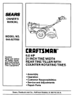
1
OWNER'S
MANUAL
MODEL NO.
917,298350
®
Caution:
Read and follow
all Safety Ru_es
and instructions
Before Operating
This Equipment
5.0 HP
241 C TJNE WIDTH
FRO ITT! E TILLER
• Assembly
• Operation
° Maintenance
• Service and Adjustment
o Repair Parts
Sears,
Roebuck
and Co., Chicago,
_L 60684 UoS°A.
Safe Operation
SAFETY
RULESPowered
for Walk-Behind
Practices
• If the unit should start to vibrate abnormally, stop the
engine (motor) and check immediately for the cause. Vibration is generally a warning of trouble.
TRAINING
,
•
Rotary Tillers
Read the operating and service instruction manual
carefully. Be thoroughly familiar with the controls and
the proper use of the equipment. Know how to stop the
unit and disengage the controls quickly.
• Stop the engine (motor) when leaving the operating
position, before unclogging the tines, and when making
any repair, adjustments, and inspections.
Never allow children to operate the equipment. Never
allow adults to operate the equipment without proper
instruction.
o Take all possible precautions when leaving the machine
unattended. Disen£tage the power take-off, lower the
attachment, shift into neutral, stop the engine, and
remove the key.
o Keep the area of operation clear of all persons, particularly small children, and pets.
PREPARATION
, Before cleaning, repairing, or inspecting, shut off the
engine and make certain all moving parts have stopped.
Disconnect the spark plug wire, and keep the wire away
from the plug to prevent accidental starting. Disconnect
the cord on electric motors.
o Thoroughly inspect the area where the equipment is to
be used and remove al! foreign objects.
o Disengage all clutches and shift into neutral before
starting the engine (motor).
o Do not operate the equipment without wearing adequate outer garments, Wear footwear that will improve
footing on slippery surfaces.
Do not run the engine indoors; exhaust fumes are dangerous.
o Never operate the tilter without proper guards, plates, or
other safety protective devices in place.
o Handle fuel with care; it is highly flammable,
- Keep children and pets away.
,
Use an approved fuel container,
° Do not overload the machine capacity by attempting to till
too deep at too fast a rate,
• Never add fuel to a running engine or hot engine.
o Fill fuel tank outdoors with extreme care. Never fill
fuel tank indoors.
• Never allow bystanders near the unit.
o Use only attachments and accessories approved by the
manufacturer of the tiller (such as wheel weights, counterweights, cabs, and the like).
o Replace gasoline cap securely and clean up spilled
fuel before restarting.
o Never operate the tiller without good visibility or light.
o Use extension cords and receptacles as specified by the
manufacturer for all units with electric drive motors or
electric starting motors.
o Be careful when tilling in hard ground. The tines may
catch in the ground and propel the tiller forward. If this
occurs, let go of tt_e handlebars and do not restrain the
machine.
, Never attempt to make any adjustments while the engine
(motor) is running (except where specifically recommended by manufacturer).
OPERATION
MAINTENANCE
AND STORAGE
• Keep machine, attachments,
working condition.
, Do not put hands or feet near or under rotating parts.
and accessories
in safe
• Check shear bolts, engine mounting bolts, and other
bolts at frequent intervals for proper tightness to be sure
the equipment is in safe working condition.
, Never store the machine with fuel in the fuel tank inside
a building where ignition sources are present, such as hot
water and space heaters, clothes dryers, and the like.
Allow the engine to coot before storing in any enclosure.
, Always refer to the operator's guide instructions for
important details if the tiller is to be stored for an extended
period.
o Exercise extreme caution when operating on or crossing
gravel drives, walks, or roads. Stay alert for hidden
hazards or traffic. Do not carry passengers.
o After striking a foreign object, stop the engine (motor),
remove the wire from the spark plug, thoroughly inspect
the tiller for any damage, and repair the damage before
restarting and operating the tiller.
Exercise caution to avoid slipping or falling.
-IMPORTANT
-
Warnings, Cautions, and Notes are a means of attracting attention to important or critical information in this manual.
CAUTION:
LOOK FOR THiS SYMBOL TO POINT
OUT IMPORTANT
SAFETY
PRECAUT!ONS. _TMEANS ooATTENTION!
BECOME ALERT! YOUR SAFETY _S
INVOLVED.
USED TO ALERT YOU THAT THERE IS
A POSSIBILITY
OF DAMAGING
THIS
EQUIPMENT,
NOTE: Gives essential information that will aid you to
better understand, incorporate, or execute a particular
set of instructions.
2
PRODUCT
CONGRATULATIONS
on your purchase of a Sears tiller.
tt has been designed, engineered and manufactured to
give you the best possible dependability and perform °
ance.
Should you experience any problems you cannot easily
remedy, please contact your nearest Sears Authorized
Service Center. Sears has competent, well trained technicians and the proper tools to service or repair this unit.
Please read and retain this manual. The instructions wilt
enabie you to assemble and maintain your tiller properly.
Always observe the "SAFETY RULES".
SPECiFiCATiONS
HORSEPOWER:
5.0 H.P.
DISPLACEMENT:
t2.57 cu. in.
GASOLINE CAPACITY:
3 QUARTS
Regular unleaded
OIL (20 oz. Capacity):
SAE 30 (or I 0W30)
Winter: SAE 5W30
SPARK PLUG (GAP .030 IN.):
Champion
RJ 19LM
MODEL
NUMBER 917.298350
SERIAL
NUMBER
DATE OF
PURCHASE
This unit is equipped with an internal combustion engine
and should not be used on or near any unimproved forestcovered, brush-covered, or grass-covered land unless the
engine's exhaust system is equipped with a spark arrester
meeting applicable local or state taws (if any). If a spark
arrester is used, it should be maintained in effective working order by the operator.
In the state of California the above is required by law
(Section 4442 of the California Public Resources Code).
Other states may have similar laws. Federal laws apply on
federal lands. See your Sears Authorized Service Center
for spark arrester. Refer to the Repair Parts section of this
manual for part number.
THE MODEL AND SERIAL NUMBERS WiLL BE
FOUND ON THE MODEL PLATE ATTACHED TO
THE RIGHT HAND ENGINE BRACKET.
YOU SHOULD RECORD BOTH SERIAL NUMBER
AND DATE OF PURCHASE AND KEEP tN A SAFE
PLACE FOR FUTURE REFERENCE.
MAINTENANCE
AGREEM
ENT
A Sears Maintenance Agreement is available on this
product. Contact your nearest Sears store for details.
CUSTOMER
RESPONSiB_LITtES
• Read and observe the safety rules.
o Follow a regular schedule in maintaining,
and using your Tiller,
• Follow the instructions under "Maintenance"
age" sections of this Owner's Manual.
caring for
and "Stor-
L1MJTED ONE YEAR WARRANTY
ON CRAFTSMAN
TlLLER
For one year from date of purchase, when this Craftsman Tiller is maintained, lubricated, and tuned up according to
the operating and maintenance instructions in the owner's manual, Sears will repair free of charge any defect in
material or workmanship,
This Warranty does not cover:
•
Expendable items which become wom during normal use, such as tines, spark plugs, air cleaners and belts.
o
Repairs necessary because of operator abuse or negligence, including bent crankshafts and the failure to maintain the
equipment according to the instructionscontained in the owner's manual
,
If this Craftsman Tiller is used for commercial or rental purposes, this Warranty applies for only 30 days from the date of
purchase.
WARRANTY SERVICE lS AVAILABLE BY RETURNING THE CRAFTSMAN TILLER TO THE NEAREST SEARS
SERVICE CENTER/DEPARTMENT
IN "THE UNITED STATES. THIS WARRANTY APPUES ONLY WHILE THIS
PRODUCT IS iN USE IN THE UNITED STATES.
This Warranty gives you specific legal rights, and you may also have other rights which vary from state to state.
SEARS, ROEBUCK AND CO., (3/731CR-W SEARS 'TOWER, CHICAGO, _L ,60684
3
OF CONTENTS
TABLE
SAF
E'T'Y
CUSTOMER
RULES
MAINTENANCE ...........................................................
12
MAINTENANCE SCHEDU LE ...................................... 12
SERVICE & ADJUSTMENTS ...................................... 14
STORAGE ....................................................................
18
TROU B LES HOOTIN G .................................................
19
REPAIR PARTS-TILLER ........................................ 20-24
............................................................
F_ESPON
S|B|LIT_ES
.................................
3
WARRANTY ...................................................................
PRODUCT SPECIFICATIONS .......................................
ASSEMBLY ....................................................................
OPERATION ..................................................................
3
3
6
8
iNDEX
F
A
Accessories .................................... 5
Adjustments:
Depth Stake ............................. 9
Handte Height ........................ t4
Tines ................................. t4-15
V-Belt ..................................... !6
Air Cleaner:
Maintenance .......................... 13
Fuel:
Filling Tank ............................
Type .......................................
Storage ..................................
Finish:
Maintenance ..........................
Handle:
Repair Parts ........................... 20
Height Adjustment ................. 14
16
C
Cooling System:
Maintenance .......................... 13
Controls:
Choke ...................................... 8
Tine ..........................................
8
Throttle .................................... 8
Cultivating:
Operation ............................... t 1
Lubrication:
Lubrication Chart .................. !2
Engine ................................... !3
M
Maintenance:
Air Cleaner .............................
Cooling System .....................
Finish .....................................
Maintenance Schedule ..........
Muffler ....................................
9
E
Engine:
Air Cleaner .............................
13
Cooling System .....................
Fuel Type ...............................
Lubrication .............................
Oil Leve! .................................
13
10
13
10
Oil Type .................................
Spark Plug .............................
Starting ..................................
Stopping ..................................
Storage ..................................
Winter Operation ...................
10
14
10
9
18
t0
13
13
14
12
t4
Spark Plug ............................. 14
Transmission ......................... t4
Oil Change ............................. !3
Muffler:
Maintenance .......................... 14
Spark Arrestor ......................... 3
O
Oil:
Level ......................................
Type .......................................
Operation:
Cultivating ..............................
Fil! Engine with OiJ.................
Fill Fue! Tank .........................
Start Engine ...........................
R
Repair Parts:
Tiller .................................. 20-24
Engine .............................. 25-29
Rules for Safe Operation ................ 2
S
L
D
Depth Stake:
Adjustment ...............................
14
H
B
Belt:
V-Belt .....................................
10
t0
18
Stopping Tines & Engine ......... 9
Tilling ..................................... 1 t
Tilling Hints ............................ 11
Tine Operation ......................... 9
Transporting Tiller .................. 10
Winter Operation ................... 10
10
13
!1
10
10
10
Service & Adjustments:
Handle Height ........................ 14
Tine Arrangement ............. 14-!5
V-Belt ..................................... !6
Service:
Maintenance Schedule .......... 12
Spark Plug:
Gap .......................................... 3
Maintenance .......................... 14
Storage:
Fuel System ........................... 18
Tiller ....................................... 18
T
Tilling:
Operation ...............................
Tines:
Repair Parts ........................... 23
Arrangement ..................... t4-15
Operation .............................. 7,9
Transmission:
Maintenance .......................... 14
Repair Parts ........................... 24
Troubleshooting Chart .................. t 9
Transporting ................................. 10
W
Warranty .........................................
4
11
3
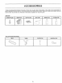
ACCESSO
THESE ACCESSORIES WERE AVAILABLE WHEN THE TILLER WAS PURCHASED. THEY ARE ALSO AVAILABLE AT
MOST SEARS RETAIL OUTLETS, CATALOG AND SERVICE CENTERS. MOST SEARS STORES CAN ORDER REPAIR
PARTS FOR YOU WHEN YOU PROVIDE THE MODEL NUMBER OF YOUR TILLER.
ENGtNE
SPARK PLUG
TILLER
MUFFLER
A_R FILTER
GAS CAN
ENGKNE OIL
STABMLIZER
iVlAJNTENANCE
BELT
TINES
CLEVIS PiN
5
HAiRPiN CLIP
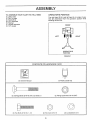
ASSE
TO ASSEMBLE
(1)
(1)
(1)
(2)
(1)
(1)
(t)
BLY
OPERATOR'S
YOUR TILLER YOU WILL NEED:
Utility knife
Pair of pliers
Screwdriver
1/2" wrenches
Ratchet
Socket extension
1/2" socket
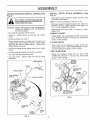
POS_TtON
The right hand (R.H.) and left hand (LH.) sides of your
tiller are determined from the operator's position while
standing behind tiller,
FRONT
LEFT
RIGHT
OPERATOR'S
POStTION
FIGURE 1
CONTENTS
OF HARDWARE
PACK
(t) Owner's Manual
(!) Plastic Cable Clip
(_'
(2) Flange Locknuts 5116-18 UNC
(2) Carriage Bolts 5/16o18 UNC x 2o3/8 Gr, 5
(2) Hex Bolts 5/I 6_t8 x 1-i/4
(2) Hex Nuts 5/t 6ol 8
6
(2) Lockwashers 5/16
ASS
LY
UNPACK CARTON & INSTALL HANDLE (See
Fig. 2)
iNSTALL
Fig. 3)
DEPTH
STAKE
ASSEMBLY
(See
• insert stake support between engine bracket halves
with stake spring down.
WHEN HANDMNG OR DISPOSING OF
BE
CAREFUL MATERIAL
OF EXPOSED STAPLES
CARTONENG
CAUTION:
NOTE: Jt may be necessary to toosen nut "A".
. Bolt stake support to engine brackets with bolts, lockwashers and nuts, Tighten securely. Also tighten nut
"A" if it was necessary to toosen.
WHEN UNPACKING AND ASSEMBLING
TILLER, BE CAREFUL NOT TO STRETCH
OR KINK CABLES.
• Depth stake must move freely. If it does not, loosen
support bolt.
° Cut cable ties securing handle column,
• Slowly lift
mount.
HANDLE
handie column up and slip over handle
o Handle height may be adjusted to better suit operator
(See "HANDLE HELGHT" in Service and Adjustments
section of this manual),
o Remove packing from carton.
• Secure hand{e column to handle mount using two (2)
carriage bolts and (2) flange locknuts, insert plastic
cable clip into hole in handle column. Tighten both
flange Iocknuts securely,
TILLING
WIDTH
. Tilling width may be adjusted to better handle your
tilling conditions (See "TINE ARRANGEMENT" in Service and Adjustments section of this manual).
• Route clutch cable through plastic cab;e clip on handle
column.
TINE
• Remove packing material from handle assembly.
. Cut cable ties securing tiller to skid,
• Cut away carton.
backwards.
HEIGHT
OPERATION
, Check tine operation before first use (See "TINE
OPERATION CHECK" in Service and Adjustments
section of this manual),
Remove tilter from skid by pulling
ENGINE
,BRACKET
HALVES
TINE CONTROL
HANDLE MOUNT\
STAKE
SPRING
TINE
CONTROL
\
O OLO
\ \
F/
DEPTH
STAKE
HEX BOLTS
LOCK WASHERS
AND HEX NUTS
FiG. 3
\
CARRIAGE
BOLT
FLANGE
LOCKNUT
FIG, 2
7
SUPPORT
BOLT
OP RATHON
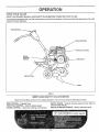
KNOW YOUR
TILLER
READ THIS OWNER'S
MANUAL AND SAFETY RULES BEFORE OPERATING YOUR TILLER.
Compare the i]Iustrationswith your tiiter to familiarize yourself with the location of various controls and adjustments. Save this
manual for future reference.
TINE CONTROL
THROTTLE
CONTROL
FiG. 4
MEETS ANSI SAFETY
REQUIREMENTS
Sears front tine tillers conform to the safety standards of the American National Standards Institute,
']'INF. CONTROL o Engages tines.
THROTTLE CONTROL - Controls engine speed,
CHOKE CONTROL - Used when starting a coJd engine,
DEPTH STAKE - Controls forward speed and the depth at
which the tiller will dig.
RECOIL STARTER HANDLE - Used to start the engine,
8
OPERATION
The operation of any tiller can result Jn foreign objects thrown into the eyes, which can
resutt in severe eye damage,
Atways wear safety glasses or eye shiellds before startir_g
your titier and while tilling. We recommend wide vision safety mask for over the spectacles
or standard safety glasses,
HOW TO USE YOUR
STOPPING
TILLER
TiLLiNG
(See Fig. 5)
The speed and depth of tilling is regulated by the position
of the depth stake and wheel height.
TINES -
, Move throttle control to "STOP" position,
The depth stake should always be below the wheels for
digging, tt serves as a brake to slow the titler's forward
motion to enable the tines to penetrate the ground. Also,
the more the depth stake is lowered into the ground the
deeper the tines will dig.
, Never use choke to stop engine.
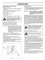
DEPTH STAKE (See Fig. 6) -
• Retease tine control to stop movement.
ENGINE -
TINE CONTROL
"OFF"
Adjust depth stake by removing the hairpin clip and clevis
pin. Change depth stake to desired position. Replace the
clevis pin and hairpin clip.
POSITION
o For normal tilling, set depth stake at the second or third
hole from the top.
WHEELS (See Fig. 6) Adjust wheels by removing the hairpin clip and clevis pin.
Change wheel position. Replace the hairpin clip and clevis
pin.
, For normal tilling, set wheels at the second or third hole
from the top.
HAIRPIN CLIP
AND CLEVIS PIN
TINE CONTROL
"RUNNING"
POSiTiON
CHOKECONTROL
THROTTLECONTROL
FiG, 6
FIG, 5
TINE OPERATION
(See Fig. 5)
Start engine and move throttie control to desired speed.
• Squeeze tine control to handle.
9
OPERATION
TRANSPORTING
YOUR
TILLER
ADD GASOLINE
AROUND THE YARD o Tip depth stake forward until it is held bythe stake spring
(See Fig. 6).
• Push tiller handles down, raising tines off the ground.
•Fiil fuel tank. Use fresh, clean, regular unleaded gasoline. (Use of leaded gasoline wil! increase carbon and
lead oxide deposits and reduce valve life.)
IMPORTANT:
• Push or pull tiller to desired location.
AROUND TOWN o Disconnect spark plug wire.
, Drain fuel tank.
Transpor_ in upright position to prevent oil leakage.
lng, allow tiller engine and muffler to
CAUTION:
Beforespark
liftingplug
or wire.
transportcoolo Disconnect
Drain
gasolir_e from fue_ tank,
BEFORE
STARTING
FILL ENGINE
WiTH
ENGmNE
WHEN OPERATING
IN TEMPERATURES 8ELOW32°F (0°C), USE FRESH,
CLEAN WINTER GRADE GASOLINE TO
HELP INSURE GOOD COLD WEATHER
STARTING.
WARNING:
Experience indicates that alcohol blended
fuels (called gasohol or using ethanol or methanol) can
attract moisture which leads to separation and formation of
acids during storage. Acidic gas can damage the fuel
system of an engine while in storage. To avoid engine
problems, the fuel system should be emptied before storage of 30 days or !onger. Drain the gas tank, start the
engine and tet it run until the fuel lines and carburetor are
empty. Use fresh fuel next season. See Storage section
of this manual for additional information. Never use engine
or carburetor cleaner products in the fu e! tank or permanent
damage may occur.
OiL (See Fig, 7)
J[,,,!PORTANT: BE VERY CAREFUL NOT TO ALLOW
DIRT TO ENTER THE ENGINE WHEN
CHECKING OR ADDING OIL OR FUEL.
USE CLEAN SAE 30 OR 10W30 WE IG HT
O1LAND STORE tN APPROVED, CLEAN,
COVERED CONTAINERS.
ALL OILS
MUST MEETA.PJ0 SERVICE CLASSIFI_
CATION SD, SE OR SF. USE CLEAN
FILL FUNNELS.
filler neck. Do not ovetf'ilL Wlpe off any
spi!_ed
CAUTION:
oit or Fill
fuel to Do
bottom
not store,
of gas
spill
tank
or
use gasoline near an open flame.
TO START
ENGINE
(See Fig, 8)
• With engine level, remove engine oii filler plug.
• Fill enaine with oil to point of overflowing. For approximate capacity see PRODUCT SPECIFICATIONS on
page 3.
• Tilt tiller back on its wheels and then reqevel.
o Check oil level. Refill to point of overflowing if necessary.
Replace oit filler plug.
o For cold weather ope,ration you should change oi! for
easier starting (See OiL VISCOSITY CHART in the
Maintenance section of this manual).
o To change engine oil, seethe Maintenance section in this
manual.
CAUTION:
"OFF" positionKeep
when
the starting
tine control
engine.in
- Make sure spark plug wire is properly connected.
, Place throttle control in "FAST" position.
- Place choke control in "CHOKE" position if the engine is
cold. A warm engine may not require choking to start.
Grasp starter handle with one hand and grasp the tiller
with other hand. Pull rooe out slowly until engine reaches
start of compression cycle (rope will pull slightly harder at
this point).
• Pulp rope with a rapid, continuous, full arm stroke. Keep
a firm grip on starter handle and let rope rewind slowly.
Do not let starter handle snap back against starter.
• When engine starts, slowly move choke control on engine halfway between "CHOKE" and "RUN" positions
and then to "RUN" position as engine warms up.
o Move throttle control to desired running position.
• Allow engine to warm up for a few minutes before
engaging tines.
NOTE: If at a high altitude (above 3000 feet) or in cold
temperatures (below 32°F), the carburetor fue! mixture
may need to be adjusted for best engine performance. See
the engine manual packed with your unit.
OIL
FILLER
PLUG
OPERATIC
SPARK
PLUG
results. When tilling in the fall, remove vines and long
grass to prevent them from wrapping around the tine
shaft and slowing your tilling operation.
o You wilt find tilling much easier if you leave a row untilled
between passes, Then go back over the entire area at
right angles (See Fig, 9), There are two reasons for doing
this, First, wide turns are much easier to negotiate than
about-faces. Second, the tiller won't be pulling itself, and
you, toward the row next to it.
CHOKE
THROTTLE
CONTROL
o Set depth stake and wheel height for shallow tilling when
working extremely hard soil or sod. Then work across the
first cuts at normal depth.
RECOIL STARTER
HANDLE
FIG, 8
BREAKING
mNYOUR
TILLER
f
Break-in your belts, pulleys and tine control before you
actually begin tilling,
o Start engine, tip tines off ground by pressing handles
down and engage tine control to start tine rotation. Allow
tines to rotate for five minutes,
• Check tine operation and adjust if necessary, See "TfNE
OPERATION CHECK" in the Service and Adjustments
section of this manual.
TILLING
FIG. 9
CULTIVATING
HINTS
Cultivating is destroying the weeds between rows to prevent them from robbing nourishment and moisture from
the plants. At the same time, breaking up the upper layer
of soil crust will help retain moisture in the soil. Best
digging depth is 1" to 3",
are accustomed to
handling your tiller,
actual field
use with throttle in slow position (midand IDLE").
CAUTION:
start_
way betweenUntiiyou
"FAST ....
• You will probably not need to use the depth stake,
Begin by tipping the depth stake forward until it is held
by the stake spring.
, Place throttle control in slow position (midway between
"FAST" and "IDLE"). Cultivate up and down the rows at
a speed which will allow Tines to uproot weeds and
leave the ground in rough condition, promoting no
further growth of weeds and grass (See Fig, 10),
To help tiller move forward, lift upthe handles slightly (thus
lifting depth stake out of ground). To slow down the tiller,
press down on handles,
If you are straining or tiiier is shaking, the wheels and depth
stake are not set properly in the soil being tilled. The proper
setting of the wheels and depth stake is through trial and
error and depends upon the soil condition. (The harder or
wetter the ground, the slower the engine and tine speed
needed. Under these poor conditions, at fast speed the tiIier
will run and jump over the ground).
q
A properly adjusted tiller will dig with littIe effort from the
operator.
o Tilling is digging into, turning over, and breaking up
packed soil before planting. Loose, unpacked soil helps
root growth. Best tilling depth is 4" to 6". A tiller will also
clear the soil of unwanted vegetation. The decomposition
of this vegetable matter enriches the soil. Depending on
the climate (rainfall and wind), it may be advisable to till
the soil at the end of the growing season to further
condition the soil
o Soil conditions are important for proper tiIIing. Tines will
not readily penetrate dry, hard soil which may contribute
to excessive bounce and difficult handling of your tiller.
Hard soil should be moistened before tilling; however,
extremely wet soil will "ball-up" or clump during tilling.
Wait until the soil is less wet in order to actlieve the best
f_..
;.-f'h
%..y
_J
%_.F"
FiG, 10
1t
NTENANCE
MAINTENANCE
SCHEDULE
FILL IN DATES
AS YOU COMPLETE
REGULAR SERVICE
SERVICE
DATES
Check Engine Oil Level
Change Engine Oil
Oil Pivot Points
_=ae====
Inspect Spark Attester Muffler
Inspect Air Screen
Repiace Air Cleaner Cartridge
Ciean Engine Cylinder Fins
Replace Spark Plug
- Change more often when operating under 8 heavy toad or in h_ghambient temper_tureso
2 ..Service more often when operating in dirty or dusty conditions.
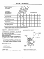
GENERAL
RECOMMENDAT!ONS
LUBRICATION
CHART
The warranty on this vehicle does not cover items that
have been subjected to operator abuse or negligence. To
receive full value from the warranty, operator must maintain unit as instructed in this manual.
Some adjustments will need to be made periodically to
properly maintain your unit.
_* ENGINE
Al! adjustments in the Service and Adjustments section of
this manual should be checked at least once each
* TINE CONTROL
season.
• Once a year you should replace the spark plug, clean or
replace air filter, and check tines and belts for wear. A
new spark plug and clean air filter assure proper air4ue!
mixture and hetp your engine run better and last longer.
BEFORE
EACH
USE
o Check engine oH level.
o Check tine operation.
o Check for loose fasteners.
* SAE 30 or IOW30 MOTOR OIL AP,_ - SFiCO
REFF_R TO ENGINE MAINTENANCE SECTION
LUBRICATION
Keep unitweillubricated
(See "LUBRICATION CHART")
12
MAINTENANCE
Disconnect spark plug wire before performing any maintenance
to prevent accidental starting of engine.
Prevent fires!
before tipping
(except carburetor
adjustment)
Keep the engine free of grass, leaves, spilled oil, or fuel. Remove fuel from tank
unit for maintenance.
Clean muffler area of all grass, dirt and debris.
Do not touch hot muffler or cylinder
fins as contact
may cause burns.
ENGINE
AIR CLEANER
LUBRICATION
Replace air cleaner cartridge every twenty-five hou rs, more
often if engine is used in very dusty conditions,
o Loosen air cleaner screws, one on each side of cover.
Change the oil after the first two hours of operation and
every 25 hours thereafter or at least once a year if the tiller
is not used for 25 hours in one year,
, Remove air cleaner cover.
Check the crankcase oii level before starting the engine
and after each five (5) hours of continuous use. Add SAE
30 motor oi! or equivalent. Tighten oiI filler plug securely
each time you check the oil level. SAE 5W-30 motor oil may
be used to make starting easier in areas where temperature
is consistently 32 ° F or lower.
• Carefully remove air cleaner cartridge. Be careful. Do not
allow dirt or debris to fall into carburetor,
•lnstali
new air cleaner cartridge.
cover. Tighten screws securely.
Clean and replace
NOTE: Do not attempt to clean or oil the paper cartridge.
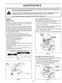
TO CHANGE ENGINE OIL (See Figs. 1! and t2) -
AiR
CLEANER
SCREW
Determine temperature range expected before oil change.
AII oil must meet API service classification SD, SE, or SF.
, Be sure tiller is on level surface,
, Oil will drain more freely when warm.
o Catch oil in a suitable container.
, Remove drain plug.
• Tip tiller forward to drain oil.
, After oil has drained completely, replace oil drain plug
and tighten securely.
• Remove oil filler plug. Be careful not to allow dirtto enter
the engine.
• Refill engine with oil, See "FILL ENGINE WITH OIL" in
Operation section of this manual.
RECOMMENDED
(See Fig. 13)
COVER
CLEANER
CARTRIDGE
SAE VISCOSITY GRADES
FZG, 13
-20°
0o
32°
60°
80°
1O0°
COOLING
(See Fig. 14)
Your engine is air cooled. For proper engine performance
and long life keep your engine clean.
• Clean air screen frequently using a stiff*bristled brush.
, Remove blower housing and clean as necessary.
• Keep cylinder fins free of dirt and chaff.
FIG. 11
OIL
DRAIN
PLUG
SYSTEM
/,
/
CYLINDER
FINS
BLOWER
/
HOUS|NG
AIR SCREEN
OIL FILLER
PLUG
OIL LEVEL
)
FiG, 12
FiG, 14
!3
MAINTE
CE
MUFFLER
TRANSMISSION
Do not operate tiller without muffler. Do not tamper with
exhaust system. Damaged mufflers or spark arresters
could create a fire hazard. Inspect periodically and replace if necessary. If your engine is equipped with a spark
arrester screen assembly, remove every 50 hours for
cteaning and inspection. Replace if damaged.
Your transmission is sealed and will not require lubrication,
SPARK
o Protect painted surfaces with automotive type wax,
CLEANING
* Clean engine, wheels, finish, etc. of all foreign matter.
, Keep finished surfaces and wheels free of all gasoline,
oil, etc.
PLUG
Replace spark plugs at the beginning of each tilling season or after every 50 hours of use, whichever comes first.
Spark plug type and gap setting is shown in "PRODUCT
SPECIFICATIONS" on page 3 of this manual.
We do not recommend us'ing a garden hose to clean your
unit unless the muffler, air filter and carburetor are covered
to keep water out. Water in engine can result in a shorte ned
engine life.
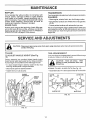
ERVlCE AND ADJUSTMENTS
r-,_A
CAUTION:
_L_
Disconnect spark pRug wires from spark plug and place wire where it cannot come into
contact with plug.
T_LLER
TO ADJUST
TINE ARRANGEMENT
HANDLE
HEIGHT
Your outer tines can be assembled in several different ways
to suit your tilling or cultivating needs.
(See Fig.
t5)
_
Factory assembly has provided highest handle height.
Select handle height best suited for your tilling conditions.
Handle height wilt be different when tiller digs into soil.
-
___
o
CAUTION:
Tines are sharp.
Wear
gloves or other protection when handling tines,
• If a lower handle height is desired, loosen the four nuts
securing handle panel to engine brackets.
• Slide handle panel to desired location,
NORMAL TILLING - 24 INCH PATH (See Fig. 16) -
• Tighten the four nuts securely,
o Assemble holes "A" in tine hubs to holes "B" in tine shaft.
CLEVISo
P,N-----tJ
ENGINE
8RACKETS
HANDLE
OUTERT N
A
A
HAIRPIN CLIP
tNNER TINE
ON LEFT SIDE
OF TILLER)
//
FIG. 16
F_Go!5
14
MID-WIDTH TiLLiNG _ 22 iNCH PATH (See Fig, t7)
F_NAL CHECK "ON" POSiTiON -
o AssembLe holes "A" in tine hubs to holes "C" in tine shaft.
o With tine control "ON" (held down to handle) push down
on handle to raise tines off the ground,
o Slowly pull recoil starter handle whib observing tines.
Tines should rotate forward,
if tines do not rotate, inner wire of control cable is too
loose. Loosen cable clip and pu!t cable up to remove
slack and retighten clip.
o Recheck in "ON" position and adjust if necessary,
NOTE: if "ON" position check required adjustment, recheck "OFF" position adjustment to insure tines do not
rotate when control is "OFF" (up).
FIG. !7
NARROW TILLING/CULTIVATING
(See Fig. 18) -
o t2-3/4
tNCH PATH
o Remove outer tines,
TINE CONTROL
/,
BODY
i
"ON" POSITION
"_
\
/
_NNER TINES ONLY
TINE
CONTROL
CABLF.
FIG. 18
NOTE: When reassembling outer tines, be sure right tine
assembly (marked "R") and left tine assembly (marked "L")
are mounted to correct side of tine shaft,
TtNE OPERATION
CHECK
(See Fig. !9)
WARNING: Disconneetsparkplug
wire
from spark ptug to prevent starting
whi_e checking fine operation.
For proper tine operation, tine control lever must be against
contro! body and aff slack removed from inner w_re of
contro_ cable when control is in the "OFF" (up) position,
if lever and cable are loose, ioosen cable clip at lower end
of cable, Pull up on cable to remove stack, without extending spring on end of cable, and retighten cabte clip.
FIG. ! 9
FINAL CHECK "OFF" POSITION o
o With tine control "OFF" (up), push down on handle to
raise tines off the ground.
o Slowly pull recoiI starter handle while observing tines.
Tines should not rotate.
o If tines rotate, inner wire of controt cable is too tight which
is extending lower spring and engaging tines. Loosen
cable clip and push down on came only enough to relieve
spring tension. Tighten cable clip.
o Recheck in "OFF" position and adjust if necessary.
15
SERVICE AN
TO REPLACE
V-BELT
ADJUSTMENTS
BELT REPLACEMENT
(See Fig. 20)
Replace V-belt if it has stretched
shows cracks or frayed edges,
considerably
- tnsta{i new V-belt to engine pulley first then to transmission pulley. Be sure belt is positioned on inside
groove of both pulleys, inside all belt guides and rests
on idler pulley,
or if it
Belt guard must be removed to service belt. See "TO
REMOVE BELT GUARD" in this section of this manual.
CHECK TINE OPERATION
-
- See "TINE OPERAT!ON CHECK" in this section of this
manual.
BELT REMOVAL ,, Remove V-belt from transmission
from engine pulley°
-
pulley first and then
REPLACE BELT GUARD
BELT
GUARD
BOLT
!
- TRANSMISSION
PULLEY
ENGINE PULLEY
BELT
\
GUIDE
_
iDLER PULLEY
FiG. 20
TO REMOVE
BELT GUARD
(See Fig, 21)
• Remove cap nut and washer from side of belt guard.
• Loosen (do not remove) tine shield nut on underside of
tine shield and cap nut on top of belt guard.
° Pull belt guard out and away from unit.
o Replace belt guard by reversing above procedure. Be
sure slot in bottom of belt guard is under head of tine
shield bolt and all nuts are tightened securely.
16
V-BELT
SERVICE AND ADJUSTMENTS
ENGINE
TO ADJUST
CARBURETOR
(See Fig. 22)
THROTTLE LtNK,.AGE
The carburetor has been preset at the factory and adjustment should not be necessary. However, minor ado
justments may be required to compensate for differences
in fuel, temperature, altitude or load. If the carburetor
does need adjustment, proceed as follows.
THROTTLE STOP
In general, turning the needle valve in (clockwise) decreases the supply of fuel to the engine giving a leaner
fuel/air mixture. Turning the needte valve out (counterclockwise) increases the supply of fuel to the engine
giving a richer fuel/air mixture.
IMPORTANT:
PRELIMINARY
DAMAGE TO THE NEEDLES AND THE
SEATS IN CARBURETOR
MAY RESULT iF SCREWS ARE TURNED tN
TOO TIGHT_
NEEDLE VALVE
FIG. 22
SETTING -
FOR PROPER ENGINE SPEED. OVERSPEEDING THE ENGINE ABOVE THE
FACTORY HiGH SPEED SETTING CAN
BE DANGEROUS. IF YOU THINK THE
ENGINE-GOVERNED
HiGH SPEED
NEEDS ADJUSTING, CONTACT YOUR
NEAREST SEARS SERVICE CENTER,
WHICH HAS PROPER EQUIPMENT
AND EXPERIENCE
TO MAKE ANY
NECESSARY ADJUSTMENTS.
, Air cleaner assembly must be assembled to the carburetor when making carburetor adjustments.
* With engine off, turn needle valve in (clockwise) c)osing it finger tight and then turn valve out (counterclockwise) 1-1/2 turns.
FINAL ,SETTING • Start engine and allow to warm for five minutes, Make
final adjustments with engine running and gearshift control lever in "NEUTRAL" position.
IDLE RPM ADJUSTMENT
, To adjust idle RPM, rotate throttle linkage counterclockwise and hold against stop while adjusting idle speed
adjusting screw to obtain 1750 RPM. Release throttle
linkage.
ACCELERATION TEST * Move throttle control lever from "SLOW" to "FAST"
position. If engine hesitates or dies, turn needle valve
out (counterclockwise) 1/8 turn. Repeat test and continue to adjust, if necessary, until engine accelerates
smoothly.
High speed stop is factory adjusted.
damage may result.
IMPORTANT;
Do not adjust or
NEVER TAMPER WITH THE ENGtNE
GOVERNOR, WHICH IS FACTORY SET
17
ENGINE
immediately prepare your tiller for storage at the end of
the season or if the unit wilt not be used for 30 days or
more.
OIL
Drain oil (with engine warm) and replace with clean oil
(See "ENGINE" in the Maintenance section of this man°
ual).
CAUTION: Never store the tiller with
gasoline in the tank inside a build=
_ng where fumes may teach an open
flame or spark. Allow the engine to
cool before storing Jn any enclosure.
CYLINDERS
Remove spark plug.
o Pour one ounce of oil through spark plug hole into
cylinder.
TILLER
* Pul! starter handle s!owty severat times to distribute oi!.
° Clean entire tiller (See "CLEANING" in the Maintenance
section of this manua0°
, Replace with new spark plug.
o Inspect and replace belts, ff necessary (See belt reo
pfacement instructions in the Service and Adjustments
section of this manual).
o Lubricate as shown in the Maintenance section of this
manual.
OTHER
o Be sure that all nuts, bolts and screws are securely
fastened. Inspect moving parts for damage, breakage
and wear. Replace if necessary.
o If possible, store your unit indoors and cover it to give
protection from dust and dirt.
• Touch up alt rusted or chipped paint surfaces;
lightly before painting.
, Do not store gasoline from one season to another.
• Replace your gasoline can if your can starts to rust.
Rust and/or dirt in your gasoline will cause problems.
• Cover your unit with a suitable protective cover that
does not retain moisture. Do not use plastic. Plastic
cannot breathe which allows condensation to form and
will cause your unit to rust.
sand
IMPORTANT:
ENGINE
FUEL SYSTEM
iMPORTANT:
iT IS IMPORTANT TO PREVENT GUM
DEPOSITS FROM FORMING IN ESSENTIAL FUEL SYSTEM PARTS SUCH
AS THE CARBURETOR, FUEL FILTER,
FUEL HOSE, OR TANK DURING STORAGE. ALSO, EXPERIENCE INDICATES
THAT ALCOHOL
BLENDED FUELS
(CALLED GASOHOL OR USING ETHANOL OR METHANOL) CAN ATTRACT
MOISTURE WHICH LEADS TO SEPARATION AND FORMATION OF ACIDS
DURING STORAGE. ACIDtC GAS CAN
DAMAGE THE FUEL SYSTEM OF AN
ENGINE WHILE iN STORAGE,
o Drain the fue! tank.
o Start the engine and let it run until the fuel lines and
carburetor are empty,
• Never use engine or carburetor cleaner products in the
fuel tank or permanent damage may occur,
o Use fresh fuel next season.
NOTE:
Fuel stabilizer is an acceptable alternative in
minimizing the formation of fuel gum deposits during storage, Add stabilizer to gasoline in fuel tank or storage
container. Always foltow the mix ratio found on stabilizer
container. Run engine at least t0 minutes after adding
stabilizer to allow the stabilizer to reach the carburetor.
Do not drain the gas tank and carburetor if using fuel
stabilizer.
t8
NEVER COVER TILLER WHILE ENGINE AND EXHAUST AREAS ARE
STILL WARM.
TROUBLESHOOTI
G
PROBLEM:
Probable Cause _r. Possible Remedy
WILL NOT START
No gasoline in Fuel Tank
Choke not set properly _Throttle Control not set properly wChoked improperly, flooded Engine _r
Dirty Air Cleaner
Loose Spark Piug Wire
Spark Plug dirty or improper gap
Water in gasoline or 01dfuel _Improper Carburetor adjustment _,Clogged Fuel Tank _-
ENGINE
Fill tank with gasoline
Place Choke Control in "CHOKE" position
Place Throttle Control in "FAST" position
Move Choke control to "Run" position, place Throttle Control in
"FAST" position and pull Starter several times to clear out gas
Remove to inspect; replace if dirty.
Make sure Spark Plug Wire is seated properly on Spark Plug
Replace Spark Ptug and adjust gap
Drain Fuel Tank and Carburetor, use fresh fuel and replace Spark
Plug
Make necessary adjustments
Remove and clean
MISSES
Engine overloaded
Partially plugged Air Cleaner
Dirty Air Screen
Spark Plug dirty, improper gap or wrong type
Oilingasoline
Improper Carburetor' adjustment
Clogged Fuef Tank
Poor compression
OR LACKS
Set Depth Stake and Wheels for shallower tilling
Remove and clean or replace
Clean Air Screen
_-
Replace Spark Plug and adjust gap
Drain and refill Gas Tank and Carburetor
__-
Low oil level or dirty oil _rDirty Air Screen
Dirty Engine
Partially Plugged Muffler _improper Carburetor adjustment
Make necessary adjustments
Remove and clean
Major Engine overhaul
OVERHEATS
Add or change oil
Clean Air Screen
Clean Cylinder Fins, Air Screen and Muffler area
Remove and clean Muffler
Adjust Carburetor to richer position
BOUNCE
Wheels and Depth Stake incorrectly adjusted _
Ground too dry and hard _
AND DIFFICULT
Ground too wet .r.
UP OR CLUMPS
Wait for more favorable soif conditions
ENGRNE RUNS WELL BUT TILLER
Tine Control not engaged _pV-Belt not correctly adjusted _V-Belt off of pulleys _
RUNS WELL
Tilling too deep _
Throttle Control not properly adjusted _
Carburetor not adjusted property _
HANDLING
Adjust Wheels and Depth Stake
Moisten ground or wait for more favorable soil conditions
SOiL BALLS
ENGINE
POWER
,r
_-
ENGINE
EXCESS!VE
OR HARD TO START
WON'T
MOVE
Engage Tine Control
Check V-Belt
Check V-Beft
BUT LABORS
WHEN T_LLING
Adjust Depth Stake
Check Throttle Controt setting
Check Carburetor adjustment
19
REPAIR PARTS
5 HP TILLER
= - MODEL
NUMBER
917.298350
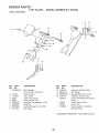
HANDLE ASSEMBLY
KEY PART
NO.
NO,
t STD533125
2
3
4
5
6
7
8
9
127768
1t0632X
3066J
2635J
23200405
t2000027
73970500
121145X
DESCRIPTION
KEY
NO.
Bolt, Carriage
5/I6-t8 UNC x 2-3/8 Gr.5
Panel, Control
Grip, Handle
Cable, Tine Control
Lever, Control, Tine
Setscrew, Hex Headless 1/4-20
Ring, Clip
Locknut, Flange 5/16_18 UNC
Clip, Cable
!0
11
I2
13
-----
PART
NO.
110512X
98000129
STD533107
110514X
t2043tX
127835
127520
12t858X
DESCRIPTION
Assembly, Handle Column
Nut, Flange
Carriage Bolt 5/16-t8 x 3/4
Assembly, Panel & Tube
Decal, Hand Placement (Control
Panel)
Decal, Control Panel
Decal, USA
Decal, Caution, Tine Control
(Control Panel)
* STANDARD HARDWARE - PURCHASE LOCALLY
2O
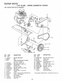
REPAIR PARTS
5 HP TILLER
- - MODEL NUMBER
917,298350
BELT GUARD AND PULLEY ASSEMBLY
8
7
\
/
8
7
.J
21
KEY
NO.
PART
NO.
1 121313X
2 9484R
3 86777
4
5
6
7
8
9
1!
12
13
14
t5
t6
t7
74770812
STD532505
121463X
104213X
STD551025
t2t612X417
72140405
9180R
23230506
9t75R
2649M
110528X
t2000036
DESCREPTtON
KEY
NO.
Bracket, Belt Guard
Clip
Screw, Hex Washer Hd. Slotted
#!0-24 x 1/2 Type D
Bolt, Hex 1/2-20 x 3/4
Carriage Bolt 1/4-20 x 1/2
Keeper, Belt
Nut, Cap 114-20
Washer 9/32 x 5/8 x 16 Ga.
Belt Guard
Carriage Bolt 1/4-20 x 5/8
V-Belt
18
19
20
21
22
23
24
25
26
27
--
Screw, Forged Socket Headless Set
Pulley, Transmission
Key, Square
Bolt, Belt Guard
Ring, Klip
* STANDARD HARDWARE - PURCHASE LOCALLY
21
PART
NO.
STD54!237
9178R
674A30
STD523712
106968X
73350500
STD541025
STD551!25
109227X
9177R
127837
DESCRIPTION
* Nut, Hex, Jam 3/8-16
Pulley, Idler
Idler Arm
* HexBolt3i8-16x
i-1/4
Shaft, !dler Arm
Nut, Hex, Jam 5/16-18
* Nut, Hex 1/4-20
* Washer, Lock 1/4
Pad, Idler
Engine Pulley
Decal, Belt Guard
REPAIR PARTS
5 HP "TILLER ° ° MODEL
NUMBER
917,298350
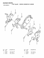
WHEEL AND DEPTH STAK5 ASSEMBLY
9
J
It
10
3
1
2
12
5
,4
21
o
,
16
5
4
18
!7
20
20
1
18
17
KEY
NO.
1
2
3
4
5
6
7
8
9
i0
1!
PART
NO.
9194R
7460520
STD523107
STD54103I
STD551131
STD6237t5
4921H
I952J
122233X
326J
STD541537
*
*
*
*
*
16
DESCRIPTKON
KEY
NO.
Pin, Clevis
Bolt, Hex 5/!6-18x
lq/4
Bolt, Hex 5/I6-18 x 3/4
Nut, Hex 5/16-t8
Washer, Lock 5/16
Bolt, Hex 3/8-24 x lq/2 Gr.5
Ctip, Hairpin
Support, Depth Stake RH
Depth Stake
Pin, Clevis
Nut 3/8-24
I2
13
t4
t5
!6
17
18
!9
20
21
PART
NO.
74760524
1951J
5388J
120958X
t2t 117X
I27832
STD551037
9t90R
STD541437
74760516
DESCRIPTION
Bolt, Hex 5/16q8 x 1ol/2
Support, Depth Stake LH
Spring, Stake
Washer
BoEt, Shoulder
Wheel
* Washer i3/32x t3/16x 11 Ga.
Bracket, Whee!
* Nut, Crownlock 3/8ot6
Bolt, Hex 5/I6oi8 x t
* STANDARD HARDWARE
22
o PURCHASE LOCALLY
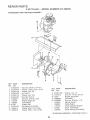
REPAIR PARTS
5 HP TILLER
.. - MODEL NUMBER
917,298350
TINE ASSEMBLY
/
4
6
!
6
5
KEY
NO,
1
2
3
PART
NO.
674A66
3146R
674A64
DESCRIPTION
KEY
NO.
Tine, Outer RH
Clip, Hairpin
Tire,e, h°_nerRH
4
5
6
23
PART
NO.
DESCRIPTRON
674A63
674A65
4929H
Tine, _nner LH
Tine, Outer LH
Pin, Clevis
REPAIR PARTS
5 HP TRLLER ° ° MODEL
NUMBER
917,298350
16
5
6
5
9
KEY
NO,
1
2
3
4
5
6
7
8
9
10
tl
12
13
DESCRIPTION
PART
NO.
STD623732
STD551037
STD55!137
STD541537
STD55! t3t
STD541031
74760544
110519X
105397X
9173R
STD54t431
19091412
19092016
*
*
*
*
*
*
Bolt, Hex 3/8-24 x 3-!/4 Gr,5
Washer '13/32 x 13/t6 x tl Ga.
Washer, Lock 3/8
Nut 3/8-24
Washer, Lock 5/16
Nut, Hex 5/!6-i8
Bolt, Hex 5/16-I8 x 2-3/4
Bracket, Engine LH
Transmission
Spacer, Split
* Nut, Keps 5/t6-18 UNC
Washer 9/32 x 7/8 x 12 Ga,.
Washer 9/32 x 1-1/4 x I6 Ga.
KEY
NO.
!4
I5
16
17
t8
---°
---
PART
NO.
STD551!25
74610412
t949J
9056R36!
74760524
!27834X
t23081X
1 t07t9X
127836
120075X
DESCRIPTION
Washer, Lock t/4
Bolt, Hex I/4-28 x 3/4 Gr,5
Bracket, Engine RH
Tine Shield
Bolt, Hex 5/16-!8 x 1-1/2
Manual, Owner's
Decal, Engine
Decal, Operation (Engine)
Decal (-Fine Shield)
Decal, Warning (Tine Shield)
* STANDARD HARDWARE ° PURCHASE LOCALLY
24
REPAIR PARTS
5 HP TILLE:R - - MODEL NUMBER 917.298350
ENGINE - - BRIGGS
& STRATTON,
MODEL NO. t 30202, "TYPE NO. 3256-01
7
33
3O
36
7'41
230
m l_-fgl_k
i
_PNR L_TION
" t,_N'dAL
Assemblies
inctude aH pars
25
shown in frames.
REPAIR PARTS
5 HP TMLLER - = MODEL NUMBER 917.298350
ENGINE - - BRIGGS & STRATTON, MODEL NO. 130202, TYPE NO. 3256-01
527
529
190
_
209
191
1I
.536
526
916
/
!24
Assemblies
include atl parts shown in frames,
26
621
REPAIR PARTS
5 HP TILLER = = MODEL NUMBER 9!7.298350
ENGINE o - BRIGGS & $TRATTON, MODEL NO. 130202, TYPE NO. 3256°,01
24
74
U
@
373
G
!
346
37
Assemblies include aH parts shown in frames.
27
200
REPAIR PARTS
5 HP TILLER
ENG1N5 =- 8RIGGS
REF.
NO.
PART
NO.
1
2
395990
297585
Note:
3
5
299819
211542
7
8
• 272157
294178
9
10
* 27549
93394
11
66578
12
• 270080
270! 25
270125
!3
94221
14
93369
15
94387
Note:
t6
397103
Note:
& STRATTON,
DESCRIPTION
Cylinder Assembly
Bushing-Cylinder
Requires Special Tools
for Installation.
Seal-Oil
Head-Cylinder
Screw-Breather
Mtg.
Sere
Grommet-Breather
Tube
Gasket-Crankcase-
To Replace Crankshaft
Gear Pin, Order Part
No. 230978.
Cover Assy.Crankcase
19
297603
Bushing--Crankcase
Cover
294506
66768
22
93032
Requires Special Tools
for Installation.
Seal--Oil
297229
222698
298904
298905
298906
298907
28
PART
NO.
DESCRIPTION
298982
Ring Set-Standard
Piston
298983
Ring Set-.010"
Piston
298984
Ring Set-°020 _ O.S.
Piston
O.S.
Ring Set-.030" O.S.
Piston
26026 Lock-PistonPin
298909
Pin Assy.-PistonStandard
298908
Pin Assy.-Piston.005" O,S.
299430
Note:
Rod Assy.-Connecting
For Connecting Rod
with .020" undersize
REF.
NO.
PART
NO.
66
399671
Clutch Assy.-Rewin
Starter
67
68
394897
63770
70
71
298799
394506
Housing-Starter
BaIF_lutch
Ratchet-Rewind
73
74
75
81
90
95
221923
93490
224061
222263
492611
93499
96
97
223793
490048
t08
118
124
127
127A
191
e 272410
200
223886
201
202
203
204
262280
262270
280720
222962
205
208
209
231520
262279
262283
32
33
34
92296
211119
261044
Screw-Connecting
Valve-Exhaust
Valve-Intake
153
154
35
36
37
40
45
46
260552
26478
222443
93312
260642
212733
Spring-Intake
Valve
Spring-Exhaust
Valve
Guard-FIy'whee]
Retainer-Valve
Spring
Tappet-Valve
Gear-Cam
52
_271936
295871
Rod
Gasket-Carburetor
Pulley-Rewind
Starter
(includes 63 _ Long
Rope)
57
58
59
60
490179
56884
490653
490652
65
94128
Spring-Rewind
Starter
Ropeq%wind
Starte
Insert-Starter Handle
Handle-Rewind
Starter
Screw-Stamped
Steel
Housing _g. Sere
28
Washer-Spring
LocK-Screw
Carburetor Assembl
Screw-Throttle Valv
Shaft Sere
Throttle-Carburetor
Shaft and LeverThrottle
492927
490075
94094
149
152
299431
St_
Washer-Clutch
Retainer
Screen-Starter Pu]l_
Scre,_-Hex, Head
180
18!
190
Dipper-Connecting
Rod
Lock-C_nn.
Rod Screw
55
CIt
163
221890
221876
Mounting (2)
Housing-Rewind
Starter
DESCRIPTION
491177 Valve Group-Chok_
23t 533 Valve-Needle
93357 Screw-Hex, Head
220352 Plug-Welch
223789 Plug-Welch
(Mixing Chamber)
26336 Spring-Needle VaN
250575 Spring-Throttle
Adjustment
490589 Screw Assy.
93527 Screw-Machine,
Rc
Hd.-5-40 x 5/8"
271935 Gasket-Air Cleaner
30
31
Sam
Ftywhee#Magneto
Key--Flywheel
Piston Assy.-Standard
Piston Assy.-.010= O.S.
Piston Assy_-.020= O.S.
Piston Assy.-.030" O.S.
Included in Gasket SetPart No. 397145.
MODEL NO. 130202, TYPE NO. 3256-01
Crankpin Bore-Order
No. 390459.
55
Ptug-Oil Filler
Screw-Crankcase
Cover Mounting
23
24
25
27
29
Screw-Cylinder
Head
(2-3/32" long)
Screw-Cylinder
Head
(2-15/32" long)
Plug--Pipe
93448 Plug-Pipe
(Hex. Socket)
Crankshaft
9t7.298350
298985
.015" Thick (Standard)
Gasket-Crankcase.005" Thick
Gasket-Crankcaseo00g" Thick
NUMBER
.PISTON RING SETS:
Note: For Chrome Piston
Ring Set -Standard
Size --Order Part No.
299742.
Gasket--Cylinder Head
Breather-Valve
Chamber
Gasket-Valve
Cover
297602
20
21
REF.
NO.
25
18
Note:
o o MODEL
Mounting
Tank Assembiy-Fu_
Cap-Fuel Tank
Screw-Fuel Tank
Mounting Sem
Gasket-Fuel Tank
Mounting
Guide-Air
Link-Govemor
Link-Throttle
Crank-Bell
Bushing-C_vemor
Lever
(Fiat)
Screw-Shouk{er
Rod-C_ntrol
Spring-Governor
REPAIR PARTS
5 HP TILLER =- MODEL NUMBER 917.298350
ENGINE o = BRtGGS & STRATTON, MODEL NO. 130202, TYPE NO. 3256-01
REF.
NO.
PART
NO.
216
219
220
222
223
262359
391737
221551
490649
223455
224
93491
DESCRIPTION
Link-Choke
Gear-Governor
Washer-Thrust
Bracket-Control
Lever-Governor
Control
Rivet-Governor
Control
REF.
NO.
PART
NO.
414
220982
432
433
434
435
221377
93265
210959
93141
467
525
527
528
529
223786
231550
87838
227
230
490374
222450
256
300
223813
393515
Crank-BeB
Muffler-Exhaust
304
305
49016£
93158
Housing-Blower
Screw-Blower
Housing
536
542
494279
93572
552
231079
306
307
221511
93490
308
333
335
221512
397358
93414
33'1
346
356
358
802592
93705
398808
397145
Mtg. Sere
Plug-Spark
Screw-Sere
Wire-Ground
Gasket Set
363
19069
373
92987
Flywheel Puller
(Optional Accessory)
Nut-Hex.
383
392
89838
262328
Wrench-Spark
Plug
Spdng-Fuej
Pump
394
270026
Diaphragm
Diaphragm
]nctuded in Gasket SetPart No. 397145.
Washer
Cap-Spring
Pin-Diaphragm
Cover
Cover--Diaphragm
Screw-Diaphragm
Cover
28-0715 Knob-Control
94409 Screw-Tank Bracket
Lever Mounting
Lever Assy.-4Governor
Washer-Governor
Lever
Mounting
SMeld-Oylinder
Screw-43ylinder Shield
Mounting Sere
Cover-CyIinder
Head
Armature AssemMy
Screw-Armature
DESCRtPT!ON
Mounting Sere
Clamp-Breather
Tube
Tube-Breather
Grommet-Breather
Tube
Air Cleaner Kit
Screw
Bushing-43overnor
Crank
REF.
NO.
PART
NO.
655
676
222598
393757
679
270382
680
221839
Washer Choke Shaft
741
779
261596
262276
(Brass)
Gear-Timing
Link-Bell Crank
851
869
221798
211787
Cable Terminal-lgnitbn
Seat-lntake Valve
870
211172
(Standard)
Seat-Exhaust
Bolt--Governor
Nut-Hex,-!0-24
608
81!
390463
391813
6t3
93935
614
93306
Starter Assyo-Rewind
Fuel Pipe and Clip
Assembly
Screw-Hex. Hdo
Shoulder
Cotter-Hair Pin
615
516
93307
231077
Retainer-E-Ring
Crank-Governor
396847
271853
(1/4" Dia,)
Switch-Stop
Washer-Throttle
821
634
835
66538
(Foam)
Elbow-Spark
Note:
29
231348
Note:
Lever
Shaft
Plug
Washer Choke Shaft
(Foam)
871
92613
231082
Anchor Spring
Deflector-Exhausl
(Side Outlet)
(1/4"I.D.)
562
592
DESCRIPTION
Valve
(Standard)
For Options see Repair
Manual.
Guide-Exhaust
Vaive
83709 Guide-Intake
Valve
See Repair Instruction
Manual
916
966
987
968
280321
490074
491588
223765
Gear Rack-Governor
Base-Air Cleaner
Fiker-Air
Cover Air Cleaner
969
490073
97t
987
995
1012
94018
398970
223887
490507
Screw-Cover Mtg.
(includes Grommet)
Screw-Air Cleaner
Seal-'R_rottle Sha{t
Bracket-Link
Link-Retainer
1016
1019
490817
491100
Spacer
Label Kff
SERVICE
30
OTES
RVICE
31
OTES
®
OWNER'S
MANUAL
5.0 HP
24
CH Tm E WIDTH
FRONT T! E TULLE
MODEL NO.
917.298350
Each tiller has its own model number.
number.
Each engine has its own model
The model number for your tiller will be found on a plate attached to the
right hand engine bracket,
The model number for your engine wil! be found on the blower housing of
the engine adjacent to the spark plug,
All parts listed herein may be ordered from any Sears, Roebuck and Co.
Service Center and most Retail Stores,
HOW TO ORDER
REPAIR PARTS
WHEN ORDERING REPAIR PARTS, ALWAYS
ING INFORMATION;
GIVE THE FOLLOW-
PRODUCT _ FRONT TlNE TILLER
• MODEL NUMBER - 9t7.298350
, ENGINE MODEL NUMBER - 130202, TYPE NUMBER 3256o01
• PART NUMBER
PART DESCRIPTION
Your Sears merchandise has added value when you consider Sears has
service units nationwide staffed with Sears trained technicians,,, professional technicians specifically trained to insure that we meet our pledge
to you, we service what we sell.
Sears, Roebuck
127834X0E
10,19.90
and Co., Chicago,
IL 60684 UoS°A.
PRINTED IN U,S,,