1
SERVICE
MANUAL
SUPPLEMENT
DIESEL
ENGINE
REAR WHEEL DRIVE
TRUCK
D& W 250-350
TYSLER
MOTTOES
DIESEL ENGINE
S E R V I C E MANUAL
SUPPLEMENT
1991 1/2 DODGE TRUCKS
To order the special service tools used and
illustrated, please refer to the instructions on
inside back cover.
NO PART OF THIS PUBLICATION MAY BE
REPRODUCED, STORED I N A RETRIEVAL
SYSTEM, OR TRANSMITTED, IN ANY FORM
OR BY ANY MEANS, ELECTRONIC, MECHANICAL, PHOTOCOPYING, RECORDING,
OR OTHERWISE WITHOUT THE PRIOR
WRITTEN PERMISSION OF CHRYSLER
MOTORS.
Chrysler Motors reserves the right to make changes in design or to make
additions to or improvements in its products wihtout imposing any obligations upon itself to install them on its products previously manufactured.
Litho in U.S.A. Copyright
©1991 Chrysler Motors
20M191
FOREWORD
The information contained in this service manual has been prepared for the professional automotive technician involved in daily repair operations. This manual does not cover theory of operation, which is addressed in
service training material.
Information in this manual is divided into groups. These groups contain general information, diagnosis, testing, adjustments, removal, installation, disassembly, and assembly procedures for the components.
To assist in locating a group title page, use the Group Tab Locator on the following page. The solid bar after
the group title is aligned to a solid tab on the first page of each group. This first page of the group has a
contents section that lists major topics within the group.
Chrysler Motors reserves the right to change testing procedures, specifications, diagnosis, repair methods, or
vehicle wiring at any time without prior notice or incurring obligation.
Information describing the operation and use of standard and optional equipment is included in the Owner's
Manual provided with the vehicle.
C 0 1 P 0 1 E 1 T A l i S Y S T E i INDEX
Name
Group-page
5.9L DIESEL ENGINES. .
. . . . 9-1
ENGINE DIAGNOSIS
9=3
ENGINE SERVICE PROCEDURES
9-12
GENERAL INFORMATION
-.9-1
AIR CONDITIONING
24-1
COMPRESSOR OVERHAUL (SD-709) . . . . . . . . 24-1
Compressor
24-2
Compressor Isolation
24-1
Compressor Shaft Seal
Cylinder Head/Valve Plate
Description
Magnetic Clutch
Purging Compressor of Air
TORQUE SPECIFICATIONS—A/C
COMPRESSOR
BRAKES............
Diesel Vacuum Pump
Installing Vacuu,—Steering Pump
Assembly
Low Vacuum Warning Switch
Pump Adapter Replacement
Removing Vacuum—Steering Pump
Assembly
Vacuum Pump
Vacuum Pump
Vacuum Pump
Vacuum Pump
COOLING SYSTEM
Diagnosis
Operation
Replacement
Serviceability
24-5
24-8
24-1
24-2
24-1
24-9
.......5-1
.5-1
5-5
5-1
5-4
5-2
5-2
5-1
5-4
5-1
7-1
SPECIFICATIONS
7-1
EMISSION CONTROL SYSTEMS
25-1
EXHAUST EMISSION CONTROLS
25-1
EXHAUST SYSTEM AND INTAKE MANIFOLD. . . . . 11-1
SERVICE PROCEDURES (DIESEL ENGINES) . . . 11-1
Exhaust Manifold
11-1
Intake Manifold Cover/Air Intake Heater
11-2
Intercooler
.11-8
Turbocharger
11-3
SPECIFICATIONS
11-9
FUEL SYSTEM
14-1
DIESEL FUEL INJECTION
14-1
Air Intake Heater Relays—Engine Controller
Output
14-4
Battery Voltage—Engine Controller Input .. . 14-2
Brake Switch—Engine Controller Input . . . . 14-2
Charge Air Temperature Sensor—Engine
Controller Input
14-2
Crank Signal—Engine Controller Input
14-2
Engine Controller
14-1
General Information
14-1
Name
Group-page
Ignition Sense—Engine Controller Input
14-2
KSB Solenoid
14-5
Overdrive Override Switchitch —Engine
Controller Input
14-2
Overdrive Solenoid—Engine Controller
Output
14-5'
Park/Neutral Switch —Engine Controller
Input
14-2
SCI Receive and SCI Transmit—Engine
Controller
Output
14-5
Speed Control—Engine Controller Input . . . . 14-3
Speed Control—Engine Controller Output ... 14-5
System Diagnosis
14-1
System Operation
14-5
Throttle Position Sensor (TPS)—Engine
Controller Input
14-3
Vehicle Distance (Speed) Sensor—Engine
Controller Input
14-3
Wait-To-Start Lamp—Engine Controller
Output
14-5
Water-ln-Fuel Lamp—Engine Controller
Output .
14-5
Water-ln-Fuel Sensor—Engine Controller
Input
14-3
GENERAL DIAGNOSIS-DIESEL
. 14-8
Air Intake Heater
14-11
KSB Solenoid
14-11
On Board Diagnostics
14-11
Throttle Position Sensor Test
14-10
Visual Inspection
14-8
SERVICE PROCEDURES
14-21
Fuel Injection Pump
14-22
Injection Timing
14-26
KSB Solenoid
14-22
Throttle Position Sensor
14-21
INSTRUMENT PANEL AND GAUGES
8E-1
SPEED CONTROL SYSTEM
8H-1
SERVICE PROCEDURES
8H-8
TEST PROCEDURES
8H-4
Checking for Fault Code
8H-4
Distance (Speed) Sensor Test
8H-4
Inoperative System
8H-4
Road Test
8H-4
Speed Control Cable Attachment—Engine .. 8H-7
Speed Control Cable Attachment—Servo ... 8H-7
Speed Control Switch Test
8H-5
Speed Control System Electrical Tests
8H-4
Stop Lamp Speed Control Switch Test . . . . 8H-5
Vacuum Supply Test
8H-6
STEERING
19-1
GENERAL INFORMATION
19-1
TRANSMISSION
21-1
Fluid Temperature Thermo-Switches
21-2
General (information
General Specifications—Diesel A518
21-1
. . . . . . 21-3
Governor Weight Assembly
Planetary Gears
21-1
—
21-1
Service Procedure And Specification
Changes
21-2
Servicing The New Overrunning Clutch . . . . 21-2
Torque Converter
21-1
Transmission And Overdrive Compounder
Clutch Packs
21-2
Transmission Case
21-1
Transmission Overrunning Clutch And
Low-Reverse Drum
21-1
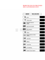
GROUP
TAB
LOCATOR
Brakes
Cooling System
8E
Instrument Panel and
Gauges
8H
Speed Control System
8W
Wiring Diagrams
Engines
d| i |
Exhaust System and Intake
Manifold
14
Fuel System
19
Steering
21
Transmission
24
Air Conditioning
25
Emission Control Systems
iH:;&"*»-.i
•
BRAKES
5- 1
B R A K E S
CONTENTS
page
DIESEL VACUUM PUMP
INSTALLING VACUUM-STEERING PUMP
ASSEMBLY
LOW VACUUM WARNING SWITCH
PUMP ADAPTER REPLACEMENT
REMOVING VACUUM-STEERING PUMP
ASSEMBLY
1
5
1
4
page
VACUUM
VACUUM
VACUUM
VACUUM
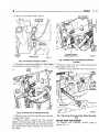
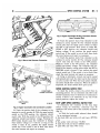
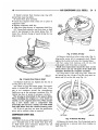
DIESEL VACUUM PUMP
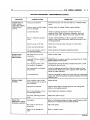
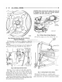
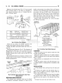
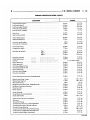
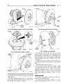
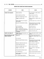
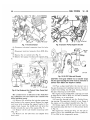
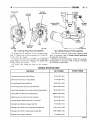
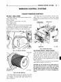
A new design power brake vacuum pump is used
on 1991-1/2 AD models with the Cummins turbo diesel engine. However, the new vacuum pump is still
combined with the power steering pump into a single
assembly (Fig. 1).
The new vacuum pump is a constant displacement,
vane-type pump. Vacuum is generated by four vanes
mounted in the pump rotor. The rotor is located in
the pump housing and is pressed onto the pump
shaft.
The vacuum and steering pumps are both operated
by a single drive gear pressed onto the vacuum pump
shaft. The drive gear is operated by . the camshaft
gear.
The vacuum and power steering pump shafts are
connected by a coupling. Each pump shaft has an
adapter with drive lugs that engage in the coupling.
The vacuum pump rotating components are lubricated by engine oil. Lubricating oil is supplied to the
pump through an oil line at' the underside of the
pump housing.
VACUUM PUMP SERVICEABILITY
The vacuum pump is not a serviceable component.
If diagnosis indicates a pump malfunction, the pump
must be removed and replaced as an assembly. Do
not disassemble or attempt to repair the pump.
The combined vacuum and steering pump assembly
must be removed for access to either pump. However,
the vacuum pump can be removed without having to
disassemble the power steering pump.
If the power steering pump requires service, simply
remove the assembly and separate the two pumps.
Refer to the pump removal and installation procedures in this section.
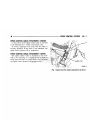
LOW VACUUM WARNING SWITCH
A vacuum switch is used to monitor output of the
vacuum pump. The switch is in circuit with the
brake warning light.
PUMP
PUMP
PUMP
PUMP
DIAGNOSIS . . .
OPERATION
..
REPLACEMENT
SERVICEABILITY
.. 2
.. 1
.. 4
.. 1
VACUUM
GEAR
ADAPTER
J9105-94
Fig.
1 Vacuum
And Steering
Pump
Assembly
A vacuum hose connects the switch to the power
brake booster. A wire harness connects the switch to
the brake warning light.
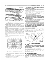
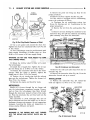
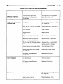
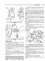
The switch is mounted on the driver side inner
fender panel just below the hood hinge (Fig. 2).
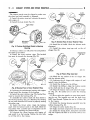
VACUUM PUMP OPERATION
Vacuum pump output is transmitted to the power
brake booster through a supply hose. The hose is connected to an outlet port on the pump housing and to
the check valve in the power brake booster.
Pump output ranges from a minimum of 8.5 to 25
inches vacuum.
The pump rotor and vanes are rotated by the pump
drive gear. The drive gear is operated by the camshaft gear.
Booster vacuum level is monitored by a warning
switch (Fig. 2). The switch consists of a vacuum
chamber that measures vacuum level and a sensor in
circuit with the brake warning light.
5 -2
•
BRAKES
Fig.
2 Vacuum
Switch
Location
The vacuum chamber is connected to the booster
check valve by a vacuum supply hose. A wire harness connects the switch sensor to the brake warning
light. If booster vacuum falls below 8.5 inches for
8-10 seconds or more, the switch sensor completes
the circuit to the warning light causing it to illuminate.
VACUUM PUMP DIAGNOSIS
Vacuum pump diagnosis involves checking pump
output with a vacuum gauge. The low vacuum warning switch can also be checked with a vacuum gauge.
Refer to the diagnosis procedure in this section.
A standard vacuum gauge can be used to check
pump output when necessary. Simply disconnect the
pump supply hose and connect a vacuum gauge to
the outlet port for testing purposes. Vacuum should
hold steady in a range of approximately 8.5 to 25
inches at various engine speeds.
DIAGNOSING
CONDITION
LOW
VACUUM
(3) Check booster operation as described in the diagnosis section. Replace the check valve, vacuum
hoses, or booster if necessary. However, if booster operation is correct but the warning light is still on,
continue testing.
(4) Disconnect the vacuum hose from the warning
switch, plug the hose and connect a hand vacuum
pump to the switch.
(5) Start and run the engine.
(6) Apply 8.5 to 9 inches of vacuum to the warning
switch and observe the warning light. If the light
goes out, the switch vacuum hose is either loose or
leaking. If the light remains on, leave the engine
running and continue testing.
(7) Apply 20-25 inches vacuum to the switch and
observe warning light operation. If the light now
goes out, the switch is at fault and should be replaced. If the light remains on, continue testing.
(8) Reconnect the vacuum hoses and replace the
original warning switch with a known good switch.
Run the engine and observe warning light operation.
If the light is now off, the old switch is faulty. If the
light remains on, the problem is in the wiring between the switch and warning light.
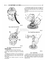
REMOVING VACUUM-STEERING PUMP
ASSEMBLY
(1)
(2)
(3)
from
Disconnect battery negative cable.
Position drain pan under power steering pump.
Disconnect vacuum and steering pump hoses
respective pumps (Fig. 3).
OUTPUT
A low booster vacuum condition or a faulty low
vacuum warning switch will cause the brake warning light to illuminate. If the light does go on and indicates the existence of a low vacuum condition,
check the vacuum pump, booster and warning switch
as follows:
(1) Check vacuum pump oil feed line. Verify that
line connections are secure and not leaking. If leakage is noted and pump is noisy, replace pump.
(2) Check vacuum pump output with a standard
vacuum gauge. Disconnect the supply hose to the
booster. Connect the gauge to this hose and run the
engine at various throttle openings. Output should
range from 8.5 to 25 inches vacuum. If vacuum is
consistently below 8.5 inches, the problem is with the
vacuum hoses or a vacuum pump component. If output is within specified limits, continue testing.
Fig.
3 Vacuum
And Steering
Connections
Pump
Hose
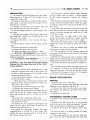
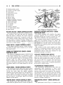
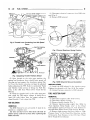
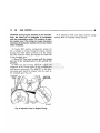
(4) Disconnect oil pressure sender wires at sender
(Fig. 4).
BRAKES
(5) Remove oil pressure sender (Fig. 4).
5- 3
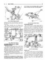
PUMP ASSEMBLY
LOWER MOUNTING
ADAPTER
BRACKET
STEERING
PUMP
Fig.
ENGINE BLOCK
4 Oil Pressure
Sender
J9119-74
BOTTOM-INBOARD
ADAPTER BRACKET NUT
Fig. 6 Adapter
Location
(6) Disconnect lubricating oil feed line from fitting
at underside of vacuum pump (Fig. 5).
J9105-97
And Pump Mounting
Location
Fastener
(9) Remove upper bolt that attaches pump assembly to engine block (Fig. 7).
(10) Remove pump assembly from vehicle (Fig. 8).
VACUUM
PUMP
VACUUM
PUMP
OIL FEED
LINE
Fig. S Oil Feed
Line
Connection
J9105-96
J9119-76
At Pump
(7) Remove lower bolt that attaches pump assembly
to engine block (Fig. 6).
(8) Remove bottom, inboard nut that attaches
adapter to steering pump (Fig. 6). This nut secures a
small bracket to engine block. Nut and bracket must
be removed before pump assembly can be removed
from block.
Fig. 7 Removing
Pump
Assembly
Bolt
Upper
Mounting
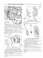
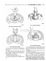
VACUUM PUMP REPLACEMENT
(1) Remove nuts attaching vacuum pump to
adapter (Fig. 8).
5 -4
BRAKES
ROTATE DRIVE
GEAR TO ALIGN
J9105-98
Fig,
8 Pump
Assembly
Removal
(2) Remove vacuum pump from adapter (Fig. 9).
Turn pump gear back and forth to disengage pump
shaft from coupling if necessary.
(3) Inspect adapter O-ring (Fig. 9). Replace O-ring
if cut or torn.
TANGS
Fig.
10 Aligning
Pump
Shaft
Drive
J9105-102
Tangs
COUPLING
O-RING
PUMP
ADAPTER
J9105-99
Fig,
9 Vacuum
Pump
Removed
From
Adapter
(4) Lubricate adapter O-ring with engine oil.
(5) Note position of drive slots in coupling. Then rotate drive gear to align tangs on vacuum pump shaft
with coupling (Fig. 10).
(6) Verify that pump is seated in adapter and coupling.
(7) Install and tighten pump attaching nuts and
washers.
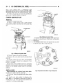
PUMP ADAPTER REPLACEMENT
(1) Remove coupling from adapter (Fig. 11).
(2) Remove remaining adapter attaching nuts and
remove adapter from steering pump (Fig. 12).
(3) If steering pump will be serviced, remove spacer
from each inboard mounting stud on pump (Fig. 12).
(4) Clean and lubricate pump shaft with engine oil.
Fig.
11 Removing/installing
Pump
Drive
Coupling
(5) Install spacers on steering pump studs (Fig. 12).
(6) Install O-ring on adapter (Fig. 11).
(7) Position adapter on pump studs.
(8) Install attaching nuts on outboard stud and on
the two upper pump studs. Do not install nut on
lower, inboard stud at this time. Tighten nuts to 24
N-m (18 ft. lbs.) torque.
(9) Install coupling on pump shaft. Be sure coupling is securely engaged in shaft drive tangs.
—
_
BRAKES
5 - 5
(2) Insert pump assembly upper attaching bolt in
mounting flange and gasket. Use sealer or grease to
hold bolt in place if necessary.
(3) Position pump assembly on engine and install
upper bolt (Fig. 14). Tighten upper bolt only enough
to hold assembly in place at this time.
Fig.
12 Steering
Pump
Mounting
Locations
Stud
Spacer
(10) Install vacuum pump on adapter. Rotate drive
gear until tangs on pump shaft engage in coupling.
Verify that pump is seated before installing attaching nuts.
(11) Install and tighten vacuum pump attaching
nuts.
INSTALLING VACUUM-STEERING PUMP
ASSEMBLY
(1) Position new gasket on vacuum pump mounting
flange (Fig. 13). Use Mopar perfect seal, or silicone
adhesive/sealer to hold gasket in place.
Fig.
13 Positioning
Gasket
Flange
On Pump
Mounting
Fig.
14 installing
Pump
Assembly
On
Engine
(4) Working from under vehicle, install pump assembly lower attaching bolt. Then tighten upper and
lower bolt to 77 N-m (57 ft. lbs.) torque.
(5) Position bracket on steering pump inboard stud.
Then install remaining adapter attaching nut on
stud. Tighten nut to 24 N»m (18 ft. lbs.) torque.
(6) Connect oil feed line to vacuum pump connector. Tighten line fitting securely.
(7) Install oil pressure sender and connect sender
wires.
(8) Connect steering pump pressure and return
lines to pump. Tighten pressure line fitting to 30
N-m (22 ft. lbs.) torque.
(9) Connect vacuum hose to vacuum pump.
(10) Connect battery cables, if removed.
(11) Fill power steering pump reservoir.
(12) Purge air from steering pump lines. Start engine and slowly turn steering wheel left and right to
circulate fluid and purge air from system.
(13) Stop engine and top off power steering reservoir fluid level.
(14) Start engine and check brake and steering operation. Verify that power brake booster is providing
vacuum assist and firm brake pedal is obtained.
Then verify that steering action is correct. Do this
before moving vehicle.
•
COOLING SYSTEM
7 -1
COOLING SYSTEM
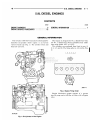
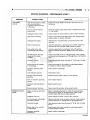
GENERAL INFORMATION
This group contains changes made to the diesel
cooling system during the mid-1991 model year. The
main change is a new higher capacity cross-flow radiator. The cooling system capacities have changed
as a result of the new radiator.
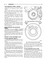
RADIATOR
A cross-flow radiator is used in the mid-1991 model
year. The radiator cools the engine and automatic
transmission (if equipped).
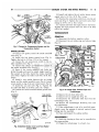
REMOVAL
(1) Disconnect battery negative cable from battery.
WARNING: DO NOT REMOVE THE CYLINDER
BLOCK DRAIN PLUGS OR LOOSEN THE RADIATOR
DRAINCOCK WITH THE SYSTEM HOT AND UNDER
PRESSURE BECAUSE SERIOUS BURNS FROM
COOLANT CAN OCCUR,
(2) Drain the cooling system. Refer to Draining
Cooling System in the 1991 Rear Wheel Drive Truck
Service Manual.
(3) Remove hose clamps and hoses from radiator.
Remove coolant reserve tank hose from radiator filler
neck nipple.
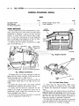
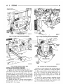
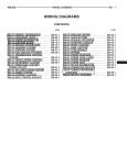
(4) Remove fan shroud retaining clips. The shroud
has two tabs that fit into clips in the bottom of the
radiator. Lift the shroud up and position it back onto
the engine (Fig. 1).
(5) Remove radiator top mounting brackets. The
brackets fit over support dowels on the radiator inlet
tank (Fig. 1).
(6) The bottom of the radiator has two dowels that
fit into holes in the lower support panel. Taking care
not to damage radiator cooling fins or tubes, lift ra-
Fig.
1 Radiator
and Fan
Shroud
diator straight up out of engine compartment.
INSTALLATION
(1) Position shroud rearward on engine.
(2) Lower radiator into position. The dowels on the
bottom of the radiator fit into alignment holes in the
lower support panel.
(3) Install top mounting brackets. Tighten mounting screws to 23 N»m (17 in. lbs.) torque.
(4) Connect radiator hoses. Install hose clamps.
(5) Position fan shroud on radiator flange. Install
retaining clips.
(6) Open heater valve.
(7) Fill cooling system with coolant. Refer to Filling Cooling System in the 1991 Rear Wheel Drive
Truck Service Manual.
(8) Operate engine until i t reaches normal temperature. Check cooling system.
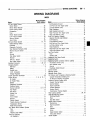
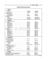
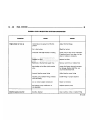
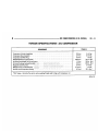
SPECIFICATIONS
COOLING
SYSTEM
CAPACITIES
IMINI
MOML
Diesel
All
Diesel
All
A
m
•
WIDTH I H K K INCHES NISS
CAPACITY
FAN
RADIATOR
ROWS HNS
OF
MR
TUBES INCH
DIAMETBR
INCHES
CLWTCH
NO. OP PITCH •NOAOIMINT
BLADES INCH T1MMRATURI
QUARTS
units
26
2.25
3
13
22.0
7
2.20
140°F
17.0
16.1
26
2.25
3
13
22.0
7
2.20
140 °F
16.0
15.1
39107 881
•
INSTRUMENT PANEL AND GAUGES
8E - 1
INSTRUMENT PANEL AND GAUGES
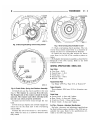
OWERDRIWE LOCKOUT SWITCH
INSTALLATION
REMOVAL
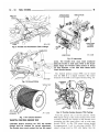
(1) Locate bracket holding chime module and intermittent wipe module (Fig. 2).
(2) Remove 2 nuts holding bracket to instrument
panel support.
(3) Remove ground straps and bracket.
(4) Depress lock tabs on switch and push i t out of
the instrument panel.
(1) Hold wiring connector in switch opening.
(2) Push switch on to wiring connector.
(3) Continue to push until switch snaps into place.
(4) Install bracket with modules. Be sure ground
straps are installed.
GROUND
COMBINATION
BUZZER
INTERMITTENT
WIPER MODULE
BRACKET
INTERMITTENT WIPER
CONTROL MODULE
J918E-37
Fig.
1 Overdrive
Lockout
Switch
Location
J918E-36
Fig. 2 Intermittent
Wiper
Module
Bracket
•
SPEED CONTROL SYSTEM
8H - 1
SPEED CONTROL SYSTEM
CONTENTS
page
SERVICE PROCEDURES
8
GENERAL INFORMATION
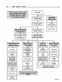
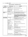
The speed control system (Fig. 1) is electrically actuated and vacuum operated. The electronic control
is integrated into the engine controller, located next
to the battery. The controls are located on the steering wheel and consist of the ON/OFF, RESUME/ACCEL and SET/DECEL buttons. The system is
designed to operate at speeds between 35 mph (50
km/h) and 85 mph (142 km/h).
page
TEST PROCEDURES
4
the vehicle to continuously accelerate and set at a
higher speed setting.
TAP-UP: When the speed control system is engaged, tapping the RESUME/ACCEL button will increase the speed setting by 2 mph (3 km/h). The
system will respond to multiple tap-ups.
TO ACCELERATE for PASSING: Depress the
accelerator as you would normally. When the pedal
is released the vehicle will return to the speed setting in memory.
WARNING; THE USE OF SPEED CONTROL IS NOT
RECOMMENDED WHEN DRIVING CONDITIONS DO
NOT PERMIT MAINTAINING A CONSTANT SPEED,
SUCH AS IN HEAVY TRAFFIC OR ON ROADS THAT
ARE WINDING, ICY, SNOW COVERED, OR SLIPPERY.
TO ACTIVATE: By pushing the ON/OFF button
to the depressed latched position, ON, the speed control function is now ready for use.
TO DEACTIVATE: A soft tap of the brake pedal,
or normal brake application while the system is engaged will disengage speed control without erasing
memory. Pushing the ON/OFF button to the unlatched position or turning off the ignition erases the
memory.
TO SET SPEED: When the vehicle has reached
the desired speed push the SET/DECEL button to engage system which will then automatically maintain
the desired speed.
TO DECELERATE: When speed control is engaged, holding the SET/DECEL button depressed allows the vehicle to coast to a lower speed setting.
TO RESUME: After disengaging the speed control
system by tapping the brake pedal push the RESUME/ACCEL button to return vehicle to the previously set speed.
TO ACCELERATE: While speed control is engaged, hold the RESUME/ACCEL button depressed
and release at a new desired speed. This will allow
SERVO
CONNECTOR
Fig,
1 Speed
Control
J918H-20
System
8H - 2
SPEED CONTROL SYSTEM
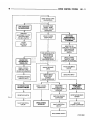
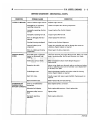
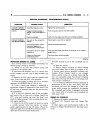
WARNING: THE USE O f THE SPEED CONTROL
IS NOT RECOMMENDED WHEN DRIVING
CONDITIONS DO NOT PERMIT MAINTAINING
A CONSTANT SPEED, SUCH AS HEAVY
TRAFFIC OR O N ROADS THAT ARE WINDING,
ICY, SNOW COVERED OR SLIPPERY.
START ENGINE
ACCELERATE VEHICLE
TO DESIRED SPEED
SPEED CONTROL
ENGAGES WHEN
ENGINE IS STARTED
PUSH ON/OFF BUTTON
TO "ON" POSITION.
FAULTY
ELECTRICAL CIRCUIT*
DEFECTIVE SERVO
SPEED CONTROL ENGAGES
WITHOUT PUSHING THE
"SET/DECEL" BUTTON
PUSH AND RELEASE
"SET/DECEL" BUTTON
FAULTY ELECTRICAL CIRCUIT*
REMOVE FOOT FROM
ACCELERATOR. SPEED
SHOULD BE CONTROLLED
j
DEFECTIVE SERVO
N O SPEED CONTROL WHEN
SET/DECEL BUTTON IS
PRESSED AND RELEASED
:
HUNTING SURGE OR
SPEED VARIATIONS
AT LOW SPEEDS
EXCESSIVE S A G
O N HILLS OR
IN TRAILER TOWING
SPEED SETTING AFTER
LOCK-IN, T O O HIGH
OR TOO LOW
FUSE BLOWN
LOCK-UP
TORQUE CONVERTER
ROUGHNESS
ENGINE
PERFORAAANCE
VACUUM LEAK
NO VACUUM AT
SERVO
AMPLIFICATION
OF ENGINE
SURGE
VACUUM
LEAK
DEFECTIVE SERVO
SPEED CONTROL
THROTTLE CABLE
DISCONNECTED
DEFECTIVE SERVO
IMPROPER STOP LAMP
AND SPEED CONTROL
SWITCH ADJUSTMENT
DEFECTIVE
CABLE
FAULTY ELECTRICAL
CIRCUIT*
DEFECTIVE SERVO
EXCESSIVE LOAD MAY
REQUIRE MANUAL
ASSISTANCE ON HILLS
DEFECTIVE
ENGINE CONTROLLER
DEFECTIVE
VACUUM PUMP
DEFECTIVE
CABLE
DEFECTIVE
VACUUM PUMP
REFER TO GROUP 5 - BRAKES
FOR VACUUM PUMP DIAGNOSIS.
*TESTS AND ADJUSTMENTS ARE DESCRIBED
IN APPROPRIATE SECTION OF SERVICE
MANUAL.
DEFECTIVE
VACUUM PUMP
J918H-27X
SPEED C01T10L SYSTEi
SH - 3
Z Z Z 3
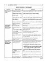
DRIVE VEHICLE OVER
ROUGH ROAD
UNIT DISENGAGES
ON ROUGH ROAD
IMPROPER
ADJUSTMENT OF STOP
LAMP AND SPEED
CONTROL SWITCH*
TAP BRAI<E PEDAL
LIGHTLY, SPEED
CONTROI. SHOULD
DISENGAGE
r
NO SYSTEM
DISENGAGEMENT
WHEN BRAKE PEDAL
IS DEPRESSED
SPEED CONTROL
DISENGAGES
FAULTY
ELECTRICAL
CIRCUIT *
EfMGSNE DOES
NOT RETURN TO
NORMAL IDLE
SPEED CONTROL
THROTTLE CABLE
KINKED OR DAMAGED
STANDARD THROTTLE
LINKAGE FAULTS
NO RESUME WHEN
BUTTON IS PRESSED
PUSH RESUME/ACCEL
SWITCH VEHICLE
SHOULD RESUME
PREVIOUSLY
MEMORIZED SPEED
VEHICLE RESUMES
SPEED
DEPRESS BRAKE
PEDAL, SPEED
CONTROL
SHOULD DISENGAGE
SPEED CONTROL
DISENGAGES
DEFECTIVE SWITCH
FAULTY ELECTRICAL
CIRCUIT'
DEFECTIVE OR
IMPROPERLY ADJUSTED
STOP LAMP AND
SPEED CONTROL
SWITCH
SPEED CONTROL
THROTTLE CABLE
KINKED OR DAMAGED
FAULTY ELECTRICAL
' CIRCUIT*
DEFECTIVE SERVO
NO SYSTEM
DISENGAGE
WHEN BRAKE PEDAL IS
DEPRESSED
DEFECTIVE ENGINE
CONTROLLER
SPEED CONTROL
SYSTEM OK
FAULTY ELECTRICAL
CIRCUIT*
RESUME SPEED
IS POSSIBLE
BELOW 20 M.P.H.
DEFECTIVE DISTANCE
SENSOR
DEFECTIVE
ENGINE CONTROLLER
J918H-28X
8H - 4
S P E E I CONTROL SYSTEM
f
T E S T
P R O C E D U R E S
INDEX
Checking for Fault Code
Distance (Speed) Sensor Test
Inoperative System
Road Test
Speed Control Cable Attachment—Engine
page
4
. 4
4
4
7
ROAD TEST
Road test vehicle to verify reports of speed control
system malfunction. The road test should include attention to the speedometer. Speedometer operation
should be smooth and without flutter at all speeds.
Flutter in the speedometer indicates a problem
which might cause surging in the speed control system. The cause of any speedometer deficiencies
should be corrected before proceeding.
INOPERATIVE SYSTEM
If road test verifies that system is inoperative and
speedometer operation is satisfactory, inspect for
loose electrical and vacuum connections at the servo.
Corrosion should be removed from electrical terminals and a light coating of Mopar Multi-Purpose
Grease, or equivalent, applied.
Inspection should also be made to verify that both
ends of the speed control cable are securely attached.
CHECKING FOR FAULT CODE
(1) When trying to verify a speed control system
electronic malfunction use a DRB II to determine the
cause (refer to Powertrain Diagnostic Procedures
manual).
(2) Correct any problems found and recheck for
Fault Code if changes were made.
DISTANCE (SPEED) SENSOR TEST
For testing of the distance sensor and related components refer to the Powertrain Diagnostic Procedures manual.
SPEED CONTROL SYSTEM ELECTRICAL TESTS
Electronic speed control systems may be tested using two different methods. One involves use of a
DRBII. If this test method is desired, please refer to
the Powertrain Diagnostic Test Procedures manual.
The other test method uses a voltmeter. The voltmeter method is described in the following tests.
If any information is needed concerning wiring, refer to Group 8W - Wiring Diagrams. .
CAUTION: When test probing for voltage or continuity at electrical connectors, care must be taken
not to damage connector, terminals, or seals. If
page
Speed Control Cable Attachment—Servo
Speed Control Switch Test
Speed Control System Electrical Tests
Stop Lamp Speed Control Switch Test
Vacuum Supply Test
7
5
4
5
6
these components are damaged, intermittent or
complete system failure may occur.
ELECTRICAL
TESTS
AT
SERVO
(1) Turn ignition switch to the ON position. With
the speed control switch in the ON position, set up a
voltmeter to read battery voltage and connect the
negative lead to a good chassis ground.
(2) Disconnect the 4-way connector going to the
servo (Fig. 2). The blue wire with the red tracer of
the main harness 4-way connector should read approximately battery voltage. If not, check for loose
connections, brake switch adjustment or, repair the
main harness as necessary.
(3) Connect a jumper wire between the male and
female terminals of the blue wire with red tracer.
The other three male terminals from the servo
should show battery voltage. If not, replace the servo.
(4) Using an ohmmeter, connect one lead to a good
body ground. Touch other lead to the black (BK) wire
terminal in the 4-way connector of the main harness.
The meter should show continuity. If not, repair the
ground circuit as necessary.
ELECTRICAL
CONTROLLER
TESTS
AT
ENGINE
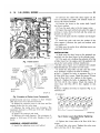
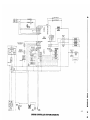
(1) Unplug 60-way connector from the engine controller, located on the left fender (Fig. 3).
(2) Connect negative lead of voltmeter to a good
body ground near the module.
(3) For the following tests, the ignition switch must
be in the ON position. Refer to Fig. 4 for controller
terminal locations. Touch the positive lead of the
voltmeter to the terminal in cavity number 33. With
the speed control switch in the OFF position, the
voltmeter should read 0 volts. With the speed control
switch in the ON position, the voltmeter should read
battery voltage. If not, repair the main harness as
necessary.
(4) Touch the positive lead of the voltmeter to the
terminal in cavity number 53. As in step (3), the
voltmeter should read 0 volts with the switch in the
OFF position and battery voltage with the switch in
the ON position.
SPEED CONTROL SYSTEM
•
8H - 5
A VACUUM
y- HOSE
OOOOOOOOOO
11
20
0 ooooooooo
1
10,
oooooooooo
x
oooooooooo^
uO
, )OOOOOOOOO
31
A
/
C1
\L IE
2
Fig. 4 Engine
J918H-25
Fig.
2 Servo
And Harness
Connector
SINGLE BOARD
ENGINE CONTROLLER
SPEED CONTROL
SERVO
Fig. 3 Engine
Controller
J918H-29
and Connector
Location
(5) Touch the positive lead of the voltmeter to the
terminal in cavity number 48. With the speed control
switch in the OFF position, the voltmeter should
read 0 volts. With the switch in the ON position, the
voltmeter should read battery voltage. Pressing the
SET button should cause the voltmeter to change
from battery voltage to 0 volts for as long as the
switch is held. I f not, perform the speed control
switch test. If the switch is not at fault, then check
the main harness and repair as necessary.
3
utar
°50|
Controller
from
umr
60-Way
Terminal
RR8HC7
Connector
End
Shown
(6) Touch the positive lead of the voltmeter to the
terminal in cavity number 50. The voltmeter should
read 0 volts with the speed control switch in either
the OFF or ON position. With switch in either RESUME or SET position, the voltmeter should read
battery voltage. I f not, perform the speed control
switch test. If the switch is not at fault, then check
the main harness and repair as necessary.
(7) Touch the positive lead of the voltmeter to the
terminal in cavity number 49. The voltmeter should
read 0 volts with the switch in the OFF position.
With the switch in the ON position, the voltmeter
should read battery voltage. The voltmeter will continue to read battery voltage when either the SET or
RESUME switch is pressed. If not, perform the speed
control switch test. If the switch is not at fault, then
check the main harness and repair as necessary .
(8) Using an ohmmeter, connect one lead to a good
body ground and touch the other lead to the terminal
in cavity number 29. With the brake pedal released,
the meter should show continuity. When the pedal is
depressed, the meter should show open circuit.
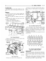
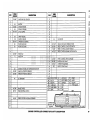
SPEED CONTROL SWITCH TEST
To check the switch, remove the switch from its
mounting position. Use an ohmmeter and refer to the
Switch Continuity Chart to determine i f continuity is
correct. If there is no continuity at any one of the
switch positions, replace the switch.
STOP LAMP SPEED CONTROL SWITCH TEST
(1) Disconnect the connector at the stop lamp
switch. Using an ohmmeter, continuity may be
checked at the switch side of the connector as follows
(Fig. 5):
(a) With the brake pedal released, there should
be no resistance between:
• the black (BK) and white with red tracer (WT/PK)
wires
• the yellow with red tracer (YL/RD)
• dark blue with red tracer (DB/RD) wires
• pink (PK) and white (WT) wires.
8H - 6
SPEED
SPEED CONTROL SYSTEM —
CONTROL
SWITCH
— —
—
—
4
CONTINUITY
CHART
CONNECTOR TERMINAL END
18WT
18PK
SWITCH
SPEED CONTROL SWITCH
CONTINUITY
SWITCH POSITION
CONTINUITY BETWEEN
OFF
PIN 1 AND PIN 4
ON
PIN 1 AND PIN 4
PIN 1 AND PIN 2
PIN 2 AND PIN 4
ON AND SET
PIN 1 AND PIN 2
ON AND RESUME
PIN 1 AND PIN 3
STOP LAMP AND SPEED
CONTROL SWITCH WITH
SPEED CONTROL
Fig. 5 Stop
Lamp
Switch
Connector
918H-14
(b) With brake pedal depressed, there should be
continuity between pink (PK) and white (WT)
wires. There should be no continuity between black
(BK) and white with' red tracer (WT/PK) wires.
There should be no continuity between the yellow
with red tracer (YL/RD) and dark blue with red
tracer (DB/RD) wires.
(2) I f the above results are not obtained, the stop
lamp switch is defective or out of adjustment.
Stop lamp switch adjustment is detailed in Group 5
- Brakes.
VACUUM SUPPLY TEST
(1) Disconnect vacuum hose at the servo and install
a vacuum gauge in the hose (Fig. 6).
(2) Start engine and observe gauge at idle. Vacuum
gauge should read at least ten inches of mercury.
(3) I f vacuum does not meet this requirement,
check for vacuum leaks or poor engine performance.
Fig. 6 Vacuum
Gauge
Test
J908H-8
SPEED C0IT10L SYSTEi
8H - 7
SPEED CONTROL CABLE ATTACHMENT—ENGINE
(1) The clevis of the speed control cable is retained
to the bellcrank by a washer and hairpin clip.
(2) Visual inspection will verify that the cable is
securely attached. If the cable is not attached, the
speed control system will be inoperative.
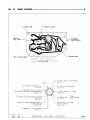
SPEED CONTROL CABLE ATTACHMENT-SERVO
The speed control cable is attached to the servo
with a wire clip (Fig. 7). A check should be made to
verify- that the clip is in place. If the clip is missing
the speed control system will be inoperative.
Fig.
7 Speed
Control
Cable
Attachment
at
Servo
8H - 8
•
SPEEI CONTROL SYSTEi
SERVICE PROCEDURES
SERVO UNIT
REMOVAL
, (1) Disconnect vacuum hose at servo.
(2) Disconnect electrical connector at servo.
(3) Remove 2 nuts from servo mounting bracket.
(4) Pull servo away from mounting bracket.
(5) Remove and discard push nuts on servo studs.
(6) Pull speed control cable away from servo to expose cable retaining clip.
(7) Remove clip attaching cable to servo.
INSTALLATION
(1) With bellcrank pivoted full rearward align hole
in cable sleeve with hole in servo pin and install retaining clip.
(2) Insert servo studs through holes in the cable.
(3) Install new push nuts on the servo studs.
(4) Insert servo studs through holes in servo
mounting bracket. One stud mounts reservoir,
(5) Install the 2 attaching nuts and tighten to 6
N*m (50 in. lbs.).
(6) Connect vacuum hose to servo.
(7) Connect the electrical connector to servo terminals.
(7) Install cable end on bellcrank rod.
(8) Install washer and hairpin clip on end of bellcrank rod.
SPEED CONTROL SWITCH
REMOVAL
(1) Disconnect battery negative cable.
(2) Remove 2 screws from back side of steering
wheel (Fig. 1).
(3) Rock switch away from horn pad while lifting
switch out of steering wheel.
(4) Disconnect 4-way electrical connector from
clockspring.
COVER
STEERING
HORN
SERVO THROTTLE CABLE ASSEMBLY
REMOVAL
(1) Remove hairpin clip and washer retaining cables on bellcrank. Remove servo throttle cable from
bellcrank.
(2) Disconnect cable at servo and remove cable assembly.
INSTALLATION
(1) Locate cable through servo mounting bracket.
(2) Connect cable sleeve to servo stud, align holes,
and install hairpin clip.
(3) Insert servo studs through holes in cable.
(4) Install new push nuts on servo studs.
(5) Insert servo studs through holes in bracket. Install nut washers and torque to 6 N*m (50 in. lbs.).
(6) Route cable from servo, to cable support
bracket.
WIRE
HARNESS
Fig.
1 Speed
Control
RETAINING
SCREW
Switch
J9119-8
Removal
INSTALLATION
(1) Connect 4-way electrical connector from clockspring to switch.
(2) Place switch in steering wheel, sliding the forward edge of switch under horn pad. Line up locating
pins on switch with holes in steering wheel frame.
(3) Attach switch to wheel with 2 screws starting
with the screw at the left end of the switch.
VACUUM PUMP
Refer to Group 5 - Brakes for removal and installation of the vacuum pump.
WIRING DIAGRAMS
•
8W - 1
WIRING DIAGRAMS
INDEl
Name
Wiring Diagram
Sheet Number
A/C and Heater System
Blower Motor
.27
Blower Motor Resistor
27
Clutch Cycling Switch . . . . . . . . . . . . . . . . . .
. .28
Compressor
28
Fuse -. . .
27
Heater Blower Switch
27
Low Pressure Switch
.28
Vacuum Switch
.27
Zener Diode
.28
Anti-Lock Brake System
.13, 14
Brake Warning Switch
14
Controller
13
Diagnostic Connector
.13
Dual Solenoid Hydraulic Valve
.14
Electric Vacuum Sensor
14
Fuse
13
Ground
.14
Park Brake Switch
13
Resistor
14
R.W.A.L. Sensor
.14
Stop Lamp Switch
14
Bulkhead Connector
33, 34
Charging System
1,2
Alternator
.2
Battery
1
Fusible Links . . . . . . . . . . . . . . . . . . . . . . . . . . . . . .2
I.O.D. Connector
1
Voltage Regulator
2
Engine Controller Connector .
35
Engine Wiring
.7, 8, 9, 10, 11
Air Heater
7
Air Heater Relay
7
Battery
• .7
Diagnostic Connector
10
Distance Sensor
. • .9
Engine Controller
8, 9, 10
Fuel Heater
.11
Fuel Pump
11
Fusible Link
7
Ground
11
K.S.B. Motor
.11
Resistor
11
Thermo Switch
.11
Throttle Position Transducer
10
Temperature Sensor
8
Water-in-Fuel Sensor
8
Four Wheel Drive Indicator System
Fuse
31
Lamp
.31
Transfer Case Switch
.
31
Front End Lighting
Left Headlamp
.17
Name
Wiring Diagram
Sheet Number
Left Headlamp Ground
.'
Left Park and Turn Signal Lamp
Left Side Marker Lamp
Right Headlamp
Right Headlamp Ground
Right Park and Turn Signal Lamp
Right Side Marker Lamp
Front End Lighting (Canada)
Daytime Running Light Module
Left Headlamp
•
Left Headlamp Ground
Left Park and Turn Signal Lamp
Left Side Marker Lamp
Right Headlamp .
Right Park and Turn Signal Lamp
Right Side Marker Lamp
•
Fuel Tank System
Fuse
Sending Unit .
Headlamp High Beam Switch
Headlamp Switch . .
Headlamp Switch Controlled Interior Lighting
A/C Heater Switch Lamp
Ash Receiver Lamp
Ground
Headlamp Switch Ground
Ignition Switch
Message Center
»
Message Center Splice
Oil Pressure and Temperature Warning System
Coolant Temperature Sending Unit
Oil Pressure Sending Unit Switch
Overdrive Lockout System A518
Coolant Thermal Switch
Control Module
Engine Controller
Lockout Solenoid
Lockout Switch
Transmission Thermal Switch
Rear Lighting System
Seat Belt Warning System
Combined Buzzer
Fuse
Seat Belt Switch
Speed Control System
Clockspring
Engine Controller
Fuse
••
Resistor
Servo
Speed Control Switch
,
Stop Lamp Switch
Starter System
17
.17
17
18
18
18
18
20
19
.19
y.19 t p ^
19
£
-20
20
20
32
32
• .21
. .21
22
22
22
• .22
22
, -5
25
26
12
12
12
6
.6
6
.6
6
. .6
6
29, 30
.32
32
32
•
16
15
16
16
15
.16
16
3, 4
8W - 2
WIRING DIAGRAMS
Name
Back-Up Lamp Switch
Clutch Switch . . .
Neutral Start Switch
Relay
Starter Motor
Stop/Turn and Hazard Flasher System
Fuse . . . . . . . . . . .
Hazard Warning Flasher
Switch . .
Turn Signal Flasher
•
Wiring Diagram
Sheet Number
.3
4
3
3
3
.24
24
24
24
Name
\
Windshield Wiper System
Fuse
Ground
Motor
Switch
Washer Motor
^
Wiring Diagram
Sheet Number
23
23
23
23
23
8W - 4
WIRING DIAGRAMS
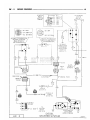
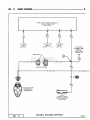
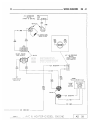
TO IGNITION f
SWITCH
r
(SEE SH 5)
• J2 14DB
TO LEFT
ENGINE WIRING Y(SEE SH 11)
DJ2 14DB
•J2 14DB
TO <J2> 2 I SPLICE
TO DIAGNOSTIC
CONNECTOR
(SEE SH 10)
J2 14DB-
• J2 14DB
(SEE SH 7)
J2 14DB-
(REAR OF BATTERY)
BODY
GROUND
(LEFT YOKE
FRONT OF
BATTERY)
ENGINE
GROUND
(LEFT FRONT
OF ENGINE)
I.O.D.
CONNECTOR
NATURAL
(FRONT LEFT
SIDE SHIELD)
Al 2/0 RD-
TO HAZARD f
FLASHER
Y
(SEE SH 48)
Al
2/0 RD
AD 1
«
A3 16PK
A3 16PK
A3 22WT
S5 14BR
S5 14BR
TO STARTER
MOTOR
(SEE SH 3)
#23 [ n j
-BLACK
(REAR OF BATTERY)
TO STARTER
RELAY
(SEE SH 3)
FUSIBLE LINK
(HYPALON WIRE)
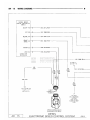
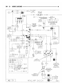
CHARGING SYSTEM WITH DIESEL
5.9L ENGINE
J918W-13
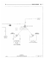
WIRING DIAGRAMS
8W - 5
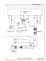
R9 6BK*
GROUND
(ON ENGINE)
(SEE SH 21)
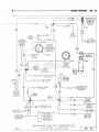
J918W-13
CHARGING SYSTEM WITH DIESEL
5.9L ENGINE
AD
2
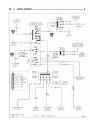
WIRING DIAGRAMS
8W - i
#
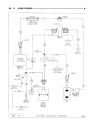
STARTER
RELAY
(LEFTSIDE
SHIELD)
TO CHARGING
SYSTEM
(SEE SH 1)
S2 16YL
S4 18BR/YL*
54 18BR/YL*
55 14BR
S5 18BR
A1 12RD
Bl 18WT
S4 18BR/YL*
B2 1SVT/BKX
AUTOMATIC TRANSMISSION / '
NEUTRALSTARTAND
/
BACK-UPSWITCH
/
(ON TRANSMISSION)/
S4
20BR
YL *
\ MANUAL TRANSMISSION
\BACK-UPLAMPSWITCH
\ (ON TRANSMISSION)
TO SINGLE
BOARD ENGINE
CONTROLLER
(AUTO/TRANS)
CAVITY 30
(SEE SH 11)
S4
18BR
YL*
B1
18WT
!
B2
18VT
BK*
— BLACK
(REAR
OF
ENGINE)
DARK GRAY
DARK GRAY
MANUAL TRANS
(REAR OF
ENGINE)
T0<flj72lGRPJA
#25
SPLICE
(SEE SH 11)
N
<f B2 18VT/BKX-Y
TO BACK-UP
LAMPS
(SEE SH 29)
FUSE #13
(20 AMP)
TO
>—J2 - 14DB —
J IGNITION
}
SWITCH
(SEE SH 5)
DIESEL
AD
3
STARTER SYSTEM
STARTER MOTOR
(LEFT LOWER
REAR OF ENGINE)
J918W-13
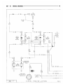
WIRING DIAGRAMS
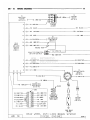
•S2 14YL •
8W - 7
TO IGNITION
SWITCH
(SEE SH 5)
S2
14YL
S2
16YL—
S21
14YL*-
* 0
3
(NEAR CLUTCH
ROD)
BLACK-
S5
18BR
MANUAL
TRANSMISSION
\
TO ENGINE
CONTROLLER
(CAVITY 8)
(SEE SH 8)
BLACK-
BLACK
18BK
AUTOMATIC
TRANSMISSION
18BK
S2 14YL
CLUTCH SWITCH
(ON CLUTCH ROD)
BYPASS JUMPER
(TAPED TO WIRE HARNESS)
SWITCH CLOSES WHEN
CLUTCH I S DEPRESSED
DIESEL
J918W-13
STARTER SYSTEM
AD
4
8W
•
WIRING DIAGRAMS
8
TO BACK-UP
LAMP SWITCH
(SEE SH 3)
FUSE # 1 3
(20 AMP)
TO CHARGING
SYSTEM
(SEE SH 2)
T
T
Bl 18WT
IGNITION SWITCH
(ON STEERING COLUMN)
G5 20DB*—^
T 0
(SEE SH 50)
Jl
12RD
» - J 2 14DB
#49
TO <J2
SPLICE
(SEE SH 1)
- J l 12RD
TO
STARTER C
SYSTEM >
(SEE SH 4)'
<G5> SPLICE
TO
AIR CONDITIONING
ANDHEATERFEED
(SEESH 58,59,61)
-S2 14YL
FUSE* 1
(30 AMP)
• J10 12PKX
IjeiJ
Q20
GROUND
(THRU STEERING
COLUMN
ATTACHMENT)
Q2
14BK*
J10
#50 12PK*
-CI
12BK/RDXFUSE # 2
(30 AMP
CIRCUIT
BREAKER)
i
TO
POWER
>-Wl 12TN/BKX—{ WINDOWS
(SEE SH 63)
P51
TO CHARGING
SYSTEM
(SEE SH 2)
12BR —
20BK/GYX-
P51
20BK/GYX-
FUSE #9
(20 AMP)
S2
-J2
P51
P51
J10
Q20
Q2
J1
14YL
14DB
20BK/GY*
20BK/GYX
12PK*
12BK/RD*
V6 18DB—^
14BK*
V6 18DB~5
12RD
TO CIGAR LIGHTER
(SEE SH 44)
AD 5
TO
BRAKE WARNING
LAMP SWITCH
(SEE SH 13)
FUSE #10
(20 AMP)
Dl
TORADIO
(SEESH
53, 55, 57)
14RD/YL*-
TO TURN SIGNAL
SYSTEM
(SEE SH 48)
IGNITION
TO WIPER
SYSTEMS
(SEE SH 23)
SWITCH
TO R.W.A.L.
MODULE
(SEE SH 13)
P51
20BK
GYX
TO
L i MESSAGE
' CENTER
(SEE SH 25)
J918W-13
WIRING DIAGRAMS
-J2 14DB
8W - S
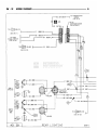
G5 20DB>
BLACKU4 20OR/WTX
G5
20DBX
TO IGNITION
SWITCH
(SEE SH 5)
U5 20YL/BK*
(SEE SH 25) <G5
G5 20DBXU50 20YL/DB t
H4 20BK-
E10 200R/YLX
I
I
U50 20YL/DB *
G5 20DBX
I
I
U5 20YL/BK t
NATURAL \
I
I
E1 0 20OR/YLX
SINGLE
BOARD
ENGINE
CONTROLLER
(SBEC)
CONNECTOR
(SEE SH 34)
OVERDRIVE MODULE
(RIGHT SIDE ON
SUPPORT BRACKET)
T
H4
U4
20OR
WT*
20BK
-H4 20BK-
1
T0<H4>1 J SPLICE
(SEE SH 22)
•U6 20 RD/WT
U4Q 20OR/LGXU6 20RD/WT* =
U4 20OR/WT*
U5 20OR/BK
lilij
COOLANT THERMAL
SWITCH
TRANSMISSION
THERMAL SWITCH
OPENS
BELOW
60°F
OPENS
ABOVE
278°F
DARK GRAY
(REAR OF
ENGINE)
= U40 20OR/LG-*
( LEFT REAR
Of ENGINE)
TO<J2^jJ
SPLICE } -
-J2 14DB-
(SEE SH 11)
J918W-13
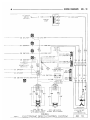
OVERDRIVE LOCKOUT SYSTEM (DIESEL)
(A518 AUTO/TRANSMISSION)
OVERDRIVE LOCKOUT
SOLENOID
(ON TRANSMISSION)
AD
6
8W - 10
WIRING DIAGRAMS
O)
-A5 12BK
TO
BATTERY
POSITIVE
A5
6BK
-A5 6BK-
A4 6BK
(LEFT
FENDER
SIDE
SHIELD)
TO
(SEE SH 1)
(LEFT
FENDER
SIDE
SHIELD)
SPLICE
A6 6BK-
A6
6BK
-S21 18YL/BKX-
AIR
INTAKE
HEATER
(ON INTAKE
UNDER INLET
PIPE)
E5
20 DG
WT*
L
#11
TO MESSAGE
CENTER (DIESEL)
(SEE SH 25)
E5
20DG
WT*
S21
-J2 14DB-S22
TO STARTER ,
RELAY
y
(SEE SH 7)
18YL/BK % -
180R/BKX-
— S5 18BR
-E5 20DG/WTX-
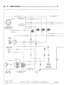
AD 7
DIESEL ENGINE WIRING
J918W-13
•
WIRING DIAGRAMS
8W - 11
TO GROUND EYELET
(SEE SH 11)
•N5 18BK/LB•
K5
1 6BK X
•K32 20TN/BKX-
DARK GRAY
(REAR OF ENGINE ) N
TL=5L
9
9 ° ° O
J
J
S20 18LBXDARK GRAY
TO
DISTANCE
SENSOR
(SEESH 12)
20TN
TO VACUUM
SENSOR
(SEE SH 14)
18BK
r
K32
20TN
BKX
#AAA#
WATER-1N-FUEL SENSOR
(IN FUEL F I L T E R )
S20
18LB
BKX
K5
18BK*
K5
18BK* \
TEMPERATURE
SENSOR
K31 20BK/PKX
-K31 20BK/PK XK32
20TN
BKX
#38
TO MESSAGE /Q)
CENTER
r
(DIESEL)
W
(SEE SH 25)
W
L
TO DIAGNOSTIC CONNECTOR
(SEE SH 10)
C.
DK5 16BK*
J
1 - » - K32 20TN/BKX$21 18YL/BKX•
-J2 14DB- 522 180R/BKX— S5 18BR
-E5 20DG/WTX•
J918W-13
16
ENGINE
CONTROLLER
9
5 4 - » K31 20BK/PKX-
5 h »
-K5 18BKX
15
8
56
FOR
CONNECTOR
(SEE SH 35)
21 - » - S 2 0
18LB/BKX
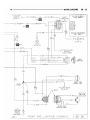
DIESEL ENGINE WIRING
AD 8
8W - 12
WIRING DIAGRAMS
SINGLE BOARD ENGINE CONTROLLER
(DIESEL) CONNECTOR
(SEE SH 35)
29
T
T
T
S4
20BR
YL*
D40
18WT
PK*
J11
16RD
47
30
G7
20WT
OR*
UK
TO STOP LAMP
SWITCH
(SEE SH 14, 16)
TO FUSIBLE
LINK
(SEE SH 2)
TO STARTER
RELAY
(SEE SH 3)
TO DAYTIME
RUNNING LAMP
MODULE
(CANADA ONLY)
(SEE SH 20)
<8>-
DARK GRAY
T
G7
20WT
OR*
I
G7 20WT/OR*-
-G7 20WT/OR*
(REAR OF ENGINE)
^1
G7
20WT
OR*
-N5 20BK/LB*
m
-N5 20BK/LB *-
m
go]
G7
20WT
OR*
DISTANCE SENSOR
(ON REAR OF
TRANSMISSION)
TO LEFT
PRINTED CIRCUIT
BOARD CONNECTOR
(SEE SH 52)
AD 9
DIESEL ENGINE WIRING
J918W-13
WIRING DIAGRAMS 8W 13
SINGLE BOARD ENGINE CONTROLLER
CONNECTOR
(SEE SH 35)
11
12
25
45
4
6
22
23
BLACK
(REAR OF ENGINE)
THROTTLE POSITION
TRANSDUCER
(AUTO/TRANS ONLY)
J918W-13
DIESEL ENGINE WIRING
AD 10
8W - 14
WIRING DIAGRAMS
RESISTOR
THERMO
SWITCH
J2
-14DB-
TAPED IN
HARNESS NEAR
THERMO SWITCH
BLACK •
J2
14DB
J2
14DB
RD*
-BLACK
SPLICE
(SEE SH 1)
COLD START
ADVANCE
(K.S.B. MOTOR)
(FRONT OF
ENGINE)
TO OVERDRIVE
LOCKOUT SOLENOID
(SEE SH 6)
(AUTO/TRANS)
J9 14BK
BLACK
\
\
S4
18BR
YL*
4 x 4 ONLY I
X9
18BK
i
| TO TRANS/CASE f
SWITCH
r (SEE SH 31)
-K5 16BKX
J9
14BK
1
1
TO STARTER
RELAY
(SEE SH 3)
(REAR OF
ENGINE)
-JTO <^>T1
J2
14DB
MANUAL
TRANSMISSION
1
SPLICE
FUEL PUMP
(CENTER OF
ENGINE)
FUEL
HEATER
(REAR OF
ENGINE)
(SEE SH 8)
AD 11
DIESEL ENGINE WIRING
J918W-13
WIRING DIAGRAMS
8W - 15
TO LEFT
PRINTED CIRCUIT
BOARD CONNECTOR
(SEE SH 56)
*17[jO
/ O O u u O
G20 20VT/YLX
« —
-G20 20VT/YLX-
GRAY
-G6 20GY-
G6 20GY
BLACK
19
G60 20GY/YLX
00
« —
•G60 20GY/YL*
TO RIGHT
PRINTED CIRCUIT
BOARD.CONNECTOR
(SEE SH 56)
BLACK
(REAR OF ENGINE
G20
20VT
YL*
G60
2QGY
YL*
G60 20GY/YLX-
G6
20GY
G6 20GY-
G20
20VT
YL*
OIL PRESSURE
SENDING UNIT
AND SWITCH
(LEFT SIDE
OF BLOCK
CENTER)
TEMPERATURE
SENDING UNIT
(LEFTREAR
OF CYLINDER
HEAD)
G60 20GY/YLXG6 20GY -
J918W-13
OIL PRESSURE AND TEMPERATURE
SYSTEM FOR DIESEL ENGINE
AD 12
8W - 16
WIRING DIAGRAMS
TO
TURN SIGNAL
FLASHER
(SEE SH 48)
REAR
WHEEL
ANTI-LOCK
CONTROL
MODULE
(R.W.A.L.)
)—02
f
•Dl 18RD/YLX
h
3
-01
14RD/YLX
I
-IS1 1 6 L G X -
8
•DS1 14WT/BRX-
II
-VS1
4
-X4
14
-B01
18RD/VTX-
13
-B02
18WT/VTX-
18LB
14BK*-
TO
< IGNITION
> SWITCH
(SEE SH 5)
FUSE#9
(20 AMP)
-IS1 16LGX-DS1 14WT/BRX-
—
VS1 18LB
TO
4WD INDICATOR
r
~i LAMP SWITCH
(SEE SH 31)
20LG/BR X ~
TWISTED PAIR
B01 18RD/VT X •
ROLLS TEST CONNECTOR
(IN-PLANT USE ONLY)
B02
18WT/VTX
•04 18WT/TNX-
D4 18WT/TNX-
•03 20PK/DBX-
D3 20PK/DBX-
•P2 20BK/GYX10
12
-»
ATI 1 SOR.-
1
TO
MESSAGE CENTER
(DIESEL)
(SEE SH 25)
PS 20GY/BK X •
P2 20BK/GYX-
DK 18BKX
H40
18BK/LG X-
TO
INTERMITTENT
WIPER MODULE
(SEE SH 46)
BLACK
-GRAY
D4 18WT/TNXP2 20BK/GYXP5 20GY/BKXX4 20LG/BRXDl
14RD/YLXAT1 180R IS1 16LGX-
<d
E
-101
18RD/VTX
-B02
18WT/VTX
-DK 18BKX
-VS1
18LB
SERVICE
DIAGNOSTIC
CONNECTOR
(LOWER RIGHT
SIDE COWL)
TO
IGNITION
SWITCH
(SEE SH 5)
H40 18BK/LGX
-03 20PK/DBX
-DS1 14WT/BRX
PARK BRAKE
SWITCH
AD
13
REAR WHEEL ANT I-LOCK BRAKE SYSTEM
(DIESEL ENGINE)
J918W-13
WIRING DIAGRAMS
B09 18GY/WTX-
(LEFTREAR
FRAME RAIL)
-cnQ)—|
PANEL GROUND
8W - 17
^
BLACK-
i— B09 18GY/BK*
RESET SWITCH
#OTP
ISO SOL
DUAL SOLENOID
HYDRAULIC VALVE
BRAKE WARNING
LAMP SWITCH
(LEFT FRONT I
FRAME RAIL) -ft
31
(LEFT SIDE UNDER INSTRUMENT PANEL)
-BOl
B01 18RD/VT*
18RD/VTX•
•B02 18WT/VTX-
B02 18WT/VT*
TWISTED PAIR
it
-04 18WT/TN*-
TO
HAZARD
? FLASHER
SWITCH
(SEE SH 24)
x
04 16WT
-03 20PK/DBXD4
18WT
TN*
03
20PK
DB*
TO
BUZZER
SEE SH 32)
BOl B02
18RD 18RD
VT* VT*
(TAPED IN
HARNESS NEAR
CONNECTOR)
TWISTED
PAIR
•04 20WT/TNX-
03 18PK/DB*H4 18BK
•
H4 20BK
L
-D40 18WT/PKX-
BLACK
RESISTOR
BOl
20PK
#41
18WT
18PK
TO
DIAGNOSTIC
CONNECTOR
(SEE SH 10)
SIDE SHIELD)
J918W-13
R
E
A
R
D40
18WT/PK*
X
TO ENGINE
CONTROLLER
(SEE SH 9)
o
STOP LAMP SWITCH
(LEFT FENDER
802
20LG
OR*
R.W.A.L. SENSOR
IN REAR DIFFERENTIAL)
^ E E L ANT I -LOCK BRAKE SYSTEM
(DIESEL ENGINE)
AD 14
8W
18
•
WIRING DIAGRAMS
S I N G L E BOARD
ENGINE CONTROLLER
(SBEC)
ON/OFF 49
X32 20YL/RDX-
-
»
—
SET 48 ^
>
—
•X31 20BR/RD*
RESUME 5 0 -
»
—
•X33 20WT/LG* -
BRAKE QQ
SENSE ^
»
—
•D40 18WT/PK*-
VACUUM 3 3 -
»
—
•X36 20TN/RD* -
VENT 53 CONNECTOR
(SEE SH 35)
»
—
-X35 20LG/RD* -
-
X30 20DB/RD * TO R.W.A.L.
(SEE SH 14)
X9B
20BK
X30
20DB
RD*
X36
20TN
RD*
D40
18WT
D3
20PK/DB* •
X35
20LG
RD*
X9B 20BK
D3
18PK
DB*
TO\C9> SPLICE
(SEE SH 23)
DIRECT
k
CONNECTION- 1
TO SERVO
TO SEAT
BELT WARNING
SYSTEM
(SEE SH 22)
FUSED BATTERY
FEED
SPEEDCONTROLSERVO
(UNDER BATTERYTRAY)
AD 15
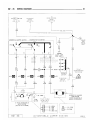
DIESEL
ELECTRONIC SPEED CONTROL SYSTEM
J918W-13
WIRING DIAGRAMS
•
TO IGNITION ,
switch
y
(SEE SH 5)
J2
14DB
X34
8W - 11
20RD/LB f'
FUSE #11
2 AMP
#10
-X32 20YL/RD*-
-X32 20YL/RDX#8
M
•X31
20BR/RDX-
—»-
-X31
20BR/RD*TO R.W.A.L.
MODULE
(SEE SH 14)
X32
20YL
RDX
#9
E)
X33 20WT/LGXJ
-X33 20WT/LGX- — » -
D4 18WT/TNXM ^
-X30
20YL/RD* - - f l
20BR/RD*
X34
X33
20RD/LB*
20WT/LG*
7
20DB/RDX- — » —
•D4 16WT-
TO < H 4 T | 5—
GROUND SPLICE
(SEE SH 22)
D3
X32
X31
X30
20DB
RDX
H 4
20BK
TO HAZARD
FLASHER SWITCH
(SEE SH 48)
20PK/DBX
D3 18PK/DB X
•D4 20WT/TN XRESISTOR
D40 1 8 W T / P K X - » - D 4 0 18WT/PKX
H4 20B"
mil
#41
•
18WT
PKX
18WT
18BK
18PK
18DB
RDX
18YL
RDX
(TAPED IN
^HARNESS NEAR
nCONNECTOR)
18WT
PKX
18BK
18WT
18PK
o
o
STOP LAMP AND
SPEED CONTROL SWITCH
WITH SPEED CONTROL
J918W-13
O
STOP LAMP SWITCH
WITHOUT SPEED CONTROL
DIESEL
ELECTRONIC SPEED CONTROL SYSTEM
SPEEDCONTROL
SWITCH
(IN STEERING WHEEL)
AD
16
8W - 21
•
WIRING DIAGRAMS
LEFT SIDE
MARKER LAMP
LEFT PARK
AND TURN
SIGNAL LAMP
AD 17
(LEFT REAR RADIATOR
YOKE PANEL)
FRONT END LIGHTING
J918W-13
WIRING DIAGRAMS
TO <C9> SPLICE
C9 14BK-
(SEE SH 23)
C9 14BK-
05
18TN
8W - 21
05
18TN
1*22
RIGHTHEADLAMP
GROUND
(CENTER DASH
PANEL)
L3 14RD/0R*—i
L9 20BK-
AO
L4 16VT*-
RIGHT
HEADLAMP
L3 14RD/OR*L7
18BK.
YL*
TO BLOWER MOTOR
(SEE SH 27)
C9 14BK-
L7 18BK/YL*•
-05 18TN
C9 14BK
RIGHT SIDE
MARKER LAMP
L7
183K
YL*
D5 18TN
L9 18BK
H)
in
•18BK/YL*-
RIGHT PARK
ANO TURN
SIGNAL LAMP
18BK-
18TN(RIGHT REAR
RADIATOR YOKE)
J918W-13
FRONT END LIGHTING
AD 18
8W - 22
WIRING DIAGRAMS
L33 16RD/BK*-
L33 16RD/BKX
TO DIMMER SWITCH
(SEE SH 39)
BLACK
TO TURN
SIGNAL SYSTEM
(SEE SH 24
TO RIGHT
PRINTED CIRCUIT
BOARDCONNECTOR
(SEE SH 52)
^
y\
TO <L7>7] SPLICE 5
& 26
L7 18BK/YLX
(SEE SH 21)
LEFT
HEADLAMP
LEFT PARK
AND TURN
SIGNAL LAMP
AD 19
(LEFT REAR RADIATOR
YOKE PANEL)
FRONT END LIGHTING
(CANADA)
J918W-13
WIRING DIAGRAMS
TO H E A D L A M P _
SWITCH
y
( S E E SH 21)
•L20
18LG/BK %-
L20
14LG/BKX-
L33 16RD/BKX# 12
-<f
I
L33 16RD/BKX-
Mi
DAYTIME RUNNING
LIGHT MODULE
(DIRECT
CONNECTION
TO
MODULE)
C
G7
20WT
I — J 9 16BK-
(ENGINE COMPARTMENT
LEFT SIDE)
J2
14DB
05
18TN
L4
16VT*
TO
05
18TN
T0<^>SPLICE
<3>
a|#22
(SEE SH 9)
SPLICE
(SEE SH 10)
L3
14RD
OR*
L4 16VTXL3
8W - 23
TO
A
14RD/0RX-
>
ENGINE
WIRING
(SEE SH 2)
(DIESEL ENGINE)
L9 22BK
-L4 16VTX
L4 16VTXL3
—no
RIGHT
HEADLAMP
14RD/0R*-
L7 18BK/YL % -D5
C9
18TN
14BK-
RIGHT SIDE
MARKER LAMP
TO BLOWER MOTOR
(SEE SH 26)
RIGHT PARK
AND TURN
18 BK/YL*-, SIGNAL LAMP
(RIGHT REAR
RADIATOR YOKE)
RIGHT
HEADLAMP
GROUND
(Q
(CENTER
DASH PANEL)
J918W-13
FRONT END
LIGHTING (CANADA)
AD
20
8W - 24
WIRING DIAGRAMS
Ll
12RD*
-LI
12RD*
»
Ll
T
12RDM ™
L E
FUSE #14
(3 AMP)
(SEE SH 2)
, G O *
FUSE#4
(20 AMP)
•El 18TN
1 4~
E2 200R
BLACK
(UPPER LEFT
COWL)
GRAY
L7 18BK/YL t
ROOFCLEARANCEAND
IDENTIFICATION LAMP
PROVISION
(SEE SH 32, 33)
HEADLAMP
SWITCH
(INSTRUMENT
PANEL)
Ll
12RD*
TO HORN
RELAY
(SEE SH 20)
—
L7 18BK/YLX-
[nj#26
L7 18BK/YLX
TO
LEFT DOOR
SWITCH
(SEE SH 22)
L7 18BK/YLX-H&
1
L7
18BK
YL *
L2 14LG
L20 14LG/BK*-
TO FRONT END
LIGHTING
(SEE SH 17, 19)
NATURALM26_
20LB
M16 20BK/LB
M16 20BK/LB*
M2 20YL
TO
SNOW PLOW
PROVISION
(SEE SH 22)
TO <M2> SPLICE
TO COMBINED
BUZZER
(SEE SH 32)
"==
T
(SEE SH 41)
H4
18BK
TO <H4> 11 SPLICE
TO KEY-IN
SWITCH
(SEE SH 41)
L
2
(SEE SH 22)
^
M16
M16
M26
M26
TO REAR . .
LIGHTING ) H
(SEE SH 29)
H4 18BKM16 20BK/LBX-
-1
FOR
CONNECTOR
(SEE SH 79, 80)
20BK/LBX
20BK/LBX
20LB
22LB
L8 18PK/RD *
M16
20BK
LB*
TO DAYTIME
RUNNING LAMP
MODULE
(SEE SH 20)
(CANADA ONLY)
BLACK
M2 20YL
L2 14LG
E l 18TN
L20 14LG/BKX
BlLH— L l 12RDX
PROVISIONS
FOR SNOW PLOW
LIGHTING
ONLY
L7 18BK/YL*
BLACK
(NEAR BULKHEAD
CONNECTOR)
L40
16VTX
n j #5
<f-L4
16VT X—£
<f-L3 14RD/OR*—$
AD 21
HEADLAMP SWITCH
P 3
#6
TO
FRONT END
LIGHTING
(SEE SH
17, 19)
J918W-13
WIRING DIAGRAMS
-H4 18BK-E2 200RE2 200R-
SW - 25
PROVISION FOR
SNOW PLOW
CONTROLS
(NEAR FUSE
^
BLOCK)
E2 200R
•E2 200R-
BLACK
H4
18BK
TO DIESEL
ELECTRONIC
CONTROL
MODULE
SEE SH 29
E2
200R
TO
RADIO
(SEE SH
53, 55, 57)
E2 200R
ASH
RECEIVER
LAMP
TO TURN
SIGNAL FLASHER
(SEE SH 24)
H4 20BK-
TO RIGHT
PRINTED
CIRCUIT BOARD
CONNECTOR
(SEE SH 52)
A
TO OVERDRIVE
SWITCH
(SEE SH 6)
BLACK
RED
•H4 22BK
TO MESSAGE
CENTER
(DIESEL)
(SEE SH 22)
TO CHASSIS
X2 1 6 B K — }
WIRING
(SEE SH 29)
{
H4
18BK — ( TO SEAT BELT SWITCH
}
(SEE SH 32)
i
n
TO
HEADLAMP
SWITCH
GROUND
(SEE SH 21)
TO KEY-IN LAMP
(SEE SH 41)
OVERDRIVE MODULE
(SEE SH 6)
18BK
A/C E
HEATER
SWITCH
LAMP
TO BRAKE SWITCH
(SEE SH 14, 16)
COMBINED BUZZER
(SEE SH 32)
H4
TO MAP LAMP
AND READING
(SEE SH 41)
J918W-13
7
'
, TO INTERMITTENT
18BK/LG — } WIPER MODULE
(SEE SH 45)
—
H4 18BKH4 20BK-
H4 18BKTO POWER DOOR LOCKS
(SEE SH 65)
TO POWER MIRRORS
(SEE SH 67)
TO POWER WINDOWS
(SEE SH 63)
—
(RIGHTOF
STEERING
COLUMN)
H4 20BK
H4 12BK
V
V
H4
20BK
H4 20BK-
HEADLAMP SWITCH CONTROLLED
INTERIOR LIGHTING
<
-J
TOCIGAR
LIGHTER
(SEE SH 44)
< TOCARGOLAMP
>
SWITCH
(SEE SH 41)
J
TO A/C &
> HEATER WIRING
(SEE SH 27)
4
TO GLOVE
BOX LAMP
(SEE SH 44)
AD 22
WIRING DIAGRAMS
8W - 21
TQ<Qjll
TO
S P E E D CONTROL
SERVO
( S E E SH 15)
TO C H A S S I S
WIRING
(SEE SH 32)
SPLICE
( S E E SH 18)
L9
18BK
X9B
•X2
WINDSHIELD WIPER SWITCH
(CONNECTOR - SEE SH 80)
LO
LO
PARK
PARK Q
HI
IS
20BK-
16GY-
SPLICE
FOR
DIESEL
ONLY
C9
14BK
O HI
C9
14BK
P2
W
P1
V6
18DB
GROUND
(LEFT SIDE
V10
20BR
|
TO A/C
B L O W E R MOTOR
( S E E SH 26)
FUSE # 1 0
0
#46
#29
D A Dl/
V10
20BR
TO I G N I T I O N
SWITCH
( S E E S H 5)
WINDSHIELD WASHER
PUMP MOTOR
(UNDER WINDSHIELD
WASHER RESERVOIR)
TO A/C S Y S T E M
( D I E S E L ONLY)
(
S
E
E S
H2
2 SPEED WINDSHIELD
WIPER MOTOR
(CENTER OF PLENUM)
KM
KM
AD 23
14BKX
L/.Lc..'J
V6
18DB
S
C Hl
a WnInT u
Q2
(20 AMP)
8
)
V3 18BR %
V6 18DB
V5 18DG
V4 18RD/YLX
•V10
20BR
•V9 20BK
WINDSHIELD WIPER SYSTEM
J918W-13
0
WIRING DUG RAPS
Q2
4
14BKX-
TO IGNITION
SWITCH
(SEE SH 5)
4
TO CHARGING
SYSTEM
(SEE SH 1)
HAZARD
WARNING
FLASHER
A3
16PK
FUSE #9
(20 AMP)
MOUNTED ON
FUSE BLOCK
(SEE SH 77)
#23
Dl
MOUNTED ON
FUSE BLOCK
(SEE SH 77)
14RD/YL*
1
•Dl
3
TURN
SIGNAL
FLASHER
h
-D32
TO R.W.A.L.
MODULE
(SEE SH 13)
A3
16PK
WTX
•D31
18PKX—
-D4
LFb
18BKX
•D32 18PKX-
D4 18WT/TNX •
D2
18RD
BKX
r
FUSE # 3
( 2 0 AMP)
TO SNOW PLOW
PROVISION
(SEE SH 22)
18RD/YLX-
8W - 27
18WT/TNX •
D4
D32
1SPK
i
f
TO BRAKE SWITCH
(SEE SH 14, 16)
18WT/TN X
4
^
TO R.W.A.L. MODULE
(SEE SH 14)
r
D7 18BR/YLX •
4
TO REAR
LIGHTING
(SEE SH 29)
TO LEFT
PRINTED CIRCUIT
BOARD
CONNECTOR
(SEE SH 52)
D2
18RD
BKX
HAZARD FLASHER
SWITCH
FOR
CONNECTOR
(SEE SH 77, 78)
D7
18BR
YLX
TO FRONT
END LIGHTING
(SEE SH 17, 19)
06 18LG06 18LGTO FRONT
END LIGHTING
(SEE SH 17, 19)
IT'
TURN SIGNAL
SWITCH
(ON STEERING COLUMN)
TO REAR
LIGHTING
( S E E SH 2 9 )
D8 18DG/YLX
D8
18DG
YLX
TO
RIGHT PRINTED
CIRCUIT BOARD
CONNECTOR
(SEE SH 52)
^
BLACK
jgisw-is STOP/TURN AND HAZARD FLASHER SYSTEMS
AD 24
#
8W - 21 . WIRING DIAGRAMS
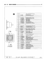
E5 20DG* WAIT-TO-START SWITCH
(SEE SH 7)
K31 20BK/PK* WATER-IN-FUEL
(SEE SH 8)
P5 20GY/BK* R.W.A.L. MODULE
P5 20GY/BK* PARK BRAKE WARNING SWITCH
(SEE SH 13)
AT1 180R ANTI-LOCK MODULE
(SEE SH 13)
G5 20DB* IGNITION- 12V FEED
(SEE SH 26)
P51 20BK/GY* IGNITION SWITCH GROUND
(BULB TEST)
(SEE SH 5)
H422BKGROUND(SEE SH 22)
P2 20BK/GY* BRAKE WARNING SWITCH &
VACUUM SWITCH
(SEE SH 13)
G40 20DB/RD* FUEL TANK
LOW FUEL SWITCH
(SEE SH 32)
H4>1 I SPLICE
P2 20BK/GY* R.W.A.L. MODULE
(SEE SH 13)
AD 25
MESSAGE CENTER (DIESEL)
J918W-13
WIRING DIAGRAMS
TO
OVERDRIVE SWITCH
AND MODULE
(SEE SH 6)
TO MESSAGE
CENTER
(SEE SH 24)
8W - 29
RED
T
G5
20DB X
s
TO4WD
< INDICATOR LAMP
(SEE SH 31)
G5 20DB *
-G5 2 0 D B *
G5 20DB * •
TO LEFT
PRINTED CIRCUIT
BOARD CONNECTOR
(SEE SH 52)
G5
20DBX
G5 20DB*
G5
20DBX
GRAY—\
2(0 0)1
-G5 20DBX-
a,
BLACK
TO
COMBINED
BUZZER
(SEE SH 32)
J2
14DB
TO RIGHT
PRINTED CIRCUIT
BOARD CONNECTOR
(SEE SH 52)
J918W-13
FUSE # 12
(5 AMP)
MESSAGE CENTER SPLICE (DIESEL)
TO IGNITION
SWITCH
(SEE SH 5)
AD 26
8W - 30
WIRING DIAGRAMS
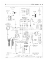
FUSE #1
(30 AMP)
NATURAL
C5 I6LG
TO I G N I T I O N N
SWITCH
7(SEE SH 5)
C6 MLB —[T] [T]— C3 12WT/DG*
-to
C7 12DG-
CI 12BR
•Q20 12BK/RD X—(•
12TN
-C4
NATURAL
C6 14LBC5 16LG-~-^t-c=] k
L
C7 12DG-
//
0FF
&"
t
10BR
C4 10TN
C3
12WT
DGX
12WT/DG X
BLACK--.
r. 10TN
C2 18DB/0RX-
O
Hi—@
L0 1
,V»
BLACK
"MED
•#
C7
12DG
BLOWER
MOTOR
RESISTOR
f 7
(UPPER RIGHT ipr)G
SIDEPLENUM)
CI
12BR
HI
HEATER
BLOWER
SWITCH
(INSTRUMENT
PANEL)
AIR CONDITIONER
AND HEATER
VACUUM SWITCH
(INSTRUMENT
PANEL)
C4
10TN
H4
18BK
C4 10TN — < (
CI
10BR
C7 12DG
C2
18DB
ORX
•C3 12WT/DGX-<(
C7 12DGBLACK
NATURAL
C7 12DG
(LEFT CENTER
OF INSTRUMENT
PANEL)
C9
14BK
1
—C9 12BK-
BLOWER
MOTOR
(RIGHT SIDE
DASH PANEL)
H4 18BK
C2 18DB/0RX
C7
12DG
TO <H4>2|SPLICE
-H4 18BK—^
V9
20BK
JO
CI
12BR
CI 10BR
(SEE SH 22)
nj#2
-C7 12DG
SPLICE
(SEE SH 18)
TO W A S H E R
MOTOR
(SEE SH 23)
AD 27
A/C & HEATER-DIESEL
ENGINE
J918W-13
8W - 31
WIRING DIAGRAMS
•
A/C COMPRESSOR
CLUTCH
(FRONT OF ENGINE
\
\
A/C LOW PRESSURE
SWITCH
\
(RIGHT FENDER
\
SIDE SHIELD)
\
\
TO
WIPER MOTOR
(SEE SH 23)
«
PROBE ,
(RIGHT
SIDE
SHIELD)
,
E3=
ELECTRONIC
CLUTCH
CYCLING
SWITCH
C20 18DB/0RX
J2 14DBC20 18BR-
C20 18DB/0R*
J918W-13
A/C & HEATER-DIESEL ENGINE
AD 28
8W - 32
WIRING DIAGRAMS
€
5
TO TRANSMISSION
WIRING
SEE SH 3)
TO <L7>1 SPLICE
(SEE SH 21)
TO TURN
SIGNAL SWITCH
(SEE SH 24)
CAB I
CHASSIS
LEFT
TAIL.
STOP t
TURN
SIGNAL
LAMP
LEFT
BACK-UP
LAMP
SWEPTLINE
BOX
LEFT
TAIL,
STOP t
TURN
SIGNAL
LAMP
TO <X25T|SPLICE
SEE SH 32)
LEFT
BACK-UP
LAMP
AD 29
B2 18VT/BK*-
REAR LIGHTING
J918W-13
WIRING DIAGRAMS
LICENSE
LAMP
WITHOUT
BUMPER
H4 18BK-
H4 18BK
(LEFT REAR /
FRAME R A I L ) /
LICENSE
LAMP
sftjU
L7 18BK/YL*
BLACK
X2 18GY
L7 18BK/YL*
8W - 33
LICENSE
LAMP
H4 18BK
STEP
BUMPER
L7 18BK/YL*
BLACK(CENTER OF REAR BUMPER)
L7 18BK
^
BLACK
LICENSE
LAMP
STANDARD
BUMPER
L7
18BK
YLX
BLACK
X2 18GY
X2
18GY-1
•L7 18BK/YLX
RIGHT
TAIL,
STOP 1
TURN
SIGNAL
LAMP
CAB I
CHASSIS
07 18BR/YLX
RIGHT
BACK-UP
LAMP
X2 18GY
B2 18VT/BK*
RIGHT
TAIL.
STOP I
TURN
SWEPTLINE
BOX
RIGHT
BACK-UP
LAMP
J918W-13-
REAR LIGHTING
AD 30
8W - 34
WIRING DIAGRAMS
•
G5
20DB*
J2 14DB
G5
20DB*
TO IGNITION
SWITCH
(SEE SH 5)
FUSE # 1 2
(5 AMP)
SPLICE
(SEE SH 26)
FOUR WHEEL
DRIVE INDICATOR
LAMP
X4
20LG
BRX
REAR WHEEL
ANTI-LOCK
C_
MODULE (SEE SH 13) >
X4 20LG/BRX-
nl#40
DIESEL ~
X4 20LG/BR %
DARK GRAY
(REAR OF
ENGINE)
s
TRANSFER
CASE
SWITCH
(DIESEL
ENGINE)
r^—
205 TRANSFER
CASE
-X4 20LG/BRX J
—X9 18BK—
BLACK
(ON TRANSFER
CASE)
T 0 < J 9 > 2 | SPLICE
(SEE SH 11)
AD
31
4 WHEEL DRIVE INDICATOR LAMP
J918W-13
WIRING DIAGRAMS
SW - 31
TO
IGNITION
SWITCH
( S E E SH 5 )
SEAT BELT
SWITCH
JH SEAT
BELT BUCKLE)
H4
, TO CARGO
18BK — 4
LAMP
(SEE SH 42)
GROUND
SPLICE
(SEE SH 2 2 )
SPLICE
( S E E SH 29)
J918W-13
5— X2
16GY
FUEL TANK SENDING
UNIT WITH LOW FUEL
LAMP SWITCH
DIESEL FUEL TANK GAUGE
AND SEAT BELT WARNING SYSTEM
AD 32
8W - 36
WIRING DIAGRAMS
CAVITY
SMALL
INDEX
50
49
48
47
46
1
45
44 43 42 41 40 39 38 37 36 35
34 33 32
28 27 26
22 21 20
©
31 30 29
25 24 23
19 18 17
16 15 14 13 12 11 10 9 8 7
6
5
4
3
2
LARGE
INDEX
TERMINAL END
OF DISCONNECT
AD 33
1
1
2
3
4
5
6
7
8
9
10
11
12
13
14
15
16
17
18
19
20
21
22
23
24
25
26
27
28
29
30
31
32
33
34
35
36
37
38
39
40
41
42
43
44
45
46
47
48
49
50
ENGINE COMPARTMENT CIRCUITS
L1 12RD*
C7 12DG
HEADLAMP SWITCH
A/C & HEATER BLOWER MOTOR
L4 16VT/WT *
L3 14RD/0R*
X30 20DB/RD*
X31 20BR/RD*
X33 20WT/LG •
X32 20YL/LG*
E5 20DG/WT *
L33 16RD/BK*
L20 14LG/BK *
HEADLAMP LOW BEAM (2 WIRES)
HEADLAMP HIGH BEAM (2 WIRES)
SPEED CONTROL
SPEED CONTROL
SPEED CONTROL
SPEED CONTROL
WAIT TO START LAMP
HIGH BEAM INDICATOR LAMP
HIGH BEAM FEED (DR.L. MODULE)
-
G20 20VT/YL*
G620GY
G60 20GY/YL*
D618LG
D5 18TN
A3 16PK
WATER TEMPERATURE SENDING UNIT
OIL PRESSURE SWITCH
OIL PRESSURE SENDING UNIT (DIESEL)
B2 18VT/BK*
L7 18BK/YL*
B1 18WT
BACK-UP LAMPS
PARKING LAMPS (2 WIRES)
BACK-UP LAMP SWITCH
_
LEFT TURN SIGNAL LAMP (2 WIRES)
RIGHT TURN SIGNAL LAMP (2 WIRES)
BATTERY-HAZARD FLASHER
V10 20BR
WINDSHIELD WASHER MOTOR
-S2 16YL*
_
H2 18DG/RD *
L22 18BK/RD *
P51 20GY/BK*
V5 18DG
V6 18DB
C20 18DB/0R*
K31 20BK/PK*
STARTER RELAY-IGNITION
HORN
UNDERHOOD LAMP
BRAKE WARNING LAMP SWITCH
WINDSHIELD WIPER MOTOR
WINDSHIELD WIPER MOTOR
AIR CONDITIONING DAMPED PRESSURE SWITCH
WATER IN FUEL LAMP
X4 20LG/BR *
D40 18WT/PK*
4 WHEEL DRIVE SWITCH
BRAKE SENSOR
G7 20WT/OR *
U4 200R/WT*
V3 18BR/WT*
V4 18RD/YL*
J2 14DB
C13 12BK/RD*
J1 12RD
J10 12PK*
SPEED SENSOR
OVERDRIVE LOCKOUT
WINDSHIELD WIPER MOTOR
WINDSHIELD WIPER MOTOR
SPLICE-IGNITION RUN CIRCUIT
IGNITION OFF DRAW
IGNITION SWITCH
IGNITION SWITCH
50-WAY BULKHEAD DISCONNECT
J918W-13
8W • 37
WIRING DIAGRAMS
CAVITY
1
2
3
4
5
6
7
8
9
10
11
12
13
14
15
16
17
18
19
20
21
22
23
24
25
26
27
28
29
30
31
32
33
34
35
36
37
38
39
40
41
42
43
44
45
46
47
48
49
50
J918W-13
INSTRUMENT PANEL CIRCUITS
L1 12RD*
C7 12DG
BATTERY FEED
A/C & HEATER BLOWER MOTOR
L40 16VT/WT*
L30 14RD/0R*
X30 20DB/RD*
X31 20BR/RD *
X33 20WT/LG *
X32 20YL/AD*
X32 20YL/RD *
E5 20DG/BK*
L33 16LG/BK*
L20 20LG/BK*
HEADLAMP - LOW BEAM
HEADLAMP-HIGH BEAM
SPEED CONTROL
SPEED CONTROL
SPEED CONTROL
G20 20VT/YL*
G620GY
G60 20GY/YL*
D6 18LG
D6 18LG
D5 18TN
D5 18TN
A3 16PK/WT *
SPEED CONTROL
WAIT TO START LAMP
HIGH BEAM INDICATOR LAMP
HIGH BEAM FEED (DRL MODULE)
TERMINAL END
OF DISCONNECT
TEMPERATURE-SEND/UNIT OR SWITCH
OIL PRESSURE LAMP
OIL PRESSURE GAUGE-SEND UNIT
-
r. .
I
47
48 | 49 50
4536 374638 39 40 41 42 43 44
35
LEFT FRONT TURN SIGNAL LAMP
29 30 31
23 24 25
RIGHT FRONT TURN SIGNAL LAMP
HAZARD FLASHER
17 18 19
(O)
32 33 34
26 27 28
20 21 22
7 8 9 10 11 12 13 14 15 16
B2 18VT/BK*
L7 18BK/YL*
B1 18WT
BACK-UP LAMPS
PARKING LAMPS
BACK-UP LAMP FEED
V10 20BR
WINDSHIELD WASHER MOTOR
_
-
X4 20LG/BR*
X4 20LG/BR*
D40 18WT/PK*
4 WHEEL DRIVE SWITCH
BRAKE SENSOR
S2 14YL
H2 18DG/RD*
L22 18BK/RD*
P51 20BK/GY •
V5 18DG
V6 18DE
C2 18DB/0R*
K31 20BK/PK*
G7 20WT/0R*
U4 200R/WT*
V3 18BR*
V4 18RD/YL*
J2 14DB
J2 14DB
C13 12BK/RD*
J1 12RD
J10 12PK*
I
IGNITION START
HORNS
UNDERHOOD LAMP
BRAKE WARNING LAMP SWITCH
WINDSHIELD WIPER SWITCH
WINDSHIELD WIPER SWITCH
A/C CLUTCH
WATER IN FUEL LAMP (DIESEL ONLY)
2
3
4
5
6
LARGE
INDEX
SPEED SENSOR (2 WIRES)
OVERDRIVE LOCKOUT SWITCH
WINDSHIELD WIPER LOW SPEED
WINDSHIELD WIPER HIGH SPEED
IGNITION-RUN & START
BATTERY FEED
IGNITION SWITCH (B1)
IGNITION SWITCH (B3)
50-WAY BULKHEAD
DISCONNECT
AD 34
8W - 38
WIRING DIAGRAMS
CAV
1
IGNITION SYSTEM CIRCUITS
K32 20TN/BK *
WATER-IN-FUEL SENSOR
SHEET
8
2
J11 16RD
DIRECT BATTERY
9
SENSOR RETURN
10
5
N5 18BK/L8*
K5 16BK*
SIGNAL GROUND
8
6
K8 20VT/WT *
5 VOLT SUPPLY
10
8
S518BR
START SIGNAL
8
9
J2 14DB
IGNITION FEED
8
10
U4 20RD/WT*
OVERDRIVE LOCKOUT CONTROL
6
11
J918LB/RD*
POWER GROUND
10
12
J918LB/RD*
_
POWER GROUND
_
10
_
15
S22 180R/BK*
HEATER #2 RELAY
8
16
S21 18YL*
_
HEATER #1 RELAY
_
8
3
4
7
13
14
17
18
-
19
20
SHORT TAB
21
S2018LB*
INTAKE AIR TEMPERATURE
8
22
K7180R/DB*
THROTTLE POSITION SENSOR
10
23
24
K718 0R/DB*
THROTTLE POSITION SENSOR
10
25
DK21 -20PK
-
SCI TRANSMIT
10
-
D40 18WT/PK*
S4 20BR/YL*
_
BRAKE SENS!
PARK/NEUTRAL SWITCH
9
_
X36 20TN/RD *
SPEED CONTROL-VACUUM
15
37
-
-
-
38
_
39
_
-
_
42
-
_
_
43
_
-
-
46
DK20 20LG
_
SCI RECEIVE
_
10
_
47
G7 20WT/OR *
SPEED SENSOR PICKUP
9
48
X31 20BR/RD*
SPEED CONTROL-SET
15
49
X32 20YL/RD *
SPEED CONTROL-ON/OFF
15
50
X33 20WT/LG *
SPEED CONTROL-RESUME
15
26
-
27
28
29
30
31
9,15
32
I
i i I i I i i I i 1/
33
34
35
LONG
VIEWED FROM WIRE
END OF CONNECTOR
TAB
36
40
41
44
45
51
52
53
X35 20LG/RD *
SPEED CONTROL-VENT
15
54
K31 20BK/PK
WATER-IN-FUEL LAMP
8
55
V40 20OR/LG*
OVERDRIVE LOCKOUT SOLENOID
6
56
E5 20DG*
57
8
-
58
-
WAIT-TO-START LAMP
_
59
_
-
-
_
60
AD 35
SINGLE BOARD
ENGINE CONTROLLER CONNECTOR (DIESEL)
J918W-13
5 J L (DIESEL) ENGINES
9- 1
5 J L DIESEL ENGINES
CONTENTS
page
ENGINE DIAGNOSIS ...................... 3
ENGINE SERVICE PROCEDURES .......... 12
page
GENERAL INFORMATION
1
GENERAL INFORMATION
The 5.9 Liter (359 CID) Cummins Turbocharged/Intercooled six-cylinder diesel engine is an In-line
valve-in head type (Fig. 1). The cylinder block and
head are cast iron.
This engine is designed for No, 2 Diesel Fuel. Only
use No. 1 Diesel Fuel where extended arctic conditions exist (below -23°C or ~10°F).
The cylinders are numbered from front to rear (1,
2, 3, 4, 5 and 6). The firing order is 1-5-3-6-2-4 (Fig.
2).
• "
1 —5—3—^-2—4 .
0 0 0 0 0 O
J898D-10
Fig.
2 Engine
Firing
Order
Engine lubrication system consists of a gerotor
type oil pump and a full flow oil filter with a bypass
valve.
Fig.
1 Six-Cylinder
In-line
Engine
9 •2
5.9L (DIESEL) ENGINES
ENGINE
Type
Bore and Stroke
Displacement
Compression Ratio
Engine Torque
Firing Order
Lubrication
Engine Oil Capacity
Cooling System
Cooling Capacity (Auto Trans)
(Manual Trans)
Coolant Recovery Tank
Cylinder Block
Crankshaft
Cylinder Head
Combustion Chambers
Camshaft
Pistons
Connecting Rods
•
DESCRIPTION
5,9L DIESEL
ENGINES
In-line 6
102 x 120 mm
(4.02 x 4.72 Inch)
5.9 Liters
(359 cubic inches)
17.5:1
542 N » m (400 ft. lbs.) @ 1750 rpm
1-5-3-6-2-4
Pressure feed-Full Flow Filtration
with Bypass Filter
11.4 Liters
(12 Quarts)
Liquid Cooled-Forced Circulation
16.2 Liters
• (17 Quarts!
15.2 Liters
(16 Quarts)
0.95 Liter
(1.0 Quart)
Cast Iron
Induction Hardened-Forged Steel
Cast Iron
High Swirl Combustion Bowl
Chilled Cast Iron
Cast Aluminum
Forged Steel
J9109-255
5.9L (DIESEL) ENGINES
•
9- 3
ENGINE DIAGNOSIS
GENERAL INFORMATION
Refer to the Service Diagnosis-—Mechanical Chart
and the Service Diagnosis—Performance Chart for
possible causes and corrections of malfunctions. Refer
to Group 14, Fuel System for the fuel system diagnosis.
Engine diagnosis is helpful in determining the
causes of malfunctions not detected and remedied by
routine tune-ups.
These malfunctions may be classified as either mechanical (e.g., a strange noise), or performance (e.g.,
engine idles rough and stalls).
SERVICE
CONDITION
LUBRICATING OIL
PRESSURE LOW
DIAGNOSIS
-
MECHANICAL
CORRECTION
POSSIBLE CAUSES
Low oil level.
(a) Check and fill with clean engine oil.
(b) Check for a severe external oil leak that could reduce the
pressure.
Oil viscosity thin, diluted or
wrong specification.
Verify the correct oil is being used. Check for oil dilution. Refer
to Contaminated Lube Oil (Engine Diagnosis—Mechanical).
Improperly operating pressure
switch/gauge.
Verify the pressure switch is functioning correctly. If not.
replace switch/gouge.
Relief valve stuck open.
Check/replace valve.
Plugged oil filter.
Change oil filter. Oil filter change interval may need to be
revised.
If cooler was replaced, shipping
plugs left in cooler.
Check/remove shipping plugs.
If pump replaced, four cylinder
oil pump installed in a six
cylinder engine.
Verify that the correct pump is installed. If not, install an oil
pump for a six cylinder engine.
Loose or missing cup plugs.
Check and replace cup plugs.
Worn oil pump.
Check and replace oil pump.
Suction tube loose or seal
leaking.
Check and replace seal.
Loose main bearing cap.
Check and install new bearings and tighten cap to proper torque.
Worn bearings or wrong
bearings installed.
Inspect and replace connecting rod or main bearings. Check and
replace piston cooling nozzles.
J9109-237
9 -4
5.9L (DIESEL) ENGINES
SERVICE
CONDITION
LUBRICATING OIL
PRESSURE TOO HIGH
LUBRICATING OIL LOSS
DIAGNOSIS
POSSIBLE CAUSES
• MECHANICAL
(CONT.J
CORRECTION
Pressure switch/gauge not
operating properly.
Verify the pressure switch is functioning correctly. If not,
replace switch/gauge.
Engine running too cold.
Refer to Coolant Temperature Below Normal (Engine Diagnosis—
Performance)
Oil viscosity too thick.
Make sure the correct oil is being used. Refer to Group O,
Lubrication and Maintenance.
Oil pressure regulator valve
stuck closed or binding.
Check and replace valve, and/or oil cooler cover.
External leaks.
Visually inspect for oil leaks. Repair as required.
Crankcase being overfilled.
Verify that the correct dipstick is being used.
Incorrect oil specification or
viscosity.
(a) Make sure the correct oil is being used.
(b) Look for reduced viscosity from dilution with fuel.
(c) Review/reduce the oil change intervals.
COMPRESSION
KNOCKS
Oil cooler leak.
Check and replace the oil cooler.
High blow-by forcing oil out
the breather.
Check the breather tube area for signs of oil loss. Perform the
required repairs.
Turbocharger leaking oil to the
air intake.
Inspect the air ducts for evidence of oil transfer.
Repair as required.
Worn valve seals.
Inspect and replace the valve seals.
Piston rings not sealing (oil
being consumed by the engine).
Perform blow-by check. Repair as required.
Air in the fuel system.
Bleed the fuel system (refer to Group 14, Fuel System).
Poor quality fuel.
Verify by operating from a temporary tank with good fuel. Clean
and flush the fuel supply tanks. Replace fuel/water separator
filter.
Engine overloaded.
Verify that engine load rating is not being exceeded.
Incorrect injection pump timing.
Check and time injection pump (refer to Group 14, Fuel System).
Improperly operating injectors.
Check and replace inoperative injectors.
J9109-266
•
5.9L (DIESEL) ENGINES
SERVICE
CONDITION
EXCESSIVE VIBRATION
DIAGNOSIS
• MECHANICAL
9- 5
(CONT.)
CORRECTION
POSSIBLE CAUSES
Loose or broken engine mounts.
Replace engine mounts.
Damaged fan or improperly
Check and replace the vibrating components.
operating accessories.
Improperly operating vibration
Inspect/replace the vibration damper.
damper.
EXCESSIVE ENGINE
NOISES
Improperly operating fan hub.
Inspect/replace the fan hub.
Worn or damaged alternator
bearing.
Check/replace the alternator.
Flywheel housing misaligned.
Check/correct flywheel alignment.
Loose or broken power
component.
Inspect the crankshaft and rods for damage that causes an
unbalance. Repair/replace as required.
Worn or unbalanced driveline
components.
Check/repair driveline components.
Drive belt squeal, insufficient
tension or abnormally high
loading.
Check the tensioner and inspect the drive belt. Make sure water
pump, tensioner pulley, fan hub and alternator turn freely.
Intake air or exhaust leaks.
Refer to Excessive Exhaust Smoke (Engine Diagnosis—
Performance).
Excessive valve lash
Adjust valves. Make sure the push rods are not bent and rocker
levers or adjusting screws are not severely worn. Replace bent
or severely worn pads.
Turbocharger noise.
Check turbocharger impeller and turbine wheel for housing
contact. Repair/replace as required.
Gear train noise.
Visually inspect and measure gear backlash. Replace gears as
required.
Power function knock.
Check/replace rod and main bearings.
ALTERNATOR NOT
Loose or corroded battery
CHARGING OR INconnections.
SUFFICIENT CHARGING
Alternator belt slipping.
Clean/tighten battery connection.
Check/replace belt tensioner. Check/replace belt.
Alternator pulley loose on
shaft.
Tighten pulley.
Improperly operating
alternator.
Check/replace alternator.
J9109-253
9 -6
•
5.9L (DIESEL) ENGINES
SERVICE
CONDITION
ENGINE WILL NOT
CRANK OR CRANKS
SLOWLY
ENGINE CRANKS,
BUT WILL NOT
START—NO SMOKE
FROM EXHAUST
ENGINE HARD TO
START, OR WILL
NOT START—SMOKE
FROM EXHAUST
DIAGFdQSIS
-
PERFORMANCE
CORRECTION
POSSlBLi CAUSES
Starting motor operating, but
not cranking the engine.
Remove the starter motor. Check for broken flywheel teeth or
a broken starting motor spring.
Crankshaft rotation restricted.
Rotate the engine to check for rotational resistance.
Starting circuit connections
loose or corroded.
Clean and tighten connections.
Neutral safety switch or starter
relay inoperative.
Check starter relay for supply voltage and proper operation of
neutral safety. Replace defective parts.
Battery charge low.
Check battery voltage. Replace battery if a charge cannot be
held.
No voltage to starter solenoid.
Check voltage to solenoid. If necessary, replace the solenoid.
Solenoid or starting motor
inoperative.
Replace starter motor.
No fuel in supply tank.
Fill fuel supply.
Electrical fuel shutdown not
open.
Check for loose wires and verify that the valve is functioning.
Check to be sure manual shutoff lever is in the run position.
Air intake or exhaust plugged.
Remove the obstruction.
Fuel filter plugged.
Drain fuel/water separator and replace fuel filter.
Injection pump not getting fuel
or fuel is aerated.
Check fuel flow/bleed fuel system.
Worn or inoperative injection
pump.
Visually check fuel delivery with an externally connected
injector to one of the pump outlets. Replace the pump if fuel
is not being delivered.
Internal pump timing incorrect.
Time the pump (refer to Group 14, Fuel System).
Camshaft out of time.
Check/correct gear train timing alignment.
Incorrect starting procedure.
The manual fuel shutoff control must be in the run position.
Cranking speed too slow.
(a) Verify that the transmission is not engaged.
(b) Check the battery, starting motor and look for loose or
corroded wiring connections.
(c) Rotate the engine with a barring tool (Snap-On Tool SP371,
MTE No. 3377462, or equivalent) to check for internal
rotational resistance.
Cold starting aids not working
or are needed.
Verify the aids are operating. Repair/replace inoperative
parts.
Intake heater system not
working.
Verify system is working. Repair/replace inoperative parts.
Insufficient intake air.
Inspect or replace filter and check for obstructions to the air
supply tube.
Air in the fuel system or the
fuel supply is inadequate.
Check the flow through the filter and bleed the system. Locate
and eliminate the air source.
J9109-232
5.9L (DIESEL) ENGINES
SERVICE
DIAGNOSIS
- PERFORMANCE
ENGINE STARTS,
BUT WILL NOT
KEEP RUNNING
SURGING (SPEED
CHANGE)
ROUGH IDLE
(IRREGULARLY FIRING
OR ENGINE SHAKING)
(CONT.)
C01RECTION
POSSIBLE CAUSES
ENGINE HARD TO
START, OR WILL
NOT START—SMOKE
FROM EXHAUST
(Cont'd)
9- 7
Fuel pump inoperative.
Disconnect fuel line and verify fuel delivery. If needed replace
pump.
Injection pump throttle linkage
loose or damaged.
Visually check the linkage. Tighten/replace linkage.
Contaminated fuel.
Verify by operating the engine with clean fuel from a
temporary tank. Check for presence of gasoline. Drain and
flush fuel supply tanks. Replace fuel/water separator filter.
Worn or inoperative injection
pump.
Visually check fuel delivery with an externally connected
injector to one of the pump outlets. Replace the pump if fuel is
not being delivered.
Injection pump out of time.
Check/time the pump (refer to Group 14, Fuel System).
Valves incorrectly adjusted.
Adjust valves.
One or more injectors worn or
not operating properly.
Check/replace bad improperly operating injectors.
Idle speed too low for the,
accessories.
Adjust the idle speed.
Intake air or exhaust system
restricted.
Visually check for exhaust restriction and inspect the air intake.
Repair/replace restricting parts.
Air in the fuel system or the
fuel supply is inadequate.
Check the flow through the filter and bleed the system. Locate
and eliminate the air source.
Fuel waxing due to extremely
cold weather.
Verify by inspecting the fuel filter. Clean the system and use
climatized fuel. Replace fuel/water separator filter. Check fuel
heater for proper operation.
Contaminated fuel.
Verify by operating the engine with clean fuel from a temporary
supply tank. Check for presence of gasoline. Replace fuel/water
separator filter.
If the condition occurs at idle,
the idle speed is set too low for
the accessories.
Adjust the idle.
High pressure fuel leak.
Inspect/correct leaks in the high pressure lines. Fittings and
delivery valve sealing washers.
One or more injectors worn or
not operating properly.
Check/replace the inoperative injectors.
Improperly operating injection
pump.
Replace the injection pump.
Cold engine.
Refer to troubleshooting logic for intake manifold heater system
(see Group 11, Exhaust System & Intake Manifold)
Idle speed too low for the
accessories.
Adjust idle speed.
Engine mounts damaged or
loose.
Repair or replace mounts.
J9109-233
SERVICE
CONDITION
ROUGH IDLE
(IRREGULARLY FIRING
OR ENGINE SHAKING)
(Cont'd)
ENGINE RUNS ROUGH
OR MISFIRING
DIAGNOSIS
- PERFORMANCE
POSSIBLE CAUSES
(GGNT.)
COKKBCTSON
High pressure fuel leaks.
Correct leaks in the high pressure lines, fittings or delivery
valves.
Air in the fuel system.
Bleed the fuel system and eliminate the source of the air.
Sticking needle valve in an
injector.
Check and replace the injector with the sticking needle valve.
Fuel injection lines leaking.
Correct leaks in the high pressure lines, fittings, injector sealing
washers or delivery valves.
Air in the fuel or the fuel
supply is inadequate.
Check the flow through the filter and bleed the system. Locate
and eliminate the air source.
Contaminated fuel.
Verify by operating the engine with clean fuel from a temporal,
supply tank. Check for presence of gasoline. Replace fuel/water
separator filter.
Incorrect valve adjustment.
Check for a bent push rod and adjust valves. Replace push rod,
if necessary.
ENGINE RPM WILL NOT
REACH RATED SPEED
Injection pump timing incorrect.
Check/time pump (refer to Group 14, Fuel System).
Improperly operating injectors.
Replace inoperative injectors.
Defective injection pump
(delivery valves).
Replace injection pump.
Camshaft out of time.
Check/correct gear train timing alignment.
Damaged camshaft or tappets.
Inspect camshaft valve lift. Replace camshaft and tappets.
Engine overloaded.
Verify high idle speed without load. Investigate operation to be
sure correct gear is being used.
Improperly operating
tachometer.
Verify engine speed with hand tachometer-—correct as required.
Throttle linkage worn or
incorrectly adjusted.
Adjust linkage for stop-to-stop fuel control lever travel. Replace
Partially engaged mechanical
shutdown lever.
Adjust and place shutdown lever in the run position.
Inadequate fuel supply.
Check the fuel flow through the system to locate the reason for
linkage if necessary.
inadequate fuel supply—correct as required.
LOW POWER
Improperly operating injection
pump.
Replace injection pump.
Fuel control lever not moving to
full throttle.
Check/correct for stop-to-stop travel.
Mechanical/shutdown lever
partially engaged.
Check to see if the shutdown lever is in run position.
High oil level.
Check/correct oil level.
Engine overloaded.
Check for added loading from accessories or driven units, brakes
dragging and other changes in vehicle boding. Repair/replace as
needed.
J9109-264
•
— • — — — — — — —
SERVICE
CONDITION
LOW POWER
(Cont'd)
DIAGNOSIS
• PERFORMANCE
9- 9
(CON7.)
CORRECTION
POSSIBLE c a y s s s
Slow throttle response, leaking
air fuel control tube or
5.9L (DIESEL) ENGINES
Tighten the fittings. Replace the pump if the controls are not
functioning.
improperly operating control :
in the pump.
EXCESSIVE EXHAUST
SMOKE
Incorrect external injection
pump timing.
Verify that injection pump timing marks are aligned (see Group
14, Fuel System).
'
Inadequate intake air flow.
Inspect/replace air cleaner element. Look for other restrictions.
High pressure fuel leak.
Inspect/correct leaks in the high pressure lines, fittings injector
sealing washers or delivery valve* seals.
Inadequate fuel supply.
Check the flow through the filter to locate the source of the
restriction.
High fuel temperature.
Verify that fuel heater is off during warm weather. Check for a
restricted fuel drain manifold. Repair/replace as needed.
Poor quality fuel or fuel
contaminated with gasoline.
Verify by operating from a temporary tank with good fuel.
Check for presence of gasoline. Replace fuel/water separator
filter.
• '
-•*
Air leak between the turbocharger and the intake
manifold.
Check/correct leaks in the air tubes, intercooler, hoses, gaskets,
and around mounting capscrews or through holes in the manifold
cover.
Intercooler blocked.
Check pressure drop across intercooler (4" of Hg. max. @ rated
power).
Exhaust leak at the manifold
or turbocharger.
Check/correct leaks in the manifold or turbocharger gaskets.
If manifold is cracked, replace manifold.
Improperly operating turbocharger.
Inspect/replace turbocharger.
Valve clearance incorrect.
Check/adjust valves.
Injection pump improperly
operating.
Check/time pump (refer to Group 14, Fuel System).
Worn or improperly operating
injectors.
Check/replace injectors.
Improperly operating injection
pump.
Replace injection pump.
Excessive exhaust restriction.
Check/correct the restriction in the exhaust system.
Engine running too cold (white
smoke).
Refer to troubleshooting logic for coolant temperature below
normal (refer to Group 14, Cooling System). Inspect intake
manifold heater/KSB valve for proper operation.
Inadequate intake air.
Inspect/change air cleaner. Look for other restriction.
Air leak between turbocharger
and intake manifold.
Check/correct leaks in the air tubes, intercooler, hoses, gaskets,
mounting capscrews or through holes in the manifold cover.
Intercooler blocked.
Check pressure drop across intercooler (4" of Hg. max. @ rated
power).
Exhaust leak at the manifold
or turbocharger.
Check/correct leaks in the manifold or turbocharger gaskets.
If cracked replace manifold.
Improperly operating
turbocharger.
Inspect/replace turbocharger.
|
J9109-265
9 - 10
5.9L (DIESEL) ENGINES
SERVICE
CONDITION
EXCESSIVE EXHAUST
SMOKE (Cont'd)
ENGINE WILL NOT
SHUT-OFF
DIAGNOSIS
• PERFORMANCE
(CONT.)
CORRECTION
POSSIBLE CAUSES
More than one sealing washer
under an injector.
Check and remove extra washer.
Improperly operating injectors.
Check and replace inoperative injectors.
Improperly operating or overfueled injection pump.
Replace injection pump.
Piston rings not sealing
(blue smoke).
Perform blow-by check. Correct as required.
Fuel shutoff valve inoperative.
Stop the engine mechanically with lever on the fuel pump.
Check/replace sealing washer, piston and spring.
Engine running on fumes drawn
into the air intake.
Check the air intake ducts for the source of the fumes.
TO STOP AN ENGINE THAT IS RUNNING ON FUEL SOURCES
OTHER THAN THE DIESEL FUEL INJECTION SYSTEM, SPRAY A FIRE
EXTINGUISHER INTO THE AIR INTAKE SYSTEM. THE AIR PICKUP IS
LOCATED BELOW THE RIGHT HEAD LIGHT (PASSENGER SIDE)
BEHIND THE BUMPER.
COOLANT TEMPERATURE ABOVE NORMAL
Low coolant level.
(a) Check coolant level. Add coolant, if necessary.
(b) Locate and correct the source of the coolant leak. Refer to
troubleshooting logic for coolant loss.
Incorrect/improperly operating
pressure cap.
Replace cap with the correct rating for the system.
High lube oil level.
Check/drain oil to correct level.
Loose drive belt on water
pump/fan.
Check/replace belt or belt tensioner.
Inadequate air flow to the
radiator.
Check/repair radiator core, fan shroud and fan clutch as
required.
Radiator fins plugged.
Blow debris from fins.
Collapsed radiator hose.
Replace the hose.
Improperly operating temperature sensor/gauge.
Verify that the gauge and temperature sensor are accurate.
Replace gauge/sensor, if bad.
Improperly operating, incorrect
or no thermostat.
Check and replace the thermostat.
Air in the cooling system.
(a) Make sure the fill rate is not being exceeded and the correct
vented thermostat is installed.
(b) Check for loose hose clamps. Tighten if loose.
(c) If aeration continued, check for a compression leak through
the head gasket.
Inoperative water pump.
Check and replace the water pump.
Incorrect injection pump timing.
Verify pump timing marks are aligned. Check/time the injector
pump (refer to Group 7, Cooling System).
J9109-236
5.9L (DIESEL) ENGINES
SERVICE
CONDITION
COOLANT TEMPERATURE ABOVE NORMAL
(Cont'd)
COOLANT TEMPERATURE BELOW NORMAL
DIAGNOSIS
- PERFORMANCE
9 - 11
(CONT.)
CORRECTION
POSSIBLE CAUSES
Overfueled infection pump.
Replace the injection pump.
Plugged cooling passages in
radiator, head, head gasket or
block.
Flush the system and fill with clean coolant.
Engine overloaded.
Verify that the engine load rating is not being exceeded.
Too much air flow across the
radiator.
Check/repair viscous fan as required.
Incorrect thermostat, broken
thermostat jiggle pin or
contamination in thermostat.
Check and replace thermostat.
Temperature sensor or gauge
inoperative.
Verify that the gauge and sensor are accurate. If not, replace
gauge/sensor.
Coolant not flowing by
temperature sensor.
Check and clean coolant passages.
J9109-254
INSPECTION (ENGINE OIL LEAKS)
If an oil leak source is not readily identifiable, the
following steps should be followed:
(1) Attach an air hose with pressure gauge and
regulator to the dipstick tube.
(2) Disconnect the breather cap to air cleaner hose
at the breather cap end. Cap or plug breather cap
nipple.
(3) Remove the PCV valve from the cylinder head
cover. Cap or plug the PCV valve grommet.
(4) After the engine is sealed, set the air pressure
regulator NO HIGHER than 27 kPa (4 psi).
(5) Using a liquid soap solution or preferable a
stethoscope, inspect all suspected oil leak areas. If an
oil leak area is detected, repair per the service manual instructions.
(6) If no leaks are detected, turn off the air supply
and remove the air hose and all plugs. Install the
PCV valve and breather cap hose. See step 7 and
check for higher pressure leaks occurring during normal engine operation.
(7) Clean the oil off the suspect oil leak area using
a suitable solvent. Drive the vehicle at various
speeds approximately 24 km (15 miles). Check the
engine for signs of an oil leak. If an oil leak is found,
repair per the service manual instructions.
(8) If the leakage occurs at the crankshaft rear oil
seal:
(a) Raise the vehicle.
(b) Remove torque converter or clutch housing
cover and inspect rear of block for evidence of oil.
A circular spray pattern generally indicates seal
leakage. Where leakage tends to run straight
down, possible causes are a porous block and the
rear cam and galley plugs. See Group 9, Engines
(Rear Main Bearing Oil Seals), for the proper seal
(and retainer) installation.
(c) If no leaks are detected while the crankcase is
pressurized 27 kPa (4 psi), very slowly turn the
crankshaft and watch for leakage. If a leak is detected while turning the crankshaft, its possible
the crankshaft seal surface is damaged in the seal
area, minor nicks or scratches can be polished out
with emery cloth.
ENGINE OIL PRESSURE
(1) Remove oil pressure sending unit.
(2) Install Oil Pressure Line and Gauge Tool
C-3292.
(3) Start engine and record pressure (refer to Oil
Pressure in Engine Specifications for the proper pressures).
9 - 12
5.9L (DIESEL) ENGINES
ENGINE S E R V I C E P R O C E D U R E S
INDEX
page
Cylinder Head
Engine Assembly .
Oil Cooler Element/Gasket
Oil Pressure Regulator Valve/Spring
Oil Pump
17
. 12
19
19
19
Piston Cooling Nozzles
Piston/Connecting Rod Assembly
Rocker Levers/Push Rods
Specifications—5.9L Diesel Engines
page
19
19
15
20
ENGINE ASSEMBLY
REMOVAL
(1) Disconnect the electrical connection into the
hood. Scribe the hood hinge bolt locations and remove the hood (Fig. 1).
Fig.
1 Scribe
Hood
Hinge
(2) Disconnect the battery cables and remove the
battery.
(3) Drain the coolant from the cooling system (refer
to Group 7, Cooling System for the proper procedures). Do not waste reusable coolant. If the solution
is clean, drain the coolant into a clean container for
reuse.
(4) Disconnect the radiator hoses. Remove the fan
shroud, fan/fan clutch assembly and radiator (refer to
Group 7, Cooling Systems for the proper procedures).
(5) Disconnect the heater hoses at the dash panel
and at the water valve (Fig. 2).
(6) Disconnect the air inlet tube from the turbocharger (Fig. 3) and the air intake housing. Remove
the tube.
Intel Tube and Exhaust Pipe
Connection
(8) Disconnect the intercooler inlet duct from the
turbocharger and the intercooler (Fig. 4). Remove the
inlet duct.
(9) Disconnect the intercooler outlet duct from the
air inlet housing and the intercooler (Fig. 4). Remove
the outlet duct.
Fig. 3 Air
5.9L (DIESEL) ENGINES
Fig.
4 Intercooler
Ducts
Fig.
8 Accelerator/Speed
Control/Throttle
I - 13
Valve
Linkage
(10) Remove the drive belt. Disconnect the alternator ground wire. Remove the alternator and set aside
(Fig, 5).
J91 09-1 13
Fig.
Fig,
5 Alternator
Removal
(11) Remove the A/C compressor and set aside. The
A/C compressor is located below the alternator.
(12) Disconnect the accelerator linkage, the speed
control linkage and the throttle valve linkage (Fig.
6).
(13) Raise and support the vehicle on a hoist.
(14) Drain the engine lubricating oil. Dispose of the
oil according to all applicable regulations.
(15) Disconnect the exhaust pipe steady rest clamp
and remove.
(16) Disconnect the starter connections (Fig. 7).
(17) Disconnect the transmission cooler lines.
7 Starter
Connections
(18) MANUAL TRANSMISSION-See Group 21,
Transmissions for the G360 Manual Transmission
Removal procedure.
(19) AUTOMATIC TRANSMISSION
(a) Remove torque converter bolt access cover.
(b) Mark torque converter and drive plate for assembly alignment (Fig. 8). Note that bolt holes in
crankshaft flange, drive plate and torque converter
all have one offset hole.
(c) Rotate crankshaft in clockwise direction until
converter bolts are accessible. Then remove bolts
one at a time. Rotate crankshaft with socket
wrench on damper pulley bolt.
(d) Support the transmission.
(e) Remove bell housing bolts and inspection
plate.
(20) Lower the vehicle.
(21) Disconnect the power steering lines.
(22) Disconnect the vacuum pump lines.
I
- 14
5.9L (DIESEL) ENGINES
CAUTION: When removing the engine, take care not
to damage the wiper motor and voltage regulator
mounted on the dash panel ( F i g . 10).
Fig.
10 Vifiper Motor/Voltage
Regulator
(28) Lift the engine out of the vehicle (Fig. 11).
Fig.
8 Marking
Converter
Alignment
and Drive
Reference
Plate
for
ENGINE
(23) Disconnect all electrical connections from the
engine. Put tags on the connections to identify their
locations.
(24) Disconnect the fuel lines to the lift pump and
fuel return. Use tags to identify the lines (Fig. 9).
Fig.
9 Lift
Pump
and Fuel
Lines
(25) Put a cover or tape over all engine openings.
(26) Make sure that the lifting brackets are
mounted with the eye up. If not, remove the bracket
and install in the proper position. Tighten the lifting
bracket bolts to 77 N-m (57 ft. lbs.) torque.
(27) Use the lifting brackets to apply tension to the
engine. Remove the engine mount through-bolts from
the cylinder block mounting bracket.
J9109-11
Fig.
11 Lifting
Engine
from
Vehicle
(29) Install the engine on a suitable stand.
(30) Remove all accessories and brackets not previously removed for use with the replacement engine.
5.9L (DIESEL) ENGINES
INSTALLATION
(1) If removed, install and tighten the rear engine
lifting bracket to 77 N-m (57 ft. lbs.) torque. Do not
exceed this torque valve.
(2) Check the data plate to verify that the replacement engine is the same model and rating as the engine that was removed.
(3) Install all accessories and brackets that had
been removed from the previous engine.
(4) Use the lifting brackets to lift the engine off of
the stand.
(5) Position the' engine in the chassis and install
the through bolt. Tighten the through bolt nut to 41
N-m (30 ft. lbs.) torque.
(6) Remove the covers or tape covering the engine
openings.
- (7) Connect the fuel lines to the lift pump and fuel
return.
(8) Connect all electrical connections.
(9) Connect the power steering lines.
(10) Raise and support the vehicle on a hoist.
(11) MANUAL TRANSMISSION-See Group 21,
Transmissions for the G360 Manual Transmission Installation procedure.
(12) AUTOMATIC TRANSMISSION
CAUTION; If new flei plate is installed, remove
flashing from the engine back plate at the 5 and 7
o'clock positions.
(a) Rotate converter until alignment mark on the
converter is aligned with mark on drive plate. Offset holes in plate are next to 1/8 inch hole in inner
circle of drive plate (Fig. 8).
(b) Install bell housing bolts. Tighten the bolts to
41 N-m (30 ft. lbs.) torque.
(c) With the torque converter plate aligned to the
torque converter, install and tighten the bolts to 31
N-m (270 in. lbs.) torque.
(d) Install the converter housing access plate.
(e) Remove the transmission support.
(13) Connect the ground cable and tighten the nut
to 22 N m (16 ft. lbs.) torque. Connect the solenoid
cable and tighten the nut to 5 N-m (44 in. lbs.)
torque.
(14) Connect the transmission cooler lines.
(15) Install the exhaust pipe to the exhaust system.
(16) Lower the vehicle.
(17) Install the A/C compressor and tighten the
bolts to 47 N m (35 ft. lbs.) torque. If removed, connect the clutch electrical wire.
(18) Install the alternator. Tighten the upper
mounting bolts to 24 N-m (18 ft. lbs.) torque. Now
tighten the lower mounting bolts to 43 N-m (32 ft.
lbs.) torque. Connect all wires.
#
#
9 - 15
(19) Install the radiator, fan/fan clutch assembly
and fan shroud (refer to Group 7, Cooling Systems
for the proper procedures). Connect the radiator
hoses.
(20) Position the intercooler inlet duct to the turbocharger and the intercooler (Fig. 4). With the clamps
in position, tighten the clamp nut to 8 N-m (72 in.
lbs.) torque.
(21) Position the intercooler outlet duct to the air
inlet housing and the intercooler (Fig. 4). With the
clamps in position, tighten the clamp nut to 8 N-m
(72 in. lbs.) torque.
(22) Connect the air intake tube to the turbocharger inlet flange and the air cleaner housing.
Tighten the clamps to 8 N-m (72 in. lbs.) torque.
(23) Install the exhaust pipe to the turbocharger.
Tighten the steady rest clamp to 8 N-m (72 in. lbs.)
torque.
(24) Make sure the air intake and exhaust pipe
connections are tight and free of leaks.
(25) Fill the engine with the required amount of
clean engine lubricating oil (see Group 0, Lubrication
and Maintenance).
(26) Fill the cooling system with a mixture of 50%
water and 50% ethylene-glycol base antifreeze (refer
Group 7, Cooling System for the proper procedure).
(27) Install the battery and connect the battery cables.
(28) Check the oil level after the engine has run for
2 or 3 minutes. Oil held in the oil filter and oil passages will cause the oil level in the pan to be lower.
(29) Operate the engine at idle for 5 to 10 minutes
and check for leaks and loose parts.
ROCKER LEVERS/PUSH RODS
REMOVAL
(1) Remove the valve covers (Fig. 1).
(2) Loosen the adjusting screw locknuts. Loosen the
adjusting screws until they stop (Fig. 2).
(3) Remove the bolts from the rocker lever pedestals. Remove the pedestals and rocker lever assemblies (Fig. 2).
(4) Remove the push rods.
DISASSEMBLE-ROCKER
LEVERS
(1) Remove the retaining rings and thrust washers
(Fig. 2).
(2) Remove the rocker levers (Fig. 2). Do not disassemble the rocker lever shaft and pedestal. The pedestal and shaft must be replaced as an assembly.
(3) Remove the locknut and adjusting screw (Fig.
2).
(4) Clean all parts in a strong solution of laundry
detergent in hot water.
(5) Use compressed air to dry the parts after rinsing in clean hot water. The pedestals are made from
I
- 18
5.9L (DIESEL) ENGINES
(2) Lubricate the shaft with clean engine oil. Be
sure to assemble the intake and exhaust rocker levers in the correct location.
(3) Position the levers on the rocker shaft. Install
the thrust washers.
(4) Clean the push rods in the hot soapy water.
(5) Inspect the push rod ball and socket for signs of
scoring or cracks where the ball and the socket are
pressed into the tube.
(6) Check the push rods for roundness and straight' ness.
(7) Install the push rods into the sockets of the
valve tappets. Lubricate the push rod sockets with
clean engine oil.
(8) Make sure the rocker lever adjusting screws are
completely backed out.
INSTALLATION
Fig.
1 Valve
Cowers
LOCKNUT
ADJUSTING
(1) Make sure the dowel rings in the pedestals are
installed into the dowel bores in the cylinder head.
(2) If the push rod is holding the pedestal off of the
cylinder head, bar the engine until the pedestal will
set on the head surface without interference.
(3) Use clean engine oil to lubricate the cylinder
head bolt threads and under the bolt heads.
(4) Install the long bolts (12 mm) into the rocker
lever pedestals. Tighten the bolts as follows:
• Step 1—Tighten the bolts, in sequence (Fig. 3), to
90 N-m (66 ft. lbs.) torque. Check the torque. If lower
than 90 N-m (66 ft. lbs.), tighten to this torque.
• Step 2—Tighten the bolts, in sequence (Fig. 3), to
120 N-m (89 ft. lbs.) torque. Check the torque. I f
lower than 120 N-m (89 ft. lbs.), tighten to this
torque.
• Step 3—Tighten the bolts, in sequence (Fig. 3), an
additional 90°.
J9109-31
C n
Fig.
2 Location
of Rocker
Lever
Components
powdered metal and may continue to show wetness
after they have been cleaned and dried.
(6) Inspect for excessive wear in the bore and the
contact surface for the valve stem.
(7) Measure the rocker lever bore diameter. The
maximum diameter is 19.05 mm (0.75 inch). Replace
if out of limits.
(8) Inspect the pedestal and shaft.
(9) Measure the shaft diameter. The minimum diameter is 18.94 mm (0.746 inch). Replace i f out of
limits.
ASSEMBLE—ROCKER
FRONT
LEWERS
(1) Install the adjusting screw and locknut.
J9109-32
Fig.
3 Rocker
Lever
(Head
Sequence
Bolts)
Tightening
(5) Tighten the 8 mm bolts to 24 N-m (18 ft. lbs.)
torque.
(6) Install the valve cover. Tighten the valve cover
bolt to 24 N-m (18 ft. lbs.) torque.
5.9L (DIESEL) ENGINES
V
CYLINDER HEAD
The cylinder heads on the 1991V2 engine are a new
design and can not be interchanged with earlier models.
9 - 17
(9) Remove the fuel/water separator filter (Fig. 6).
Refer to Group 14, Fuel System, for the proper procedures.
REMOVAL
(1) Drain the coolant. Do not waste reusable coolant. If the solution is clean, drain the coolant into a
clean container for reuse.
(2) Drain the engine oil. Dispose of the used oil
properly.
(3) Disconnect the radiator and heater hoses (refer
to Group 7, Cooling System).
(4) Remove the turbocharger (Fig. 1).
(5) Remove the exhaust manifold (Fig. 4).
Fig.
6 Fuel/Water
Separator
Filter
(10) If the engine is hot, remove the cylinder head
bolts in the sequence shown in Fig. 7. The removal
sequence is not important if the engine is cold. There
are 3 sizes of head bolts. Note the position of each
bolt for future installation.
(11) Remove the cylinder head and gasket from the
cylinder block.
Fig.
4 Exhaust
Minifold
(6) Remove the fuel lines and injector nozzles (refer
to Group 14, Fuel System).
(7) Remove the valve covers (Fig. 5).
J9109-36
Fig. 7 Cylinder
Head
Sequence—Cylinder
Bolt
Removal
Head Hot
INSPECTION
Fig.
5 Valve
Cover
(8) Remove the rocker levers and push rods.
Remove the cup plugs and inspect the coolant passages. A large build up of rust and lime will require
removal of the cylinder block for cleaning in a hot
tank.
Inspect the cylinder bores for damage or excessive
wear. Rotate the crankshaft so the piston is at Bottom Dead Center (BDC) to inspect the bores.
9 - 18
•
5.91. (DIESEL) ENGINES
Measure the cylinder bores (Fig. 8). Do not proceed
with in-chassis repair if the bores are damaged or
worn beyond the limits (refer to Cylinder Bore Repair - Cylinder Block).
surface and maintain the surface finish and flatness
tolerances. The combined total of stock removed must
not exceed 1.00 mm (0.03937 inch). The amount of
stock removed each time must be steel stamped just
above the edge of the combustion deck on the lower
right hand corner of the rear face (Fig. 10). Check
valve protrusion after head surface refacing.
Surface finish requirements are 1.5-3.2 micrometers (60-126 microinch).
REFERENCE
MIN.
102.0 mm
MAX.
102.1 16 mm
Out-of-Round 0.038 mm
Taper
0.76 mm
(4.0157 inch)
(4.0203 inch)
(0.0015 inch)
(0.003 inch)
Oversize pistons and rings are
available for bored cylinder blocks.
STOCK TOTAL (MAX.)
1.00 mm (0.03937 inch)
REFERENCE HEIGHT (MIN.)
94.00 ±0.25 mm
(3.7008 ±0.0010 inch)
SURFACE FINISH
1.5 to 3.2 micrometers
(60 to 128 microinches)
J9109-75
Fig. 8 Cylinder
Bore
Diameter
Check the top surface for damage caused by the
cylinder head gasket leaking between cylinders.
Inspect the block and head surface for nicks, erosion, etc.
Check the head distortion (Fig. 9). The distortion of
the combustion deck face is not to exceed 0.010 mm
(0.0004 inch) in any 50.8 mm (2.00 inch) diameter.
Overall variation end to end or side to side 0.30 mm
(0.012 inch).
Do not proceed with the in-chassis overhaul i f the
cylinder head or block surface is damaged or not flat
(within specifications).
J9109-134
Fig. 10 Cylinder
Head
Stock
Removal
CLEANING
Clean the carbon from the injector nozzle seat with
a nylon or brass brush.
Scrape the gasket residue from all gasket surfaces.
Wash the cylinder head in hot soapy water solution
(88°C or 140°F).
After rinsing, use compressed air to dry the cylinder head.
Polish the gasket surface with 400 grid paper. Use
an orbital sander or sanding block to maintain a flat
surface.
INSTALLATION
Fig. 9 Cylinder
REFACINQ
HEm
Head Combustion
Measurement
Deck
Face
SURFACE
The cylinder head combustion deck may be refaced
in whatever increments necessary to clean up the
(1) The cylinder block and head must be clean and
dry.
(2) Position the gasket onto the dowels (Fig. 11).
Make sure the gasket is correctly aligned with the
holes in the cylinder block.
(3) Carefully put the cylinder head onto the gasket
and cylinder block. Make sure the cylinder head is
installed onto the dowels in the cylinder block (Fig.
11).
(4) Install the push rods and rocker levers.
•
5JL (DIESEL) ENGINES
9 - 19
(10) Install the valve covers. Tighten the bolts to
24 N-m (18 ft. lbs.) torque.
(11) Install the injector nozzles and fuel lines (refer
to Group 14, Fuel System).
(12) Install the fuel filter (refer to Group 14, Fuel
System for the proper procedures).
(13) Install the exhaust manifold (refer to Group
11, Exhaust System and Intake Manifold).
(14) Install the turbocharger.
(15) Connect the radiator and heater hoses.
(16) Fill the engine with new coolant or the clean
drained coolant (refer to Group 7, Cooling System for
the proper procedure).
(17) Fill the engine with clean lubricating oil (refer
to Group 0, Lubrication and Maintenance).
Fig.
11 Cylinder
Head/Gasket
Alignment
(5) Use clean engine oil to lubricate the cylinder
head bolt threads and under the bolt heads.
(6) The cylinder head bolts are 3 different sizes. Install the bolts in the proper hole. Tighten the bolts as
follows:
• Step 1—Tighten all bolts, in sequence (Fig. 12), to
90 N-m (88 ft. lbs.) torque. Check the torque. If lower
than 90 N-m (66 ft. lbs.), tighten to this torque.
• Step 2—Tighten all 12 mm bolts, in sequence (Fig.
12), to 120 N-m (89 ft. lbs.) torque. Check the torque.
If lower than 120 N-m (89 ft. lbs.), tighten to this
torque.
• Step 3—Tighten all bolts, in sequence (Fig. 12), an
additional 90°.
PISTON/CONNECTING ROD ISSEilLY
The turbocharged intercooler piston has a N i - R e s i s t
insert with a keystone profile for the top compression
ring. The new piston has a new design bowl and a 7
mm longer piston pin. The 1991V2 pistons can not be
interchanged with earlier models.
PISTON COOLING NOZZLES
The piston cooling nozzles (Fig. 13) on the 1991V2
engine are a new design with increased flow c a p a b i l ities. The 1991V2 piston cooling nozzles can not be i n terchanged with earlier models.
Fig.
13 Piston
Cooling
Nozzles
OIL PU1P
The 1991V2 oil pump can be used on earlier model
engines. However, earlier oil pumps can not be used
on 1991V2 engines.
OIL PRESSURE REGULATOR VALVE/SPRING
J9109-36
Fig.
12 Cylinder
Head
Tightening
Sequence
(7) Be sure to lubricate the push rod sockets with
clean engine oil.
(8) Install the rocker lever pedestal bolts and
tighten to 24 N-m (18 ft. lbs.) torque.
(9) Adjust the valve clearance.
When oil pressure from the oil pump exceeds 448
kPa (65 psi), the regulator valve opens to allow oil to
drain back into the pan.
OIL COOLER ELE1ENT/G1SKET
The 1991V2 filter head/cooler assembly can be i n terchanged with earlier models. However, earlier
model filter head/coolers can not be used on 1991V2
engines.
9 • 20
5.9L (DIESEL) ENGINES
—
*
SPECIFICATIONS—5.9L DIESEL ENGINES
ENGINE
SPECIFICATIONS
VALVE TRAIN
Valve Clearance
0.25 mm
0.51 mm
(0.010 inch)
(0.020 inch)
.8.019 mm
8.089 mm
(0.3157 inch)
(0.3185 inch)
.7.935 mm
7.960 mm
(0.3126 inch)
(0.3134 inch)
Vaive Guide Diameter
Valve Stem Diameter
Valve Seat Angle
30°
45°
Valve Depth (Installed)
.
0.99 mm
1.52 mm
(0.039 inch)
(0.060 inch)
55.63 mm
1.00 mm
.49.25 mm
289.32 N
0.79 mm
(2.19 inch)
(0.039 inch)
(1.94 inch)
(65 lbs.)
(0.031 inch)
Valve Spring
Valve Rim Thickness (AAin.)
Valve Seat Width
. . . 1.50 mm
2.00 mm
(0.060 inch)
(0.080 inch)
CYLINDER HEAD
Cylinder Head Flatness
.0.030 mm
(0.012 inch)
Max. Variation within 0.01 mm (0.0004 inch) in any
50.8 mm (2.0 inch) diameter area.
GEAR TRAIN
0.08-0.33 mm
0.152-0.254 mm
(0.003-0.013 inch)
(0.006-0.010 inch)
CAMSHAFT
53.962 mm
(2.1245 inch)
Valve Lobes (Min. Diameter at Peak of Lobe)
Intake
Exhaust
Lift Pump Lobe (AAin. Diameter at Peak of Lobe)
47.040 mm
46.770 mm
35.50 mm
(1.852 inch)
(1.841 inch)
(1.398 inch)
f APPffS
Stem Diameter (AAin.)
15.925 mm
(0.627 inch)
19.05 mm
18.94 mm
(0.75 inch)
(0.746 inch)
102.116 mm
0.038 mm
0.076 mm
(4.0203 inch)
(0.0015 inch)
(0.003 inch)
ROCKER LEVER
Rocker Lever Bore (Max.)
CYLINDER BORES
Cylinder Bore Diameter (Max.)
Out of Round (Max.)
Taper (Max.)
!
|
CONNECTING ROD
Pin Bore Diameter (Max.)
Side Clearance
. . 40.053 mm
0.10-0.30 mm
(1.5769 inch)
(0.004-0.012 inch)
J9109-246
—
ENGINE
SPECIFICATIONS
5.9L (DIESEL) ENGINES
9 - 21
(CONT.)
PISTONS
Skirt Diameter (AAin.)
. . . . . . . . . . . 101.880 mm
101.823 mm
40.025 mm
(4.0110 inch)
(4.0088 inch)
(1.5758 inch)
Ring Groove (Max.)
.0.15 mm
. . . . . . . 0 . 1 3 mm
39.99 mm
(0.006 inch)
(0.005 inch)
(1.5744 inch)
Ring End Gap
.0.40-0.70 mm
.0.25-0.55 mm
0.25-0.55 mm
(0.016-0.0275 inch)
(0.010-0.0215 inch)
(0.010-0.0215 inch)
82.962 mm
82.712 mm
82.462 mm
.82.212 mm
81.962 mm
0.050 mm
0.013 mm
.0.119 mm
.0.13-0.30 mm
(3.2662 inch)
(3.2564 inch)
(3.2465 inch)
(3.2367 inch)
(3.2269 inch)
(0.002 inch)
(0.0005 inch)
(0.0047 inch)
(0.005-0.012 inch)
CRANKSHAFT
Main Bearing Journal Diameter
Connecting Rod Journal
..
..
.68.962 mm
68.712 mm
.68.462 mm
68.212 mm
67.962 mm
. . . . .0.050 mm
.
0.013 mm
0.089 mm
(2.7150 inch)
(2.7052 inch)
(2.6954 inch)
(2.6855 inch)
(2.6757 inch)
(0.002 inch)
(0.0005 inch)
(0.0035 inch)
CYLINDER BLOCK
Top Surface Flatness
Max. Variation any 50 mm
(2 inch) Diameter Area
Refacing Combustion Deck
First Reface
Second Reface
Total
Main Bearing Bore Diameter (Max.)
with bearing installed
Camshaft Bore Diameter (Max.)
#1 with Bushing
#2 thru #7
OIL PUMP
Tip Clearance (Max.)
Gerotor Drive/Planetary to Port Plate Clearance (Max.).
Gerotor Planetary to Body Bore Clearance (Max.)
Gear Backlash (Used Pump)
0.075 mm
(0.003 inch)
.0.010 mm
(0.0004 inch)
.0.15 mm
.0.35 mm
0.50 mm
1.5-3.2 micrometers
(0.0058
(0.0138
(0.0197
(60-126
.83.106 mm
(3.2719 inch)
57.258
54.133
54.133
16.055
mm
mm
mm
mm
.0.1778 mm
.0.127 mm
.0.381 mm
0.08-0.38 mm
inch)
inch)
inch)
microinch)
(2.2543 inch)
(2.1312 inch)
(2.1312 inch)
(0.632 inch)
(0.007 inch)
(0.005 inch)
(0.015 inch)
• (0.003-0.015 inch)
|
J9109-247
9 - 22
S J L (DIESEL) ENGINES
—
TORQUE
—
SPECIFICATIONS
TOIQUE
COMPONENT
9
6
18
30
60
18
Nvn
Nvn
Nvn
Nvn
Nvn
Nvn
ft.
ft.
ft.
ft.
ft.
ft.
lbs.
lbs.
lbs.
lbs.
lbs.
lbs.
Air Fuel Control Banjo Screw (In Pump)
Air Fuel Control Fitting (In Head)
Alternator Ground Cable Mounting to Block
Alternator Mounting to Water Pump Inlet . . . . . .
Alternator Pulley
Alternator Support (Upper)
12
8
24
41
80
24
Battery Cable (Negative) Mounting to Block . . . .
Belt Tensioner Mounting
Block Heater Mounting
77 Nvn
43 Nvn
12 Nvn
Cab Heater Hose Clamp
Cab Heater Tubing Clamp Mounting
Camshaft Thrust Plate
Clutch Cover Mounting to Flywheel
Connecting Rod (Alternately tighten in 3 steps)
Stepl
'
Step 2 . . . . . . . .
'
Step 3
Cooling Fan Mounting to Fan Clutch . .
Crossover Clamp (Air)
Cylinder Head Mounting Bolts
1. All Bolts
2. Long Bolts
3. Tighten All Bolts An Additional
4
24
24
23
Nvn
Nvn
Nvn
Nvn
(35 in.
18 ft.
18 ft.
17 ft.
lbs.)
lbs.
lbs.
lbs.
35
70
100
20
5
Nvn
Nvn
Nvn
Nvn
Nvn
26 ft.
51 ft.
73 ft.
15 ft.
(44 in.
lbs.
lbs.
lbs.
lbs.
lbs.)
57 ft. lbs.
32 ft. lbs.
9 ft. lbs.
66 ft. lbs.
89 ft. lbs.
90 Nvn
120 Nvn
90°
Exhaust Manifold
Exhaust Outlet Pipe - V Band Clamp
Exhaust Pipe Clamp Mounting
Exhaust Pipe Steady Rest Mounting to Trans . . . .
43
8
27
68
Nvn
Nvn
Nvn
Nvn
32 ft.
(72 in.
20 ft.
50 ft.
lbs.
lbs.)
lbs.
lbs.
Fan Clutch Mounting/Fan Hub (L Hand Threads).
Fan Hub Bracket Mounting
Fan Hub Bearing Retaining Capscrew
Fan Pulley to Fan Hub
Fan Pulley Crankshaft
Fan Shroud Mounting Nuts
Flywheel Bolts . . . . . . . . . . . . . . . .
Flywheel Housing - Adaptor
Front Engine Mount Isolator Mounting to Mount.
Front Engine Mount Through Bolt
Front Engine Mount to Block . .•
Front Oil Filler Pipe - Access Cover
Fuel Banjo Screw (In Fuel Pump)
Fuel Banjo Screw (In Head)
Fuel Banjo Screw (In Injector)
Fuel Filter
'
Fuel Heater Assembly Mounting
Fuel Heater Ground Mounting to Intake Manifold
Fuel Link Fitting (High Pressure)
Fuel Low Pressure Supply
Fuel Pump Drive Gear (With Pump Unlocked)...
Fuel Pump Lock (Bosch)
57
24
77
9
9
11
137
60
109
41
60
Nvn
Nvn
Nvn
Nvn
Nvn
Nvn
Nvn
Nvn
Nvn
Nvn
Nvn
42 ft.
18 ft.
57 ft.
7 ft.
7 ft.
(95 in.
101 ft.
44 ft.
80 ft.
30 ft.
44 ft.
lbs.
lbs.
lbs.
lbs.
lbs.
lbs.)
lbs.
lbs.
lbs.
lbs.
lbs.
24 ft.
18 ft.
6 ft.
V% Turn after contact
24 ft.
9 ft.
18 ft.
18 ft.
48 ft.
22 ft.
lbs.
lbs.
lbs.
Hand Tighten
32 Nvn
24 Nvn
8 Nvn
32
12
24
24
65
30
Nvn
Nvn
Nvn
Nvn
Nvn
Nvn
lbs.
lbs.
lbs.
lbs.
lbs.
lbs.
J9109-261
5.9L (DIESEL) ENGINES
TORQUE
SPECIFICATIONS
9 - 23
(CONT.)
TORQUE
mmmmEm
24
43
24
13
8
. Step 1
Step 2
N-m
N-m
N-m
N-m
N-m
18 ft. lbs.
32 ft.
18 ft.
10 ft.
' 6 ft.
lbs.
lbs.
lbs.
lbs.
24 N-m
24 N-m
18 ft. lbs.
18 ft. lbs.
60 N-m
44 ft. lbs.
24 N-m
18 ft. lbs.
2 N-m
8 N-m
(17 in. lbs.)
(72 in. lbs.)
18 ft. lbs.
24 N-m
77 N-m
57 ft. lbs.
60 N-m
119 N-m
176 N-m
45 ft. lbs.
88 ft. lbs.
129 ft. lbs.
24 N-m
43 N-m
18 ft. lbs.
24 N-m
18 ft. lbs.
4 N-m
11 N-m
9 N-m
(35 in. lbs.)
32 ft. lbs.
% Turn after contact
60 ft. lbs.
80 N-m
18 ft. lbs.
24 N-m
60 ft. lbs.
80 N-m
12 ft. lbs.
16 N-m
18 ft. lbs.
24 N-m
18 ft. lbs.
24 N-m
18 ft. lbs.
24 N-m
Power Steering Pump to Vacuum Pump Mounting
Refrigerant Compressor Lines - Flange Mounting ,
20 N-m
47 N-m
24 N-m
24 N-m
43 N-m
22 N-m
5 N-m
Throttle Bracket Mounting to Mounting Bracket...
Torque Converter Access Cover Plate Mounting ..
Transfer Case Linkage Bracket Mounting/Trans ..
24
24
24
24
10
5
4
41
47
(95 in. lbs.)
7 ft. lbs.
15
35
18
18
ft.
ft.
ft.
ft.
lbs.
lbs.
lbs.
lbs.
32 ft. lbs.
16 ft. lbs.
(44 in. lbs.)
N-m
18 ft. lbs.
N-m
18 ft. lbs.
18 ft. lbs.
N-m
N-m
18 ft. lbs.
N-m
N-m
73 ft. lbs.
(44 in. lbs.)
(35 in. lbs.)
30 ft. lbs.
35 ft. lbs.
N-m
N-m
N-m
J9109-262
9 - 24
5.9L (DIESEL) ENGINES
TOtfQiJE
SPECIFICATIONS
{CONST.}
fOiCJtJl
Trans Cooler Tubing Mounting to Oil Pan Flange
Transmission Oil to Air Cooler Hose Clamps
24 N-m
18 ft. lbs.
68 N ° m
68 Nvn
68 N-m
41 N-m
50 ft. lbs.
54
6
2
47
47
11
8.5
32
24
15
Nvn
N-m
N-m
N-m
N-m
N-m
N-m
N-m
N-m
Nvn
9 N-m
77 Nvn
24 Nvn
125 N-m
4 Nvn
43 N-m
24
N-m
50 Nvn
50
50
30
40
(50
(18
35
35
8
(75
24
18
ft. lbs.
ft. lbs.
ft. lbs.
ft. lbs.
in. lbs.)
in. lbs.)
ft. lbs.
ft. lbs.
ft. lbs.
in. lbs.)
ft. lbs.
ft. lbs.
11 ft. lbs.
7 ft. lbs.
57 ft. lbs.
18 ft. lbs.
92 ft. lbs.
(35
32
18
37
in. lbs.)
ft. lbs.
ft. lbs.
ft. lbs.
J9109-263
•
EXHAUST SYSTEM AND INTAKE MANIFOLD
11 - 1
AND
COHTEHTS
page
SERVICE PROCEDURES (DIESEL ENGINES)
.. 1
page
SPECIFICATIONS
9
SERWICE P R O C E D U R E S {DIESEL EHOIHES1
INDEX
page
Exhaust Manifold .
Intake Manifold Cover/Air Intake Heater
1
2
page
8
3
Intercooler
Turbocharger
EXHAUST MANIFOLD
REMOVAL
(1) Disconnect the air intake and exhaust pipes
(Fig. 1).
(2) Disconnect the turbocharger oil supply line and
the oil drain tube from the turbocharger (Fig. 2).
(3) Disconnect the intercooler inlet duct from the
turbocharger (Fig. 2).
(4) Remove the turbocharger and gasket.
(5) Remove the cab heater supply and return lines.
Fig,
2 Oil Supply
Line
and Intercool&r
Inlet
Duct
(6) Remove the exhaust manifold and gaskets (Fig.
3).
(7) Clean the sealing surfaces.
INSTALLATION
Fig.
1 Air intake Pipe, Exhaust
Turbocharger
Pipe and
(1) Install the exhaust manifold and gaskets (Fig.
3). Tighten the exhaust manifold bolts in sequence to
43 N-m (32 ft. lbs.) torque (Fig. 4).
(2) Install the turbocharger (Fig. 2). Tighten the
turbocharger mounting nuts to 32 N-m (24 ft. lbs.)
torque.
Fig.
8 Exhaust
Manifold
and
Fig.
Gaskets
(3) Position the intercooler inlet duct to the turbo-'
charger (Fig. 2). With the clamp in position, tighten
the clamp nut to 8 N-m (72 in. lbs.) torque.
(4) Position the air intake pipe and the exhaust
pipe onto the turbocharger (Fig. 1). Tighten the
clamps to 8 N-m (72 in. lbs.) torque.
(5) Install the oil drain tube and oil supply line to
the turbocharger (Fig. 2).- Tighten the drain tube
bolts to 24 N-m (18 ft. lbs.) torque. Tighten the oil
supply line fitting nut to 15 N-m (11 ft. lbs.) torque.
(6) Connect the cab heater supply and return lines.
Tighten the line nuts to 24 N-m (18 ft. lbs.) torque.
(7) Operate the engine to check for leaks.
5 Air Inlet
Tube
and Heater
Ground
Wire
(4) Disconnect the air intake heater power supply
lines (Fig. 6). Remove the air intake heater and gaskets (Fig. 6). Clean the mounting surface of the intake manifold cover.
INTAKE MANIFOLD COVER/AIR INTAKE HEATER
REMmmL
(1) Remove the intercooler outlet duct from the air
inlet tube (Fig. 5).
(2) Remove the high pressure fuel lines.
(3) Disconnect and remove the air intake heater
ground wire (Fig. 5).
EXHAUST
Fig.
6 Air Intake
Heater
(5) Disconnect the charge air temperature sensor
from the intake manifold cover (Fig. 7).
(6) Disconnect the air temperature switch from the
intake manifold cover (Fig. 7).
(7) Disconnect the fuel heater ground wire from intake manifold cover (Fig. 8).
(8) Remove the manifold intake cover and gasket
(Fig. 8). Keep the gasket material and any other material out of the air intake.
(9) Clean the sealing surface.
Fig,
4
fr'haust
Manifold
Bolt
Tightening
Sequence
EXHAUST SYSTEM A i l INTAKE MANIFOLD
11 - 3
(9) Install and tighten the air intake heater power
supply nuts to 14 Nrn (10 ft. lbs.) torque.
(10) Position the intercooler outlet duct onto the air
inlet tube (Fig. 5). Tighten the intercooler outlet duct
clamps to 8 Nun (72 in. lbs.) torque.
(11) Install and bleed the high pressure fuel lines.
Tighten the high pressure fuel line nuts to 24 Nun
(18 ft. lbs.) torque.
TURBOCHARGER
REMOVAL
. (1) Disconnect the battery negative cables.
(2) Disconnect the air intake pipe and exhaust pipe
(Fig. 9).
Fig.
7 Charge
Mir Temperature
Sensor
Temperature
Switch
and Mir
INSTALLATION
(1) Using a new gasket, install the intake manifold
cover (Fig. 8).
(2) Install the fuel heater ground wire (Fig. 8).
Tighten the bolt to 12 N-m (110 in. lbs.) torque.
(3) Connect the air temperature switch to the intake manifold cover (Fig. 7).
(4) Connect the charge air temperature sensor to
the intake manifold cover (Fig. 7).
(5) Some of - the intake manifold bolt holes are
drilled through and must be sealed. Apply liquid teflon sealant to the bolts. Install the intake manifold
cover bolts. Tighten the bolts to 24 N-m (18 ft. lbs.)
torque.
(6) Install a new gasket between the air intake
heater and the intake manifold cover (Fig. 6). Install
a new gasket ontopof the air intake heater (Fig. 6).
(7) Install the air inlet tube (Fig. 5). Tighten the
air inlet tube bolts to 24 N*m (18 ft. lbs.) torque.
(8) Connect the intake manifold heater ground wire
(Fig. 5).
MANIFOLD
INTAKE
FUEL HEATER
GROUND WIRE
Fig.
9 Air Intake Pipe, Exhaust
Turbocharger
Pipe
and
(3) Remove the oil drain tube bolts.
(4) Remove the oil supply line (Fig. 10).
(5) Disconnect the intercooler inlet duct from the
turbocharger (Fig. 10).
(6) Remove the turbocharger mounting nuts and
the turbocharger.
(7) I f the turbocharger is not to be installed immediately, cover the opening to prevent material from
falling into the manifold.
(8) Clean and inspect the sealing surface.
DISASSEMBLY
(1) Scribe the housing so they can be assembled in
the same position.
(2) Clamp the turbocharger in a bench vise.
Fig.
8 Manifold
Intake Cower and Fuel
Ground
Wire
Heater
11 - 4
EXHAUST SYSTEM A I D INTAKE MANIFOLD
Fig.
12 Diffuser
and
Lockplate
(10) Remove the oil slinger and discard the piston
ring (Fig. 13).
(11) Inspect for cracks and excessive wear.
O-RING
Fig.
10 Oil Supply
Line
and Intercooler
Inlet
OIL
Duct
(3) Remove the compressor housing V-Band clamps
(Fig. 11).
(4) Remove the compressor housing and inspect for
impeller contact (Fig. 11).
(5) Remove the square cut O-ring (Fig. 11).
(6) Remove the impeller nut (Fig. 11). Turn the impeller nut to the right to loosen. The nut and shaft
have left hand threads.
Fig.
Fig.
11 Compressor
Homing
and
Impeller
(7) Remove the impeller and inspect the blades for
damage. The wheel and shaft assembly is balanced
as a unit. If the impeller is damaged the complete assembly must be replaced.
(8) Remove the diffuser bolts and lockplate (Fig.
12). ~
(9) Remove the diffuser and discard the O-ring
(Fig. 13).
13 Diffuser,
Q-Ring and Oil
Slinger
(12) Remove the oil baffle (Fig. 14).
(13) Remove the thrust bearing and retainer screws
(Fig. 14). Do not reuse the thrust bearing.
(14) Remove the thrust collar (Fig. 14).
(15) Inspect the collar for excessive wear.
(16) Remove the turbine housing lock plates and
clamp plates (Fig. 15).
(17) Remove the bearing housing (Fig. 15).
(18) Remove the turbine shaft and heat shield (Fig.
16).
(19) Inspect the turbine blades and the shaft for excessive wear.
(20) Remove and discard the piston ring type seal
(Fig. 16).
•
EXHAUST SYSTEM AND INTAKE MANIFOLD
11 - 5
J9111-14
Fig.
17 Snap
Rings
and Shaft
Bearing
(28) Remove and'discard the inner snap rings (Fig.
17).
CLEMMING
Fig.
15 Turbine
Housing
Lock
Plates
Plates
and
Clamp
Use a stiff bristle nylon brush and solvent to clean
all parts. Do not use a wire brush on the compressor
wheel. Do not bead blast the parts.
Remove the, carbon build up from the housing with
a scraper and a-240 grit emery cloth.
Polish the bearing surfaces with crocus and kerosene or diesel fuel.
After rinsing in clean solvent, use compressed air
to dry the parts.
INSPECTION
In addition to the inspection specified during disassembly, inspect all parts after cleaning.
Measure the shaft bearing diameter (Fig. 18). The
minimum diameter should be 10.97 mm (0.432 inch).
SHAFT BEARING
Fig,
IS Turbine
Wheel
Shaft
and Heat
Shield
CAUTION: The wheel and shaft assembly is balanced as a unit. If the turbine blades or shaft are
damaged, the complete assembly must be replaced.
(21) Remove and discard the outer retainer rings
(Fig. 17).
(22) Remove and discard the turbocharger shaft
bearings (Fig. 17).
J9111-15
Fig.
18 Shaft
Bearing
Diameter
11 - e
EXHAUST SYSTEM AND INTAKE MANIFOLD
0
ASSEMBLE
The balance marks must be aligned to make sure
the wheel and shaft assembly is balanced.
(1) Install the piston ring and lubricate the groove
with engine oil.
(2) Install the heat shield (Fig. 19).
OUTER
RETAINING
RING
HEAT SHIELD
J9111-17
TURBINE
SHAFT
Fig.
BREAKING,
HOUSING
19 Turbine
Shaft/Heat
Housing
J9111-18
Shield
to
Bearing
(3) Clamp a socket in a soft jawed vice and position
the shaft in the socket.
(4) Install the inner retainer rings. The beveled
face must be towards the bearing (Fig. 20).
Fig.
21 Beveled
Face
of Outer
Retainer
Ring
(10) Install the oil baffle. Check the balance mark
alignment.
(11) Install the piston ring type seal on the oil
slinger (Fig. 22).
PISTON RING
TYPE SEAL
INNER
RETAINING
RING
OIL
SLINGER
J9111-19
Fig.
Fig.
20 Beveled
Face
of Inner
Retainer
Ring
(5) Lubricate the turbocharger bearing with engine
oil and install the bearings in the housing.
(6) Install the outer retainer ring. The beveled face
must be towards the bearings (Fig. 21).
(7) Assemble the turbine shaft and heat shield to
the bearing housing (Fig. 19). Rotating the housing
as you press downward will assist in properly seating
the piston ring.
(8) Install the thrust collar. Align the balance
mark with the balance mark on the shaft. Mark the
top surface with a marker pen so alignment can be
verified after installing the thrust bearing.
(9) Lubricate the thrust bearing with engine oil
and install it on the housing. Tighten the torx bolts
to 4.5 Nun (40 in. lbs.) torque.
22 Piston
Ring
Type
Seal
(12) Mark the top surface of the oil slinger line
with the balance mark.
(13) Lubricate the oil slinger with engine oil and
install it into the diffuser.
(14) Install the O-ring into the diffuser.
(15) Install the diffuser. Align the balance marks
on the shaft and the oil slinger (Fig. 23).
(16) Align the balance mark and install the impeller (Fig. 24). Be careful not to move the bearing
housing.
(17) Do not allow the impeller to turn when installing the nut. The impeller nut and the shaft have
LEFT hand threads. Tighten the nut to 14 Nun (129
in. lbs.) torque.
(18) Install the bearing housing assembly into the
turbine housing (Fig. 25).
(19) Align the scribe marks (Fig. 25).
(20) Apply anti-seize compound to the bolt threads.
(21) Install the clamp plates, lock plates and bolts
(Fig. 26). Tighten the bolts to 11.3 Nun (100 in. lbs.)
torque.
EXHAUST
SYSTEM AND
11 - 7
DIFFUSER
DIFFUSER
LOCK
PLATE
ALIGN
BALANCE
MARKS
Fig. 23 Align
Balance
Marks—Shaft
J9111-20
and Oil
Slinger
J9111-23
Fig. 26 Install
Clamp
Plates/Lock
Plates
IMPELLER
ALIGN
BALANCE
MARKS
DIFFUSER
Fig. 24 Align
Balance
TURBINE
HOUSING
\ ALIGNMENT
' MARKS
J9111-22
Housing
Assembly/Turbine
TURBINE
HOUSING
LOCKPLATE
Fig. 27 Diffuser
Marks—Impeller
BEARING
HOUSING
Fig. 25 Bearing
J9111-21
Housing
(22) Install the lock plates and bolts into the diffuser (Fig. 27).
(23) After tightening the bolts to 5.7 N-m (50 in.
lbs.) torque, bend the lockplate tabs to lock the bolts.
Be sure the scribe marks are aligned.
and
J9111-9
Lockplate
(24) Measure the end play (Fig. 28). For turbocharger with a serial number before 840638 the end
play should be 0.102-0.152 mm (0.004-0.006 inch).
For turbocharger with a serial number of 840638 and
after the end play should be 0.026-0.076 mm (0.0010.003 inch).
(25) Measure radial clearance of the shaft (Fig. 28).
The clearance should be 0.300-0.460 mm (0.012-0.018
inch).
(26) Install the square cut O-ring.
(27) Be sure the scribe marks are aligned. Install
the compressor housing and V-Band clamp. Apply
anti-seize compound to the V-Band bolt threads.
Tighten the clamp to 8 Nun (72 in. lbs.) torque. Tap
against the clamp on 4 places around its circumference. Again tighten the clamp to 8 Nun (72 in. lbs.)
torque.
INSTALLATION
(1) Install a new gasket and apply anti-seize compound to the mounting studs.
(2) Install the turbocharger. Tighten the turbocharger mounting nuts to 32 N m (24 ft. lbs.) torque.
#
11 - 8
EXHAUST SYSTEM AND INTAKE MANIFOLD
(1) Remove the grille (see Group 23, Body for the
proper procedure).
(2) Remove the front support bracket (Fig. 29).
(3) If the vehicle is equipped with air conditioning,
remove the condenser as follows:
(a) Discharge the air conditioning system (see
Group 24, Heating and Air Conditioning for the
proper procedures).
(b) Remove the bolt from the sealing plate (Fig.
29).
(c) Remove the nuts holding the condenser to the
intercooler (Fig. 29). Lift the condenser and sealing
plate assembly away from the intercooler.
Fig.
28 End Play/Radial
Clearance
of
Shaft
(3) Use a new gasket and connect the drain line.
Tighten the drain line connection bolts to 24 N»m (18
ft. lbs.) torque.
(4) New turbocharger must be pre-lubricated with
clean engine lubricating oil before start up. Pour
50-60 cc (2-3 ounces) of oil into supply fitting.
WARNING: DO NOT USE YOUR FINGER TO TURN
THE TURBINE WHEEL.
(5) Rotate the turbine wheel to allow oil to enter
the turbocharger.
(6) Install the oil supply line. Tighten the oil supply line fitting nut to 15 N m (11 ft. lbs.) torque.
(7) Position the intercooler inlet duct to the turbocharger. With the clamp in position, tighten the
clamp nut to 8 N«m (72 in. lbs.) torque.
(8) Position the air intake pipe and the exhaust
pipe onto the turbocharger. Tighten the clamps to 8
N*m (72 in. lbs.) torque.
(9) Operate the engine and check for leaks.
#
Fig. 29 Condenser
and
Intercooler
(4) Remove the inlet and outlet ducts from the intercooler (Fig. 30).
(5) Remove the intercooler bolts (Fig. 29). Pivot the
intercooler forward and up to remove.
INSTALLATION
(1) Position the intercooler (Fig. 29). Install the
bolts and tighten to 2 N«m (17 in. lbs.) torque.
INTERCOOLER
Intake air is drawn through the air cleaner and
into the turbocharger compressor housing. Pressurized air from the turbocharger then flows forward
through the intercooler located in front of the radiator. From the intercooler the air flows back into the
intake manifold.
The intercooler is a heat exchanger that uses air
flow to dissipate heat from the intake air. As the turbocharger increases air pressure, the air temperature
increases. Lowering the intake air temperature increases engine efficiency and power.
REMOVAL
WARNING: IF THE ENGINE WAS JUST TURNED
OFF, THE INTAKE AND OUTLET DUCTS MAY BE
HOT.
Fig. 30 Intercooler
Ducts
EIHAUST SYSTEM AND INTAKE MANIFOLD
(2) Install the inlet and outlet ducts to the intercooler (Fig. 30). With the clamps in position, tighten
the clamp nut to 8 Nun (72 in. lbs.) torque.
(3) If the vehicle is equipped with air conditioning,
install the condenser as follows:
(a) Position the condenser and sealing plate assembly onto the intercooler studs (Fig. 29). Install
the nuts and tighten.
(b) Connect the halves of the sealing plate (Fig.
11-9
29). Install the bolt and tighten.
(c) Charge the air conditioning system (see Group
24, Heating and Air Conditioning for the proper
procedures).
(4) Install the front support bracket (Fig. 29). Install and tighten the bolts.
(5) Install the grille (see Group 23, Body for the
proper procedure).
SPECIFICATIONS
TORQUE
SPECIFICATIONS
(DIESEL
ENGINES!
TORQUE
COMPONENT
Air Heater Power Supply Nuts
14 N-m
10 ft. lbs.
Cab Heater Supply/Return Line Nuts
24 N-m
18 ft. lbs.
Exhaust Manifold Bolts
43 N-m
32 ft. lbs.
Fuel Heater Ground Bolt
Fuel Line Nuts
12 N-m
24 N-m
(110 in. lbs.)
18 ft. lbs.
Intake Manifold Cover Bolts
Intercooler Attaching Bolts
Intercooler Duct Clamp Nuts
24 N-m
2 N-m
8 N-m
18 ft. lbs.
(17 in. lbs.)
(72 in. lbs.)
24 N-m
4.5 N-m
5.7 N-m
11.3 N-m
32 N-m
14 N-m
24 N-m
15 N-m
8.5 N-m
18 ft. lbs.
(40 in. lbs.)
(50 in. lbs.)
(100 in. lbs.)
' 24 ft. lbs.
(129 in. lbs.)
Throttle Control Bracket Mounting Bolts
Thrust Bearing Torx Bolts
Turbo Bearing Housing/Diffuser Bolts
Turbo Bearing Housing/Turbine Housing Bolts
Turbo Mounting Nuts .
Turbo Impeller Nut
Turbo Oil Drain Tube Bolts
Turbo Oil Supply Line Fitting Nut
Turbo V-Band Clamp
18 ft. lbs.
11 ft. lbs.
(75 in. lbs.)
J9111-57
FUEL SYSTEM
CONTENTS
page
DIESEL FUEL INJECTION
................. 1
GENERAL DIAGNOSIS-DIESEL
page
SERVICE PROCEDURES
..................
21
,8
IIESEL FUEL
INJECTION
INDEI
page
page
2
Park/Neutral Switch—Engine Controller Input
SCi Receive and SCI Transmit—Engine Controller
Output ................................ 5
Speed Control—Engine Controller Input ......... 3
Speed Control—Engine Controller Output
.5
System Diagnosis ......................... 1
Input
2
System Operation ......................... 5
Crank Signal—Engine Controller Input .......... 2
Throttle Position Sensor (TPS)—Engine Controller
Engine Controller ......................... 1
Input ................................. 3
General Information
. . 1
Vehicle Distance (Speed) Sensor—Engine Controller
Ignition Sense—Engine Controller Input ......... 2
Input .
3
KSB Solenoid
5
Wait-To-Start Lamp—Engine Controller Output ... 5
Overdrive Override Switchitch—Engine Controller
Water-ln-Fuel Lamp—Engine Controller Output ... 5
Input
2
Water-ln-Fuel Sensor—Engine Controller Input ... 3
Overdrive Solenoid—Engine Controller Output .... 5
Air Intake Heater Relays—Engine Controller
Output
4
Battery Voltage—Engine Controller Input ........ 2
Brake Switch—Engine Controller Input ......... 2
Charge Air Temperature Sensor—Engine Controller
GENERAL INFORiATION
Beginning in mid 1991 model year, a Chrysler engine controller regulates the diesel fuel injection system. This group contains information about the fuel
injection system. The 1991 Rear Wheel Drive Truck
service manual describes 1991 vehicles without an
engine controller.
SYSTEM DIAGNOSIS
The engine controller monitors many of it systems
for faults. If a fault is found, the controller stores a
message in memory. Use the DRB I I to access fault
messages.
60-WAY
,tmmam
CAVITY
SBEC I!
_ _ _ _ _
Y
(
(
f
(
C
\
}
>
(
(
v
cl
ENGINE CONTROLLER
J9114-6
•The Single Board Engine Controller (SBEC).regulates the fuel injection system. This manual refers
to the SBEC as the engine controller. The engine
controller is a pre-programmed, microprocessor digital computer (Fig. 1). The controller operates the air
intake heater relays, overdrive solenoid, and speed
control. The engine controller also powers the water
in fuel lamp and wait to start lamp
v
Fig.
1 Engine
Controller
- The engine controller receives various inputs. The
engine controller activates different outputs based on
these inputs.
Engine Controller Inputs
• water-in-fuel sensor
• charge air temperature sensor
• vehicle speed sensor
14 - 2
•
•
•
•
©
•
©
©
•
•
•
•
•
•
•
FUEL SYSTEM
throttle position sensor
overdrive override switch
crank signal
park/neutral switch
brake switch
speed control
ignition sense
battery voltage
Engine Controller Outputs
water-in-fuel lamp
wait-to-start lamp
sci transmit
sci receive
overdrive solenoid
air intake heater relays
speed control.
BATTERY VOLTAGE—ENGINE CONTROLLER INPUT
The battery input provides power to operate the engine controller. The input also tells the controller
when the engine is running. The engine controller
checks battery voltage after it receives a crank signal. If battery voltage is above 12.66 volts it assumes
that the engine is running. If battery voltage is below 12.66 volts the controller aborts the post-heat cycle of the air intake heaters.
BRAKE SWITCH-ENGINE CONTROLLER INPUT
If the engine controller receives a brake switch input while the speed control system is on, it will disable speed control.
CHARGE AIR TEMPERATURE SENSOR-ENGINE
CONTROLLER INPUT
The charge air temperature sensor is located on top
of the intake manifold (Fig. 2). It provides an input
to the engine controller that indicates air temperature in the manifold. Based on the charge air temperature input, the engine controller determines
when to energize the air intake heaters. The input
also tells the engine controller how long to operate
the heaters. Refer to Air Intake Heaters in this section. •
CRANK SIGNAL-ENGINE CONTROLLER INPUT
The crank signal input informs the engine controller that the starter relay has been engaged. After receiving the crank input the engine controller
energizes the air intake heaters for the post-heat cycle as needed. The post-heat stage of the intake
heater cycle will not begin if the engine controller
does not receive a crank signal. Refer to Air Intake
Heaters in this section.
IGNITION SENSE-ENGINE CONTROLLER INPUT
The ignition sense input informs the engine controller that the ignition switch is in the run position.
Fig.
2 Charge
Air Temperature
Sensor
OVERDRIVE OVERRIDE SWITCHITCH —EMGINIE
CONTROLLER INPUT
On vehicles equipped with overdrive, the engine
controller regulates the 3-4 overdrive upshift and
downshift through the overdrive solenoid. An override switch is located on the instrument panel.
The overdrive override switch is normally closed. It
opens when the operator presses the switch. The
transmission will not enter overdrive when the operator presses the override switch. The transmission
downshifts if the operator presses the override switch
while in overdrive.
The overdrive switch circuit contains two other
switches; a transmission thermo-switch and a coolant
temperature switch. When either switch opens, the
transmission will not shift into overdrive or will
downshift if already in overdrive.
COOLMMT
TEMPERATURE
SWITCH
The coolant temperature switch (Fig. 3) opens
when the coolant temperature is below 16°C (60°F).
When the coolant thermo-switch opens, the transmission will not shift into overdrive. The transmission
downshifts if it is in overdrive when the coolant
switch opens. Vehicles with a manual transmission
do not have a coolant switch.
TRANSMISSION
THERMO-SWITCH
The transmission thermo-switch opens when the
transmission fluid temperature is above 134°C
(273°F). When the thermo-switch opens, the transmission will not shift into overdrive. The transmission downshifts if it is in overdrive when the thermoswitch opens. Once the thermo-switch opens, it will
not close until transmission fluid temperature drops
to 116°C (240°F). The switch is located in the transmission to radiator cooling line.
PARK/NEUTRAL SWITCH-ENGINE CONTROLLER
INPUT
The park/neutral switch (Fig. 4) is located on the
FUEL SYSTEM
14 - 3
operating range is from 35 to 35 mph. Inputs that effect speed control operation are:
® park/neutral switch
© vehicle distance (speed) sensor
© throttle position sensor
THROTTLE POSITION SENSOR (TPS)—ENGINE
CONTROLLER INPUT
Fig.
3 Coolant
Temperature
Switch
automatic transmission housing. It provides an input
to the engine controller. The input indicates i f the
automatic transmission is in Park, Neutral or a drive
gear selection.
If the transmission is in overdrive and the operator
shifts the vehicle into neutral and then back into
gear, the transmission will enter overdrive if the engine controller determines all conditions are met.
The engine controller uses the park/neutral switch
input when determining speed control strategy. The
engine controller will disable speed control if the operator shifts the transmission into neutral. The speed
control will have to be reset once the vehicle is
placed back into drive.
The park neutral switch is sometimes referred to
as the neutral safety switch. Refer to group 21
Transmissions, for adjustment, replacement, and test
information.
The throttle position sensor (TPS) is mounted on
the top of the fuel injection pump (Fig. 5). The TPS
provides an input to the engine controller. The input
ranges from approximately zero to five volts. The
sensor senses how far the throttle is open (past the
idle position). The engine controller uses the TPS input when determining the 3-4 upshift (overdrive) and
the 4-3 downshift. Only vehicles with automatic
transmissions have a TPS.
The TPS is a potentiometer. The engine controller
supplies 5 volts to the sensor. TPS output to the engine controller varies from approximately 1.0 volt at
idle to 3.5 volts at wide open throttle (WOT).
Fig.
5 Throttle
Position
Sensor
VEHICLE
DISTANCE (SPEED) SENSOR —ENGINE
CONTROLLER INPUT
The distance sensor (Fig. 6) is located in the extension housing of the transmission. The engine controller uses the TPS and distance sensor inputs to
determine when to shift into and out of overdrive.
The distance sensor is also used in determining
speed control set, decelerate, accelerate, maximum
set speed (85 mph), and minimum set speed (35 mph)
operations.
WATER-IN-FUEL SENSOR —ENGINE CONTROLLER
INPUT
Fig.
4 Neutral
Safety
Switch
SPEEI CONTROL-ENGINE CONTROLLER INPUT
The engine controller regulates the speed control
system based on inputs it receives. The speed control
The water-in-fuel (WIF) sensor is located at the
bottom of the fuel/water separator filter (Fig. 7). The
sensor sends an input to the engine controller when
it senses water in the fuel. The engine controller
looks at the water-in-fuel sensor signal when the
14 - 4
FUEL SYSTEM
on, the engine could be damaged. Wait 15 minutes
before turning the key back to the ON position.
HEATER
RELAYS
Fig.
8 Vehicle
Distance
Sensor
ignition key is put in the ON position. It also monitors the input at the end of the intake heater postheat cycle.
The engine controller turns the Water-in-Fuel
lamp on i f water is detected in the fuel. The waterin-fuel lamp is located in the instrument panel.
Fig.
7 Water-in-Fuel
WELL
Fig.
AIR
8 Air intake
INTAKE
J9114-67
Heater
Relays
HEATER
When energized, the air intake heaters warm incoming air as it enters the intake manifold. The air
intake heaters (Fig. 9) are energized by the engine
controller through the air intake heater relays. Intake manifold air temperature determines when the
heaters are energized. They may be energized before
cranking and after cranking, or both. Refer to PreHeat Cycle and Post Heat Cycle. The heaters are not
energized during cranking.
Sensor
AIR INTAKE HEATER RELAYS-ENGINE
CONTROLLER OUTPUT
The engine controller operates the air intake heaters through the air intake heater relays (Fig. 8). The
relays may be energized before and after cranking,
depending upon intake manifold air temperature.
The engine controller monitors intake manifold air
temperature through the charge temperature sensor.
Refer to Air Intake Heaters in this section.
The relays are not energized during engine cranking. When the solenoids are energized they make a
clicking noise.
CAUTION: Do not energize the air intake heater relays more than once per 15 minutes. If the relays
are cycled, the key turned off, and then turned back
Fig.
9 Air Intake
Heaters
PiEIEAT CYCLE
The engine controller powers up when the ignition
key is turned to the On position. If intake manifold
air temperature is 15°C (59°F) or below, the intake
heaters are energized and the Wait-to-Start light is
illuminated. The heaters are energized for a specific
amount of time, based on the intake manifold air
temperature. Refer to the Air Intake Heater Cycle
Chart.
•
FUEL SYSTEM
Once the heaters have cycled, the Wait to Start
light goes out. While the engine is cranked, the heaters are not energized.
POST-HEAT CYCLE
After the engine has been started, the post-heat cycle will begin i f intake manifold air temperature was
15°C (59°F) or below when the ignition switch was
turned on. Depending upon intake manifold temperature, either both heaters are energized or they are
cycled on and off (when one is energized, the other is
not). The time the heaters are energized depends
upon intake manifold air temperature. Refer to the
Air Intake Heater Cycle Chart.
AIR
INTAKE
Intake
Manifold
Tonqporafwo
HEATER
CYCLE
CHART
Pottheot Cycle
P r e h e a t €f€i® Wmm
Ignition K e y OH
I g n i t i o n ICoy O N
tanning
I n g l n o N e t Running E n g i n e
Above 15 °C
(59 °F)
0 Seconds
No
-8 °C(18°F)to
10 Seconds
Yes
-17°C(1 °F)
15 Seconds
Yes
15 °C (59
°F)
to-18°C (0 °F)
Below -26 °C
(-15 °F)
WAIT-TO-START LAMP-ENGINE CONTROLLER
OUTPUT
The wait-to-start lamp is turned on and off by the
engine controller based on the charge air temperature sensor input.
The light is turned on when the ignition is first activated. It will remain on for two seconds as a bulb
test. If the engine controller reads intake manifold
air temperature below 15°C (59°F), it will turn the
wait-to-start light on for the intake heater preheat
cycle. The light stays on until the preheat cycle is
over.
The wait-to-start light will flash on and off if the
charge air temperature sensor input to the engine
controller is below minimum value or above maximum value. The engine controller stores a fault message when these condtions occur.
WATER-IN-FUEL LAMP-ENGINE CONTROLLER
OUTPUT
The water-in-fuel lamp is turned on and off by the
engine controller. The lamp is turned on by the controller when it receives an input from the water-infuel sensor. The sensor sends an input to the engine
controller when it detects water in the fuel/water
separator filter.
KSB SOLENOID
-9 °C(16°F)
-26 °C (-15°F)
14 - 5
17.5 Seconds
Yes
20 Seconds
Yes
J?: 14-239
OVERDRIVE SOLENOID—ENGINE CONTROLLER
OUTPUT
The overdrive solenoid is used on vehicles that
have an automatic transmission. The solenoid is operated by the engine controller. It controls shifting in
and out of overdrive through the overdrive solenoid.
Refer to Group 21 for overdrive solenoid service.
SPEED CONTROL-ENGINE CONTROLLER OUTPUT
The speed control vacuum and vent solenoids are
operated by the engine controller. The vacuum solenoid maintains vacuum at a required pressure to resume, set or accelerate the speed control system. The
vent solenoid allows vacuum to bleed off during deceleration, when the brakes are applied or the transmission is shifted into park or neutral.
The KSB solenoid is not an output of the engine
controller. The solenoid is located on the injector
pump (Fig. 10). It contains a valve that controls
venting of the injection pump internal pressure regulator. When voltage is supplied to the solenoid, it
closes off the vent circuit in the injection pump.
When the vent circuit is closed off, internal pump
pressure increases and injection timing advances.
The KSB solenoid allows the injection pump timing
to reach full advance sooner.
When the KSB solenoid is energized, internal
pump pressure reaches 8 bars (116 psi). When the solenoid is not energized, internal pump pressure
should be approximately 4 bars (58 psi).
The KSB solenoid circuit contains an air temperature switch and a 3 ohm resistor. The resistor drops
battery voltage to 10 volts. Battery voltage is supplied to the solenoid through the ignition switch.
The air temperature switch is mounted on the intake manifold next to the charge air temperature
sensor (Fig. 11). The air temperature switch is open
at or above 16°C (60°F). The switch is fully closed at
or below 12°C (54°F).
SCI RECEIVE and SCI TRANSMIT—ENGINE
CONTROLLER OUTPUT
SYSTEM OPERATION
The serial communication interface (SCI) receive
and transmit outputs allow the engine controller to
communicate with the DRBII diagnostic tool.
When the ignition switch is put in the ON (run)
position the following occurs:
IGNITION
SWITCH
ON
14 - i
FUEL SYSTEM
ENGINE
START-UP
When the ignition key is put in the start position,
the following occurs:
© The engine controller receives the crank signal input when the starter relay is energized.
© The air intake heaters are not energized during
cranking.
• The engine controller monitors battery voltage. If
battery voltage is above 12.66 volts the engine controller determines that the engine is running.
• If the engine controller received a crank signal before the preheat cycle was over, the heaters will be
de-energized. However, the post-heat cycle will begin
if battery voltage is above 12.66 volts and intake
manifold temperature is below 15°C (59°F).
ENGINE
Fig.
11 Air Temperature
Switch
• The engine controller receives an ignition sense input. It then powers up. Battery voltage is supplied
through the battery voltage input.
• The wait-to-start lamp is turned on by the engine
controller for at least 2 seconds as a bulb test.
• The engine controller monitors the charge air temperature sensor input. If manifold air temperature is
at or below 15°C (59°F), the engine controller will
start the air intake heater preheat cycle. It will energize the intake heaters by grounding the air intake
heater relays. The engine controller will turn the
wait-to-start light on until the preheat cycle is over.
If the engine controller receives a crank signal
before the preheat cycle is over, it will abort the
preheat cycle.
• The engine controller monitors battery voltage.
The intake heater preheat cycle is adjusted based on
battery voltage.
@ The engine controller will turn on the water-infuel lamp if a signal is received from the water-infuel sensor.
WARM-UP
• The engine controller may start the air intake
heater post-heat cycle depending on intake air temperature. I f manifold air temperature was at or below 15°C (59°F) when the ignition switch was turned
on, the cycle is started.
• If intake manifold air temperature is below 12°C
(54°F), the KSB solenoid will be energized through
the air temperature switch. The solenoid remains energized until the air temperature switch opens. The
switch opens when intake manifold air temperature
is above 16°C (60°F).
• If the coolant temperature switch is open, the
transmission will not be allowed to enter overdrive
(automatic transmission). The switch opens when
coolant temperature is below 16°C (60°F).
• The engine controller will turn on the water-infuel lamp if a signal is received from the water-infuel sensor.
CRUISS
OR
SOLE
• The engine controller monitors intake manifold air
temperature through the charge temperature sensor
input.
• If intake manifold air temperature is below 12°C
(54°F), the KSB solenoid will be energized through
the air temperature switch. The solenoid remains energized until the air temperature switch opens. The
switch opens when intake manifold air temperature
is above 16°C (60°F).
• The air intake heater post-heat cycle will be completed, i f it is not already over.
© The vehicle distance (speed) sensor and throttle position sensor inputs are used to control transmission
overdrive operation.
If the coolant temperature switch is open, the
transmission will not be allowed to enter overdrive
(automatic transmission). The switch opens when
coolant temperature is below 16°C (60°F).
• If the transmission thermo-switch is open, the
transmission will not be allowed to enter into overdrive (automatic transmission). If the switch opens
FUEL SYSTEM
when the vehicle is in overdrive, the transmission
will be downshifted. The transmission thermo-switch
opens at 134°C (273°F). The thermo-switch will close
once the transmission fluid temperature drops to
116°C (240°F).
• The engine controller will turn on the water-infuel lamp if a signal is received from the water-infuel sensor.
ACCELERATION
• The vehicle distance (speed) sensor and throttle position sensor inputs are used to control transmission
overdrive operation.
• If the coolant temperature switch is open, the
transmission will not be allowed to enter overdrive
(automatic transmission). The switch opens when
coolant temperature is below 16°C (60°F).
• I f intake manifold air temperature is below 12°C
(54°F), the KSB solenoid will be energized through
the air temperature switch. The solenoid remains energized until the air temperature switch opens. The
switch opens when intake manifold air temperature
is above 16°C (60°F).
• If the transmission thermo-switch is open, the
transmission will not be allowed to enter into overdrive (automatic transmission). If the switch opens
when the vehicle is in overdrive, the transmission
will be downshifted. The transmission thermo-switch
opens at 134°C (273°F). The thermo-switch will close
once transmission fluid temperature drops to 116°C
(240°F).
• I f the speed control system resume/accelerate function is being used, the engine controller will only allow the vehicle to accelerate at a predetermined rate.
If a speed control has been set and the resume/accelerate button is momentarily pushed in, the engine
controller will increase vehicle speed by two miles
per hour.
• If the brakes are applied, the engine controller will
disable the speed control.
14 - 7
DECELERATION
• The vehicle distance (speed) sensor and throttle position sensor inputs are used to control transmission
overdrive operation.
• I f the coolant temperature switch is open, the
transmission will not be allowed to enter overdrive
(automatic transmission). The switch opens when
coolant temperature is below 16°C (60°F).
• If the transmission thermo-switch is open, the
transmission will not be allowed to enter into overdrive (automatic transmission). If the switch opens
when the vehicle is in overdrive, the transmission
will be downshifted. The transmission thermo-switch
opens at 134°C (273°F). The thermo-switch will close
once transmission fluid temperature drops to 116°C
(240°F).
• If intake manifold air temperature is below 12°C
(54°F), the KSB solenoid will be energized through
the air temperature switch. The solenoid remains energized until the air temperature switch opens. The
switch opens when intake manifold air temperature
is above 16°C (60°F).
• I f the speed control system coast/set function is being used, the engine controller will only allow the vehicle to decelerate at a predetermined rate. If the
coast/set switch is pushed while the system is operating, the controller will set speed control to the rate
the vehicle is traveling at when the switch is released.
• If the brakes are applied, the engine controller will
disable the speed control.
IGNITION
SWITCH
OFF
• When the ignition switch is turned to the off position, the engine controller still receives battery voltage through the battery input. Battery voltage is
needed to keep engine controller memory alive. The
memory stores fault messages and the TPS value
from the previous Key-on.
14 • 8
FUEL SYSTEM
IENERA&.
DSAGKOSIS"-DIE§EL
INDEX
page
. . 11
11
. . 11
11
Air Intake Heater
KSB Solenoid
On Board Diagnostics
11
VISUAL INSPECTION
page
10
8
Throttle Position Sensor Test
Visual Inspection
ENGINE
60-WAY
A visual inspection for loose, disconnected, or incorrectly routed wires and hoses should be made before
attempting to diagnose or service the fuel injection
system. A visual check will help find these conditions. It also saves unnecessary test and diagnostic
time. A thorough visual inspection of the fuel injection system includes the following checks:
(I) Ensure that the battery connections are tight
and not corroded (Fig. 1).
J9114-234
Fig,
2 Engine
Controller
HEATER
RELAYS
Fig.
1 Battery
Connections
(2) Ensure that the 60-way connector is fully engaged with the engine controller. Verify that the connector mounting screw is tight (Fig. 2).
(3) Ensure that the electrical connections at the air
intake heater relays (Fig. 3) are tight and not corroded. •
(4) Inspect the starter motor and starter solenoid
connections for tightness and corrosion (Fig. 4).
(5) Verify that the electrical connectors are connected to the charge air temperature sensor and air
temperature switch. Inspect the connectors for corrosion or damaged wires (Fig. 5).
(6) Verify that the electrical connector is connected
to the air temperature switch (Fig. 5).
J9114-67
WELL
Fig.
3 Air Intake
Heater
Relays
(7) Verify that the Water-in-Fuel (W1F) sensor
electrical connector is connected to the sensor (Fig.
6). Inspect the connector for corrosion or damaged
wires.
(8) Place a drain pan under the drain tube (Fig. 6).
With the engine not operating, hold the drain open
until all water and contaminants have been removed
and clean fuel exits the drain. Dispose of mixture in
drain pan according to applicable regulations.
(9) Verify that the electrical connector is connected
to the fuel solenoid on the injection pump (Fig. 7). Inspect the connector for corrosion or damage.
FUEL S f S T E I
A
Fig,
5 Charge
Fig.
Mir Temperature
Temperature
6 Water-in-Fuel
Sensor
Switch
(WIF)
and Air
Sensor
(10) Verify that the electrical connector is connected
to the KSB solenoid on the injection pump (Fig, 7).
Inspect the connector for corrosion or damage.
Fig.
§ Air Intake
14-1
Heater
(11) Ensure that the air intake heater electrical
connections are tight and free of corrosion (Fig. 8).
(12) Inspect the throttle linkage and accelerator
linkage for binding (Fig. 9).
(13) Ensure that the throttle return spring is connected.
(14) Inspect all fuel lines for signs of leakage.
(15) Ensure that the ground cable connection at the
front of the cylinder head is tight and free of corrosion (Fig. 10).
(16) Inspect the air cleaner element for restrictions
(Fig. 11).
(17) Ensure that the turbo-charger output hose is
connected to the intercooler inlet tube. Verify that
the intercooler output hose is connected to the cooler
and the intake manifold (Fig. 12).
' (18) Ensure that the vacuum pump to brake
booster hose is connected and not damaged.
(19) Ensure that the accessory drive belt is not
damaged or slipping.
14 - 10
FUEL
•
SYSTEM
ACCELERATOR
CABLE
Fig.
TURBOCHARGER
TURBOCHARGER
TO INTERCOOLER
THROTTLE
CABLE
\I
9 Throttle
and Accelerator
INTERCOOLER
TO INTAKE
MANIFOLD
J9114-259
Cable
Linkage
ALTERNATOR
J9114-238
INTERCOOLER
Fig.
12
Intercooler
screw. The throttle lever must reach breakover
when the throttle is wide open. Refer to the Accelerator Pedal and Throttle Cable section of Group
14, Fuel Systems, in the 1991 Rear Wheel Drive
Truck Service Manual.
The throttle position sensor (TPS) can be tested
with the DRB I I or a digital voltmeter. The center
terminal of the TPS is the output terminal (Fig. 13).
J9114-244
AIR
CLEANER
ELEMENT ^
J9114-80
Fig.
11 Air Cleaner
Element
THROTTLE POSITION SENSOR TEST
CAUTION: Before checking the TPS, the throttle
linkage must be checked for correct adjustment.
The throttle lever must contact the low idle speed
Fig.
13 Throttle
Position
Sensor
(TPS)
Testing
Turn the ignition key to the On position. Check
TPS output voltage at the center terminal wire of the
connector. Measure the voltage at idle (throttle lever
contacting low idle speed screw) and at wide open
throttle (WOT). At idle, TPS output voltage should
be approximately 1 volt. At wide open throttle, TPS
output voltage must be 2.25 volts higher than the
FUEL SYSTEM
reading at idle. The output voltage should increase
gradually as the throttle lever is slowly opened from
idle to WOT. If the TPS is not within the proper
range, adjust the sensor. Refer to the Service Procedures section of this group.
The KSB solenoid will click when it is energized
and de-energized. The KSB solenoid circuit contains a 3 ohm resistor. The resistor drops the
voltage to 10 volts. Do not apply 12 volts to the
solenoid.
If the solenoid does not click when 10 volts are supplied to it, replace the solenoid.
T
CYCLE
The engine controller provides a ground path for
the air intake heater relays. The ground path is provided i f intake manifold temperature is below 16°C
(60°F) when the ignition key is in the ON position.
When the ground is provided the intake heaters are
energized to start the preheat cycle.
The preheat cycle can be tested with a voltmeter or
test light, i f the intake manifold temperature is
above 16°C (60°F) the WAIT to STAET light will
not come on and the air intake heaters will not
be energized.
CAUTION: Do not energize the air intake heater relays more than once per 15 minutes. If the relays
are cycled, the key turned off, and then turned back
on, the engine coy Id be damaged. Wait 15 minutes
before turning the key back to the ON position.
(1) With the engine not running and ambient air
temperature below 16°C (60°F) turn the ignition key
to the ON position.
(2) The WAIT to START light will come on and the
air intake heater relays should CLICK on signaling
the start of the preheat cycle.
(3) Check for battery voltage at both intake air
heater terminals. The heaters will only be energized for 10 to 20 seconds. Refer to the Preheat
Cycle Time Interval Chart.
INTAKE
NEATER
msr
(1) Disconnect negative battery cable.
(2) Note wire positions on heater terminals for assembly. Disconnect wires from heater.
(3) Use an ohmmeter to test resistance from each
heater terminal to ground. The resistance should be
zero (0). If the resistance is not to specifications, inspect for corroded or dirty connections. Clean or repair the connections and retest before replacing
heaters.
CYCLE
TIME
P r e h e a t Cyclo T i m e
Ignition K e y © M
I n g i n e Not Running
IMWEMWAL
Postheot Cycle
Ignition Key O N
I n g i n o Running
Above 15 °C
0 Seconds
No
-8°C(18°Fj?o
15 °C (59 °F)
10 Seconds
Yes
-17°C(1 °F)
-9 °C(16°F)
15 Seconds
Yes
17.5 Seconds
Yes
20 Seconds
Yes
-26 °C (-15 °F)
ta-18°C(0 °F)
AIR INTAKE HEATER
AIR
Bntafco
AtanBfioki
. (59 °F)
KSB SOLENOID
PMBMEMT/POST-HEA
PREHEAT
14 - 11
Below -26 °C
(-15 T)
j
J9114-239
ON BOARD DIAGNOSTICS
The engine controller has been programmed to
monitor many different circuits. If a problem is
sensed in a monitored circuit often enough to indicate an actual problem, a fault message is stored in
the engine controller memory. The fault message can
be displayed to the service technician only with the
DRB I I diagnostic tool (the vehicle does not have a
check engine light). If the problem is repaired or
ceases to exist, the engine controller cancels the
Fault after 51 engine starts.
Certain criteria must be met for a fault to be entered into engine controller memory. The criteria
may be a specific range of engine temperature,
and/or input voltage to the engine controller.
It is possible that a fault for a monitored circuit
may not be entered into memory even though a malfunction has occurred. This may happen because one
of the fault criteria for the circuit has not been met.
FAULT
MESSAGES
FAULT M I S S A G I DESCRIPTION
DRBII DISPLAY
D u a w i i o N m VAULT H I S S A ® !
Internal controller failure
Internal failure In the engine controller
Speed Control Solenoid Circuits
An open or shorted condition detected In the
speed control vacuum or vent solenoid circuits
TPS voltage low
Throttle Position Sensor (TPS) input below the
minimum acceptable voltage
TPS voltage high
Throttle Position Sensor (TPS) input above the
maximum acceptable voltage
No vehicle speed signal
No distance sensor signal detected during road
load conditions
Controller failure EEPROM write denied
Engine controller failure - EEPROM
write denied
Overdrive Solenoid Circuit
An open or short condition detected in the
overdrive solenoid circuit
Charge Air Temperature Sensor voltage low
Charge Air Temperature Sensor input below
acceptable minimum voltage
Charge Air Temperature Sensor voltage high
Charge Air Temperature Sensor input above
acceptable maximum voltage
Controller failure - SPI communications
Internal failure in the engine controller
19114-25)
WATBt IN FUR LAMP
THROTTLE
POSITION
SENSOR
(AUTO ONLY)
m
-<
m
ENGINE
CONTROLLER
SYSTEM
SCHEMATIC
wits
mm
DESCRIPTION
COLOR
1
TN/B1C
CAW
WATER-IN-FUEL SENSOR
38
RD
BK/L8*
3
l 4
[ 5
; 6
I
BK
VT/WT*
BATTERY
39
40
SENSOR RETURN
SIGNAL GROUND
5 VOLT SUPPLY
41
42
7
43
| 9
8
BR
DB
I 10
RD/WT*
1 12
1
BK
11
BK
CRANK SIGNAL
IGNITION SENSE
44
45
46
POWER GROUND
P O W ^ JROUND
! 13
; i4
i is
1 16
! 17
f 18
1
OR/BK* | HEATER #2
47
wr/or
BR/RD*
VEHICLE DISTANCE (SPEED) SENSOR
SPEED CONTROL COAST/SET SWITCH
YL/RD*
SPEED CONTROL ON/OFF SWITCH
50
WT/LG*
SPEED CONTROL RESUME/ACCEL SWITCH
52
19
53
54
LG/RP*
SPEED CONTROL VENT SOLENOID
BK/PK*
WATER-IN-FUEL LAMP
55
OR/LG*
56
57
DG*
OVERDRIVE SOLENOID
WAIT-TO-START LAMP
21
LB
OR/DB*
THROTTLE POSITION SENSOR
58
23
OR/DB*
THROTTLE POSITION SENSOR
59
CHARGE (INTAKE) AIR TEMPERATURE SENSOR
24
PK
60
WIRE COLOR CODES
BK
BLACK
BROWN
BR
DARK BLUE
DB
DARK GREEN
DG
GRAY
GY
SCI TRANSMIT
26
27
28
29
30
32
33
WT/P[<°
BR/
SCI RECEIVE
51
YL
25
LG
48
49
22
31
DESCRIPTION
37
2
1
WIRE
BRAKE SWITCH
PARK/NEUTRAL SWITCH
LB
LG
OR
PK
RD
TN
^
LIGHT BLUE
LIGHT GREEN
ORANGE
PINK
1 2 3 4 5 6 7 8 9
34
10
O O O O O O O O O O
CONNECTOR
TERMINAL SIDE'
SHOWN
35
36
ENGINE
CONTROLLER
CONNECTOR
CAVITY
21 22 23 24 25 26 27 28 29 30
41 42 43 44 45 46 47 48 49 50
O O O O O O O O O O
HI—^
YELLOW
WITH TRACER
OUL
oooooooooo
SPEED CONTROL VACUUM SOLENOID
*
VIOLET
WHITE
RED
TAN
JITIIJ
TN/RD*
w
WT
YL
uuu-
DESCRIPTION
EE
O O O O O O O O
13 14 15 16 17 18 19 20
O O O O O O O O
32 33 34 35 36 37 38 39
53 54 55 56 57 58 59 60
O O O O O O O O
"TUTOU"
14-242
FUEL SYSTEI
DIESEL
FUEL
INJECTION
SYSTEM
DIAGNOSIS
ACTIO*
CAUSE
tartinfj
pmbimm
gin© Surf © o f Ml®
14 - 15
Improper fuel
Drain fuel tank, flush system, fill with proper
fuel. Change filter
Empty fuel tank or fuel tank vent blocked
Fill tank, bleed system, check tank vent
Air in fuel system
Bleed fuel system
Voltage not supplied to fuel solenoid or
fuel solenoid inoperative
Correct voltage supply problem or
replace solenoid
Clogged fuel filter
Replace fuel filter
Restricted or blocked fuel supply lines
Remove restriction or replace lines
Leaking injection lines, damaged lines or
loose connections
Replace damaged lines or tighten
connections as necessary.
Bleed fuel system
Wax buildup in fuel filter (cold weather
only)
Replace fuel filter, use recommended
diesel fuel
Incorrect injection pump to engine timing
Adjust injection pump timing
Malfunctioning air heating system
Repair air heating system
Injection sequence does not correspond
with firing order
Install fuel injection lines in correct order
Malfunctioning KSB valve
Replace injection pump
Low or uneven engine compression
Repair as necessary
Restricted or blocked fuel injection lines
Remove restriction or replace lines
Fuel injection pump malfunction or
not adjustable
Replace fuel injection pump
Empty fuel tank or fuel tank vent blocked
Fill tank, bleed system, check tank vent
Air in fuel system
Bleed fuel system
Low idle speed
Adjust idle speed
J9114-22
•
DIESEL
i
FUEL
INJECTION
-_ -
•
- • •
SYMPTOM
SYSTEM
DIAGNOSIS
•
ACTION
CAUSE
Enf In© surges a t Idle
Fuel injection pump malfunction or
not adjustable
Replace fuel injection pump
R0V9h Idle ififten engIn® Is i^wia
Improper fuel
Air in fuel system
Drain fuel tank, flush system, fill with
proper fuel
Bleed fuel system
Low idle speed
Adjust idle speed
Injection pump rear support bracket .loose
Repair as necessary
Restricted or damaged injector nozzle
Repair or replace as necessary
Injection sequence does not correspond
with firing order
Install injection lines in correct order
Low or uneven engine compression
Repair as necessary
Fuel injection pump malfunctioning
or not adjustable
Replace fuel injection pump
Improper fuel
Drain fuel tank, flush system, fill with
proper fuel
Empty fuel tank or fuel tank vent blocked
Fill tank, bleed system, check tank vent
Air in fuel system
Heed fuel system
Clogged fuel filter
Replace fuel filter
Restricted or blocked fuel injection lines
Remove restrictions or replace lines
Restricted or blocked fuel supply lines
Remove restrictions or replace lines
Leaking injection lines, damaged lines or
bose connection
Replace damaged lines or tighten
connections as necessary.
Bleed fuel system.
Engine misses under load
7
J9114-23
—
FUEL SYSTEM
f SYSTEM
14 - 17
DIAGNOSIS
ACTION
CAUSE
Incorrect injection pump timing
Adjust injection pump timing
Restricted or damaged injector nozzle
Replace or repair as necessary
Restricted or blocked fuel injection lines
Install fittings proper positions
Replace fuel injection pump
I Fuel injection pump malfunction or
Improper fuel
Drain fuel tank, flush system, fill with
proper fuel
Empty fuel tank or fuel tank vent blocked
Fill tank, bleed system, check tank vent
Control lever not going to full throttle
position
Adjust throttle linkage
Clogged fuel filter
Replace fuel filter
Intercooler internally blocked or leaking
Check pressure drop across intercooler.
If pressure drop is more than 4 in. Hg, clean
or replace as necessary.
Restricted or blocked fuel supply lines
Remove restrictions or replace lines
Injection pump overflow fitting switched with
inlet fitting
Install fittings in proper positions
leaking injection lines, damaged lines or
loose connections
Replace damaged lines or tighten
connections as necessary.
Bleed fuel system
Incorrect injection pump to engine timing
Adjust injection pump timing
Restricted or damaged injector nozzle
Repair or replace as necessary
Clogged or restricted air filter
Remove restrictions or replace filter if
necessary
Air fuel control tube broken or leaking
Repair or replace as necessary
Low manifold pressure
Check and repair turbocharger operation.
Check intercooler and air pipes for blockage
Injection sequence does not correspond
with firing order
Install fuel injection lines in correct
order
Low or uneven engine compression
Repair as necessary
J Restricted or blocked fuel injection lines
Incorrect injection pump to engine timing
Fuel injection pump malfunction or
not adjustable
Remove restrictions or replace lines
Check injection pump to engine timing
(
I Replace fuel injection pump
j
J9114-253
14 - 18
FUEL SYSTEM
DIESEL
FUEL
INJECTION
.
Excessive fuel consumption
SYSTEM
DIAGNOSIS
CAUSE
ACTION
Improper diesel fuel
Use correct fuel for conditions. Refer to
owner's manual
Incorrect injection pump timing
Adjust injection pump timing
Restricted or damaged injector nozzle
Repair or replace as necessary
Clogged or restricted air filter
Remove restrictions or replace air filter if
necessary
Injection sequence does not correspond
• with firing order
Install fuel injection lines in correct order
Intercooler internally blocked or leaking
Check pressure drop across intercooler.
If pressure drop is more than 4 in. Hg,
clean or replace as necessary
Low idle misadjusted
Adjust idle stop screw
Malfunctioning KSB valve
Replace injection pump
Incorrect injection pump to engine timing
Adjust injection pump to engine timing
Fuel injection pump malfunction or
not adjustable
Replace fuel injection pump
Unable to shut engine off
Voltage to fuel solenoid interrupted or fuel
solenoid inoperative
Correct voltage supply problem or replace
solenoid
Either poor performance, black
smoke or low power
Improper fuel
Drain fuel tank, flush system, fill with .
proper fuel for conditions. Refer to owner's
manual
Air in fuel system
Bleed fuel system
Intercooler internally blocked or leaking
Check pressure drop across intercooler.
If pressure drop is more than 4 in. Hg,
clean or replace as necessary
Restricted or blocked fuel injection lines
Remove restrictions or replace lines
Incorrect injection pump timing
Adjust injection pump timing
Restricted or damaged injector nozzle
Repair or replace as necessary
Clogged or restricted air filter
Remove restrictions or replace filter if
necessary
Air fuel control tube leaking or broken
Repair or replace as necessary
Low manifold pressure
Check and repair turbocharger operation
Injection sequence does not correspond
with firing order
install fuel injection lines in correct order
Low or uneven engine compression
Repair as necessary
J9114-255
DIESEL
FUEL
INJECTION
SYMPTOM
Either p##r performance,
block s n i o k © or low power
White or blue fog-Ilk* exhouft
In full-load range
Incorrect idle speed
Engine does not rev up
SYSTEM
DIAGNOSIS
CAUSE
ACTION
Injection pump to engine timing
Check injection pump to engine timing
Fuel injection pump malfunction or
not adjustable
Replace fuel injection pump
Improper fuel
Drain fuel tank, flush system, fill with proper
fuel, change filter
Empty fuel tank or fuel tank vent blocked
Fill tank, bleed system, check tank vent
Air in fuel system
Bleed fuel system
Clogged fuel filter
Replace fuel filter
Restricted or blocked fuel injection lines
Remove restriction or replace lines
Restricted or blocked fuel supply lines
Remove restriction or replace lines
Wax buildup in fuel filter (cold weather
only)
Replace fuel filter, use recommended i
diesel fuel. Inspect fuel heater
electrical connector for damage.
Incorrect injection pump to engine timing
Adjust injection pump timing
injection pump overflow fitting switched
with inlet fitting
Install fittings in proper positions
Fuel injection pump malfunction or
not adjustable
Replace fuel injection pump
Low idle misadjusted
Adjust idle stop screw
Fuel injection pump malfunction or
not adjustable
Replace fuel injection pump
Improper fuel
Drain fuel tank, flush system, fill with proper
fuel, change filter
Empty fuel tank or fuel tank
vent blocked
Fill tank, bleed system, check
tank vent
1
J9114-26
DIESEL
FUEL
INJECTION
SYMPTOM
Engine does not rev up
injection pump runs hot
SYSTEM
DIAGNOSIS
ACTION
CAUSE
Control lever not going to full throttle
position
Adjust throttle linkage
Air in fuel system
Bleed fuel system
Intercooler internally blocked or leaking
Check pressure drop across intercooler.
If pressure drop is more than 4 in. Hg,
clean or replace as necessary
Clogged fuel filter
Replace fuel filter
Restricted or blocked fuel supply lines
Remove restrictions or replace lines
Wax buildup in fuel filter (cold weather
only)
Inspect fuel heater electrical connector
for damage. Replace fuel filter, use
recommended diesel fuel.
Incorrect injection pump timing
Adjust injection pump timing
Injection pump overflow fitting switched
with inlet fitting
Install fittings in proper sequence
Low or uneven engine compression
Repair as necessary
Fuel injection pump malfunction or
not adjustable
Replace injection pump
Overflow blocked
Clean overflow orifice or replace fitting
J9114-254
•
FUEL SYSTEM
SERVICE
14 - 21
PROCEDURES
INDEX
page
22
26
Fuel Injection Pump
Injection Timing
THROTTLE POSITION SENSOR
The throttle position sensor is adjustable. The sensor must be adjusted after installation.
REMOVAL
(1) Remove the TPS connector (Fig. 1).
(2) Remove the TPS mounting screws. Lift the sensor straight up to remove it.
page
KSB Solenoid
Throttle Position Sensor
22
. . . . . . . . . . . . . . . . . . . 21
(1) Install the TPS to the bracket. The hex drive on
the bottom of the TPS shaft may not align with the
opening in the throttle shaft. I f not, remove the
bracket mounting screws and place the hex drive of
the TPS into the socket of the throttle lever. Position
the hex drive so the TPS bracket has to be rotated
clockwise to align the mounting holes.
The hex drive of the TPS should be flush with the
top of the throttle lever hex socket or just above it.
To adjust the hex head position, hold the nylon shaft
in place with an open end wrench while adjusting
the hex head position.
(2) I f the bracket mounting screws were removed,
tighten them to 7 N*m (60 in. lbs.) torque. Tighten
the TPS mounting screws.
(3) Connect the electrical connector to the TPS.
(4) Adjust the throttle position sensor. Refer to Adjustment procedure.
v
ADJUSTMENT
Fig.
1 Throttle
Position
Sensor
INSTALLATION
The bottom of the throttle position sensor has a
hex head. It fits into a hex opening in the injection
pump throttle shaft (Fig. 2).
Fig.
2 Throttle
Position
Sensor
Installation
CAUTION: Before adjusting the throttle position
sensor, the throttle linkage must be checked for
correct adjustment. The throttle lever must contact
the low idle speed screw. The throttle lever must
reach breakover when the throttle is wide open. Refer to the Accelerator Pedal and Throttle Cable section of Group 14, Fuel Systems, in the 1991 Rear
Wheel Drive Truck Service Manual.
A digital voltmeter or the DRB I I tool is needed to
adjust the throttle position sensor.
(1) Connect the negative probe of the voltmeter to
a good ground source such as the negative post of the
battery.
(2) Backprobe the throttle position sensor output
wire at the TPS electrical connector.
(3) With the fuel injection pump throttle lever contacting the low idle speed screw (Fig. 3), the TPS
output should be 1 volt or slightly above. I f not, use
an open end wrench to adjust the TPS sensor shaft
until the correct voltage is obtained. The TPS sensor
shaft is machined to accept an open end wrench (Fig.
4).
* (4) I f the output voltage is not within the correct
range, adjust the sensor until the correct voltage is
obtained.
14 - 22
P U S l SYSTEM -
(1) Disconnect electrical connector from K S B solenoid (Fig. 6).
(2) Remove KSB solenoid.
J9114-261
F/g. 3 Throttle
Lever
Contacting
Low idle
Speed
Screw
Pig.
4 Adjusting
throttle
Position
5 Correct
Breakover
Fig.
6 KSB Solenoid
Spring
Position
Sensor
(5) Open throttle to the wide open position, the
spring load breakover lever should have moved off
the stop and rest against the breakover spring (Fig.
5). If not, the throttle actuation rod must be adjusted
before adjusting the TPS. Refer to Accelerator Pedal
and Throttle Cable section of Group 14, Fuel Systems, in the 1991 Rear Wheel Drive Truck Service
Manual.
(6) With the throttle held in the wide open position, check the TPS output voltage. It should be at
least 2.25 volts higher than the output voltage at
closed throttle. If not, adjust the TPS.
KSB
Fig.
SOLENOID
REMOVAL
The KSB Solenoid is not serviceable. It must be replaced as a complete unit.
Air does not have to be bled from the fuel injection pump and fuel system after replacing the
KSB solenoid.
R^cv^hi^a^atfon
INSTALLATION
(1) Install the KSB solenoid in the injection pump.
Tighten the solenoid to 43 N-m (32 ft. lbs) torque.
(2) Connect harness connector to KSB solenoid.
FUEL 11JECT101
PUMP
REMOVAL
(1) Disconnect negative cable from battery.
(2) Disconnect throttle linkage.
(3) Remove throttle bracket (Fig. 7).
(4) Remove injection pump supply line. Refer to
"Fuel Injection Pump * Supply Line" in the Diesel
Fuel Injection section of Group 14, Fuel Systems in
the 1991 Rear Wheel Drive Truck Service Manual.
(5) Remove high pressure fuel lines. Refer to "High
Pressure Lines" in the Diesel Fuel Injection section
of Group 14, Fuel Systems in the 1991 Rear Wheel
Drive Truck Service Manual.
FUEL SYSTEM
Fig.
7 Throttle
Fig.
Bracket
9 Injection
Pump
Support
14 - 23
Bracket
(6) Disconnect electrical connector from fuel solenoid,
(7) Disconnect electrical connector from KSB Solenoid.
(8) Remove the air control tube (Fig. 8).
(9) Remove fuel pump vent line and capscrew (Fig.
8).
Fig.
10 Oil Fill Tube
and
Bracket
CAUTION: If the gear retainer nut or washer drops
into the gear housing the cover must be removed to
retrieve them before the engine is started.
Fig.
8 Fuel
Solenoid,
Air Control
Line
Tube,
Pump
Went
The control lever is indexed to the shaft during calibration. Bo not remove the control lever
from injection pump.
(10) Remove bolt attaching the injection pump support bracket to the vacuum pump. Remove the upper
and lower bolts attaching the support bracket to the
engine block. Loosen the middle bolt and pivot the
bracket towards the rear of the engine (Fig. 9).
(11) Remove oil fill tube bracket mounting screw
(Fig. 10).
(12) Remove oil fill tube from and adapter from
front cover.
(13) Place a shop towel below the retainer nut in
the gear housing cover opening to prevent the nut or
washer from falling into the gear housing. Remove
the gear retaining nut and washer.
The engine can be rotated with a barring tool such
as Snap-On No. SP371, MTE No. 3377462 (Cummins
Tool Division), or an equivalent.
(14) Insert the barring tool into the flywheel housing opening. The opening is located in rear flange of
the engine, on the exhaust manifold side (Fig. 11).
(15) Rotate engine with the barring tool until the
fuel injection pump key-way is in the position shown
in Fig. 12.
The engine has a timing pin (Fig. 13). The pin engages a hole in the camshaft gear when cylinder No.
1 is at TDC on the compression stroke.
14 - 24
FUEL SYSTEM
(16) Locate TDC position (compression stroke) for
No. 1 cylinder by slowly rotating the engine with the
barring tool while lightly pushing in on the timing
pin. Stop when the timing pin engages the index hole
in the camshaft gear.
(17) Disengage the timing pin from the camshaft
gear.
Check the timing marks on the flange of the
injection pump (Fig. 14). Each pump and engine
have unique marks, i t is not possible to exchange pumps and use the same marks for
alignment.
Fig.
11 Rotating
Engine
with
Barring
Tool
J9114-58
Fig.
14 Injection
Pump
Timing
Marks
The injection pump has a lockscrew. The lockscrew
is used to hold the injection pump shaft in place once
TDC has been located. New and rebuilt injection
pumps should be received with the shaft locked in
place by the lockscrew.
(18) Loosen the injection pump shaft lockscrew. It
is located below the injection pump mounting nut.
Remove washer from injection pump (Fig. 15). Attach washer to injection pump with wire tag for
use during installation.
(19) Tighten lockscrew.
(20) Use a T-bar puller to separate the gear from
the pump shaft. Use M8 X 1.24 mm screws to attach
T-bar to shaft. Pull the injection pump gear forward
until it separates from the injection pump shaft (Fig.
16). The injection pump gear cannot be removed
from the engine through the oil fill opening in
the timing case cover.
J9114-57
F i g . IS Timing
Pin—Cylinder
No. 1
CAUTION: During engine assembly by the manufacturer, the timing pin is positioned to correspond
with the compression stroke TDC position of cylinder number one. If the timing pin or gear housing is
removed,'the timing pin location will not be correct
when reinstalled.
CAUTION: Do not allow the drive gear key-way to
drop into the gear housing cover when removing
the pump.
(21) Remove the injection pump mounting nuts.
(22) Remove injection pump. Clean gasket surfaces
on block and injection pump.
FUEL S Y S T E I
Fig.
Fig.
15 injection
16 Separating
Pump
Shaft
Washer
Pump
Gear
Shaft
LockScrew
from injection
and
14 - 25
(4) Install the injection pump. Finger tighten the
mounting nuts. The pump must be able to move in
the slot.
(5) Remove the T-bar from the injection pump gear.
' (6) Install pump drive shaft gear retaining nut and
spring washer. The injection pump will rotate
slightly i f the pump mounting nuts were installed finger tight and the crankshaft does not
move.
,
(7) Tighten injection pump drive shaft gear retaining nut to 15 - 20 N-m (11 to 15 ft. lbs.) torque. Do
not over tighten. This is not the final tightening
torque. . .
•
(8) I f installing , original injection pump rotate
pump to align timing marks. If installing a new or
rebuilt pump without a timing mark, take up gear
lash by rotating pump counterclockwise towards cylinder head.
(9) Tighten injection pump mounting nuts to 24
N-m (18 ft. lbs.) torque. -'
If installing a new or rebuilt pump, permanently
mark the injection pump flange in line with the
mark on the gear housing (Fig. 17).
Pump
INSTALLATION
Before installing the injection pump, ensure that.
No. 1 cylinder is at No. 1 position.
(1) Locate TDC position (compression stroke) for
"No. 1 cylinder by slowly rotating the engine with the
barring tool while lightly pushing in on the timing
pin. Stop when the timing pin engages the index hole
in the camshaft gear.
(2) Disengage the timing pin from the camshaft
gear.
(3) Install a new injection pump gasket.
The shaft of a new or reconditioned pump is locked
in place. The key is positioned to align with the drive
gear slot when cylinder No. 1 is at TDC on the compression stroke.
CAUTION; Ensure that the infection pump shaft keyway does not fall into the gear housing when installing the injection pump. The key-way must be
removed if it falls into the gear housing.
. Ig. 17 Marking
New or Rebuilt
Injection
Pump
New and rebuilt injection pumps should be received with the shaft locked in place by the
lockscrew.
(10) Loosen injection pump lockscrew and install
washer under lockscrew (Fig. 18). Tighten lockscrew
to 13 N-m (10 ft. lbs.) torque.
(11) Install injection pump support bracket with
mounting screws finger tight. Using following the
sequence, tighten mounting screws to 24 N-m (18 ft.
lbs.) torque.
® Tighten bracket to vacuum pump screw.
• Tighten bracket to block mounting screws.
• Tighten bracket to injection pump mounting
screws.
14
26
FUEL SYSTEM
Throttle Cable section of Group 14, Fuel Systems, in
the 1991 Rear Wheel Drive Truck Service Manual.
INJECTION TIMING
If incorrect injection timing is suspected, injection
pump to engine timing or injection pump timing may
be the cause. Check injection pump timing before
checking injection pump to engine timing.
INJECTION
PUMP
TIMING
CAUTION: When setting injection pump timing, refer to the engine identification plate attached to the
timing case flange for the correct specification (Fig.
19).
Fig.
18 Installing
Lockscrew
Washer
• Tighten throttle support bracket mounting screws.
(12) Tighten injection pump drive shaft gear retaining nut to 65 N-m (48 ft. lbs.) torque.
(13) Install oil filler assembly to gear housing.
Tighten clamp screw to 43 N-m (32 ft. lbs.) torque.
(14) Install high pressure fuel lines. Refer to "High
Pressure Lines" in the Diesel Fuel Injection section
of Group 14, Fuel Systems, in the 1991 Rear Wheel
Drive Truck Service Manual. Tighten high pressure
fuel lines to 24 N-m (18 ft. lbs.) torque.
(15) Install fuel injection pump supply line. Refer
to "Fuel Injection Pump Supply Line" in the Diesel
Fuel Injection section of Group 14, Fuel Systems, in
the 1991 Rear Wheel Drive Truck Service Manual.
(16) Connect electrical connector to fuel solenoid.
(17) Connect electrical connector to KSB solenoid.
(18) Install fuel pump vent line and capscrew.
(19) Install air fuel control tube.
(20) Install throttle bracket (Fig. 7). Tighten
mounting bolts to 24 N-m (18 ft. lbs.) torque.
(21) Install throttle linkage. When connecting the
cable to the control lever, adjust the length so the lever has stop-to-stop movement. Refer to Accelerator
Pedal and Throttle Controls section of Group 14,
Fuel Systems, in the 1991 Rear Wheel Drive Truck
Service Manual.
(22) Install and adjust throttle position sensor. Refer to Service Adjustments.
(23) Bleed air from fuel system. Refer to "High
Pressure Fuel Lines" in the "Air Bleeding" portion of
the Diesel Fuel Injection section of Group 14, Fuel
Systems, in the 1991 Rear Wheel Drive Truck Service Manual.
(24) Adjust the low idle speed if required. Refer to
"Service Adjustments" in this group.
(25) Inspect throttle linkage to ensure that the control lever breaks over the full throttle position. Adjust as necessary. Refer to Accelerator Pedal and
Fig. 19 Engine
Identification
Plate
The engine can be rotated with a barring tool such
as Snap-On No. SP371, MTE No. 3377462 (Cummins
Tool Division), or an equivalent.
The engine has a timing pin (Fig. 13). The pin engages a hole in the camshaft gear when cylinder No.
1 is at TDC on the compression stroke.
CAUTION: During engine assembly by the manufacturer, the timing pin is positioned to correspond
with the compression stroke TDC position of cylinder number one. If the timing pin or gear housing is
removed, the timing pin location will not be correct
when reinstalled.
(1) Locate TDC position (compression stroke) for
cylinder number one by slowly rotating the engine
with the barring tool while lightly pushing in on the
timing pin. Stop when the timing pin engages the index hole in the camshaft gear.
(2) Once TDC has been located, pull the timing
pin out of the camshaft gear to the normal run
position.
(3) Remove plug and copper washer from the rear
of the injection pump (Fig. 20).
Dial gauges and dial gauge holders used to check
injection pump timing are commercially available.
(5) " Insert barring tool into the flywheel housing
opening. The opening is located in the rear flange of
the engine, on the exhaust manifold side (Fig. 11).
(6) .Rotate the engine in the direction opposite engine rotation until the needle on the dial gauge stops
moving. Adjust the face of the gauge to read zero at
the needle.
(7) Rotate the engine (in normal direction) back to
TDC on the No. 1 cylinder compression stroke.
CAUTION: The dial gauge needle should move
smoothly when the engine is rotated. If the needle
jumps or bounces, replace the injection pump.
PLUG
Pig.
20 Timing
J9114-63
Indicator
Plug
Snap-On dial gauge and gauge holder YA83300,
MTE (Cummins Tool Division) dial gauge 3377259
and dial gauge holder 2068 or an equivalent can be
used. Whichever cila! gauge is used, note the
range of the gauge and what one revolution of
needle equals. On gauge shown i n Fig, 21 one
revolution of the needle equals §.50 mm.
It may be necessary to remove one or more high
pressure fuel line from the pump to install the gauge
(Fig. 21). I f a Mgh pressure fuel line is removed,
the system must be bled of air after reinstalling
the fuel line. Eefer to "High Pressure Fuel
Lines" in the "Air Bleeding" portion of the Diesel Fuel injection section of Group 14, Fuel Systems, in the 1991 Rear Wheel Drive Truck
Service Manual.
(8) Taking note of dial gauge travel (number of
revolutions), rotate the engine in the normal direction until cylinder No. 1 is again at TDC on the compression stroke. Use the timing pin to locate TDC.
The reading on the dial gauge when the timing pin
indicates TDC is the amount of plunger lift the pump
has at that point. Refer to the specification on the
engine identification plate for the correct amount of
lift. The injection pump is properly timed when the
correct amount of plunger lift is obtained at TDC
(TDC pin engages hole in camshaft gear). Mid 1991
model year vehicles were timed with 1.25 mm lift.
(9) If the injection pump does not have the correct
lift, rotate the injection pump on the mounting studs
while noting the reading on the dial gauge. Rotate
the pump to obtain the correct amount of injection
pump plunger lift.
(10) Tighten mounting stud nuts to 24 N-m (18 ft.
lbs.) torque.
(11) Remove dial gauge and holder.
(12) If removed, install high pressure fuel lines.
(13) Install plug and washer into injection pump.
Tighten plug to 10 N-m (7 ft. lbs.) torque.
(14) If high pressure fuel lines were removed, bleed
air from the fuel system. Refer to "High Pressure
Fuel Lines" in the "Air Bleeding" portion of the Diesel Fuel Injection section of Group 14, Fuel Systems,
in the 1991 Rear Wheel Drive Truck Service Manual.
INJECTION
J9114-64
r i g , 21 Checking
Injection
Pump
Timing
(4) Install the gauge holder and gauge in the injection pump (Fig. 21). Ensure gauge travel of at least
2.0 mm.
The engine can be rotated with a barring tool such
as Snap^On No. SP371, MTE No. 3377462 (Cummins
Tool Division), or an equivalent.
PUMP-TO-ENGINE
TIMING
(1) With the gear housing cover off, ensure that the
crankshaft gear and camshaft gear are correctly
timed. Correct as necessary. Refer to Group 9, Engines.
The engine can be rotated with a barring tool such
as Snap^On No. SP371, MTE No. 3377462 (Cummins
Tool Division), or an equivalent.
The engine has a timing pin (Fig. 12). The pin engages a hole in the camshaft gear when cylinder No.
1 is at TDC on the compression stroke.
14 - 28
FUEL SYSTEWi
•
CAUTION: During engine assembly by the manufacturer, the timing pin is positioned to correspond
with the compression stroke TDC position of cylinder number one. If the timing pin or gear housing is
removed, the timing pin location will not be correct
when reinstalled,
(2) Locate TDC position (compression stroke) for
No. 1 cylinder by slowly rotating the engine with the
barring tool while lightly pushing in on the timing
pin. Stop when the timing pin engages the index hole
in the camshaft gear.
(3) Once TDC has been located, pull the timing
pin out of the camshaft gear to the normal run
position.
(4) With the gear housing cover off, inspect the
alignment of the timing marks on the camshaft gear
and injection pump gear. The letter "E" on the injection pump gear should be aligned with the mark on
the camshaft gear (Fig. 22).
Fig.
22 injection
Pump
to Engine
Timing
(5) If necessary check and adjust injection pump
timing. Refer to "Injection Pump Timing".
•
STEERING
19 - 1
STEERING
GENERAL I N F O R M A T I O N
REMOVAL
DESCRIPTION
POWER STEERING
PUMP
The power steering pump is a constant flow rate
and displacement, vane-type pump. The pump housing and internal components are combined with the
reservoir to form a one-piece mechanism. The integral reservoir has a pressure hose attachment located
at the rear of the pump.
The power steering pump is connected to the steering gear via the pressure hose and the return hose.
Because of the unique shaft bearings, flow
control levels and pump displacements, Ram
Truck power steering pumps are not interchangeable with pumps installed in other vehicles,
(DIESEL
ENGINE)
(1) Place a drain pan under the power steering
pump.
(2) Disconnect and cap the vacuum and steering
pump hoses (Fig. 1).
(3) Disconnect the electrical connector on the oil
pressure sender unit (Fig. 2). Remove sender unit
from engine block and plug hole in block.
PUMP—REMOVAL/INSTALLATION
SERVICE
INFORMATION
The power steering pump on the DODGE TURBO
DIESEL engine is bolted onto the rear of the vacuum pump (Fig. 1). The pump is driven by the accessory drive - vacuum pump through a connector shaft.
The steering pump is not servicable and must be
replaced as a complete unit. For additional information on the vacuum pump refer to Group
5—Brakes.
STEERING P U M P ^
VACUUM PUMP
VACUUM BOOSTER
HOSE
Fig.
-STEERING PUMP
RETURN HOSE
1 Vacuum/Steering
Pump
J9119-73
Assembly
STEERING
PUMP
ENGINE BLOCK
Fig. 2 Oil Pressure
v
Sending
J9119-74
Unit
(4) Disconnect and cap the oil feed line from the
bottom of the vacuum pump (Fig. 3).
(5) Remove the lower bolt that attaches the vacuum/steering pump assembly to the engine block (Fig.
3). Remove the nut from the steering pump attaching
bracket (Fig. 3).
(6) Remove upper bolt from the pump assembly
(Fig. 4). Remove the assembly from the engine (Fig.
5).
(7) Remove the gasket from the mounting surfaces
on engine block and pump assembly.
(8) Drain the fluid from the steering pump.
(9) Remove the steering pump to vacuum pump
bracket attaching nuts (Fig. 6).
(10) Slide the steering pump from the bracket. Use
care not to damage the internal oil seal in the vacuum pump (Fig. 7).
(11) Remove the two pump body spacers (Fig. 7),
for pump installation.
11 - 2
Fig.
STEERING
3 Oil Feed
Line
Removal/Installation
Fig.
5 Pump
Assembly
Removal/installation
J9119-78
Fig.
INSTALLATION
4 Pump
Assembly
(DIESEL
Upper
Bolt
ENGINE)
(1) Install the two pump body spacers (Fig. 7).
(2) Rotate the drive gear until the steering pump
and vacuum pump drive dogs align. Install the steering pump onto the vacuum pump bracket. Use care
to avoid damaging the oil seal in the vacuum pump
during installation. The steering pump housing
and spacers must mate completely with the vacuum pump bracket (Fig. 8).
(8) Install the three (3) vacuum pump bracket to
steering pump attaching nuts (Fig. 6) and tighten to
24 N-m (18 Ft. lbs.) torque.
Fig.
6 Bracket
Nut
Removal/Installation
(4) Position a new gasket on the vacuum pump assembly, use sealer if necessary to retain the gasket.
(5) Align and install the pump assembly on the engine (Fig. 5). Ensure the steering pump stud is inserted into the block bracket (Fig. 3). Tighten the
pump-to-engine block attaching bolts to 77 N»m (57
ft. lbs.) torque.
(6) Install the steering pump to attaching bracket
nut (Fig. 3) and tighten to 24 N-m (18 ft. lbs.) torque.
(7) Remove plug and install the oil pressure sending unit and electrical connector (Fig. 2).
•
STEERING
PUMP SHAFT
VACUUM
PUMP DRIVE
VACUUM PUMP
BRACKET
MOUNTING
BRACKET
Fig,
7 Steering
11 - 3
Pump
J9119-71
J9119-69
Removal/Installation
(8) Install the oil feed line to the vacuum pump
(Fig. 3). Tighten the oil line connection to 7 N-m (60
in. lbs./ 5 ft. lbs.) torque.
(9) Install the fluid hoses to the power steering
pump. Tighten the pressure fitting at the pump with
30 N-m (22 ft. lbs.) torque.
(10) Install and clamp the hose on the vacuum
pump.
TORQUE
COMPONENT
Fig.
8 Steering/Vacuum
SET-TO-TORQUE
Oil Pressure Feed Vacuum Pump (Diesel)
7 N*m (60 in. lbs.)
Power Steering Gear Housing-to-Frame Bolt/Nut
Sector Shaft Adjustment Screw Locknut (Power Steering Gear)
Sector Shaft Cover Bolt (Power Steering Gear)
RECHECK TORQUE
24 N*m (18 in. lbs.)
136 N*m (100 ft. lbs.)
38 N*m (28 ft. lbs.)
203 N-m (150 ft. lbs.)
High Pressure Hose Fitting (At Pump and Gear)
30 N*m (22 ft. lbs.)
Steering Wheel-to-Shaft Nut Non-Tilt or Tilt Column
61 N-m (45 ft. lbs.)
Steering Column Bracket-to-Support Stud Nut
Assembly
SPECIFICATIONS
77 N*m (57 ft. lbs.)
Pump-to-Bracket Attaching Bolt/Nut
Pump
(11) Fill the reservoir with power steering fluid
only. If necessary, refer to JPump Initial Operation
for detailed instructions.
(12) Start and run the engine. Check the operation
of the brakes, if necessary refer to Group 5—Brakes
for additional information.
Vacuum/Steering Pump-to-Block (Diesel)
2 N-m (20 in. lbs.)
Steering Column Bracket-to-instrument Panel Support Nut
12 N-m (110 in. lbs.)
Steering Column Shaft-to-Steering Gear Coupler Bolt
23 N*m (200 in. lbs.)
Steering Column Support Plate Bolt
OIL FEED
FITTING
7 N-m (60 in. lbs.)
J9119-72
•
TRANSMISSION
21 - 1
TRANSMISSION
CONTENTS
page
page
FLUID TEMPERATURE THERMO-SWITCHES . 2
GENERAL INFORMATION
1
GENERAL SPECIFICATIONS-DIESEL A518 ...3
GOVERNOR WEIGHT ASSEMBLY
1
PLANETARY GEARS
1
SERVICE PROCEDURE AND SPECIFICATION
CHANGES
2
SERVICING THE NEW OVERRUNNING
CLUTCH
2
TORQUE CONVERTER
.
...
1
TRANSMISSION AND OVERDRIVE COMPOUNDER
CLUTCH PACKS
1
TRANSMISSION CASE
1
TRANSMISSION OVERRUNNING CLUTCH AND
LOW-REVERSE DRUM
1
GENERAL INFORMATION
The new clutch assembly contains more rollers and
springs than previous models. It also features a cagetype retainer for the springs and rollers. The separate retainer used previously is eliminated.
The clutch race is now pressed onto the hub of the
low-reverse drum. The race is not removable and is
serviced only as part of the drum.
The new clutch cam is essentially the same as the
prior design. The tools and service techniques for replacing new and prior design clutch cams are the
same. Refer to the procedures in Group 21 of the
1991 manual.
A heavy duty version of the A518, 4-speed automatic transmission has been released for use with
the Cummins turbo diesel engine.
Major differences between diesel and gas engine
versions of the A518 involve the:
• transmission case
• torque converter
• planetary gears
• transmission shafts
• governor weight assembly
• overrunning clutches
• fluid temperature thermo-switch
TRANSMISSION CASE
The diesel A518 transmission case has a larger
converter housing to accommodate the 12.2 in. torque
converter. The housing bolt pattern is also different
being drilled for the Cummins engine block.
TORQUE COUVERTER
A three element, non-lockup torque converter is
used for diesel engine applications. Converter diameter is 12.2 in. (310 mm).
The converter is not a serviceable component. Replace the converter as an assembly if diagnosis indicates this is necessary.
TRANSilSSiON 0VERRU1N1NG CLUTCH AND
LOW-REVERSE DRUM
A new design overrunning clutch is used in diesel
versions of the A518 transmission. The individual
components consist of: the cam, which is still pressed
into the case; the clutch race which is now pressed
onto the hub of the low-reverse drum; and the new
cage-type overrunning clutch assembly.
The new overrunning clutch assembly will also
be phased into gasoline engine versions of the
A727/A518 transmission. Production release is
scheduled for sometime in January or February
1991.
• i 3 Q 1 3 3 0 i 3 C O O U y j i O O O t ) » 3 0 0 B 3 B
PLANETARY GEARS
The transmission and overdrive planetary gear carriers in the diesel A518 are heavy duty components.
The transmission planetary carriers have four pinion gears. The carrier in the overdrive compounder
has five pinion gears. The heavy duty planetary
units are unique to the diesel version of the A518.
TRANSMISSION AND OVERDRIVE COMPOUNDER
CLUTCH PACKS
Clutch packs used in the diesel version of the A518
contain the following number of discs and plates:
• transmission front/rear clutch has 4 discs and 5
steel plates
• overdrive clutch has 5 discs and 6 steel plates
• overdrive direct clutch has 8 discs and 9 steel
plates
GOVERNOR WEIGHT ASSEMBLY
The governor weight assembly in the diesel A518
is made of alloyed brass. The diesel weight assembly
is easily identified by the distinctive gold color of the
alloyed material.
The heavier weight assembly provides the shift
points needed to offset lower operating speeds of a
diesel engine.
The alloyed weight assembly is unique to the diesel
A518. I t is not interchangeable with the weight assemblies used in gas engine versions of the A518.
21 • 2
•
TRANSMISSION
FLUID TEMPERATURE THERMO-SWITCHES
Fourth gear operation in the diesel A518 is also
controlled by two temperature sensitive thermoswitchos.
.
..
•
The first thermo-switch is the engine coolant temperature switch. This switch prevents overdrive
fourth gear operation when engine coolant temperature is below approximately 65° F.
The second thermo-switch directly monitors transmission fluid temperature. The switch ' will either
downshift the transmission to third gear, or prevent
a 3-4 upshift when fluid temperature exceeds
270-275° F.
The f|uid temperature switch is located in a boss
built intp the cooler outlet line. The boss and switch
are located approximately 2-3 inches from the outlet
line fitting in the transmission case.
The engine coolant and fluid temperature switches
are in circuit with the overdrive control switch in the
instrument panel. A detailed schematic showing
switch circuitry and connection is provided in Group
14 of-this supplement.
SERVICE PROCEDURE AND SPECIFICATION
CHANGES
Specifications and repair procedures for the diesel
and gas engine versions of the A518 are basically the
same. The only component requiring different service
methods is the new overrunning clutch.
Service procedures for the new overrunning clutch
are included in this supplement section. Refer to the
1991 shop manual for all other A518 service procedures.
SERVICING THE NEW OVERRUNNING CLUTCH
CLUTCH
COMPONENT
REMOVAL
(1) Disassemble the transmission down to the lowreverse drum as described in Group 21 of the 1991
manual.
(2) Remove the snap ring that retains the low-reverse drum on the overdrive piston retainer hub.
(3) Slide the low-reverse drum off the retainer hub
and out of the rear band (Fig. 1).
(4) Note that the overrunning clutch race will remain on the splines of the low-reverse drum after removal (Fig. 2). The race is a permanent press fit
on the hub splines. Do not attempt to remove the
race.
(5) Remove the overrunning clutch assembly (Fig.
3). The assembly can be removed without displacing
the rollers and springs if care is exercised. Note position of the rollers and springs for assembly reference.
(6) Examine the clutch cam (Fig. 3). I f the cam is
worn, damaged, or loose, replace it. Refer to the procedure in the A518 section, Group 21 of the 1991
manual.
J9221-8
Fig.
2 Overrunning
Ctutch
Race
Position
(7) Examine the overrunning clutch race. Replace
the low-reverse drum and race as an assembly if either the race, or drum is worn or damaged. Also replace the entire assembly if the race is loose on the
splines of the drum hub.
CLUTCH
COMPONENT
INSTALLATION
(1) Lubricate the overdrive piston retainer hub,
clutch race, clutch cam, and overrunning clutch rollers with Mopar ATF Plus, or Dexron II®.
(2) If any of the overrunning clutch rollers and
springs came out of the retainer, reinstall them as
follows: Install and seat the spring in the retainer
first. Then insert the roller between the spring and
retainer stop as shown (Fig. 4). Verify that each
roller and spring are fully seated before proceeding.
TRANSMISSION
•
Fig. 3 Removing/Installing
Overrunning
Clutch
Fig. 5 Overrunning
Clutch
Seated
21 - 3
In Cam
(7) Check overrunning clutch operation. The lowreverse drum should rotate freely in a clockwise direction and lock in a counterclockwise direction.
(8) Install the snap ring that secures the low-reverse drum to the hub of the overdrive piston retainer.
(9) Complete transmission assembly as described in
Group 21 of the 1991 manual. Refer to the A518
overhaul section.
GENERAL SPECIFICATIONS—DIESEL A518
Gear Ratios
•
•
•
t
5
First Gear - 2.45:1
Second Gear - 1.45:1
Third Gear - 1:1
Fourth Gear - 0.69:1
Reverse - 2.21:1
Recommended Fluid
Use Mopar ATF Plus, Type 7176, or Dexron II®
Fig. 4 Clutch
Roller,
Spring
And Retainer
Assembly
(3) Install and seat the clutch assembly in the cam
(Fig. 5). The retainer is a one-way fit in the cam.
The flanged side of the retainer should be facing
outward. The retainer and rollers will slip easily
into the cam when properly positioned.
(4) Insert the low-reverse drum through the rear
band.
(5) Tilt the drum slightly and carefully engage the
clutch race (on the drum hub) in the overrunning
clutch rollers.
(6) Raise the low-reverse drum to a level position.
Then rotate the drum in a clockwise direction until
fully seated.
Torque Converter
Three element, 309.8 mm (12.2 in.) diameter, nonlockup
Clutch Packs
•
•
•
•
Front Clutch 4 discs and 5 plates
Rear Clutch - 4 discs and 5 plates
Overdrive Clutch - 5 discs and 6 plates
Direct Clutch - 8 discs and 9 plates
End Play—Clearance—Adjustment Specifications
End play, clearance, and adjustment specifications
for diesel and gas engine versions of the A518 are essentially the same. Refer to the specifications provided in the 1991 shop manual.
I l l CONDITIONING (5.9L DIESEL)
24 - 1
CONTENTS
page
COMPRESSOR OVERHAUL (SD-709)
1
page
TORQUE SPECIFICATIONS—A/C
COiPRESSOR
......... S
COMPRESSOR OVERHAUL (SD-709)
INDE1
page
Compressor
Compressor Isolation
Compressor Shaft Seal
Cylinder Head/Valve Plate
2
1
5
................... 8
DESCRIPTION
The A/C system uses a Sanden compressor. This
compressor is a 7 piston design. Designated the SD709, the compressor is mounted on the front right
side of the engine and is driven by a serpentine belt.
System lubrication is provided by 135cc ±15cc (4.6
cu. in. ±0.5 cu. in.) of 500 viscosity refrigerant oil.
The clutch used on the compressor consists of 3 basic components: the pulley, front plate and the field
coil. The pulley and field coil are attached to the
front head of the compressor with tapered snap rings.
The hub is keyed to the compressor shaft and is retained on the shaft with a self-locking nut. Special
service tools are required to remove and install the
clutch plate on the compressor shaft.
COMPRESSOR ISOLATION
It is not necessary to discharge the system for compressor removal. The compressor can be isolated from
the remainder of the system and eliminate the need
for recharging when performing compressor service.
(1) Connect pressure gauge and manifold.
(2) Close both gauge hand valves.
(3) Mid-position both service valves.
WARNING: USE EXTREME CAUTION WHEN THE
ENGINE IS OPERATING- DO NOT STAND IN A DIRECT LINE WITH THE FAN. DO NOT PUT YOUR
HANDS NEAR THE PULLEYS, BELTS OR FAN. DO
NOT WEAR LOOSE CLOTHING.
(4) Start the engine and operate the air conditioning system.
page
Description
Magnetic Clutch
.
Purging Compressor of Air
1
2
1
(5) Turn the suction service valve slowly clockwise
toward the front seated position.
(6) When pressure drops to zero, stop the engine
and compressor and quickly finish front-seating the
suction service valve.
(7) Front-seat the discharge service valve.
(8) Loosen the oil level check plug slowly to release
any internal pressure in the compressor.
The compressor is now isolated from the remainder
of the system.
The service valves can be removed from the compressor.
PURGING COMPRESSOR OF AIR
The compressor must be purged of air whenever it
has been isolated for an oil level check or other service procedures without discharging the entire system.
(1) Cap the service gauge ports on both of the service valves.
(2) Back-seat the suction service valve to allow the
system refrigerant to enter the compressor.
(3) Place the discharge service valve in the mid-position or cracked-position.
(4) Loosen the discharge service valve gauge port
cap to permit the refrigerant to force any air out of
the compressor.
(5) Back-seat the discharge service valve and
tighten the gauge port cap.
(6) The compressor is now ready for service.
24 - 2 . I l l CONDITIONING (5.9L DIESEL)
COiPiESSOi
REMOVAL
(1) Isolate the compressor.
(2) , Disconnect the battery negative cable and
clutch lead wire.
(3) Remove the discharge and inlet (suction) service
valves from the compressor. Plug or tape all the
openings.
/
(4) Refer to Group 7, Cooling System and remove
the drive belt(s).
(5) Remove the bolts and lift the compressor from
the mounting bracket (Fig. 1).
When the compressor is not in operation, the pulley free wheels on the clutch hub bearing. When the
coil is energized the plate is magnetically engaged
with the pulley and turns the compressor shaft.
REMOVAL
(1) Insert the 2 pins of the front plate spanner into
any 2 threaded holes of the clutch front plate (Fig.
2). Hold clutch plate stationary. Remove hex nut
with 19 mm (3/4 inch) socket.
Fig. 2 Remove
Fig.
1 Compressor
Mounting
(5.9L
Diesel)
INSTALLATION
If a replacement compressor is being installed:
check the oil (see oil level filling and checking
procedure), add or subtract oil as necessary and
install the magnetic clutch on the compressor.
. (1) Install the compressor on the mounting bracket.
Tighten the bolts to 27 N-m (20 ft. lbs.) torque.
(2) Refer to Group 7, Cooling System and install
the drive belt(s).
(3) Check the belt tension.
• New drive belt-800-900 N (180-200 lbs-f).
© Used belt-623-712 N (140-160 lbs-f).
(4) Remove the tape or plastic plugs from all the
suction and discharge openings and install the service valves on the compressor.
(5) Connect the battery negative cable.
(6) Evacuate, charge and test the system for leaks.
Hex Nut
(2) Remove clutch front plate using puller. Align
puller center bolt to compressor shaft (Fig. 3). Thumb
tighten the puller bolts into the threaded holes.
(3) Turn center bolt clockwise with 19 mm (3/4
inch) socket until front plate is loosened.
MAGNETIC CLUTCH
The magnetic clutch consists of a stationary electro-magnetic coil and a rotating pulley and plate assembly.
The electromagnetic coil is retained on the compressor with a snap ring and is dimpled to maintain
its position.
The pulley and plate assembly are mounted on the
compressor shaft.
J8924-18
Fig. 3 Remove
Clutch
Front
Plate
•
24 - 3
AIR CONDITIONING (5.9L DIESEL)
(4) Remove shaft key by lightly tapping it loose
with a slot screw driver and hammer (Fig. 4).
PULLER
SHAFT
PROTECTOR
JAWS
SHAFT
KEY
J8924-21
J8924-19
Fig.
4 Remove
Shaft
Key
(5) Remove the external front housing snap ring by
using spread type snap ring pliers (Fig. 5).
Fig.
6 Install
Shaft
Protector
(8) Install the puller plate and bolt (Fig. 7). 2 bolts
go through the plate and into the jaws. Finger
tighten bolts.
EXTERNAL
SNAP
RING
J8924-20
Fig.
5 Remove
External
Snap
Ring
(6) Insert the lip of the jaws of the rotor puller into
the snap ring groove exposed in the previous step
(Fig. 6).
(7) Place rotor puller shaft protector over the exposed shaft.
J8924-22
Fig.
7 Install
Puller
Plate
(9) Turn puller center bolt clockwise using 3/4 inch
socket until rotor pulley is free.
(10) Loosen coil lead wire from clip on top of compressor front housing (Fig. 8).
(11) Using spread type snap ring pliers, remove
snap ring and field coil (Fig. 9).
24 - 4
•
Ail CONDITIONING (SJL DIESEL)
(5) Using Rotor Installer Set, place the ring part of
the set into the bearing cavity (Fig. 10). Make certain the outer edge rests firmly on the rotor bearing
inner race.
(6) Place the tool set driver into the ring as shown
(Fig. 11).
J8924-23
Fig.
8 Loosen
Coil
Lead
Wire
J8924-25
Fig.
Fig,
§ Remove
Snap
Ring
and Field
10 Install
Rotor
Installer
Set
Coil
INSTALLATION
(1) Install the field coil with the snap ring.
(2) Place coil lead wire under clip on top of compressor front housing and tighten the retaining
screw.
(3) Support the compressor on the 4 mounting ears
at the compressor rear. I f a vise is being used, clamp
only on the mounting ears. Never clamp on the compressor body.
(4) Align rotor assembly squarely on the front
housing hub.
J8924-26
Fig.
11 install
Rotor
(7) With a hammer, tap the end of the driver while
guiding the rotor to prevent binding. Tap until the
rotor bottoms against the compressor front housing
hub. Listen for a distinct change of sound during the
tapping process.
•
AIR CONDITIONING (5.9L DIESEL)
24 - 5
(8) Install external front housing snap ring with
spread type snap ring pliers.
(9) Install front plate assembly.
• Check that original clutch shims are in place on
compressor shaft.
• Replace compressor shaft key.
• Align front plate keyway to compressor shaft key.
(10) Using shaft protector, tap front plate to shaft
until it has bottomed to the clutch shims (Fig. 12).
Listen for a distinct change of sound during the tapping process.
J8924-28
Fig. 13 Check
J8924-27
Fig.
12 Install
Front
Plate
to
Air Gap
(2) Remove clutch front plate using puller (Fig. 3).
Align puller center bolt to compressor shaft. Thumb
tighten the 3 puller bolts into the threaded holes.
(3) Turn center bolt clockwise with 19 mm (3/4
inch) socket until front plate is loosened.
Shaft seal replacement should be done on the
bench. Never use any old parts of the shaft seal
assembly. Rebuild the complete assembly.
(4) Using either of the snap ring tools, insert the
tool points into the 2 holes of the felt ring metal retainer and lift out the felt ring (Fig. 14).
Shaft
(11) Replace shaft hex nut. Tighten the hex nut to
37 N*m (27 ft. lbs.) torque.
(12) Check air gap with feeler gauge. The specification is 0.406-0.787 mm (0.016-0.031 inch). I f air
gap is not consistent around the circumference,
lightly pry up at the minimum variations (Fig. 13).
Lightly tap down at points of maximum variation.
The air gap is determined by the spacer shims.
When installing the original or a new clutch assembly, try the original shims first. When installing a new clutch onto a compressor that
previously did not have a clutch, use 0.040, 0.020,
and 0.005 shims from the clutch accessory sack.
(13) I f the air gap does not meet the specification
given, add or subtract shims as required.
COIPiESSOl SHIFT SEAL
REMOVAL
(1) Insert the 2 pins of the front plate spanner into
any 2 threaded holes of the clutch front plate (Fig.
2). Hold clutch plate stationary. Remove hex nut
with 19 mm (3/4 inch) socket.
FELT RING
Fig.
J8924-29
14 Remove
Felt
Ring
(5) Remove the clutch shim. Use O-ring hook and a
small screwdriver to prevent shim from binding on
shaft (Fig. 15).
24 - 6
AIR CONDITIONING (5.9L DIESEL)
CLUTCH
SHIM
Fig.
15 Remove
J8924-32
J8924-30
Clutch
Fig.
Shim
17 Remove
Shaft
Seal
Seat
(6) Remove shaft seal seat retaining snap ring with
pinch type snap ring pliers (Fig. 16).
(7) Remove the shaft seal seat, using seal seat tool
(Fig. 17).
,
,
(8) Insert the Seal Remover and Installer Tool
against the seal assembly. Press down against the
seal spring and twist the tool until it engages the
slots of the seal cage (Fig. 18). Lift out seal assembly.
INSTALLATION
(1) Clean seal cavity thoroughly with a lint-free or
synthetic cloth and clean refrigerant oil. Then blow"
out with dry pressurized vapor.
SNAP
J8924-33
Fig.
J8924-31
Fig.
16 Remove
Snap
Ring
18 Remove
Seal
Assembly
(2) Make sure all foreign substances are thoroughly
removed.
(3) Insert Seal Sleeve Protector over compressor
shaft (Fig. 19).
(4) Do not touch the new seal lapping surfaces. Dip
the mating surfaces in clean refrigerant oil before
proceeding.
(5) Engage slots of Seal Remover and Installer to
new seal cage and insert seal assembly firmly into
place in the compressor seal cavity (Fig. 20). Twist
tool in opposite direction to disengage tool from seal
cage. Remove tool.
AIR CONDITIONING (5.9L D I E S E L )
24 - 7
J8924-36
J8924-34
Fig.
19 Insert
Seal
Sleeve
Fig. 21 Install
Seal
Retainer
Protector
J8924-37
Fig. 22 Install
Fig. 20 Install
Seal
Assembly
(6) Coat seal retainer with clean refrigerant oil.
Use seal seat tool to install (Fig. 21). Press lightly
against seal.
(7) Install snap ring. Beveled edge lies outward
from compressor. Flat side lies toward compressor. It
may be necessary to lightly tap the snap ring to securely position it in its groove.
(8) Replace clutch spacer shims.
(9) Tap new felt ring into place (Fig. 22).
(10) Align front plate keyway to compressor shaft
key.
New Felt
Ring
(11) Using shaft protector, tap front plate to shaft
until it has bottomed to the clutch shims (Fig. 12).
Listen for a distinct change of sound during the tapping process.
(12) Replace shaft hex nut. Tighten the hex nut to
37 Nnn (27 ft. lbs.) torque.
(13) Check air gap with feeler gauge. The specification is 0.406-0.787 mm (0.016-0.031 inch). I f air
gap is not consistent around the circumference,
lightly pry up at the minimum variations (Fig. 13).
Lightly tap down at points of maximum variation.
The air gap is determined by the spacer shims.
When installing the original or a new clutch assembly, try the original shims first. When install-
24 - 8
AIR CONDITIONING (5.9L DIESEL)
ing a new clutch onto a compressor that
previously did not have a clutch, use 0.040, 0.020,
and 0.005 shims from the clutch accessory sack.
(14) If the air gap does not meet the specification
given, add or subtract shims as required.
CYLINDER
HEAD/VALVE
PLATE
REMOVAL
(1) Remove cylinder head bolts.
(2) Using a small hammer and a gasket scraper
separate the cylinder head from the valve plate (Fig.
23).
J8924-40
Fig.
24 Remove
Valve
Plate
(3) Install valve plate by aligning valve plate locating pins to the pin holes in the block and position
valve plate.
(4) Install cylinder head and tighten bolts in order
to 32 N«m (24 ft. lbs.) torque (Fig. 25).
J8924-39
Fig.
23 Remove
Cylinder
Head
(3) Visually Inspect all parts for damage.
(4) Separate the valve plate from the cylinder block
(Fig. 24).
(5) Visually inspect the rear valves and discharge
retainer for damage. Discard any component i f any
portion is damaged.
If valve plate and/or cylinder head are to be reused,
carefully remove gasket materials using the gasket
scraper. Do not damage cylinder block or valve plate
surfaces.
INSTALLATION
When installing the cylinder head valve plate,
use the new gaskets in the parts kit.
(1) Coat new valve plate gasket with clean refrigerant oil.
(2) Install valve plate gasket by aligning valve
plate gasket to locating pin holes and oil orifice in
cylinder block. (For easy reference, the gaskets have
a notch at the bottom outside edge).
E8924-207
Fig.
25 Cylinder
Head
Bolt
Torque
Sequence
AIR CONDITIONING (5.9L DIESEL)
24 - 9
T O R Q U E S P E C I F I C A T I O N S - A / C COHPRESSI
COMPONENT
Compressor Cylinder Head Bolts
Compressor Mounting Bolts
Compressor Oil Filter Plug
Damped Pressure Cycling Switch
H-Valve Control Head Torx Drive Screws
H-Valve Plumbing Sealing Plate Bolt . . .
Magnetic Clutch Hex Nut.
Refrigerant Can-to-Manifold Nut
Service Valve/Compressor Fitting
' 32 N«m
27 N-m
10N«m
5.65 N » m
11 W m
23 N*m
37 Nvn
9.5 N « m
47 N m*
s
24 ft. lbs.
20 ft. lbs.
7 ft. lbs.
(50 in. lbs.)
(100 in. lbs.)
(200 in. lbs.)
27 ft. lbs.
7 ft. lbs.
35 ft lbs.*
*Wet Torque - Lubricate the service valve coupling threads and O-rings with compressor oil.
J9124-121
•
EMISSION CONTROL SYSTEMS
25 - 1
EMISSION CONTROL SYSTEMS
EXHAUST
E M I S S I O N CONTROLS
AIR INLET-DIESEL ENGINE
The diesel engine air inlet system consists of the:
• air cleaner housing
• filter element
• air cleaner to turbo-charger inlet tube
• air crossover tube
• air intake heaters
Ambient air enters the air cleaner housing through
an opening at the bottom of the housing (Fig. 1). Air
in the housing is filtered by the air cleaner element
(Fig. 2) before it is drawn into the turbo-charger.
Air flows from the turbo-charger into the intercooler (Fig. 3). Air leaves the inter-cooler, passes
through the air intake heaters and enters the intake
manifold.
TURBOCHARGER
TURBOCHARGER
INTERCOOLER
Fig. 3 Diesel
AIR
INTAKE
HEATER-DIESEL
J9114-238
Inter-Cooler
ENGINE
The air intake heater warms intake air before it
enters the manifold. I f intake manifold air temperature is below 16°C (60°F) the engine controller will
energize the heaters through the air intake heater
relays for startup and initial warmup. Refer to Group
14, Fuel Systems in this supplement for Air Intake
Heater operation.
The heater is located on top of the intake manifold,
below the air crossover tube (Fig. 4).
CAUTION: Do not energize the air intake heater relays more than once per 15 minutes. If the relays
are cycled and the key is then turned off, wait 15
minutes before turning the key to the ON position.
The 15 minute period is to prevent damaging the
engine.
Fig. 2 Air Filter
Element
The turbo-charger increases the amount of air flow
to the engine. The turbo-charger allows the engine to
use a higher air-to-fuel ratio. This results in improved emissions.
25 - 2
EMISSION CONTROL SYSTEMS
•
A I R INTAKE HEATER
RELAYS-DIESEL
ENGINE
The engine controller operates the air intake heaters through the air intake heater relays. The relays
are energized before cranking i f the charge air temperature sensor input to the engine controller indicates air temperature is 16°C (60°F) or below. When
the ignition key is turned to the ON position the solenoids will make a clicking noise indicating they are
energized. Refer to Group 14 in this supplement for
Air Intake Heater Relay operation.
Fig.
4 Air Intake
Heaters