1
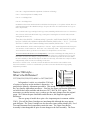
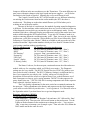
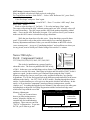
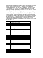
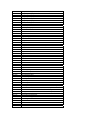
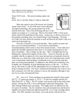
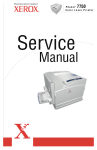
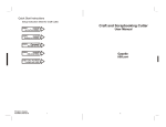
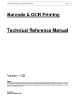
Know When to Run…
(Xerox® 5340 style copiers)
5337,5340,5343,5350,5352,5437,5441,5665,5837,5845,5855
When is it relatively safe to approach a Xerox 5340 style copier
and when should you turn tail and run?
Here is an extremely abbreviated list of the basics of what the status codes mean:
STATUS CODES:
00- Codes
Software problems
01- Codes
Power related problems
02- Codes
Key Counter / Accessory problems
03- Codes
Communication Errors
04-300 Code
Main Motor Failure
05- Codes
Document Feeder Problems
06- Codes
Optics or Exposure Problems
07- Codes
Paper Supply, HCF (High Capacity Feeder) & Interlock
Problems
08- Codes
Paper Feed & Registration Problems
09-300 Code
Copy Cartridge End of Life
09-310 Code
Toner Cartridge (Black) Empty
09-320 Code
Low Color Toner
09-330 Code
Improper Copy Cartridge (fuse failed to blow)
09-340 Code
Copy Cartridge not present (or connector interlock failure)
09-350 Code
Waste Toner Reservoir Full (Need to install a new Copy Cartidge or recondition the
Copy Cartridge w/ a new connector)
other 09 Codes Other Xerographic problems (Bias, Toner Dispense, etc, etc.)
10- Codes
Fuser Codes
10-320 Code
Fuser Web Count Expired (need a new web & reset count
from diagnostics , our webs come with an information sheet)
11- Codes
Sorter / Finisher Problems
The codes you might approach without fear would be the 09-350 code (waste container full) and
perhaps the 10-320 for the Web count being expired.
For the 09-350 code, you’ll need only to replace the Copy Cartridge (which has the waste sump in
it) or clean out the waste sump and replace the Connector on the rear of the Copy Cartridge. The connector
has a fuse on it which must be in place and must blow on power up for the code to clear… We’ve
discovered that a 1/64th amp fuse will serve although sometimes you need to turn the machine off and back
on a couple of times before the fuse blows successfully. The waste container full actuator is a plastic piece
on a float inside the cartridge which rises up into a plastic window on top of the cartridge. When it rises up
it interrupts a photosensor… It’s important that the sensor is clean and also the inside and outside of the
clear plastic window. In this cartridge, the replacement drums are available when needed although often
the drum is still in handsome shape after one cycle.
For the web replacement, you’ll need to be able to get into diagnostics which can be an adventure
in of itself… Here’s how it goes:
ENTERING DIAGNOSTICS… To enter diagnostics in the ‘Un-initialized state’ (necessary if a status
code is currently displayed): Hold ‘Job Interrupt’ button & ‘5’ while turning on the power. Then enter a 4
digit “Access Code” (default code = 8765). You will not see the code displayed as you enter it. If the
default code does not work, and you can’t find the new code written in the machine’s log book (some techs
write it on the inside cover of one of the Owner’s Manuals), you’ll have to use the back door. Find out the
current ‘Total copy count’ (Press the ‘Review’ Button on the console, then press ‘Billing Meters’ on the
touchscreen to show the copy counts). Use the last 4 digits of the total copy count backwards as the
“Access Code”. If the machine is currently in a status code, you will need to press ‘Stop’ twice to clear the
status code screen & bring up the diagnostic screen.
NOTE: In these machines, when in diagnostic mode, Always record very carefully every change you
make… very easy to screw things up in there.
The web reset procedure involves resetting an “HFSI” (High frequency service item”) and also
resetting the counter in the DC Routines. Enter diagnostics and then follow this procedure.
First Enter the HFSI File:(press the HFSI button on the touchscreen) Press the ‘Ovr. Thres.’ button to
bring up a list of HFSI’s which are over the threshold. Use the arrows to scroll down to the web count.
Press the ‘Reset Item’ button, followed by the ‘Print’ button (to lock it in). If you make a mistake, press the
‘Stop’ button to restore a changed value.
Enter the DC Routine File:(press the ‘DC Routine’ button) Enter ‘131’ followed by ‘Print’. Press the
‘M/C Set’ button on the Touchscreen. Scroll down to Line 28 (Fuser Web Total cc). Press ‘Reset File’
button followed by ‘Print’ to confirm the reset.
Choose “Call Close” and use the Quick close option to get out… otherwise your changes will not be saved.
Aside from these two fixes, changing developer, replacing worn parts or doing general cleaning…
if you don’t have the Manual, it’s time to run.
Xerox5340 style... Revisited
(Xerox 5337, 5340, 5343, 5350, 5352)
By Britt Horvat
We originally took a cursory look at the 5340 style of machines in a July 2001 article titled
“Know when to Run”. You can find a copy of that article on ENX’s website
(www.enxmag.com)… go to the “Contributing Authors” link and then scroll down to the stuff
I’ve written (Britt Horvat) where you’ll find a listing of past articles including that one. At
any rate, that article covered the Status Codes as well as how to approach a few of the most
common codes (particularly the codes 10-320 “Web count end of life” and 09-350 “Waste
container full”). Also, as the title suggests, there was a warning that these machines are very
complex and there are some problems you may want to walk away from unless you’re armed
with the full Service Manual. The learning curve however, is near maturity on these and there
are fewer problems, which warrant running away from.
There have also been a few new models (5837, 5845, 5855) added to this line which are quite
different in some ways from the original group (5337, 5340, 5350, 5352). We’ll address the
changes in the new models in a future article.
This month, we’ll revisit this series with some new information goodies we’ve learned along the way.
We’ll also delve into the diagnostics to see how memory adjustments are accessed and what to watch
out for.
Entering Diagnostic Mode: Let’s first go over how to get into the diagnostic mode because that is truly
half of the battle on this series. Here’s how it goes. To enter diagnostics in the ‘Un-initialized state’
(necessary if a status code is currently displayed): Hold ‘Job Interrupt’ button & ‘5’ while turning on
the power. As soon as the machine starts to wake up, enter a 4 digit “Access Code” (the default code =
8765). The machine will not prompt you for the access code, you’ll be entering it blind (you will not
see the code displayed as you enter it). If you’re sure the default code does not work, and you can’t find
the new code written in the machine’s log book (some techs write it on the inside cover of one of the
Owner’s Manuals), you’ll have to use the back door. Find out the current ‘Total copy count’ (Press the
‘Review’ Button on the console, then press ‘Billing Meters’ on the touchscreen to show the copy
counts). Use the last 4 digits of the total copy count backwards as the “Access Code”. If the machine is
currently in a status code, you will need to press ‘Stop’ twice to clear the status code screen & bring up
the diagnostic screen.
If you ever get a call about “no power” or worse, you’ve been working on the machine and all of the
sudden the power doesn’t come up, here’s something you’ll want to know. There is a second On / Off
switch down low on the back of the machine close to where the power cord goes into the machine. It is
easily kicked if you’re moving the machine around and it’s also easily overlooked.
The status code 03-340 has turned out to be a rather common ailment these days. The code means that
the machine detected an abnormal voltage reading from the NVM battery (Non Volatile Memory). In
these machines the IOT NVM chip has the battery built right into the chip. The chip is located on the
IOT board on the rear of the machine (the board is shaped like a large horseshoe). The NVM chip is the
one to the right out of the two eproms you’ll find there. If the machine has been unplugged for an
extended period of time, you'll want to plug the machine in and leave it for a good 24 hours to make
sure the battery has time to recharge, then try powering down and back up. If the code comes back,
resetting the memory could possibly cure it although you may need to pick up a new IOT NVM chip.
In either case, you’ll want to go in and read the existing memory settings before resetting anything. The
settings are all found in “DC131”.
DC131 is accessed from diagnostics mode. You’ll enter diagnostic mode, then press the tab on the
Touchscreen which says “DC Routines”. Then enter the number ‘131’ followed by ‘Print’. From
DC131, you can view and adjust memory settings. Watch your step! Herein lies one of the easiest
pitfalls to stumble into. When in DC131, DO NOT press the button which says ‘Reset File’ nor the one
which says ‘Reset All’. Pressing ‘Reset File’ will return whichever “file” you are currently in, to the
default settings (the memory is divided into 3 “files”, the ‘Engineer’ settings, the ‘Machine’ settings,
and the ‘Auditron’ settings). ‘Reset All’ will return the entire memory to the default settings. Not a
good thing to do, especially because the machine’s defaults are set up for the European markets. If you
ever run across a machine that seems confused about which size paper it has in its drawers, it’s possible
that someone reset the logic in this way. The machine will think it has “A4” paper in tray 1 for
example. To correct this, first search for the machine’s logbook that would have the proper settings
documented. It is a very good idea to write up a log for any machine in your care, so that you’ll have
all of these settings recorded if you ever need them. There are six lines in the “Machine Settings” file
which are particularly important when you are recovering from a memory reset because they are the
ones which pertain to European vs. US settings.
Here they are:
Line 4: HCF Paper Size… default = ‘0’ (for A4 paper), change it to ‘1’ (for 8.5x11 paper)
Line 9: Voltage Setting… default = ‘0’ (for 220 volt), change it to ‘1’ (for 110 volt)
Line 11: Market Setting… default = ‘0’ (for Europe), change it to ‘1’ (for US)
Line 23: Platen Size SEF… default = ‘0’ (for A4), change it to ‘3’ (for 8.5x14)
Line 24: Platen Size LEF… default = ‘0’ (for A4), change it to ‘1’ (for 8x5x11)
Line 25: Platen Size Large… default = ‘0’ (for A3), change it to ‘1’ (for 11x17)
From the DC131 screen, there are 3 buttons on the right side which correspond to the 3 files. The first
is the ‘Eng. ADJ’ button (brings you to the beginning of the “Engineer Adjustments” file), the second is
the ‘M/C Set’ button (brings you to the “Machine Settings” file), the third is the Audit’ button (brings
you to the “Auditron” settings file).
To change a line in any of the three DC131 files, first select that line and then press ‘New Val’. Then
enter the new number you want, followed by ‘Print’ and ‘Print’ again to confirm when you’re
prompted.
Important DC131 Engineer Adjustments:
Line 1 = Lead Edge Registration.
Line 2 & 3 = Registration Buckle adjustment (feed motor off timing)
Line 6 = Fuser temperature in standby mode.
Line 39 = Lead Edge Erase
Line 40 = Trail Edge Erase
In addition to the 6 lines mentioned earlier which have the European vs. US options on them, there are
other important lines in the “Machine settings” file (press the ‘M/C Set’ button from DC131 to get to
these). In particular,
Line 5, which is the Copy Cartridge Total Copy Count (something which can be reset to ‘0’ from here).
Also, Line 28, which is the Web Total Copy Count (part of resetting the 10-320 web-code, includes
setting this line back to ‘0’).
Then there’s the third file, “Auditron settings” (press the ‘Audit’ button from DC131) which
has Line 8 which is the Auditron Administrator Number (default value = ‘11111’. You’ll also
find Line 11 which is the Customer Settings access number (default value = ‘1111’).
Another DC Routine, which is rather important, is ‘DC120’. Again, enter Diagnostic mode, then press
‘DC Routines’ on the touchscreen. Then enter ‘120’, followed by ‘Print’. This is the Fault Log File.
You’ll need to be able to get in here to reset Fuser Over Temperature (10-310) codes.
To reset a 10-310 code (Fuser Over Temperature): Go to line 5 and change the setting back to ‘0’
(it’ll show a ‘1’ if the machine is in the 10-310 status code). Keep an eye on things once you’ve reset
this code to see if the fuser lamp is cycling on and off as it should It is possible for the Fuser SSR to
latch on constantly so that the heat lamp never shuts off. Obviously, that could cause a major overheat
and potentially result in some serious damage to the fuser.
Next time we visit this series, we’ll take a look at the difference between the 5340’s and the newer
5837/45/55 machines. I believe it would benefit you to have some more details about Copy Quality
Adjustment procedures.
Xerox 5340 style…
What’s the Difference?
5337,5340,5343,5350,5352, &5665 vs. 5837,5845,5855
In September’s article, we revisted the 5340 style
of copiers to brush up on the machine’s diagnostics… in
particular the Memory Adjustment procedures. This month, we’ll spend a little time on
the Copy Quality Adjustment procedures… But first. lets figure out what the differences
are between the earlier machines and the newer 5837, 5845, & 5855 copiers. The
newcomers are similar in many ways, yet there are also many changes from the original
group. We’ll hit on the parts similarities and differences, the diagnostic approach
differences.
The new group of models have quite a few important parts in common with the
5340’s. First off, the Drum Cartridges are interchangeable although they may appear
quite different. The Toner Cartridges are also the same (same reorder number too). Feed
Tires and Document Feed components remain the same. The Upper Fuser Roller
Assembly is interchangeable in spite of some changes to the fuser assembly. The Fuser
Lamps are different in the new machines as are the Thermistors. The main differences in
parts came with major changes to the logic boards and power supplies… you’ll find no
similarities in the boards to speak of. Naturally the covers are different as well.
The Control Consoles for the 5837 & 5845 models are very different in that they
are missing the Touchscreens found on the earlier models (the 5855 does have a
touchscreen). This brings us to the other main difference you’ll find when you’re
working on one of the new models…
Because of the lack of a touchscreen, the method of getting around in diagnostics
is different. For the machines with a touchscreen, there are a series of tabs across the top
of the diagnostic screen which you can touch to get to each diagnostic mode. For the
machines which have a Message Display (no touchscreen), most of the modes have been
made available through the DC Routines Mode. To get into ‘DC Routines’ mode is as
simple as entering diagnostics and then pressing ‘print’. Then, just as is the case with the
touchscreens, you’d have to enter the 3 digit routine you’d like to use followed by ‘Print’.
Following is a list of the other “Modes” which are available as tabs across the top of the
touchscreen and the 3 digit routine numbers which you’d use from DC Routines when
you’re using a machine without a touchscreen.
Tab (for touchscreens)
DC Routine # (for non-touchscreens)
“Service Info”
DC103 (enter DC Routines, enter ‘103’, ‘Print’)
“HFSI”
DC135 (enter DC Routines, enter ‘135’, ‘Print’)
“DC Routines”
just press ‘Print’ as mentioned above.
“System Op”
DC150 (enter DC Routines, enter ‘150’, ‘Print’)
“Call Close”
DC188 (enter DC Routines, enter ‘188’, ‘Print’)
“Last 40” (faults)
DC122 (enter DC Routines, enter ‘122’, ‘Print’)
“F. History (faults)
DC125 (enter DC Routines, enter ‘125’, ‘Print’)
The Status Codes are, for the most part, consistent between the older and newer
models with very few exceptions which you’ll likely never notice. The Diagnostic
settings are also very similar. The DC120 “Special Services NVM” file (used to reset
fuser codes & such) is identical. The DC131 (Memory Settings), are different line by
line if you compare the two side by side. Luckily, when you’re in this file, the
description of what each line refers to is right in front of you, so the differences are of
little consequence as long as you’re paying attention. The DC330 codes appear to be
pretty darned close too… (DC330 is the file for testing components such as the exposure
lamp, solenoids, clutches, motors, etc.).
The Copy Quality adjustments for the entire series have remained consistent for
the most part… these adjustments to the density and exposure are the final component
you’d need to work effectively on this series… so let’s get into it. You’ll need to refer to
the September article if you don’t know how to get into diagnostic mode.
Exposure Adjustment (DC601):
For machines with a Touchscreen:
Enter diagnostics… press the “DC Routines” tab and enter ‘601’ followed by ‘Start’
(to get into DC601). Then press the 100% mode button on the touchscreen. Use the
Lighter or Darker buttons on the touchscreen to change the value… You can press
‘Stop’ at any time to interrupt a set of sample copies. Then select the 50% & then the
200% modes and do the same for each.
For machines with a Message Display (no Touchscreen):
Enter diagnostics… press the ‘Start’ button to enter the “DC Routines” menu. Then
enter the number ‘601’ followed by ‘Start’ (gets you into DC601). Follow the
instructions on the Message Display (it’ll walk you through 100%, 200%, and 50%
modes). You can press ‘Stop’ at any time to interrupt a set of sample copies.
The coarse adjustment which will effect all 3 modes at once (100%, 200%, and 50%) is
controlled by a VR (variable resistor). On the 5337/40/43/50/52, use VR67 (found on the
LLM board, located behind the horse-shoe shaped IOT board on the rear of the machine)
or… for the 5837/45/55, use VR257 (found near the upper left corner of the Main
Control Board which is on the rear of the machine). In either case, turning the VR
clockwise will lighten the copy, counterclockwise will darken things up.
Density, ACDC / Bias Calibration, & ADC Setup (DC907):
To get into DC907:
For machines with a Touchscreen (GUI – Graphic User Interface):
Enter diagnostics… press the “DC Routines” tab and enter the number ‘907’ followed
by ‘Start’.
For machines with a Message Display only (TUI – Textual User Interface):
Enter diagnostics… press the ‘Start’ button to enter the “DC Routines” menu. Then
enter the number
‘907’ followed by ‘Start’.
Density Adjustments: (only necessary if the copy appears over or under toned)
• To Tone-up… (The toner motor will pulse and the main and developer drives will
run for 35 seconds).
For Touchscreen machines: from DC907… Select “Tone-up” and press ‘Start’.
Select black or color developer and press ‘Start’ again.
For Message Display machines: from DC907… Enter a ‘3’ to select “Tone up” and
press ‘Start’. Select black or color developer (‘2’ for black, ‘1’ for color) and press
‘Start’. Then ‘Start’ again.
• To Tone-down… (This routine will run 20 copies using a pattern imbedded in it’s
software which uses the ISIL array (Inter & Side Image Lamps) to erase areas).
For Touchscreen machines: from DC907… Select “Tone-down” press ‘Start’. Raise
the Platen Cover (or ADF) with no originals on the glass and select black or color
developer and press ‘Start’ again.
For Message Display machines: from DC907… Enter a ‘4’ to select “Tone down”
and press ‘Start’. Select black or color developer (‘2’ for black, ‘1’ for color) and
press ‘Start’. Then ‘Start’ again.
ACDC/Bias Calibration Adjustment: (Auto Exposure Sensor calibration)
Cover the entire platen glass with 5 layers of good clean white paper (this routine will
scan & update the calibration values).
For Touchscreen machines: from DC907… Select “ACDC/Bias Cal.”. Press ‘Start’ to
start the routine.
For Message Display machines: from DC907… Press ‘1’ to select “ACDC/Bias Cal.”,
then press ‘Start’.
Select black or color developer (‘2’ for black, ‘1’ for color) and press ‘Start’ to begin
the routine.
ADC Setup: (Automatic Density Control)
Place an original with relatively little text on it on the glass.
For Touchscreen machines: from DC907… Select “ADC Reference Set”, press ‘Start’,
select “Black or
Color Developer” and press ‘Start’ again.
For Message Display machines: from DC907… Press ‘2’ to select “ADC setup”, then
press ‘Start’. Select
black or color developer (‘2’ for black, ‘1’ for color) and press ‘Start’ again.
The copier will perform the ADC calibrate routine and a new ADC reference value will
be stored in memory. The ADC target and the ADC Read numbers should be within 5
units… if not, run the ADC Reference Set again. If it is still too far off, you’ll want to
make sure the ADC sensor is clean before trying a third time.
Well, that just about does it for this series. I hope that helps you tackle them
good! If you need to refer to the earlier articles which cover entering diagnostics,
memory adjustments and Status Codes, you can still find them on the ENX website
(www.enxmag.com)… just go to “Contributing Authors” and scroll down to where you
see my picture, next to which you’ll find a listing of the articles I’ve written.
Xerox 5340 style…
Part 4: Component Control
5337,5340,5343,5350,5352, 5665, 5837,5845,5855
This is the 4th installation in a group of articles
about this series. The first was published in ENX in July
of 2001. In that one, you can find things such as Status Codes, how get into diagnostics,
and how to reset the web count. Much later in October and November of 2003, we hit it
again so to speak. In those articles you’ll find stuff about using the Non Volatile
Memory settings files, how to reset Fuser codes, and details about the Copy Quality
Adjustments. You’ll also find a good look at the differences and similarities in the newer
additions to the family… the 5837, 5845, & 5855 models. Reading through these three
articles, I realize that there are a few pieces to the puzzle which are still missing. In this
article, we’ll get into the Component Control procedures (testing motors, sensors,
clutches, etc.). In reading through the Service Manual, I also ran across a few other gems
including how to adjust the Lead Edge Registration and the lead and trail edge erase
which aren’t kept with the rest of the
Diagnostics
‘INITIALISED’
XBB40
Memory Adjustments.
DC330 Component Control - Enter chain #. Counts 1
First, you’ll want to know
Enter Component
Code Name
State
how to go about testing sensors,
Control Code:
Chain Function
motors, solenoids, clutches etc…
essential info for troubleshooting
problems. These tests are run from
Return
“DC330” in Diagnostics. To get into
Press Start to confirm
DC330, you’ll want to go into
Example of the DC330 Diagnostic Screen…
Diagnostic Mode (read about that in the July 2001 article and again in the October 2003
article). The press the button which says “DC Routines” (if the machine has no
Touchscreen, simply press ‘Start’ once you’re in diagnostics). Then enter the number
‘330’ followed by ‘Print’. The “DC330 Component Control” screen will come up.
You’ll need to enter the “Chain”which is the first part of the code, then ‘Print’, followed
by the “Function” code and then ‘Print’ again.
For the Component Codes, you don’t have the same advantage you had when
using the Memory Adjustments. In the NVM (Non Volatile Memory) adjustments files,
you had a scrolling list so you could find what you need. Here, you need to know the
code you want to use. So, it’s necessary to have a list handy of which codes do what.
The list in the Service Manual is rather extensive, so I’ll have to narrow it down a bit for
the sake of this article. I’ve left off stuff like Paper size sensors and most of the Sorter
components as they are too numerous to include. Following is a list of the more
commonly needed Component Codes to use in DC330 (it’s a long list, so I’ll see you on
the other side of it…):
02-100
04-300
05-005
05-010
05-020
05-045
05-100
05-110
05-305
05-312
05-330
05-337
05-339
05-341
06-005
06-010
06-305
06-330
06-357
07-005
07-010
07-017
07-020
07-020
07-025
07-030
07-035
07-040
07-045
07-050
07-055
07-060
07-300
07-310
Tests control console hard buttons… (increments on screen each
time you press one of the buttons).
Main Motor and Output Motor.
Doc Feeder Input Drive Motor (ADF feed rolls)
Doc Feeder Output Drive Motor
Dolc Feeder Entrance Gate Solenoid
Document Present LED
Document Registration Sensor
Document Exit Sensor
Document Drive Motor
Document Present Sensor
Document Nudger Home Sensor (high = home position)
Left Document Cover Interlock Switch (Front)
Left Document Cover Interlock Switch (Rear)
Doc Feeder Platen Interlock Switch
Exposure Lamp
Optics Cooling Fan
Exposure Carriage Registration Sensor
Lens Home Sensor
Auto Exposure Sensor (Hexidecimal reading)
Tray 1 Lift Motor
Tray 1 Nudger Solenoid
Tray 2 Elevate (for newer half moon tires version of Tray 2)
Tray 2 Nudger Solenoid (for newer version of Tray 2)
Tray 2 Feed Clutch (for newer version of Tray 2)
Tray 3 Elevate (for newer version of Tray 3)
Tray 3 Nudger Solenoid (for newer version of Tray 3)
Tray 4 Elevator Motor
Tray 4 Nudger Solenoid
HCF Elevate Up
HCF Nudger Solenoid
Duplex Nudger Solenoid
Duplex Paddlw Wheel Solenoid
Tray 1 Stack Height Sensor
Tray 1 Paper Empty Sensor
07-315
07-325
07-330
07-340
07-345
07-355
07-360
07-363
07-364
07-366
07-368
07-370
07-372
07-375
07-385
08-005
08-010
08-020
08-025
08-030
08-040
08-045
08-060
08-065
08-070
08-090
08-100
08-110
08-120
08-125
08-130
08-135
08-150
09-010
09-015
09-020
09-022
09-030
09-040
09-045
09-050
09-060
09-061
09-062
09-063
09-310
09-315
09-320
09-340
09-350
09-360
10-005
10-007
Tray 2 Stack Height Sensor (for older version of Tray 2)
Tray 2 Paper Empty Sensor
Tray 3 Stack Height Sensor (for older version of Tray 3)
Tray 3 Paper Empty Sensor
Tray 4 Stack Height Sensor
Tray 4 Paper Empty Sensor
HCF Stack Height Sensor
HCF Tray Nudger Sensor
HCF Tray Down Sensor
HCF Paper Empty Sensor
HCF Interlock (HCF to machine interlock)
HCF Door Interlock
HCF Present Sensor
Duplex Tray Interlock
Bypass Empty Sensor
Feed Motor 1
Tray 1 Feed Clutch
Feed Motor 2/3
Tray 2 Feed Clutch (for older version of Tray 2)
Tray 3 Feed Clutch (for older version of Tray 3)
Feed Motor 4
HCF Feed Clutch
Duplex Motor
Duplex Feed Clutch
Registration Gate Solenoid
Bypass Feed Clutch
Feed Sensor 1
Feed Sensor 2
Feed Sensor 3
Feed Sensor 4
HCF Feed Sensor
Duplex Feed Sensor
Lead Edge Registration Sensor
Black Developer Solenoid
Color Developer Solenoid
Pre Transfer Lamps
Erase Lamps
Developer Suction Motor
Black Dispense Motor
Color Dispense Motor
ADC LED on
Developer Bias (Main Motor also comes on if Drum is in place)
Detack Corotron (Main Motor also if Drum is in place)
Transfer Corotron (Main Motor also if Drum is in place)
Charge Scorotron (Main Motor also if Drum is in place)
Black Toner Empty Sensor
Toner Box Present Sensor
Color Toner Empty Sensor
Drum Ctg. Present Sensor
Toner Reclaim Full Sensor
ADC Sensor
Rear Fuser Fan
Front Fuser Fan
10-020
10-100
10-300
10-315
11-300
11-310
Fuser Web Motor
Fuser Exit Sensor
Fuser Temperature Sensor (higher value = cooler fuser)
Fuser Overheat Sensor (higher value = cooler fuser)
Sorter Present Sensor
Sorter Interlock Sensor
Ok, so a list like that does make for some rather dry reading… it is nevertheless
an important bit of info to have around. Again, there were quite a few codes which I
chose to skip over. There are a bunch of notes in the table of codes which refer to the
“older and newer versions of Tray 2 and Tray 3”. This is because some of the machines
were outfitted with different feed heads for Tray 2
and Tray 3 which were designed to be easier to
Tray 2 and 3 tires for machines without Tag 21
(older version) and with Tag 21 (newer version)
service. They called it “Tag 21”… those are the
ones with the half moon tires which are the same
Older Version
Newer Version
as the 5318 series (and also the XC23 series as a
matter of fact). The older version were round
tires which match the Tray 1 and 4 tires. You’ll
(3 pairs of tires on hubs)
(4 half-moon tires)
not find the half moon tires in any of the
5837/5845/5855 or 5665 models.
Another missing piece of info is the way to adjust the Registration and also the
Lead and Trail Edge Erase. These adjustments are accessed using DC Routines, DC604.
The screen which comes up is pretty self explanatory. It shows the “Lead Edge
Registration”, Lead Edge Erase”, and “Trail Edge Erase” with an opportunity to Adjust
the Value (a button on the touchscreen which says “Adj val”) next to each. The range is
from 0 to 42 (default 21) for the Lead Edge Registration. The range for Lead Edge Erase
is 0 to 10… for Trail Edge Erase, the range is 0-16.
I think that just about rounds out this series. Between the 4 articles, you’ve got a
pretty complete picture. If you want to find the older articles, you can go onto ENX’s
website (www.enxmag.com)…. Go to “Contributing Authors” and scroll down till you see
my mug… there you’ll find a list of articles from the past 3 years or so.
Britt works for The Parts Drop, a company who’s purpose is to make available parts,
supplies and information for Xerox brand copiers (as well as some Xerox printers and fax
machines). Expanded Technical Information on some of the models can be found on
their website www.partsdrop.com.