1
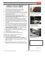
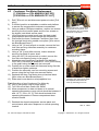
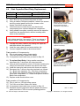
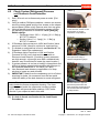
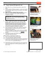
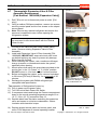
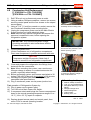
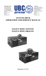
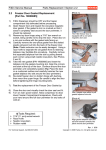
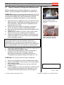
F3Dn Service Manual
4.1
Refrigeration / Section 4.1
Basic [Operator] Refrigeration Maintenance
[Photo 1]
[Before attempting service failure diagnosis or component
repairs, verify basic operator maintenance has been done.]
PROBLEM: Freezer is running but will not reach 0° F [-18° C]
or lower. High temperatures caused by a dirty condenser coil
or extreme ice buildup may cause the freezer to function
improperly, not maintain temperature or cease operating.
1)
2)
3)
4)
5)
Open the freezer compartment door and verify that it has
been defrosted. If significant ice buildup is present, turn
OFF main power, open the freezer compartment door
and allow the ice to melt.
Check freezer door gasket for damage. If damage is
found, see Section 2.2 Door Gasket Replacement.
Remove the top-right side louvered access panel. [Lift up
and pull out.]
Inspect the Condenser Coil Filter. If dirty, wash in sink.
Allow the filter to dry completely before replacing.
Inspect the condenser coil to ensure it is clean and free
of dust and debris. If it is dirty, clean it with a soft bristle
brush or portable vacuum.
To inspect condenser coil and
coil filter, remove louvered
access panel on right side near
unit top.
[Photo 2]
Inspect the condenser coil filter.
If dirty, wash in the sink and
allow to dry before replacing.
CAUTION
Avoid contact with fins on the condenser coil and any
refrigeration lines. The fins are very sharp and can cause
cuts. Certain refrigerant lines can be very hot and could cause
burns to exposed skin. The use of gloves is recommended.
6)
7)
Test unit for operation within 0° to -10° F or -18 to -23° C
normal operating temperature range.
If these steps correct problem, notify unit manager of
problems noted with crew cleaning or operator
preventative maintenance. If problem persists, see
Troubleshooting Guide and Sections 3.8 and 4.2 - 4.9.
PROBLEM: The Freezer will not run when turned ON.
1)
2)
3)
4)
Verify unit is plugged in to correct voltage power supply.
Check circuit breaker for that outlet or use a test meter to
verify power at outlet.
If these simple steps return unit to service, notify unit
manager of fix.
If unit is plugged in, turned on and power is present at the
outlet but Refrigeration System will not power-up, see
Troubleshooting Guide and Sections 4.4 through 4.9.
For Technical Support, Call 800-537-2653.
Ø
Rev. 2 11/06
Copyright Ó 2006 Franke, Inc. All rights reserved.
F3Dn Service Manual
4.2
Refrigeration / Section 4.2
Freezer Thermostat Controller Replacement
[120V/60Hz use Part No. 19000652]
[230V/50Hz use Part No. 19000853]
F3Dn Dispenser should be OFF and the freezer
compartment fully defrosted before proceeding.
2) Disconnect power at outlet. [Pull plug.]
3) Using a medium Phillips screwdriver, remove two screws
from top of front control panel and four screws securing
the sloped access panel.
4) The Danfoss Controller is mounted to the side of an
electric chase, has a knob graduated 1-9; three
connected wires and two cable assemblies. Remove the
press fit knob from the controller.
5) Using a small pliers or adjustable wrench, remove the
hex nut holding controller to the side of metal chase.
6) Disconnect the two cable assemblies from the controller.
Label then disconnect the three wires from the controller
terminals.
7) Place new controller near chase and reconnect the three
wires to the ¼” [6 mm] spade terminals, per your labels.
8) Reconnect cable assemblies from: the LED Display and
the remote sensor. [Connectors are different and can
only be assembled one way.]
9) Position new controller inside electric chase and tighten
hex nut securely…but DO NOT over-tighten.
10) Using the screws previously removed, re-install electric
chase cover.
11) Replace press fit controller knob.
12) Verify the new thermostat is set between 4-5.
[Photo 1]
1)
Test Operation of new thermostat controller by:
13) Plug in unit to power source.
14) Turn ON unit at Main Power-ON Switch.
15) Allow compressor to draw unit down to its normal
operating temperature range, which should be between 0
and -10° F [-18 to -23° C]. [Cool down time of 1-1/2 to 2
hours is normal.]
Remove two screws from front
control panel & four screws that
secure sloped access panel.
[Photo 2]
Remove press fit knob, hex
mounting nut, two cable
harnesses & three wire
connectors to pull thermostat.
[Photo 3]
Unit ships from factory with
thermostat preset at 5. [Dial
range is from 1 to 9.]
Ø
16) Close [black] sloped service access and front control
panels and return dispenser to normal operating location.
Rev. 2 11/06
For Technical Support, Call 800-537-2653.
Copyright Ó 2006 Franke, Inc. All rights reserved.
F3Dn Service Manual
4.3
1)
2)
3)
4)
5)
6)
7)
8)
9)
10)
11)
12)
13)
Refrigeration / Section 4.3
[Photo 1]
Condenser Fan Motor Replacement
[115V/60Hz use P/N: M40045-CA27-E8]
[230V/50Hz use P/N: M4Q045-CF13-A7]
Roll F3Dn unit out and disconnect power at outlet. [Pull
plug.]
If needed, position a stepladder or stable work platform
to access the compressor/condenser compartment.
Using a medium Phillips screwdriver, remove two screws
securing the front control panel and the four screws on
the sloped, matt black access panel.
Lift off and remove metal cover over the black metal
relay/capacitor box mounted behind the compressor.
Disconnect the three Condenser Fan Motor wires from
the terminal block using needle nose pliers. [Wire colors
are Blue/Brown/Green.]
Using a 3/8” [10 mm] wrench or socket, remove the four
lock nuts securing motor/fan assembly to condenser
mounting frame.
Using a 1/8” [3 mm] Allen wrench, loosen setscrew
securing fan blade to motor shaft.
Using the 3/8” [10 mm] wrench or socket, remove the
four lock nuts securing motor to fan guard.
Attach the new Condenser Fan Motor P/N: M40045CA27-E8 [115V/60Hz] or M4Q045-CF13-A7 [230V/50Hz]
to fan guard using the four nuts just removed.
Position fan on motor shaft with setscrew facing flat side
of shaft then tighten setscrew.
Position fan assembly over four mounting screws and
secure using the four lock nuts removed earlier.
Reattach the three Fan Motor wires at terminal block.
[Wire colors are Blue/Brown/Green.]
Slide metal cover back on relay/capacitor box.
Test Operation of new Condenser Fan Motor by:
14) Plug in unit power cord to power supply.
15) Turn ON unit at Main Power-ON Switch.
16) Allow compressor to draw unit down to its normal
operating temperature range, which should be between 0
and -10° F [-18 to -23° C]. Unit should maintain that
operating temperature if freezer compartment door
remains closed.
17) Reattach the sloped compressor access panel and
control panel; and return dispenser to normal operating
location.
For Technical Support, Call 800-537-2653.
Remove the front control panel
and sloped access panel. The
relay/capacitor box is mounted
above the compressor.
[Photo 2]
Disconnect Condenser Fan
Motor wires inside the metal
relay/capacitor box.
[Photo 3]
Remove the four fan housing
mounting nuts, remove fan blade
and separate motor from fan
cover by removing four nuts.
Ø
Rev. 2 12/06
Copyright Ó 2006 Franke, Inc. All rights reserved.
F3Dn Service Manual
4.4
3)
4)
[Photo 1]
Start Capacitor/Start Relay Replacement:
For Model:
115/V 60Hz
230V/50Hz
1)
2)
Refrigeration / Section 4.4
Use Capacitor P/N:
Use Relay P/N:
19001085
19001082
19001080 [Kit containing both]
Roll F3Dn unit out to disconnect power at outlet.
Using a medium Phillips screwdriver, remove two screws
securing control panel and the four screws on the
sloped, matt black access panel.
Lift off and remove metal cover over black metal
relay/capacity box mounted behind the compressor.
Using needle nose pliers, carefully remove the capacitor
leads from the terminal block, without touching each
other or the metal box.
Remove two control panel
screws and four screws on the
sloped panel to access
compressor compartment.
[Photo 2]
WARNING
High voltage warning. Use caution. There is a danger of
electrical shock, which can cause injury or even death!
5)
6)
7)
Pull metal cover off electric
component box to access
capacitor and relay.
Unsnap the plastic retainer clip holding the capacitor,
and then remove the capacitor.
Install the new capacitor and snap retainer clip.
Connect capacitor leads to the terminal block.
[Photo 3]
Test operation of Compressor by:
8) Plug in unit power cord to power supply.
9) Turn ON unit at Main Power-ON Switch.
10) If compressor starts and runs, proceed to Step 19.
11) To replace Start Relay: Using needle nose pliers,
disconnect the 7 wires from the relay terminals.
12) Using a small screwdriver remove 2 screws mounting the
relay to the electrical enclosure and remove the relay.
13) Install the new relay and secure with those two screws.
14) Reconnect the 7 wires to the relay terminals, as follows:
T1 = Black from capacitor; T2 = Red from compressor;
T4 = Black from capacitor, White from power cord and
White from compressor; T5 = Black from power cord and
Black from compressor.
15) Replace metal electrical box cover.
Test operation of Compressor by:
16) Plug in unit to a 120-volt power source.
17) Turn ON unit at Main Power-ON Switch.
18) If compressor starts and runs, proceed to Step 19.
19) Reattach sloped compressor access panel and control
panel; and return F3Dn to normal operating position.
For Technical Support, Call 800-537-2653.
Try replacing the capacitor first.
If replacement of the capacitor
does not start the compressor,
replace the start relay.
Ø
Rev. 2 12/06
Copyright Ó 2005 Franke, Inc. All rights reserved.
F3Dn Service Manual
4.5
1)
2)
3)
4)
5)
6)
7)
8)
9)
Refrigeration / Section 4.5
[Photo 1]
Check System [Refrigerant] Pressure
and Electronic Leak Detection
Roll F3Dn unit out to disconnect power at outlet. [Pull
plug.]
Using a medium Phillips screwdriver, remove two screws
securing control panel and the four screws on the sloped
access panel. [Older units]: Remove wire-form top grate.
Using a standard manifold refrigeration gauge, confirm
the following pressures for units with 16 oz. [454 gm]
R404A charge:
Ø Discharge Valve: 230 +/- 10 psig [16 ± 1 Bar] @
80"F/27°C ambient
Ø Suction Valve: 5 +/- 2 psig [.4 ± .1 Bar] @
80"F/27°C ambient
If Discharge Valve pressure is HIGH and Suction Valve
pressure is LOW, check for a kinked or restricted line.
If a kinked or restricted line is found, see Section 4.7 for
Expansion Valve/Filter replacement.
If Discharge Valve Pressure is LOW and Suction
Pressure is LOW, verify leak and location with an
Electronic Leak Detector. [If existing system pressures
are high enough, a thorough scan with a standard leak
detector may be sufficient to locate the exact location.]
If system pressure is too low or leak[s] is intermittent and
difficult to detect, pressurize the system with Nitrogen to
an equalized MAXIMUM of 150 PSIG [10.5 Bar].
Use electronic leak detector or application of a soap
solution to locate any and all leaks.
IMPORTANT: Make sure the condensing unit is off when
checking for leaks. Air movement from the fan would
inhibit the ability of the leak detector to sense refrigerant.
NOTE: Do not use an electronic leak detector to locate
leaks inside the freezer evaporator housing. The foam
insulation used inside the evaporator housing contains
HFCs, which will generate false readings. Call Franke
Service if you suspect a leak in this area.
Remover two control panel
screws and four screws on the
sloped panel, to access
compressor compartment.
[Photo 2]
Check Discharge and Suction
Valve pressures using a
manifold refrigeration gauge.
[Photo 3]
If system pressure is too low or
the leaks difficult to pinpoint,
pressurize system with 150
PSIG [10.5 Bar] of Nitrogen and
use an electronic leak detector
or soap solution.
Ø
10) If a leak is found, see Section 4.6 for Leak Repair
Procedures.
Rev. 2 12/06
For Technical Support, Call 800-537-2653.
Copyright Ó 2005 Franke, Inc. All rights reserved.
F3Dn Service Manual
4.6
1)
2)
3)
4)
Refrigeration / Section 4.6
[Photo 1]
Repair System [Refrigerant] Leak
Roll F3Dn unit out to disconnect power at outlet. [Pull
plug.]
Using a medium Phillips screwdriver, remove two screws
securing control panel and the four screws on the sloped
access panel.
Repair or replace refrigerant lines as needed.
Note: Recover any residual refrigerant and ensure line
pressure is equalized to zero, before opening the
refrigeration system.
[Photo 2]
IMPORTANT: Any residual refrigerant charge
should be recovered in strict accordance with the
Federal Clean Air Act.
5)
6)
7)
8)
Remove two control panel
screws and four screws on the
sloped panel to access
compressor compartment.
Note: For larger leaks that may have contaminated the
system, replace the expansion valve and filter. [See
Section 4.7] In addition, the system may need to be
drained completely and new Polyol Ester Oil added. If
required, the old Polyol Ester Oil should be recovered
and disposed of in accordance with Federal Laws
covering the handling of hazardous materials.
When resealing the system, use a continuous Nitrogen
charge to assure no contaminants enter the system,
especially when brazing.
Before recharging the system, pull a vacuum equivalent
to 30 inches [760 mm] of Mercury, for a minimum of 30
minutes.
Recharge the system with R404A refrigerant, per
nameplate label specification.
Test operation of Refrigeration System by:
9) Plug in unit power cord to power source.
10) Turn ON unit at Main Power-ON Switch.
11) If compressor starts and brings the Freezer compartment
down to the normal operating temperature range of 0 to 10° F [-18 to -23° C], proceed to Step 12.
12) Reassemble sloped access panel and control panel and
return F3Dn dispenser to normal operating location, if it
was moved.
Recover any residual refrigerant
and ensure line pressure is zero
before opening system.
[Photo 3]
When resealing the system or
repairing leaks, use continuous
Nitrogen charge to keep
contaminants out.
Ø
Rev. 2 11/06
For Technical Support, Call 800-537-2653.
Copyright Ó 2006 Franke, Inc. All rights reserved.
F3Dn Service Manual
4.7
1)
2)
3)
Refrigeration / Section 4.7
Thermostatic Expansion Valve & Filter
Assembly Replacement
[Part Number: 19000496 (Expansion Valve)]
Roll F3Dn unit out to disconnect power at outlet. [Pull
plug.]
Using a medium Phillips screwdriver, remove two screws
securing control panel and the four screws on the sloped
access panel.
Note: Recover any residual refrigerant and ensure line
pressure is equalized to zero, before opening the
refrigeration system.
[Photo 1]
Remover control panel screws
and four screws on the sloped
panel to access compressor
compartment.
[Photo 2]
IMPORTANT: Any residual refrigerant charge should
be recovered in strict accordance with the Federal
Clean Air Act.
4)
5)
6)
7)
8)
9)
Cut line to free valve and filter using a small tubing
cutter. Remove existing Expansion Valve & Filter
Assembly.
Install new Expansion Valve & Filter Assembly [P/N:
19000496]. IMPORTANT: wrap valve body with a wet
rag before applying any heat, to prevent any damage.
Braze lines as required.
When resealing the system, use a continuous Nitrogen
charge to assure no contaminants enter the system,
especially when brazing.
Mount sensor bulb using the strap clamp provided to the
suction line, in the “10 o’clock” or “2 o’clock” position.
DO NOT mount in 12 o’clock or 3 to 9 o’clock position.
Before recharging the system, pull a vacuum equivalent
to 30 inches [760 mm] of Mercury, for a minimum of 30
minutes.
Recharge the system with R404A refrigerant per
nameplate label specification.
Test operation of Refrigeration System by:
10) Plug in power cord to power outlet.
11) Turn ON unit at Main Power-ON Switch.
12) If compressor starts and brings the Freezer compartment
down to the normal operating temperature range of 0 to 10° F [-18 to -23° C], proceed to Step 13.
13) Replace black foam insulation enclosing the expansion
valve and sensor to minimize condensation. Secure
insulation with electrician’s tape.
14) Replace sloped access panel and control panel; and
return F3Dn dispenser to normal operating location.
For Technical Support, Call 800-537-2653.
Recover any residual refrigerant
and ensure line pressure is zero
before opening system.
[Photo 3]
When resealing the system, use
a continuous Nitrogen charge to
keep contaminants out.
Ø
Rev. 2 12/06
Copyright Ó 2006 Franke, Inc. All rights reserved.
F3Dn Service Manual
4.8
1)
2)
3)
4)
5)
Refrigeration / Section 4.8
[Photo 1]
Condensing Unit Replacement
[110V/60Hz use P/N: 19000359]
[230V/50Hz use P/N: 19000453]
Roll F3Dn unit out to disconnect power at outlet.
Using a medium Phillips screwdriver, remove two screws
securing control panel and the four screws on the sloped
access panel.
Using a 7/16” [11 mm] box wrench or socket, remove the
two Condenser Assembly base mounting bolts.
Unplug the compressor power cord at the Main Electric
Supply junction box inside electrical chase.
Note: Recover any residual refrigerant and ensure line
pressure is equalized to zero, before opening the
refrigeration system.
Remove the two Condenser
Assembly base mounting bolts.
[Photo 2]
IMPORTANT: Any residual refrigerant charge
should be recovered in strict accordance with the
Federal Clean Air Act.
6)
7)
Cut the refrigerant lines.
Lift old Compressor out of refrigeration compartment.
Place new compressor in position and secure with nuts.
Recover any residual refrigerant
and ensure line pressure is zero
before opening system.
[Photo 3]
CAUTION
Compressor weights 50-pounds. Obtain help if
needed to remove from refrigeration compartment.
8)
Clean and prepare the refrigeration line fittings, then
braise all the line connections.
9) Note: When resealing the system, use a continuous
Nitrogen charge to assure no contaminants enter the
system, especially when brazing.
10) Before recharging system, pull vacuum equivalent to 30
inches [760 mm] of Mercury, for minimum of 30 minutes.
11) Recharge the system with R404A refrigerant, per
nameplate label specifications.
12) Plug in condenser power cord at power junction box.
Test operation of Refrigeration System by:
13) Plug in power cord to power outlet.
14) Turn ON unit at Main Power-ON Switch.
15) If compressor starts and brings the Freezer compartment
down to the normal operating temperature range of 0 to 10° F [-18 to -23° C], repair is complete.
16) Replace sloped access panel and control panel; then
return F3Dn to normal operating location.
For Technical Support, Call 800-537-2653.
When resealing the system, use
a continuous Nitrogen charge to
keep contaminants out.
@Tools/Supplies Required:
Ø Medium Phillips screwdriver
Ø 7/16” [11 mm] socket/wrench
Ø Refrigerant Recovery Tank &
fittings
Ø Nitrogen Charge Tank
Ø R404A Refrigerant
Ø Tubing Cutter
Ø Brazing Torch, etc.
Rev. 2 12/06
Copyright Ó 2006 Franke, Inc. All rights reserved.