1
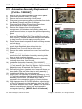
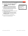
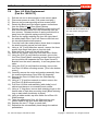
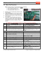
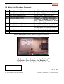
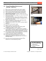
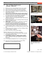
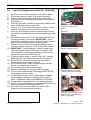
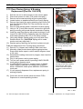
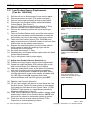
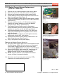
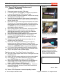
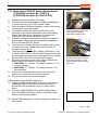
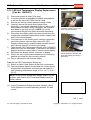
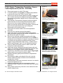
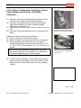
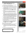
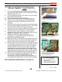
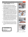
F3Dn Service Manual
2.2
1)
2)
3)
4)
5)
6)
Parts Replacement / Section 2.2
[Photo 1]
Freezer Door Gasket Replacement
[Part No. 19000685]
F3Dn Dispenser should be OFF and the freezer
compartment fully defrosted before proceeding.
Open freezer door and inspect the one-piece magnetic
door gasket. If the gasket is torn or crushed so that it
doesn’t completely seal around the door perimeter, it
should be replaced.
Remove top door hinge using a 7/16” box wrench or
socket, being careful not to drop the door. Place door on
a non-mar surface with the gasket side facing up.
Carefully remove the one-piece gasket from the slotted
plastic extrusion built into the back of the freezer door.
[Note: Plastic extrusion can be easily damaged. Using a
razor knife to separate the old gasket from its retaining
tailpiece may facilitate this procedure. Carefully remove
the separated tailpiece from the slot by pulling toward
each corner using small needle nose pliers. See Photos
2 and 3]
Take the new gasket [P/N 19000685] and insert the
tailpiece into the gasket-mounting slot. Align the corners
and start at the top of the door. Continue around the door
perimeter until completely seated. [Tip: Place the door
on a cushioned surface and carefully hammer the new
gasket tailpiece into slot around the door perimeter.]
Re-install freezer door on bottom hinge with bushing,
then mount the upper hinge. Be careful to align the door
before tightening the hinge mounting bolts.
7)
Test the replacement of the Freezer Door Gasket by:
8)
9)
Close the door and visually check the door seal and fit.
Turn on main power switch. Allow compressor to draw
down Freezer Compartment temperature. Check with
your hand around the full door perimeter for any leaks of
cold air.
The F3Dn freezer door is
equipped with a one-piece
magnetic door seal.
[Photo 2]
To speed replacement, just cut
away the old door gasket from
its tail piece.
[Photo 3]
Use a needle nose pliers to pull
gasket tailpiece from slot.
[Photo 4]
@Tools Required:
Ø
Ø
Ø
Ø
7/16” [11 mm] socket wrench
Razor knife
Needle nose pliers
Rubber mallet
Align gasket tailpiece with door
slot and hammer carefully into
place around door perimeter.
Rev. 1 6/06
For Technical Support, Call 800-537-2653.
Copyright Ó 2006 Franke, Inc. All rights reserved.
F3Dn Service Manual
Parts Replacement / Section 2.3
[Photo 1]
2.3 Automation Assembly Replacement
[Part No. 18000567]
1)
2)
3)
4)
5)
6)
7)
8)
9)
10)
11)
12)
13)
14)
15)
16)
17)
18)
Roll the unit out to allow access to rear service panel.
Disconnect power at outlet. [Pull plug.]
Remove two screws securing service panel.
Disconnect motor harness power connections from both
the Basket [Present] and Door Lift Motors.
Disconnect both Basket [Present] and Door Open
Sensor leads at the Main Control Board.
Remove the Hoppers from the refrigeration
compartment, the stainless steel loading chutes and
plastic freezer bottom, to expose the product dispensing
doors.
Remove [and save] the spring retaining clip from the left
side Door Rotation Block Pin. [Slip round loop over pin
then remove.] Release tension on the spring and allow it
to hang from the right side spring mounting screw.
Rotate doors down to expose the shaft mounting screws
on both doors.
Using a 1/8” [3 mm] Allen/hex wrench, remove the three
screws that attach each door to its pivot shaft.
Slide the Door Frame off the left door shaft.
Remove the rubber seal and hole cover from both Door
Shafts.
Using a 7/16” [11 mm] box wrench or socket/wrench
remove the four Automation Assembly mounting bolts
from the side mounting channels.
Carefully remove the complete Automation Assembly,
including door shafts, from the unit.
Install new Automation Assembly [P/N 18000567].
Replace and tighten the mounting bolts using your 7/16”
[11 mm] wrench. [Tip: Don’t fully tighten. Some mounting
adjustment may be required. See Section 3.1]
Reinstall hole covers, gaskets, door frame and doors on
door shafts. [Tip: See other Lane to verify assembly.]
Install freezer bottom for next adjustment.
Adjust Door Lift Assembly by minimal tightening of 7/16”
[11 mm] bolts and then manually positioning the Door Lift
Assembly front-to-back, so that the door frame is
centered in the rectangular opening of freezer bottom.
With dispense doors in CLOSED position, adjust height
of Door Lift Assembly so that dispense doors just “kiss”
the freezer bottom to form a seal. [Note: Care should be
taken to keep dispense doors level and centered in
rectangular opening.] [MORE…See 2.4 Continued]
For Technical Support, Call 800-537-2653.
Disconnect power leads from
both motors.
[Photo 2]
Disconnect sensor leads at the
Main Control Board.
[Photo 3]
Open load doors from the front
and remove three shaftmounting screws on each.
[Photo 4]
Remove the four Automation
Assembly mounting bolts.
Copyright Ó 2005 Franke, Inc. All rights reserved.
F3Dn Service Manual
Parts Replacement / Section 2.3
Rev. 1 6/06
2.3 Automation Assembly Replacement
Continued: [Part No. 18000567]
@Tools Required:
Ø 3/8” [10 mm] flat blade
screw driver
Ø 1/8” [3 mm] Allen
Wrench
Ø 7/16” [11 mm] box or
socket wrench
19) Tighten all 7/16” [11 mm] bolts securely and recheck
dispense door-to-bottom “kiss” seal for uniform fit.
20) Reattach power service wires to both motors [Red =
positive, black = negative] and sensor leads to Main
Control Board. [See other Lane to verify connections.]
21) Plug in unit power cord to power supply.
22) Test Automation Assembly operation by:
23) Turning on main power switch & pressing LANE-POWER
touch pad on control overlay.
24) If LOAD READY light is on, position empty fry basket
under hopper to activate fry loading cycle, if lane is in
AUTO mode. If in MANUAL mode, press the MANUAL
DISPENSE touch pad.
25) If Lane dispenses fries, it is working properly.
26) Close rear service access panel and return F3Dn
Disperser to normal operating location.
For Technical Support, Call 800-537-2653.
Copyright Ó 2005 Franke, Inc. All rights reserved.
F3Dn Service Manual
2.4
1)
2)
3)
4)
5)
6)
7)
8)
9)
10)
11)
12)
13)
14)
15)
16)
17)
18)
19)
20)
21)
Parts Replacement / Section 2.4
[Photo 1]
Door Lift Slide Replacement
[Part No. 18000673]
Roll the unit out to allow access to rear service panel.
Disconnect power at outlet. [Pull power cord plug.]
Remove two screws securing service access panel.
Detach the Black and Red electric power connections
from the Slide Lift and Door [Open] Motors.
Remove [and save] the spring retaining clip from the left
side Door Rotation Block Pin. Slip round loop over pin
then remove. Release tension on spring and allow it to
hang from the right side spring mounting screw.
Remove the spring retaining clip from the right side of
the white plastic Door Cam Link. Remove that link and
the two small plastic shaft spacers.
From the front side rotate product doors down to expose
the shaft mounting screws on both doors.
Using a 1/8” [3 mm] Allen/hex wrench, remove the three
screws that attach each door to its pivot shaft.
Slide the Door Frame off the left door shaft.
Remove the rubber seal cover from both Door Shafts.
Using the 5/32” [4 mm] Allen/hex wrench, remove the
four Door [Open] Motor mounting screws. Removing the
two top screws will separate the Door Open Sensor &
Bracket from the motor assembly. It can hang down from
cable.
Using the 5/32” [4 mm] Allen/hex wrench, remove the
four Door Lift Motor mounting screws. [This is the bottom
motor.]
Carefully remove the motor and gearbox assembly from
the machined aluminum Door Slide Lift Assembly.
Remove the Door Lift Shaft from the Slide Bearing
Assembly.
Using a ¼” [6 mm] box wrench or socket, remove the
four Door Lift Slide mounting bolts.
Pull Door Lift Slide sub-assembly [with shafts] out of
cabinet and place on a convenient work surface.
Using a ’C’ ring pliers, remove both retaining rings on the
freezer side of each door mounting shaft. [Back retaining
ring on each shaft should stay in place.]
Using a rubber mallet, tap door shafts out of Door Lift
Slide bearings.
Take the replacement Door Lift Slide and use your
rubber mallet to tap door shafts back into place.
Replace the two ‘C’ Rings on each shaft.
Reposition the sub-assembly back though the cabinet
penetrations.
For Technical Support, Call 800-537-2653.
Remove the spring clip retainer
from left side door rotation block
pin, then relieve spring tension.
[Photo 2]
Remove the two upper motor
mounting screws first.
[Photo 3]
Open load doors from the front
and remove three shaftmounting screws on each.
Ø
.
Copyright Ó 2006 Franke, Inc. All rights reserved.
F3Dn Service Manual
Parts Replacement / Section 2.4
2.4
Door Lift Slide Replacement
[Photo 4]
CONTINUED [Part No. 18000673]
22) Align the assembly and reinstall the four mounting bolts.
23) Reinstall hole covers, gaskets, door frame and doors on
door shafts. [Tip: See other Lane to verify assembly.]
24) Install Door [Open] Motor assembly starting with the two
bottom mounting screws. Remount Door Open Sensor &
bracket using the two upper motor mount screws.
25) Reconnect the two motor electric power connections:
[Red = positive; Black = negative].
26) Replace white plastic Door Cam Link, with Stop Screw to
the right side. [Note: Make sure bushings and spacers
are on both left and right cam pins, before replacing link.
27) Attach the spring retainer clip to right side Door Rotation
Block pin.
28) Using both hands, extend spring eye to left side Door
Rotation Block Pin. [CAUTION: Spring will be under
tension and may snap back.] Plastic bushings must be
installed in spring end loops, before mounting the spring.
29) Replace spring retaining clip and lock in place over pin.
30) Reposition the Door Lift Shaft in the Slide bearing
Assembly.
31) Reinstall the Door Lift Motor Assembly [P/N 19000161].
Make sure the gear box output shaft fits into the slot in
the lift cam.
32) Replace and tighten the four motor mounting screws
using your 5/32” [4 mm] Allen wrench.
33) IMPORTANT - Check the gap or calibration of the load
cell [weighs basket contents] under the motor by
inserting a .020” [.50 mm] feeler or gap gauge between
set post on left [open] side of load cell. [See Photo 6]
34) If load cell gap is larger or smaller than .020”/.50 mm,
adjust gap set nut located below left side of load cell.
35) Attach power service wires to Door Lift Motor. [Red =
positive, Black = negative]
Test the replacement Door Slide Lift as follows:
36) Plug in unit power cord to 120-volt power supply.
37) Turn on main power switch & pressing LANE-POWER
touch pad on front control overlay.
38) If LOAD READY light is on, position empty fry basket
under Hopper to activate fry loading cycle. [AUTO Mode]
39) If Lane properly dispenses fries, the Automation
Assembly is working properly.
Remove the four motor mounting
screws from the Door Lift Motor.
[Photo 5]
Ensure motor drive aligns with
the slot in the slide plate counter
bore.
[Photo 6]
After replacing this motor, check
the gap on the load cell using a
.020 [.50 mm] feeler or gap
gauge.
40) Close rear service access panel and return F3D
Dispenser to normal operating location.
Rev. 1 9/06
For Technical Support, Call 800-537-2653.
Copyright Ó 2006 Franke, Inc. All rights reserved.
F3Dn Service Manual
2.5
Motor Test / Section 2.5
Motor Test Procedure
Note: Follow this Motor Test Procedure before replacing:
§ Drum Rotor Motor [Section 2.6]
§ Door Lift Motor [Section 2.7]
§ Door [Open] Motor [Section 2.8
1)
2)
3)
4)
Roll the unit out to allow easy access to rear
service panel.
Leave unit plugged in but be cautions when
opening unit back and touching Boards, etc.
Remove the two screws to open rear service
access panel.
Go to Main Control Boards and locate the
diagnostic display (upper right) and three
white command buttons marked: SW1, SW2
and SW3, just below the display surface
mount.
Key: Bold type = Actual Display Content. // = Break to second line of Display
Action Required
Resulting Diagnostic Display
From unit front turn Lane Power Touch
Display will cycle through setup screens
Pad ON.
ending with: Stby [Standby].
Push and hold buttons: SW1 and SW3:
All Clear?? // 1=OK 3=Exit
2
U.S. or Alt?? // 1=US 2= Alt. [Alternate]
3
Press SW1 button. [=OK]
Press
SW1
or
SW2
button
as
required.
Preload = 2175 [Four digit number]
4
Add Large Load [681 gm or 1.5 lbs.] //
[Procedure assumes SW1=US pressed.]
1=OK
Note: Check to verify fries loading chute is in place and no stray fries are in loading area.
5
Press SW1 button. [=OK]
6
Add 1.5 pound weight [or six 4:1 Patties] to
lane product loading chute.
Large = 226 // Z = ---- P= ---- C=---- //
7
Press SW1 button. [=Cal]
Done 1= Cal 3 = Exit
8
Press S3 button. [to exit Calibration Test]
Press and hold S2 and S3 buttons
Motor Test ? // 1=OK 2= Nxt 3=Exit
9
Drum Mtr? // 1= OK 3=Nxt [Next]
10
Press SW1 button. [=OK]
Drum Trq = 0000 [Torque value] // 1 =
11
Press SW1 button. [=OK]
Run 3 = Next
Drum Trk = 00XX [Numeric value will
12
Press SW1 button to run motor. Check
motor shaft and listen for excessive noise. change. A high number means a problem.]
Lift Motor? // 1 = OK 3 = Next
13
Press SW3 button [=Next Test].
Trq = 0000 LC = 0000 [Load Cell] //
14
Press SW1 button. [=OK]
1 = Run 3 = Next
Trq = 00XX [Typically small value] LC =
15
Press SW1 button. [Lowers slide, turns
XXXX [Live reading from Load Cell. Can
cam & motor rotates.]
check load cell function.]
Step
1
For Technical Support, Call 800-537-2653.
Copyright Ó 2006 Franke, Inc. All rights reserved.
F3Dn Service Manual
Motor Test / Section 2.5
2.5 Motor Test Procedure Continued:
Step
16
17
18
19
20
Action Required
Press SW3 button. [Go to next test.]
Press SW1 button. [=OK]
Press SW1 button. [Activates one full
door-open & dispense cycle.]
Press SW3 button [=Next].
Press SW1 button. [=OK]
21
22
23
Press SW3 button [=Clear]
Press SW3 button [=Rtn]
Press SW1 button [=OK]
24
25
Press SW3 button [=OK]
Press SW3 button [=Exit]
Resulting Diagnostic Display
Door Motor? // 1 = OK 3 = Nxt [Next]
Door Trq = 0000 // 1 = Go 3 = Ex [Exit]
Door Trq = 00XX [Typically a low value] //
1 = Go 3 = Ex XXX [Cycle count]
Error Log ? 1 = OK 2 = Nxt 3 = Ext
FTO=000 [Fill Time Out – the number of
occurrences] DTQ=000 [Drum torque
faults – number of occurrences] // 2 = Clr
3 = Rtn [Return]
Resets FTO and DTQ counters to “000”
Show Cal ? // 1 = OK 2 = Nxt 3 = Ext
Z = 00000 C= 00024 P = 02145 // 1 = OK
3 = Ext [Values should be close to those
on sticker. See photo below.]
Motor Tests ? 1 = OK 2 = Nxt 3 = Ext
Shut Lift /Stby [Standby]
Specific base-level Diagnostic Values are logged at Plant and
posted on back of unit above Main Control Boards.
Ø To Replace Drum Rotor Motor…See Section 2.6
Ø To Replace Door Lift Motor…See Section 2.7
Ø To Replace Door [Open] Motor…See Section 2.8
Ø
Rev. 2 10/06
For Technical Support, Call 800-537-2653.
Copyright Ó 2006 Franke, Inc. All rights reserved.
F3Dn Service Manual
2.6
Parts Replacement / Section 2.6
[Photo 1]
Drum Rotor Motor Replacement
[Part No. 19000161]
1)
2)
3)
4)
5)
Roll unit out to allow access to rear service panel.
Disconnect power at outlet. [Pull power cord plug.]
Remove two screws securing service access panel.
Disconnect both motor harness power connections.
Using a 5/32” [4 mm] Allen Wrench, remove the four
motor mounting screws.
6) Remove motor by pulling straight out. Motor Rotor Block
will remain in place.
7) Install new Drum Rotor Motor [P/N 19000161]. Ensure
motor gear case drive shaft engages rectangular slot in
plastic Rotor Drive Shaft.
8) Replace and tighten the four motor mounting screws
using your 5/32” [4 mm] Allen Wrench.
9) Reattach power leads to motor: [Red = positive, Black =
negative]
10) Reconnect unit to power supply.
11) Test for proper motor operation by:
12) Turning ON main power switch & pressing LANEPOWER touch pad on control overlay.
13) If LOAD READY light is on, position empty fry basket
under hopper to activate loading cycle in AUTO Mode. In
MANUAL Mode press MANUAL DISPENSE touch pad.
14) If Fry Hopper is empty, place screwdriver or knife blade
in front of load sensor to trick the dispenser.
15) Position an empty fry basket in the fill chute.
16) If lane dispenses fries [if present] or if rotors turn
smoothly in an attempt to dispense fries, the motor is
working properly.
Disconnect motor power
leads.
[Photo 2]
Remove the four motor
mounting screws.
17) Close rear service access panel and return F3Dn
Dispenser to normal operating location.
@Tools Required:
Ø 3/8” [10 mm] flat blade
screw driver
Ø 5/32” [4 mm] Allen
Wrench
Rev. 1 9/06
For Technical Support, Call 800-537-2653.
Copyright Ó 2006 Franke, Inc. All rights reserved.
F3Dn Service Manual
2.7
Parts Replacement / Section 2.7
[Photo 1]
Door Lift Motor Replacement
[Part No. 19000161]
1)
2)
3)
4)
Roll the unit out to allow access to rear service panel.
Disconnect power at outlet. [Pull power cord plug.]
Remove two screws securing service access panel.
Disconnect motor harness power connections from the
[lower] Door Lift Motor.
5) Using a 5/32” [4 mm] Allen/hex wrench, remove the four
motor mounting screws. [They are all the same length.]
6) Carefully remove the motor and gearbox assembly from
the machined aluminum Slide Bearing Assembly.
7) Install the new Door Lift Motor Assembly [P/N
19000161]. Make sure the gear box output shaft fits into
the slot in the lift cam.
8) Replace and tighten the four mounting screws using your
5/32” [4 mm] Allen wrench.
9) IMPORTANT - Check the gap or calibration of the load
cell [weighs basket contents] under the motor by
inserting a .020” [.50 mm] feeler or gap gauge between
set post on left [open] side of load cell. [See Photo 3]
10) If load cell gap is larger or smaller than .020” [.50 mm],
carefully adjust gap set nut located below left side of load
cell.
11) Attach power service wires to new Door Lift Motor. [Red
= positive, Black = negative]
12) Plug in unit power cord to power supply.
Disconnect power leads from
[lower] Door Lift Motor.
[Photo 2]
Remove the four motor mounting
screws.
[Photo 3]
Test the replacement Door Lift Motor as follows:
13) Turn on main power switch & pressing LANE-POWER
touch pad on control overlay.
14) If LOAD READY light is on, position empty fry basket
under hopper to activate fry loading cycle in AUTO
Mode. In MANUAL Mode press MANUAL DISPENSE
touch pad.
15) If Lane properly dispenses fries, it is working properly.
16) Close rear service access panel and return F3Dn
Dispenser to normal operating location.
Ø
After replacing motor, check the
gap on the load cell using a
.020”/.50 mm feeler or gap
gauge.
Rev. 1 9/06
For Technical Support, Call 800-537-2653.
Copyright Ó 2006 Franke, Inc. All rights reserved.
F3Dn Service Manual
2.8
1)
2)
3)
4)
5)
6)
7)
8)
9)
10)
11)
12)
13)
14)
15)
Parts Replacement / Section 2.8
[Photo 1]
Door [Open] Motor Replacement
[Part No. 18000558]
Roll the unit out to allow access to rear service panel.
Disconnect power at outlet. [Pull power cord plug.]
Remove two screws securing service access panel.
Remove [and save] the spring retaining clip from the left
side Door Rotation Block Pin. Slip round loop over pin
then remove. Release tension on spring and allow it to
hang from the right side spring mounting screw.
Remove the spring retaining clip from the right side of
the white plastic Door Cam Link. Remove that link. [You
don’t need to remove the small plastic shaft spacers.]
Using the 5/32” [4 mm] Allen/hex wrench, remove the
four motor mounting screws, beginning with the two TOP
screws.
Removing the longer top screws will separate the Door
Open Sensor & Bracket from the motor assembly.
Detach the two motor electric power connections.
Install new motor assembly [P/N 18000558] starting with
the two bottom mounting screws.
Remount Door Open Sensor & bracket using the two
upper motor mount screws.
Reconnect the two motor electric power connections:
[Red = positive; Black = negative].
Replace white plastic Door Cam Link, with Stop Screw to
the right side. [Note: Make sure bushings and spacers
are on both left and right cam pins, before replacing link.]
Attach the spring retainer clip to right side Door Rotation
Block pin.
Using both hands, extend spring eye to left side Door
Rotation Block Pin. [CAUTION: Spring will be under
tension and may snap back.] Plastic bushings must be
installed in spring end loops, before mounting the spring.
Replace spring retaining clip and lock in place over pin.
Test the replacement Door [Open] Motor as follows:
16) Plug in unit power cord to power outlet.
17) Turn on main power switch & pressing LANE-POWER
touch pad on front control overlay.
18) If LOAD READY light is on, position empty fry basket
under Hopper to activate fry loading cycle in AUTO
Mode. In MANUAL Mode press MANUAL DISPENSE.
19) If Lane properly dispenses fries, replacement Motor and
dispensing assembly is working properly.
20) Close rear service access panel and return F3Dn
Dispenser to normal operating location.
For Technical Support, Call 800-537-2653.
Remove the spring clip retainer
from left side door rotation block
pin, then relieve spring tension.
[Photo 2]
Remove the two upper motor
mounting screws first.
[Photo 3]
Ensure motor drive aligns with
the slot in the slide plate counter
bore.
Ø
Rev. 1 9/06
Copyright Ó 2006 Franke, Inc. All rights reserved.
F3Dn Service Manual
2.9
1)
2)
3)
4)
5)
6)
7)
8)
9)
10)
11)
12)
13)
14)
15)
16)
17)
18)
19)
20)
Parts Replacement / Section 2.9
Load Cell Replacement [Part No. 19000165]
Roll the unit out to allow access to rear service panel.
Disconnect power at outlet. [Pull power cord plug.]
Remove two screws securing service access panel.
Disconnect Load Cell cable lead at Main Control Board.
[See Photo 1]
Carefully open split in plastic wire harness sheath to free
cable all the way down to Load Cell.
Using a 3/16” [5 mm] Allen/hex wrench, remove the two
Load Cell bracket screws and remove assembly.
Using a 5 mm Allen/hex wrench separate the Load Cell
from its Mounting Bracket by removing the two right-side
screws.
Re-attach the new Load Cell to the old Bracket with the
mounting screws just removed. IMPORTANT – when
mounted on assembly, there must be clearance between
back of load cell and assembly mounting plate.
Remount the Load Cell Assembly and tighten the two
mounting screws using your 3/16” [5 mm] Allen wrench.
IMPORTANT – After installation, check the gap of the
load cell [weighs basket contents] by inserting a .020”
[.50 mm] feeler or gap gauge between set post on left
[open] side of load cell. [See Photo 4]
If load cell gap is larger or smaller than .020”, carefully
adjust gap set nut located below left side of load cell.
Reroute Load Cell cable lead back up to the Main
Control Board and re-attach terminal.
Re-route and bundle cable in flexible plastic harness
sheath. Use plastic ties, if needed.
Plug in unit power cord to power supply.
Test the replacement of the Load Cell as follows:
Turn on main power switch & pressing LANE-POWER
touch pad on control overlay.
If LOAD READY light is on, position empty fry basket
under hopper to activate fry loading cycle in AUTO
Mode. In MANUAL Mode press MANUAL DISPENSE.
If Lane properly dispenses fries, it is working properly.
[NOTE: It may be necessary to recalibrate load cell using
procedure provided with replacement unit.
Close rear service access panel and return F3Dn
Dispenser to normal operating location.
[Photo 1]
Disconnect Load Cell cable
connector at Main Control
Board.
[Photo 2]
Remove the two Load Cell
Bracket mounting screws.
[Photo 3]
Separate Load Cell from the
mounting bracket by removing
screw on right side of assembly.
[Photo 4]
After replacing Load Cell
Assembly, check the gap on the
load cell using a .020 [.50 mm]
feeler or gap gauge.
Rev. 1 9/06
For Technical Support, Call 800-537-2653.
Copyright Ó 2006 Franke, Inc. All rights reserved.
F3Dn Service Manual
Parts Replacement / Section 2.10
[Photo 1]
2.10 Door-Closing Spring & Bushing
Replacement [Part No. 19001676]
1)
2)
3)
4)
5)
Roll the unit out to allow access to rear service panel.
Disconnect power at outlet. [Pull power cord plug.]
Remove two screws securing service access panel.
Locate broken or weak/extended Door-Closing Spring.
Remove [and save] the spring retaining clip from the left
side Door Rotation Block Pin. Slip round loop over pin
then remove.
6) Remove and discard partial, extended or broken spring.
7) Using a 1/8” [3 mm] Allen wrench, remove the right side
spring mounting screw and discard remainder of spring.
8) Install the new Door Spring with plastic bushings in end
loops [P/N 19001676] by replacing right side retaining
screw and tightening with 1/8” [3 mm] Allen wrench.
9) Using both hands, extend spring eye to left side Door
Rotation Block Pin. [CAUTION: Spring will be under
tension and may snap back.]
10) Replace spring retaining clip and lock in place over pin.
Test the replacement Door-Closing Spring as follows:
11) Remove Fry Hopper and Loading Chute from Lane.
12) Manually rotate product doors against spring tension.
Ensure both doors open in unison and 90 degrees down
to full open.
13) Reassemble loading chute and fry hopper, then close the
freezer door.
14) Plug in unit power cord to power supply.
15) Turn on main power switch & pressing LANE-POWER
touch pad on operator panel.
16) If LOAD READY light is on, position empty fry basket
under Hopper to activate fry loading cycle in AUTO
Mode. In MANUAL Mode press MANUAL DISPENSE
touch pad.
17) If Lane properly dispenses fries, replacement spring is
working properly.
18) Close rear service access panel and return F3Dn
Dispenser to normal operating location.
By hand remove the spring clip
retainer from left side door
rotation block pin.
[Photo 2]
Use a 1/8” Allen Wrench to
remove and later tighten right
side spring retaining screw.
[Photo 3]
Test new spring by manually
opening product doors against
spring tension. Both doors
should rotate down against
resistance of the extension
spring.
Ø
Rev. 1 9/06
For Technical Support, Call 800-537-2653.
Copyright Ó 2006 Franke, Inc. All rights reserved.
F3Dn Service Manual
Parts Replacement / Section 2.11
[Photo 1]
2.11 Low Product Sensor Replacement
[Part No. 19000384]
1)
2)
3)
4)
Roll the unit out to allow access to rear service panel.
Disconnect power at outlet. [Pull power cord plug.]
Remove two screws securing service access panel.
Disconnect Low Product Sensor cable lead at Main
Control Board. [See Photo 1]
5) Use a ‘C’ Ring pliers to remove the external ‘C’ Ring
retainer from the Low Product Sensor Sleeve.
6) Remove the retaining washer with its formed finger
retainer.
7) The Low Product Sensor slides out of the outer sleeve
but must be unscrewed counterclockwise to break the
soft sealant (on front of the sensor) from outer sleeve.
8) Take new Low Product Sensor [P/N 19000384] and
apply a small amount of silicone sealant to the nose then
slide it back into the plastic sensor sleeve.
9) Replace the retaining washer over the sensor sleeve,
being careful to insert the retaining finger into the
receiving slot on the sleeve.
10) Re-insert the external ‘C’ Ring.
11) Reattach the Low Product sensor cable lead to the Main
Control Board terminal.
12) Plug in unit power cord to power supply.
13) Adjust Low Product Sensor Sensitivity by:
14) Position an empty hopper in the freezer compartment.
15) Locate the small red plastic LED indicator light on the
Main Control Board. [It is labeled: Low Product]
16) Open the small plastic cover on the back of the sensor
with your fingertips or the small plastic screwdriver.
17) Using the a small plastic screwdriver provided, slowly
turn the adjustment screw on the sensor clockwise until
the LED light comes ON, then back that screw
counterclockwise until the LED light just goes OFF.
18) Test the Low Product Sensor by:
19) Fill the Lane Hopper with fries to a level above the Low
Product Sensor. Switch ON main power on front panel.
Press and turn ON Lane at front Control Panel. If LOW
PRODUCT light comes on, repeat Sensor sensitivity
adjustment described in Step 15.
20) If this sensor adjustment corrects problem, replace small
plastic plug in back of Low Product Sensor. NOTE: this
plug must me closed to avoid water getting in sensor.
21) Close rear service access panel and return F3Dn
Dispenser to normal operating location.
For Technical Support, Call 800-537-2653.
Disconnect Low Product Sensor
cable connector at Main Control
Board.
[Photo 2]
Remove the inner ’C’ Ring
retainer and screw out the
sensor.
[Photo 3]
After removing the small plastic
plug, use the plastic 1/16”
screwdriver provided to adjust
sensor sensitivity.
Ø
Rev. 1 9/06
Copyright Ó 2006 Franke, Inc. All rights reserved.
F3Dn Service Manual
Parts Replacement / Section 2.12
[Photo 1]
2.12 Basket-Present Sensor Replacement
[Part No. 19000182]
1)
2)
3)
4)
Roll the unit out to allow access to rear service panel.
Disconnect power at outlet. [Pull power cord plug.]
Remove two screws securing service access panel.
Locate Basket-Present Sensor cable lead connection to
Main Control Board. [See Photo 1]
5) Disconnect Basket Present Sensor cable where it mates
to main wiring harness, just above Door Open Assembly.
[See Photo 2]
6) Using a crescent wrench or 1” [25 mm] box wrench,
unscrew the sensor-retaining nut from the BasketPresent Sensor Sleeve. [See Photo 3]
7) The Basket-Present Sensor must be unscrewed
counterclockwise from the mounting block. [The plastic
threads are very fine, so this will take some time.]
8) Take the new Basket-Present Sensor [P/N 19000182]
and screw [clockwise] back into plastic sensor sleeve,
until fully seated.
9) Replace the sensor-retaining nut and tighten securely
with wrench, but do NOT over-tighten.
10) Reattach the Basket-Present Sensor cable lead to the
Main Wiring Harness. [See Photo 2]
11) Plug in unit power cord to power supply.
Disconnect Basket Load Sensor
cable connector at Main Control
Board.
[Photo 2]
The Basket-Present Sensor’s
cable can be disconnected from
the main wiring harness.
[Photo 3]
Test the new Basket-Present Sensor by:
12) Filling the Lane Hopper with Fries to a level past the Low
Product Sensor. Switch ON main power on front panel.
Press LANE POWER and turn on Lane at the front
Control Panel. NOTE: Make sure Lane is in AUTO Mode.
13) When LOAD READY light comes ON, insert empty fry
basket into loading position. If fries are dispensed,
Basket-Present Sensor is functioning properly.
14) NOTE: A green indicator on the back of the sensor
comes on when it senses the basket.
15) Close rear service access panel and return F3Dn
Dispenser to normal operating location.
Remove sensor-retaining nut
with wrench and screw out the
basket sensor.
Ø
Rev. 1 12/06
For Technical Support, Call 800-537-2653.
Copyright Ó 2006 Franke, Inc. All rights reserved.
F3Dn Service Manual
Parts Replacement / Section 2.13
2.13 Door-Open Sensor Replacement
[Part No. 19000192]
[Photo 1]
1)
2)
3)
Roll the unit out to allow access to rear service panel.
Disconnect power at outlet. [Pull plug.]
Using the medium Phillips screwdriver, remove two
screws securing service access panel.
4) Disconnect Door-Open Sensor cable lead from the wiring
harness.
5) Using the 5/32” [4 mm] Allen/hex wrench, remove the top
two [Door Open] motor mounting screws only.
6) Remove the Door Open Sensor & Bracket from the
motor assembly. Slide the sensor bracket to the right,
clearing the sensor flag or fin. Unscrew sensor mounting
screws to remove sensor from the bracket.
7) Position new Door Open Sensor [P/N 19000192] on the
mounting bracket and attach using the two screws just
removed.
8) Position new sensor and bracket over motor mounting
holes. Ensure actuating flag is spaced midway within
sensor slot.
9) Replace and tighten the two upper motor mounting
screws using the 5/32” [4 mm] Allen/hex wrench.
10) Reattach the new Door Open Sensor cable lead to the
motor wiring harness.
The Door Open Sensor &
Bracket is mounted with the
upper [Basket Lift] motor
mounting screws.
[Photo 2]
Use 5/32” Allen/hex wrench to
remove and tighten mounting
screws.
Test the replacement Door-Open Sensor as follows:
11) Plug in unit power cord to power supply.
12) Turn on main power switch & pressing LANE POWER
touch pad on front control panel. NOTE: Make sure Lane
is in AUTO Mode.
13) If LOAD READY light is on, position empty fry basket
under Hopper to activate fry loading cycle.
14) If Lane properly dispenses fries, replacement Door-Open
Sensor and dispensing assembly is working properly.
15) Close rear service access panel and return F3Dn
Dispenser to normal operating location.
Ø
Rev. 2 10/06
For Technical Support, Call 800-537-2653.
Copyright Ó 2005 Franke, Inc. All rights reserved.
F3Dn Service Manual
Parts Replacement / Section 2.14
[Photo 1]
2.14 Touch Pad Controls Replacement
[Part No. 19000798]
1)
2)
3)
4)
5)
6)
7)
8)
9)
10)
11)
12)
13)
Disconnect power at outlet. [Pull plug.]
If needed, position a stepladder or stable work platform
to access the top of the F3Dn Control Panel.
Using a medium Phillips screwdriver, remove the two top
control panel mounting screws.
Carefully tilt back the black control panel to expose the
unit control wiring ribbons, cable harnesses and green &
yellow ground wire.
Disconnect the two control ribbon harnesses, the PowerON switch and Temperature Display wiring connectors
and ground wire lead, to separate the control panel from
unit. NOTE: Do not allow control panel to hang from
wiring and/or ribbon harness.
Move Control Panel to a convenient, level work surface.
Using the 3/8” [10 mm] nut driver, remover the six
backing plate mounting nuts from the Lane Operator
Panel Display that requires replacement.
Remove the backing plate and then the old touch pad.
Position the replacement Operator Touch Panel
Assembly [P/N 19000798] in the opening of the front
control panel frame.
Replace the backing plate and secure using the six
mounting nuts just removed.
Return the control panel assembly to the unit and
reattach the two ribbon harnesses, Power-ON and
Temperature Display wiring connectors and ground wire
connection. CAUTION: Make sure ground is attached.
Put Control Panel Assembly back in mounting position
and secure with the two Phillips screws removed earlier.
Plug in unit power cord to power supply.
Test the new Lane Touch Pad Controls Assembly by:
14) Filling the Lane Hopper with Fries to a level past the Low
Product Sensor.
15) Switch ON main power switch on the front control panel.
16) Press and turn on LANE POWER at the front control
panel. NOTE: Make sure Lane is in AUTO Mode.
17) When LOAD READY light comes ON, test operation of
LOAD SIZE touch pad by cycling through: LARGE,
SMALL, MEDIUM and LARGE settings.
18) Insert empty fry basket into loading position. If fries are
properly dispensed, the Lane Touch Pad Controls are
functioning properly.
Lane Operator Panel Controls
[Photo 2]
Remove the two top front panel
mounting screws to access the
Touch Pad Control Assemblies.
[Photo 3]
Disconnect both lane ribbon
harness connections, Power
Switch & Temperature Display
terminal connections and ground
lead to completely separate
control panel from dispenser.
Ø
Rev. 2 10/06
19) Return F3Dn Dispenser to normal operating location.
For Technical Support, Call 800-537-2653.
Copyright Ó 2006 Franke, Inc. All rights reserved.
F3Dn Service Manual
Parts Replacement / Section 2.15
[Photo 1]
2.15 Main Power ON/OFF Switch Replacement
[120V/60Hz use Part No. 3126151]
[230V/50Hz use Part No. RH110-C2L]
1)
2)
3)
4)
5)
6)
7)
8)
9)
10)
Disconnect power at outlet. [Pull plug.]
If needed, position a stepladder or stable work platform
to access the top of the F3Dn Control Panel.
Using a medium Phillips screwdriver, remove the two top
control panel mounting screws.
Carefully tilt forward the black control panel cover
assembly. It can remain attached to the control wiring
ribbon and cable wiring harnesses, but support the
weight with one hand or get help to hold it.
Note wire numbers and mounting sequence on back of
power switch. Remove the three terminal connections
from the Power ON/OFF Switch.
From the back carefully depress the plastic locking tabs
on either side of the switch and push the switch out
through the panel front.
Take the new Power ON/OFF Switch [120V/60Hz = P/N:
3126151; 230/V/50Hz = RH110-C2L] and push it through
the front panel opening until the side tabs lock it in place.
Switch bezel should be flush with the front panel.
Reconnect the three switch wires. When viewed from
back of switch, the wires are connected:
Ø 120V/60Hz: T1 = Brown, T2 (center) = Black (L1), T3
= White (Neutral)
Ø 230V/50Hz; T1 = Brown, T2 (center) = Brown, T3 =
Blue (Neutral)
Return the control panel assembly to the mounting
position and install the two mounting screws.
Plug in unit power cord to power supply.
Remove the two top panel
mounting screws to access the
front control assemblies.
(120V/60Hz model shown)
[Photo 2]
Remove the three switch
terminal leads, depress plastic
locking tabs and push out the
Power ON/OFF switch through
panel front.
Test the new Power ON/OFF Switch by:
11) Switch on Main Power Switch at the front control panel.
Integrated [red] pilot light should come on and you
should hear the compressor come on, after a short
delay.
12) Press the LANE POWER touch pad for both Lanes. If
both Lane [MANUAL] lights come on, the Main Power
Switch is functioning properly.
13) Return F3Dn Dispenser to normal operating location, if it
was moved.
Rev. 2 12/06
For Technical Support, Call 800-537-2653.
Copyright Ó 2005 Franke, Inc. All rights reserved.
F3Dn Service Manual
Parts Replacement / Section 2.16
2.16 LED Unit Temperature Display Replacement
[Part No. 19000437]
Disconnect power at outlet. [Pull plug.]
If needed, position a stepladder or stable work platform
to access the top of the F3Dn Control Panel.
3) Remove the two top control panel mounting screws.
4) Carefully remove the black control panel cover
assembly. It can remain attached to the unit with control
wiring ribbon and cable wiring harnesses, but support it
with ladder or get help to hold it. NOTE: Do not let
control panel dangle from ribbon and cable harnesses.
5) Disconnect the display cable connector [routed from the
temperature controller located inside electric chase] from
back of the remote display.
6) From the back of the control panel, carefully release the
two locking hairpin clips on either side of the LED
Display module using a small flat blade screwdriver and
pull it through cutout in the front of the panel.
7) Take the new LED Temperature Display [P/N: 19000437]
and insert it into the front panel. From back of the display
depress and insert locking tabs to secure remote display.
8) Reconnect the display sensor connector to display.
9) Return the front control panel assembly to the mounting
position and install the two mounting screws.
10) Plug in unit power cord to power supply.
[Photo 1]
1)
2)
Remove the two top front panel
mounting screws to access the
front control assemblies.
[Photo 2]
Disconnect display harness
connector from display. Remove
right & left plastic retainers and
push LED Display out through
panel front.
Test the new LED Temperature Display by:
11) Switch on Main Power Switch at the front control panel.
12) The temperature display should show the current freezer
compartment temperature and track the pull-down to a
safe operating temperature range of 0 to -10° F [-18 to 23° C].
NOTE: If new remote temperature display doesn’t fix the
problem, see Section 4.2 [Thermostat Replacement] for
further options.
13) If new Temperature Display functions normally, return
F3Dn Dispenser to normal operating location, if it was
moved.
Rev. 2 10/06
For Technical Support, Call 800-537-2653.
Copyright Ó 2006 Franke, Inc. All rights reserved.
F3Dn Service Manual
Parts Replacement / Section 2.16A
2.16A Freezer Temperature Controller - Sensor
Cable Replacement [Part No. 19000648]
1)
2)
3)
4)
5)
6)
7)
8)
9)
10)
11)
12)
13)
14)
15)
16)
Disconnect power at outlet. [Pull plug.]
If needed, position a stepladder or stable work platform
to access the top of the F3Dn Control Panel.
Remove the two top control panel mounting screws and
four screws securing the sloped access panel. NOTE:
Do not let control panel dangle from its ribbon and cable
harnesses.
The Danfoss Thermostat is mounted inside an electric
chase and has a control with attached sensor cable.
Remove the four screws holding the chase cover in
place to reveal the thermostat. [If necessary, remove the
press fit knob and then the hex nut holding the
thermostat to the electric chase.]
Disconnect the sensor cable from the temperature
controller.
Pull unit out to access rear service panels.
Open back service access panel and identify sensor
cable penetration point into the freezer compartment. It is
just above the main PC boards.
Remove the soft putty sealant and gently pull faulty
sensor cable through hole toward back of unit. NOTE: If
resistance is encountered, it may be necessary to loosen
or remove four mounting hex bolts securing Center
Hopper Support Bracket inside freezer, to allow sensor
bulb to pass through. Use a 13 mm Allen/Hex wrench.
Clip any cable ties holding sensor cable in place and
remove the cable and sensor.
Install new sensor cable bulb through freezer wall and
ensure it is correctly positioned inside the protective box
attached to the Hopper Center Support Bracket.
Tighten four hex bolts for the center support finger tight,
being careful not to pinch the sensor cable.
Replace insulating putty around freezer compartment
penetration.
Route sensor cable up the back of the unit, into the
electric chase and plug connector end into Danfoss
temperature control.
If temperature control was removed, remount it to electric
chase and tighten hex nut.
Installed numbered knob onto temperature control
adjustment shaft. Align flat on knob and shaft then gently
press fit.
Using screws previously removed, close and secure the
electric chase cover.
For Technical Support, Call 800-537-2653.
[Photo 1]
Remove the two top front panelmounting screws and four
sloped access panel screws.
[Photo 2]
Grey cable from Temperature
Display runs to Temperature
Controller through chase.
[Photo 3]
Open electric chase cover &
disconnect sensor cable from
Danfoss temperature controller.
[Photo 4]
From rear of unit locate
penetration where sensor enters
refrigeration compartment and
remove putty.
Copyright Ó 2006 Franke, Inc. All rights reserved.
F3Dn Service Manual
Parts Replacement / Section 2.16A
2.16A Freezer Temperature Controller - Sensor
Cable Replacement [Part No. 19000648] –
Continued…
17) Using the 13 mm hex wrench tighten the four hex nuts
that secure the Hopper Center Support Bracket.
18) Install the two hoppers and ensure they are properly
aligned and parallel. [For help in adjusting hopper
alignment, see Section 3.6.]
19) Using plastic wire ties, secure sensor in place on back of
unit.
20) Verify the thermostat adjustment knob is set between 4
and 6.
[Photo 5]
Sensor bulb slides into a
protective box mounted on the
Hopper Center Support Bracket.
[Photo 6]
Test the new Sensor Replacement Cable by:
21) Plug in unit power cord to power supply.
22) Switch on Main Power Switch at the front control panel.
23) Allow compressor to draw down unit to its normal
operating temperature range, which should be 0 to -10°
F [-18 to -23° C]. Cool down time of 1-1/2 to two hours is
normal.
NOTE: If new Temperature Display [Section 2.16] and
new Sensor Cable don’t fix the problem, see Section 4.2
[Thermostat Replacement] for further options.
Unit ships from factory with
thermostat set at 5. [Dial range
is from 1-9.]
24) If F3Dn functions normally, close sloped service access
panel and front control panel, close rear service access
panel and return F3Dn Dispenser to normal operating
location.
Rev 1 11/06
For Technical Support, Call 800-537-2653.
Copyright Ó 2006 Franke, Inc. All rights reserved.
F3DnService Manual
Parts Replacement / Section 2.17
[Photo 1]
2.17 24-Volt Power Supply Replacement
[Part No. 3156 (Siemens)]
1)
2)
3)
4)
Roll the unit out to allow access to rear service panel.
Disconnect power at outlet. [Pull plug.]
Remove screw that secures back service access panel.
Locate the two DIN rail mounted 24-volt power supplies,
one for each dispense Lane. [Left power supply serves
the left Lane, etc.]
5) Use a 1/8” [3 mm] flat blade screwdriver to disconnect
the white and black [120-volt] wires or brown and blue
[230-volt]] wires that come into the power supply from
the top.
6) Disconnect the 24-volt braided lead at the Main Control
Board. [See Photo 2] Using the small screwdriver,
disconnect the red and black leads from 24-volt power
supply.
7) Using a ¼” [6-7 mm] flat blade screwdriver, depress or
lever downward the plastic release tab, which is located
below and in the center of the power supply case. This
will release power supply from the bottom of DIN rail and
allow you to remove the power supply. [See Photo 3]
8) Take new 24-volt power supply [P/N: 3156] and position
rear slot over upper edge of DIN rail and snap it down
and into place. Make sure it is firmly seated.
9) Reconnect red and black leads on braided harness to
the new power supply. Red = positive, Black = negative.
10) Plug 24-volt braided lead back into the Main Control
Board. [See Photo 2.]
11) Reconnect wires: [120-volt = black and white] or [240volt = brown and blue] to the top of the transformer.
[Black or Brown wire = L, White or Blue wire = N]
12) Plug in unit power cord to power supply.
Test the new 24-volt Power Supply by:
13) Switch ON Main Power Switch at the front control panel.
14) A small green LED will light on the power supply,
indicating it is functioning properly. [You will also hear
the compressor come on to begin freezer compartment
chilling.]
15) Close rear service access panel and return F3Dn
Dispenser to normal operating location.
Two 24-volt Power Supplies are
DIN rail mounted. Note separate
routing of line voltage and 24volt wiring.
[Photo 2]
Disconnect 24-volt power lead at
Main Control Board.
[Photo 3]
Using a flat blade screwdriver,
depress the tab below the power
supply bottom case, to release it
from the DIN mounting rail.
Ø
Rev. 2 10/06
For Technical Support, Call 800-537-2653.
Copyright Ó 2006 Franke, Inc. All rights reserved.
F3Dn Service Manual
Parts Replacement / Section 2.18
[Photo 1]
2.18 Main Control Board Replacement
[Part No. 19000800]
1)
2)
3)
4)
Roll the unit out to allow access to rear service panel.
Disconnect power at outlet. [Pull plug.]
Remove screw that secures rear service access panel.
Locate the Main Control Panel for the Lane that requires
replacement.
5) Disconnect the six terminal connectors that plug into the
Main Control Board, to include:
Ø Ribbon harness from Controls Touch Pad [J9]
Ø Cable connector from Basket Load & DoorOpen Sensor [J14]
Ø Cable connector from Low Product Sensor [J18]
Ø Cable connector from Load Cell [J12]
Ø Harness connector to three Motors [J3]
Ø Braided Lead from 24-volt Power Supply [J11]
6) Using a 1/8” [3 mm] Allen/hex wrench, remove the six
board mounting screws.
7) Take new Main Control Panel [P/N: 19000800] from its
protective package and position and align with mounting
holes.
8) Using the 1/8” [3 mm] Allen/hex wrench, replace the six
board mounting screws. DO NOT OVERTIGHTEN!
9) Replace all six harness and cable connections. Make
sure terminals are fully engaged.
10) Plug in unit power cord to power supply.
Disconnect all six cable and
harness connections from Main
Control Board.
Note: Load Cell Calibration is required when the
Main Control Board is replaced. See Section 3.7
for calibration instructions.
Test the new Main Control Board by:
11) Switch ON Main Power Switch at the front control panel.
12) Press LANE-POWER touch pad for that Lane.
13) If LOAD READY light comes on, position empty fry
basket under Hopper in basket guide, to activate the fry
load cycle [in AUTO Mode]. In MANUAL Mode, press
MANUAL DISPENSE.
14) If Lane properly dispenses fries, it is working properly.
Ø
15) Close rear service access panel and return F3Dn
Dispenser to normal operating location.
Rev. 2 10/06
For Technical Support, Call 800-537-2653.
Copyright Ó 2006 Franke, Inc. All rights reserved.
F3Dn Service Manual
Parts Replacement / Section 2.19
[Photo 1]
2.19 Main Control Board Chip Replacement
[Part No. 18000812 – Latest Version No.]
1)
Turn the individual lanes OFF by pressing and holding
the individual LANE POWER button until the AUTO and
MANUAL light goes out.
2) Pull the dispenser away from the wall so you can easily
access the rear of the unit.
3) Disconnect power at outlet. [Pull plug.]
4) Remove two screws that secure rear access panel.
5) Locate the (2) circuit boards and the EEPROM chip
located on each board. (These are the chips to be
replaced.)
6) Carefully insert the small screwdriver (included) between
the chip and the saddle as shown in Photo 3. Be careful
NOT to insert the screwdriver below the saddle.
7) Gently pry the chip out of the saddle, being careful not to
damage any other components on the circuit board.
8) Once the chip is nearly unseated, it can be pulled
straight out using your hand. You can now see the chip
saddle still in place on the circuit board.
9) Carefully remove the replacement chip from it’s
packaging. It is important that static electricity be
avoided while handling the chip.
10) Note: Be careful not to install the chip upside down. The
semi-circular notch on one end of the chip should align
with the similar notch on the left side of the saddle.
11) With the notch on the chip to the left, matching the notch
on the saddle. Carefully insert the chip into the saddle. It
is recommended that the lower set of pins be aligned
with the lower set of slots, then the upper set of pins
aligned with the upper set of slots on the saddle. Then
carefully press the chip into place until it is fully seated.
Apply light pressure all along the chip to make sure that
all pins are fully inserted into their corresponding slot.
12) With the chip(s) changed, the dispenser is now ready to
be calibrated. Please refer to Section 3.7 for
instructions on how to calibrate the dispenser. Do
not reinstall the access panel. It must be off to calibrate.
[See additional detailed photos on page 2.]
Remove screws to remove the
rear service access panel.
[Photo 2]
The EEPROM chip is the large
chip below the LCD Display.
[Photo 3]
Carefully insert the small
screwdriver between the chip
and the saddle at the small
notch on the left side.
@ Tools Required
Ø 3/8” [10 mm] flat blade
screw driver
Ø Small Chip-Replacement
screw driver (Provided)
Rev. 2 10/06
For Technical Support, Call 800-537-2653.
Copyright Ó 2006 Franke, Inc. All rights reserved.
F3Dn Service Manual
Parts Replacement / Section 2.19
Main Control Board Chip
Replacement Photos Continued…
[Part No. 18000812]
[Photo 7]
[Photo 4]
Note semi-circular notch on one end of chip. This
must align with the notch on the saddle. (The notch is
not white – it is shown white for illustration purposes.
Chip version number is printed on white label.)
[Photo 8]
Gently pry the chip from the saddle.
[Photo 5]
Once the chip is loose, it can be pulled straight out.
Carefully insert the new chip into saddle, making sure
that notches align and that all pins align with
corresponding slots.
[Photo 6]
Chip saddle with the chip removed. Note the semicircular notch on the left aligns with a similar notch on
the chip.
For Technical Support, Call 800-537-2653.
Copyright Ó 2006 Franke, Inc. All rights reserved.
F3Dn Service Manual
Parts Replacement / Section 2.20
[Photo 1]
2.20 Hopper Rotor Replacement
[Part No. 19000246]
1)
2)
3)
4)
5)
6)
The F3Dn Dispenser should be OFF and the freezer
compartment fully defrosted before proceeding.
Open freezer door and remove the Hopper in question.
Place it on its side, with the bottom rectangular opening
for the rotor facing up.
Inspect rotor for damage or excessive wear. If the rotor
does not turn easily by hand, it may need to be replaced.
The rotor front can be identified by the manual rotor
handle molded into the rotation axle. The back support
axle doesn’t have this handle.
Remove the old rotor by gently prying out the plastic
Hopper side closest to the manual rotation handle. When
that handle clears the hole in the Hopper, pry out the
rear side of hopper so that hub clears that hole. Pull up
and carefully remove the rotor from the hopper.
Install the new Rotor [P/N 19000246] by reversing this
process. Make sure the rotor end with the manual
rotation handle faces the front of the Fry Hopper.
7)
8)
Test the replacement Rotor by:
Manually turn or spin the Rotor Handle. The rotor should
revolve easily, with little resistance.
9)
Replace the Hopper in the freezer compartment and
return the unit to service.
A finned rotor is mounted inside
each Hopper to gently move
frozen fries to the Product
Chute.
[Photo 2]
When removing the Rotor, use a
large screwdriver or flat pry bar
to gently lever the sides of the
Hopper enough free to the rotor.
Ø
Rev. 1 6/06
For Technical Support, Call 800-537-2653.
Copyright Ó 2006 Franke, Inc. All rights reserved.