1
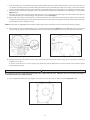
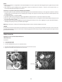
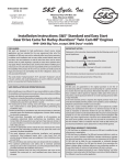
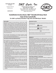
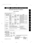
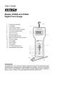
11-18-09
S&S Cycle, Inc
Copyright © 2009
by S&S® Cycle, Inc.
Phone: 608-627-1497 • Fax: 608-627-1488
Instruction 106-5893
®
.
All rights reserved.
Printed in the U.S.A.
14025 Cty Hwy G PO Box 215
Viola, Wisconsin 54664
Technical Service Phone: 608-627-TECH (8324)
Technical Service Email: [email protected]
Website: www.sscycle.com
Installation Instructions: S&S® Standard and Easy Start
Gear Drive Cams for Harley-Davidson® Twin Cam 88® Engines
DISCLAIMER:
S&S parts are designed for high performance, closed course, racing
applications and are intended for the very experienced rider only. The
installation of S&S parts may void or adversely affect your factory warranty.
In addition such installation and use may violate certain federal, state, and
local laws, rules and ordinances as well as other laws when used on motor
vehicles used on public highways, especially in states where pollution laws
may apply. Always check federal, state, and local laws before modifying your
motorcycle. It is the sole and exclusive responsibility of the user to determine
the suitability of the product for his or her use, and the user shall assume all
legal, personal injury risk and liability and all other obligations, duties, and
risks associated therewith.
The words Harley®, Harley-Davidson®, H-D®, Sportster®, Evolution®, and all
H-D part numbers and model designations are used in reference only. S&S
Cycle is not associated with Harley-Davidson, Inc.
IMPORTANT NOTICE:
Statements in this instruction sheet preceded by the following words are of
special significance.
WARNING
Means there is the possibility of injury to yourself or others.
CAUTION
Means there is the possibility of damage to the part or motorcycle.
NOTE
Other information of particular importance has been placed in italic type.
S&S recommends you take special notice of these items.
WARRANTY:
SAFE INSTALLATION AND OPERATION RULES:
Before installing your new S&S part it is your responsibility to read and follow
the installation and maintenance procedures in these instructions and follow
the basic rules below for your personal safety.
Gasoline is extremely flammable and explosive under certain conditions
and toxic when breathed. Do not smoke. Perform installation in a well
ventilated area away from open flames or sparks.
If motorcycle has been running, wait until engine and exhaust pipes
have cooled down to avoid getting burned before performing any
installation steps.
Before performing any installation steps disconnect battery to eliminate
potential sparks and inadvertent engagement of starter while working
on electrical components.
Read instructions thoroughly and carefully so all procedures are
completely understood before performing any installation steps.
Contact S&S with any questions you may have if any steps are unclear or
any abnormalities occur during installation or operation of motorcycle
with a S&S part on it.
Consult an appropriate service manual for your motorcycle for correct
disassembly and reassembly procedures for any parts that need to be
removed to facilitate installation.
Use good judgment when performing installation and operating
motorcycle. Good judgment begins with a clear head. Don’t let
alcohol, drugs or fatigue impair your judgment. Start installation
when you are fresh.
Be sure all federal, state and local laws are obeyed with the installation.
For optimum performance and safety and to minimize potential
damage to carb or other components, use all mounting hardware that is
provided and follow all installation instructions.
Motorcycle exhaust fumes are toxic and poisonous and must not be
breathed. Run motorcycle in a well ventilated area where fumes can
dissipate.
••
••
••
••
••
••
••
••
••
All S&S parts are guaranteed to the original purchaser to be free of
manufacturing defects in materials and workmanship for a period of twelve
(12) months from the date of purchase. Merchandise that fails to conform to
these conditions will be repaired or replaced at S&S’s option if the parts are
returned to us by the purchaser within the 12 month warranty period or within
10 days thereafter.
In the event warranty service is required, the original purchaser must call or
write S&S immediately with the problem. Some problems can be rectified by
a telephone call and need no further course of action.
A part that is suspect of being defective must not be replaced by a Dealer
without prior authorization from S&S. If it is deemed necessary for S&S to
make an evaluation to determine whether the part was defective, a return
authorization number must be obtained from S&S. The parts must be packaged
properly so as to not cause further damage and be returned prepaid to S&S
with a copy of the original invoice of purchase and a detailed letter outlining
the nature of the problem, how the part was used and the circumstances at
the time of failure. If after an evaluation has been made by S&S and the part
was found to be defective, repair, replacement or refund will be granted.
ADDITIONAL WARRANTY PROVISIONS:
(1) S&S shall have no obligation in the event an S&S part is modified by any
other person or organization.
(2) S&S shall have no obligation if an S&S part becomes defective in whole or in
part as a result of improper installation, improper maintenance, improper use,
abnormal operation, or any other misuse or mistreatment of the S&S part.
(3) S&S shall not be liable for any consequential or incidental damages
resulting from the failure of an S&S part, the breach of any warranties, the
failure to deliver, delay in delivery, delivery in non-conforming condition, or
for any other breach of contract or duty between S&S and a customer.
(4) S&S parts are designed exclusively for use in Harley-Davidson® and other
American v-twin motorcycles. S&S shall have no warranty or liability obligation
if an S&S part is used in any other application.
Specification for S&S® Gear Drive Camshaft for Harley-Davidson® Twin Cam 88® Engines
Cam
Name
Valve Timing
Open / Close
Valve Duration
Centerline
Lift @ TDC
Intake
Exhaust
Valve
Lift
Intake
Exhaust
Intake
Exhaust
52° / 20°
238°
252°
.510"
99°
106°
.187"
.179"
17°/19°
41°/17°
216°
238°
.550"
91°
102°
.178"
.170"
Intake
Exhaust
510G
20°/ 38°
551G
570G
20°/ 40°
55° / 20°
240°
255°
.570"
100°
107.5°
.187"
.179"
583G
5°/18°
58°/24°
203°
262°
.583"
96.5°
107°
.113"
.206"
585G
20°/ 45°
60° / 20°
245°
260°
.585"
102.5°
110°
.186"
.179"
625G
20°/ 55°
60° / 20°
255°
260°
.625"
107.5°
110°
.189"
.184"
640G
25°/ 60°
65° / 25°
265°
270°
.640"
107.5°
110°
.228"
.214
675G
25°/64°
70°/25°
269°
275°
.675"
109.5°
112.5°
.235"
.205"
Chart 1
INTRODUCTION
••
Pinion shaft run out must be verified before installing gear drive camshafts. (.003" max)
The S&S® gear drive cams offer many advantages over the original cam chain drive system:
Reduced maintenance. There are no chain guides or shoes to wear or replace and no debris from wearing guides or shoes in your engine oil.
Consistent cam timing. Cam gears are keyed with a light press fit. Chain and tensioner induced variations are no longer a problem.
Eliminating the chains and tensioners eliminates excessive side loading of cam bearings.
Critical sprocket alignment is unnecessary. Use of precision machined spacers is eliminated.
Maintain accurate valve timing when using high performance valve springs with higher spring forces.
Higher cam lifts can be used without decreasing cam base circle. Gear driven rear cam rotates in opposite direction from chain driven cam.
Lobes on front and rear cams never point toward each other, allowing increased lobe height.
••
••
••
••
••
••
Overview of EASY START camshafts (if equipped):
S&S has developed a unique product to assist starting with a Easy Start cam. The premise is simple: at cranking speeds a spring loaded decompression
lever holds the exhaust valve open slightly. Once the engine fires and exceeds 750 RPM, centrifugal force takes over and sends the lever to a retracted
position, allowing the engine to run normally.
Easy Start Gear Drive Cams
Important notes regarding Easy Start camshafts:
1- Expect a 40-60% drop in cranking compression when using these cams.
2- Cranking compression numbers are no longer a valid health check of the engine. We recommend performing a leak down test.
3- S&S recommends that you install new lifters when installing new cams
4- If any service work is performed and the lifters are not replaced, the lifters must be installed in the original position and orientation.
5- If the lifters have been disassembled or bled down for any purpose, the starter may have difficulty with the initial start. Although the
decompression lobe lifts the lifter body, the lifter is not pumped up and it will not lift the exhaust valve. You may need to remove the spark
plugs and crank the engine to get oil pressure to the lifters.
6- There is no service required with these cams. If you ever have the cams out for any reason, inspect the mechanism for wear and verify that the
lever operates smoothly.
2
COMPATIBILITY NOTES:
Pinion shaft run out must be verified before installing gear drive camshafts. (.003" max)
S&S® Gear Drive Cams are not compatible with camshafts designed for the stock chain cam drive. S&S Gear Drive Cams must be used with S&S gear
drive camshafts.
Except for the 510G, the gear driven camshaft kits are not compatible with stock pushrods or valve springs. S&S adjustable pushrod kit 93-5095 is
recommended for engines with stock length cylinders. Longer pushrods are available for engines with longer than stock cylinders. See the S&S catalog
for pushrods and valve springs.
S&S Camshaft Installation Kit 33-5163 is strongly recommended when installing S&S gear drive cams. The kit includes gaskets and bearings required for
installation, but does not include oil pump o-rings.
••
••
••
••
CAUTION
All S&S gear drive cams except for the 510G require that the stock valve springs be checked and if necessary, replaced with high lift spring
kits. Some high lift spring kits require clearance checks and may require cylinder head modifications to prevent contact between top
collar and valve seal, and to achieve correct installed height. See the instructions with your spring kit for exact specifications.
•• When using S&S gear drive camshafts with stock Harley-Davidson® pistons, valve-to-piston clearance may need to be checked. Clearance should be at
least .060" intake and .080" exhaust.
•• If stock Harley-Davidson® heads are decked, valve to piston clearance must be checked. If insufficient clearance is found, valve pockets must be modified.
Clearance should be a minimum of .060".
•• When using S&S pistons with S&S heads which are unmodified or have been decked no more than .062", no additional valve to piston clearancing will
be required.
INSTALLATION
1- Remove Cam Chain Drive
NOTES:
Changing camshafts and cam drives in Twin Cam 88® engines is different than in previous engines. Procedure requires use of a hydraulic press and some
special tools. Installation should be done by an experienced mechanic with access to a factory service manual and all required tools.
Tighten all fasteners to correct specifications and in order described. Always use an accurate torque wrench.
••
••
CAUTION
Incorrect installation can cause engine damage not covered under warranty.
WARNING
Failure to install components correctly can result in sudden engine seizure. Engine seizure may result in serious injury to motorcycle
operator, passenger, or others.
A- Disconnect battery ground cable to eliminate potential sparks and inadvertent engagement of starter while working on motorcycle.
B- Remove spark plugs and pushrod cover clips. Collapse pushrod covers to expose pushrods.
C- Safely elevate and stabilize rear of motorcycle. Place transmission in high gear. Turn rear wheel to rotate engine until both lifters and
pushrods for either cylinder are at lowest point on camshaft (TDC of compression stroke). Both intake and exhaust pushrods for that
cylinder will not be under pressure from the valve springs and will rotate with light finger pressure.
NOTE: 510G camshafts may use stock style non-adjustable pushrods instead of adjustable pushrods. If installing non-adjustable pushrods, disassemble
and assemble rocker box per Harley-Davidson® instructions. All other S&S® gear drive cams require installing adjustable pushrods. As a time-saving
measure, the stock pushrods can be removed with bolt cutters. Be sure to heed cautions and warnings in these instructions.
D- Cut pushrods for cylinder that is at TDC with bolt cutter and remove pushrods and pushrod covers from engine. Rotate engine to place
pushrods for other cylinder at their lowest point. Cut and remove remaining pushrods.
CAUTION
Cutting pushrods with a saw or cutoff wheel may result in debris entering engine, causing extensive engine damage not covered under warranty.
WARNING
Cutting pushrods without releasing spring pressure, by rotating engine until tappets are at lowest point of travel, can result in bodily injury.
3
E- Remove pushrod and lifter covers from crankcase.
F- Remove engine cam cover and gasket. It is not necessary to remove ignition sensor from cover. Secure lifters with a tool made from a large
binder clip. See Picture 1 below left.
G- Remove bolts and washers from cam drive sprocket and crankshaft sprocket.
NOTE: S&S® recommends using Harley-Davidson® sprocket locking tool H-D® #42314 to secure sprockets while bolts are being removed. See Picture 2
below right.
Picture 2
Picture 1
H- Use Harley-Davidson® cam chain tensioner unloader H-D® #42313 to move tensioner away from primary cam chain. Secure tensioner with
retention pin. See Picture 3 below left.
I- Working gradually around edge of each sprocket, carefully pry sprockets loose. Remove sprocket and chain assembly.
J- Remove chain guide. See Picture 4 below right.
Picture 3
Picture 4
All references to Harley-Davidson® part numbers is for identification purposes only. We in no way are implying that any of S&S® Cycle’s products are
original equipment parts or that they are equivalent to the corresponding Harley-Davidson® part number shown.
4
K- Following sequence shown, alternately loosen and remove oil pump bolts. See Figure 1 below left.
L- Following sequence shown, alternately loosen and remove cam support plate bolts. See Figure 2 below right.
Figure 1
Figure 2
CAUTION
Failure to remove and install bolts according to correct procedure may result in parts damage not covered under warranty.
M- Carefully remove cam support plate assembly from case.
All references to Harley-Davidson® part numbers is for identification purposes only. We in no way are implying that any of S&S® Cycle’s products are
original equipment parts or that they are equivalent to the corresponding Harley-Davidson® part number shown.
NOTE: It is not necessary to remove oil pump from engine to complete this installation unless grinding in gear case must be performed for clearancing. If
grinding is to be done all gear case components must be removed and all holes taped off with duct tape to avoid contamination of engine with chips.
N- Use Harley-Davidson® cam chain tensioner unloader H-D® #42313 to move tensioner away from secondary cam chain. Secure tensioner by
inserting second retention pin through front of support plate.
O- Remove bearing retainer screws and bearing retainer from cam support plate.
P- With cam support plate positioned securely in a hydraulic press, use Harley-Davidson® camshaft remover/installer H-D® #43644 to press
both camshafts and bearings from support plate simultaneously.
NOTES:
Cam bearings may have a loose fit in cam support plate. Camshaft and bearing assemblies may drop out when beginning pressing procedure. Camshafts
with roller style bearings will be loose and drop out of support plate.
The S&S® Gear Drive Cams require that ball bearings be used for both front and rear camshaft outer bearings. The roller bearing used for the rear
camshaft in some stock engines has too much internal clearance. This allows center to center distance of gears to vary, causing excessive gear noise. Since
the gear drive does not exert a large side load on the rear camshaft, the higher load handling capacity of the roller style bearing is not required.
••
••
Q- Use Harley-Davidson® cam chain tensioner unloader H-D® #42313 to remove retention pin from either tensioner. Allow tensioner to
completely relax. Remove retaining ring and tensioner assembly from cam support plate. Repeat this procedure for remaining tensioner.
2- Install Gear Drive Cams
CAUTION
Check pinion shaft runout. Indicate end of pinion shaft at cam support plate bushing surface and rotate engine; reading must be .003” or
less total indicated runout (TIR). If reading is greater than .003” TIR the crankshaft must be repaired or replaced to correct excess runout
before installing gear drive cams. Failure to correct excess runout may lead to engine damage not covered under S&S warranty.
NOTE: Do not reuse cam bearings. If S&S Camshaft Installation Kit 33-5163 is not being used, new bearings should be obtained from another source and
installed with new camshafts. The S&S Gear Drive Cams require that ball bearings be used for both front and rear camshaft outer bearings.
5
A- Apply assembly lube to outer races of cam bearings and bearing bores in support plate. With cam support plate positioned securely in a
hydraulic press, use Harley-Davidson® camshaft remover/installer H-D® #43644 to install both bearings. See Picture 5 below left.
NOTE: Check clearance between bearing retainer and woodruff keys securing inner gears to cams. Remove material from retainer, to provide .030"
clearance between key and retainer. See Picture 6 below.
If additional clearance is required, remove
material from areas indicated to provide
.030" clearance between key and retainer .
Picture 5
Picture 6
B- Align hole in bearing retainer with oil passage in support plate. Install bearing retainer screws with a drop of blue Loctite® threadlock 242
or 243 and tighten screws to 20-30 in-lbs. torque.
C. Apply assembly lube to outer bearing surface of front (shorter) camshaft and inner race of front bearing. Support bearing by inner race and
press camshaft all the way into bearing. Install retaining ring on outer end of front camshaft.
NOTE: Do not reuse retaining ring. If S&S Camshaft Installation Kit 33-5163 is not being used, a new retaining ring be obtained from another source and
installed with new camshaft.
D- Apply assembly lube to outer bearing surface of rear (longer) camshaft and inner race of rear bearing. Support bearing by inner race and
with camshaft gear timing marks aligned (See Figure 3 below), press camshaft all the way into bearing.
Figure 3
All references to Harley-Davidson® part numbers is for identification purposes only. We in no way are implying that any of S&S® Cycle’s products are
original equipment parts or that they are equivalent to the corresponding H-D® part number shown.
6
E- When using 551G, 583G, 585G, 625G, or 640G camshafts (33-5168, 33-5170, or 33-5172) clearance between pinion bearing boss and rear
cam lobe must be checked. See Pictures 7 & 8 below. Remove just enough material to provide .030" clearance between top of cam lobe
and pinion bearing boss when camshaft is rotated in inner needle bearing. Also check clearance between all cam lobes and tappet guide
bosses. To avoid contamination of engine with chips, we recommend that all holes in the gear case be taped off with duct tape and that
gear case be thoroughly cleaned with parts cleaner or solvent after clearancing is performed.
Picture 7
Picture 8
F- Carefully remove camshaft needle bearings from crankcase with Harley-Davidson® camshaft needle bearing remover/installer H-D®
#42325, and replace them with new bearings provided in S&S Camshaft Installation Kit 33-5163, or with bearings from another source.
Cam bearings must be Torrington B148 full complement bearing or equivalent.
NOTE: Before reinstalling cam support plate, make sure oil pump O-rings are in good condition and remain in place during following procedure. Replace
worn or damaged O-rings if necessary.
G- Apply a thin layer of assembly lube to cam journals, lobe surfaces, and inner bearing surfaces. Thoroughly lubricate decompression lever, if
equipped. Align camshafts with needle bearings and carefully slide support plate over crankcase dowels.
NOTE: Support plate assembly should slide into place without resistance. If resistance is encountered, determine cause and correct problem before
proceeding. Do not force support plate into position!
H- Loosely install support plate screws with a drop of Loctite® threadlock 242 or 243 (blue). Alternately tighten screws to 95 in-lbs. torque
following sequence shown. See Figure 2 Page 5.
CAUTION
Support plate screws that pass through alignment dowels (See positions 1 & 2 in Figure 2) can be easily stripped when applying maximum
120 in-lbs. torque as recommended by Harley-Davidson®.
I- Install oil pump mounting bolts with a drop of Loctite® threadlock 242 or 243 (blue) according to procedure found in factory service
manual: Gently bottom screws, then back them out 1⁄4 turn. Center oil pump by rotating engine by hand while snugging down screws.
Alternately tighten bolts to 95 in-lbs. torque in sequence shown. See Figure 1 Page 5. Before moving forward, verify that inner drive gears
rotate freely and no binding is present.
NOTES:
Crankshaft and cam drive gears have a light press fit on their respective shafts. Start gears squarely on their shafts and use their mounting bolts to pull
them all the way into position.
Make sure that no metal burrs are raised when installing the gear sets. Burrs can form underneath the gear causing excessive gear run out.
••
••
Checking the inner cam gear and outer drive gear sets for backlash:
It is important to check the inner 31 teeth gear set and the outer drive gear set (pinion 31 teeth gear and cam drive 62 teeth gear) for the correct
backlash before installing the rest of the valve train components. Backlash, the measure of free play between the gear set, must be checked with
no loading applied to the cams and in the four different camshaft positions. To check the backlash of the inner cam gears, lock the front cam into a
position by applying a force to the cam lobe. Measure the backlash by moving the rear cam set back and forth. To check backlash in the outer drive
gear set, rotate the 62 teeth cam drive gear back and forth while keeping the pinion gear locked in one place with the engine. The minimal required
backlash for the gear sets should be between .0005” and .001”and no more than .002” for cold gears. The both gear sets should roll freely with no
radial or axial binding. If when checking backlash the gear mesh shows less than .0005” of backlash then a smaller crankshaft gear size 33-4160X
for the outer gears or 33-4272RX for the inner gears should be used. Gear sets with less than .0005” of backlash may whine when run and can cause
tooth wear excessive heat generation and gear failure resulting in engine damage. Gear backlash greater than .002” can cause excessive gear noise
or clicking caused by the reversing of the forces applied by the lifter springs onto the gears, use the oversized crankshaft gear 33-4160Z for the outer
gears and 33-4272RZ for the inner gears to correct this condition.
7
J- Place crankshaft gear on crankshaft with timing mark outward. Apply a drop of red Loctite® threadlock 262, 271 or 272 to threads of 5⁄16"-18
x 3⁄4" Grade 8 crankshaft gear bolt, provided in S&S® Camshaft Kit 33-5163 or obtained from another source. Apply a drop of clean 20W-50
engine oil under bolt flange. Using the washer removed in disassembly step G, install crankshaft gear bolt and tighten to 25 ft-lbs. torque.
K- If necessary, place transmission in high gear and turn rear wheel to rotate engine until timing mark on crankshaft gear is in position. See
Figure 4 below.
L- Place drive gear key in rear camshaft. Position cam drive gear on rear camshaft and key with timing mark outward. Rotate drive gear and
camshafts until drive gear and crankshaft gear timing marks are aligned. See Figure 4.
M- Apply a drop of red Loctite® threadlock 262, 271 or 272 to threads of 3⁄8"-24 x 1.75 Grade 8 cam drive gear bolt. Apply a drop of clean 20W50 engine oil under bolt flange. Using thick washer provided, install cam drive gear bolt and tighten to 34 ft-lbs. torque. Verify that out gear
drives rotate freely and no binding is present.
NOTE: Drive gear cams are slightly larger than stock drive sprocket and needs to be checked for interference with cam cover before proceeding.
N- Press a small piece of clay or kneadable putty on cam cover mounting boss shown. See Figure 5 below. Carefully hold cover and cover gasket
in position against crankcase. Install mounting bolts (4) near corners of cover finger tight. Push or tap cam cover towards front of engine.
Figure 4
Figure 5
O- Carefully remove cam cover. Determine cover-to-gear clearance by measuring impression left in clay by gear at its thinnest point. Clearance
should be .030" or more.
If clearance is less than .030", or if cover contacts gear, remove only enough material from cam cover to obtain correct clearance. Repeat
steps M and N if necessary.
CAUTION
Be careful not to grind too deeply and break through to the outside of the cam cover. Damage to cam cover caused by removing too
much material is not covered under warranty.
P- Use a new gasket and install cam cover. Tighten cover bolts to 90-120 in-lbs. torque in sequence shown. See Figure 6 below.
Figure 6
8
Q- Remove clips to release lifters. If necessary, place transmission in high gear and turn rear wheel to rotate engine until both lifters of front
cylinder are at lowest point on camshaft. The engine is now at TDC of compression stroke for front piston. If equipped with compression
releases, you must use extra care when adjusting pushrods. Because the decompression lobe is near TDC, it is possible to adjust the
pushrod while the tappet is on the lobe if it is not exactly at TDC. This will cause incorrect exhaust pushrod adjustment. To verify correct
position, you can rotate the engine in the forward direction and feel for the exhaust tappet to slightly lift ( about .030”) and set back down
on base circle. This is the proper point to adjust the pushrods.
R- Loosen locknuts on adjustable pushrods and turn adjusters to make all rods as short as possible.
S- Longer S&S® pushrods are for exhaust valves, and shorter ones are for intake. Pass one long and one short pushrod through assembled
pushrod covers. Place pushrod and cover assemblies through lifter cover. Inner tappet hole is for intake pushrod, and outer tappet hole is
for exhaust pushrod. While holding a new gasket under lifter cover, install push rod, pushrod cover, lifter cover, and gasket as an assembly
on crankcase. Tighten lifter cover screws to 95 in-lbs. torque.
NOTE: If using unmodified original tappets, perform steps 3-A thru 3-D to adjust pushrods, see below. If S&S HL2T kit has been installed in tappets, proceed
to steps 4-A thru 4-F. See below.
3- Pushrod Adjustment Procedure - For Unmodified Stock Tappets
A- Turn adjuster screw to lengthen exhaust pushrod until pushrod has no vertical movement but still rotates with light finger pressure. Extend
pushrod by rotating adjuster screw an additional 24 flats and secure adjuster screw with locknut.
B- Repeat step 2-S for intake pushrod.
C- Front lifters should bleed down in 5-10 minutes, allowing pushrods to be rotated with light finger pressure. Extend pushrod covers and
install cover clips.
CAUTION
Rotating engine before lifters have bled down may damage pushrods and other components not covered under warranty.
D- Rotate engine until it is at TDC of compression stroke for rear piston (following procedure outlined above). Repeat steps R-T for
rear pushrods.
4- Pushrod Adjustment Procedure - For Tappets With HL2T Kit Installed
A- Remove clips to release lifters. If necessary, place transmission in high gear and turn rear wheel to rotate engine until both lifters of front
cylinder are at lowest point on camshaft. The engine is now at TDC of compression stroke for front piston. If equipped with compression
releases, you must use extra care when adjusting pushrods. Because the decompression lobe is near TDC, it is possible to adjust the
pushrod while the tappet is on the lobe if it is not exactly at TDC. This will cause incorrect exhaust pushrod adjustment. To verify correct
position, you can rotate the engine in the forward direction and feel for the exhaust tappet to slightly lift ( about .030”) and set back down
on base circle. This is the proper point to adjust the pushrods.
B- Extend pushrod adjustment, collapsing lifter until piston assembly is in contact with HL2T spacer and pushrod is tight. If tappets contain
oil, as when pushrods are readjusted after engine has been run, or if all oil was not removed during HL2T installation, extend pushrod
adjustment until valve is open (about five additional turns of adjusting screw). Allow 5 minutes for hydraulic unit to bleed down. If pushrod
can be turned with fingers after bleeding down, lifter is not completely collapsed, and this step must be repeated.
NOTE: Perform this operation on one cylinder at a time. Do not turn engine until pushrod adjustment is complete.
CAUTION
Turning engine while valve is held off the seat could result in valve to valve or valve to piston contact and serious valve train damage.
C- Loosen pushrod adjustment until pushrod can be rotated with the fingers with slight drag. Pushrod now has zero lash.
NOTES:
Shortening pushrod adjuster an additional six flats or one full turn from zero lash often results in quieter pushrod operation. This provides additional
travel for the hydraulic piston assembly, which can improve the ability of the hydraulic unit to maintain zero lash under normal operating conditions.
Harley-Davidson® Twin Cam 88® lifters require HL2T Kit 33-5339 for 1986 and later engines.
D- Tighten lock nut and recheck pushrod adjustment to insure that it is still correct.
E- Follow the same procedure for all four pushrods.
F- Replace any remaining parts removed to facilitate gear drive cams installation. Check engine oil level. Start engine and check for leaks.
••
••
9
NOTES:
After a few hundred miles it is a good idea to recheck pushrod adjustment in a new engine as valve train may tighten up due to gasket compression and
valve seat wear.
Upon initial start up after modification, HL2T equipped lifters may be somewhat noisy for 10-20 miles. If lifters are still noisy after 20 miles it is
recommended that pushrods be adjusted 1⁄2 turn looser.
Special notes on operation of motorcycle with Easy Start camshafts:
All stock EFI engines must have a minimum 70 PSI of cranking compression, checked with the throttle open. If the engine does not have the minimum
cranking compression, the ECU may not fire the spark plugs when starting. If the engine does not have 70 PSI, please call our technical department toll
free at 866-244-2673.
The engine idle should be set at 1000-1100 RPM.
If your bike is carbureted, the starting routine may be slightly different, allow yourself time to experiment to find the best method.
When the engine is turned off, you may hear a slight click. This is the decompression lever resetting, and is normal. Occasionally this may be quite loud
but is still normal and does no harm.
If you allow engine speed to go below 900 RPM, you may hear clicking as the decompression lever starts engaging. Your engine may stall if this happens.
If this happens frequently, the idle speed should be adjusted higher.
••
••
••
••
••
••
••
NOTE: Engine may require several miles at normal operating temperature for lifters to fill with oil and quiet valve train.
Service
If crankshaft or cam drive sprocket needs to be removed, S&S® recommends using a small wheel puller like NAPA® #775-9064. Loosen and unscrew
gear bolt until bolt flange is about .600" from shaft. To avoid damaging shaft internal threads, let puller screw push against head of gear bolt until
gear breaks free from shaft.
Service Bulletin
Hydraulic Tensioner, Oil Hole Block Off Plates Kit
S&S PN 106-5723
Kit Contents:
••
••
••
1 Plate S&S PN 33-4264
1 Plate S&S PN 33-4265
4 Screws, Torx Button Head, ¼”-20 x ¾” S&S PN 50-0288-S
1- Install the block off plates where the front and rear chain tensioners were located.
2- Apply blue threadlock and torque screws to 100-120 in lbs.
Rear Plate
Front Plate
Front cam support plate view
Rear cam support plate view
10
S&S® Gear Drive Cams Assembly Parts
1- Gasket, Cam Cover................................................................31-2032
2- Bearing, Needle, Inner Cam (2).........................................31-4080
3- Bearing, Outer Cam, Ball.....................................................31-4081
4- Gear, Pinion.............................................................................33-4160
5- Gear, Cam Drive
(Includes reference #12, 13 & 16)....................................33-4271
6- Gear, Camshaft, Front
(Includes reference #15)..................................................33-4272F
7- Gear, Camshaft, Rear
(Includes reference #15)..................................................33-4272R
8- Kit, Gear Drive Cams
(Includes reference #4-7, 12, 13, 15 & 16).....................33-4275
9- Kit, Gear Drive Cams Outer Gears
(Includes reference #4, 5, 12, 13 & 16)...........................33-4276
10-Kit, Chain Drive Camshaft Installation
(Includes reference #1-3, 11 & 14)...................................33-5163
11-Screw, HHC 5⁄16"-18 x 3⁄4".......................................................50-0100
12-Screw, SHC 3⁄8" -24 x 13⁄4".....................................................50-0132
13-Washer, Flat 3⁄8"x 11⁄8"x .225"...............................................50-7056
14-Ring, Retaining.......................................................................50-8061
15-Key, Woodruff .125 x .5 (2)..................................................50-8223
16-Key, .188 x .150 x .57.............................................................50-8226
19-Camshaft Kits
Kit, Camshaft, 510G..............................................................33-5174
Kit, Camshaft, 570G..............................................................33-5166
Kit, Camshaft, 585G..............................................................33-5168
Kit, Camshaft, 625G..............................................................33-5170
Kit, Camshaft, 640G..............................................................33-5172
11
Easy Start Camshaft Kits
Kit, Camshaft, Easy Start, 551G......................................106-5441
Kit, Camshaft, Easy Start, 570G......................................106-5246
Kit, Camshaft, Easy Start, 583G......................................106-5858
Kit, Camshaft, Easy Start, 585G......................................106-5250
Kit, Camshaft, Easy Start, 625G......................................106-4839
Kit, Camshaft, Easy Start, 640G......................................106-5254
Kit, Camshaft, Easy Start, 675G......................................106-5242