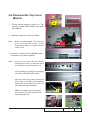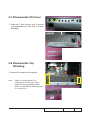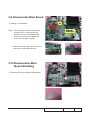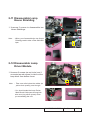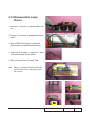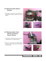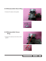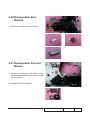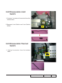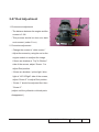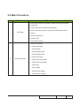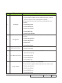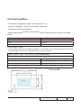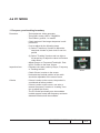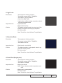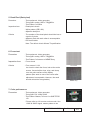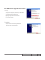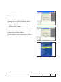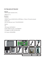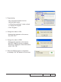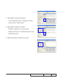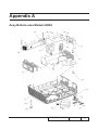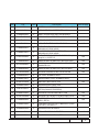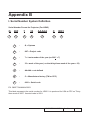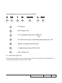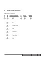
1
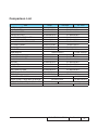
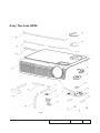
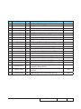
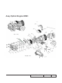
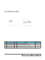
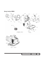
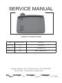
SERVICE MANUAL
HD65/GT-7000/HD700X
Date
Revise Version
Description
2007.10.24
V1.0
Initial Issue
2008.02.15
V2.0
Add Appendix A
2008.09.24
V3.0
Add GT-7000/HD700X
Copyright September, 2008. All Rights Reserved P/N: 36.89F05G001
95.89F01G00A ; 95.89F01GC0A ; 95.88N01GC0E.
SI :
TSE:
Check:
Approved:
Preface
This manual is applied to HD65/GT-7000/HD700X projection system. The manual gives
you a brief description of basic technical information to help in service and maintain the
product.
Your customers will appreciate the quick response time when you immediately identify
problems that occur with our products. We expect your customers will appreciate the
service that you offer them.
This manual is for technicians and people who have an electronic background. Please
send the product back to the distributor for repairing and do not attempt to do anything that
is complex or is not mentioned in the troubleshooting.
Notice:
The information found in this manual is subject to change without prior notice. Any
subsequent changes made to the data herein will be incorporated in future edition.
HD65/GT-7000/HD700X Service Manual
Copyright September 2008
All Rights Reserved
Manual Version 3.0
HD65/GT-7000/HD700X
Confidential
II
Comparison List
Part
BOTTOM CASE
LAMP COVER
ELEVATOR STEP
ELEVATOR FOOT
LINKER ELEVATOR BUTTON
FIX FOOT RUBBER
ADJUSTABLE FOOT RUBBER
I/O COVER LABEL
ZOOM RING
IO COVER
MAIN BOARD
TOP CASE
FOCUS RING COVER
ZOOM RING COVER
KEYPAD
4 WAY KEY
ENTER KEY
LED LENS KEYPAD
CARTON AB THEMESCENE LOGO
LENS CAP
CABLE POWER CORD
QUICK START CARD MULTILINGUAL
INFRARED REMOTE CONTROLLER
USER’S GUIDE MULTILINGUAL
HD65
HD700X
GT-7000
51.88N07G011
51.88N07G013
70.89F28GR01
70.89F32GR01
51.88N24G011
51.88N24G001
51.88N22G011
51.88N22G001
51.88N21G011
51.88N21G001
52.88N06G011
52.88N06G001
52.88N07G011
52.88N07G001
35.89F01G001
35.89F01G011
51.88N05G011
51.88N05G001
51.89F01G001
51.89F01G011
70.89F30GR01
70.89F33GR01
51.88N06G061
51.88N06G0A1
51.88N06G0D1
51.88N10G011
51.88N10G001
51.88N12G011
51.88N12G001
51.88N16G011
51.88N16G001
51.88N17G011
51.88N17G001
51.88N18G011
51.88N18G001
51.88N19G011
51.88N19G001
55.89F02G001
55.89F01G001
75.89F02G001
75.88N04G001
42.50112G001
42.53506G001
36.89F03G001
36.89F03G012
45.89F01G001
45.89F01G002
36.89F04G001
36.89F04G031
HD65/GT-7000/HD700X
Confidential
III
Table of Content
Chapter 1
Introduction
Highlight
1-1
Compatible Mode
1-2
Chapter 2 Disassembly Process
Equipment Needed & Product Overview
2-1
Disassemble Lamp Cover
2-2
Disassemble Lamp Module
2-2
Disassemble Top Cover Module
2-3
Disassemble Keypad Board and Keypad
2-4
Disassemble IR Sensor
2-4
Disassemble I/O Cover
2-5
Disassemble Top Shielding
2-5
Disassemble Main Board Module
2-6
Disassemble Main Board Shielding
2-6
Disassemble Lamp House Shielding
2-7
Disassemble Lamp Driver Module
2-7
Disassemble Engine Module
2-8
Disassemble Color Wheel and Photo Sensor Board
2-8
Disassemble Heat Sink
2-9
Disassemble DMD Module
2-9
Disassemble Zoom Ring
2-10
Disassemble Focus Ring
2-10
Disassemble Rod Module
2-11
Disassemble Fan and Blower 2-11
Disassemble Limit Switch
2-12
HD65/GT-7000/HD700X
Confidential
IV
Disassemble Thermal Switch
2-12
Disassemble LVPS 2-13
Disassemble Bottom Shielding
2-13
Chapter 3
Troubleshooting
Chapter 4
LED Lighting Message
Main Procedure
3-1
3-2
Function Test & Alignment Procedure
Test Equipment Needed
4-1
Service Mode
4-1
OSD Reset
4-1
Test Condition
4-2
Test Inspection Procedure
4-3
PC Mode
4-3
Video Performance
4-7
Optical Performance Measure
4-8
Other
4-9
Chapter 5 Firmware Upgrade Equipment Needed
5-1
DLP Composer Lite Setup Procedure
5-2
USB Driver Upgrade Procedure
5-4
Firmware Upgrade Procedure
5-5
Chapter 6 EDID Upgrade
EDID Introduction
6-1
6-2
Equipment Needed
HD65/GT-7000/HD700X
Confidential
V
Setup Procedure
6-3
EDID Key-In Procedure
6-3
Appendix A Exploded Image I
Appendix B Serial Number System Definition XVII
PCBA Code Definition XVIII
HD65/GT-7000/HD700X
Confidential
VI
Chapter 1
Introduction
1-1 Highlight
No
Item
Description
1
Dimension (WxHxD)
- 10.2 x 2.9 x 7.4 inches (259. x 73 x 188. mm)
2
Weight
- < 4.5 Lb
3
Power Supply
- Universal 100—240 VAC+/-10%, 50-60 Hz with PFC input
4
Power consumption
- 265W+/-10%@110Vac(full mode)
- < 9W(Stand by)
5
Resolution
- 1280x720
6
Brightness
- Typical 1300 ANSI lm
- Minimum 1100 ANSI lm
7
Contrast
- Typical: 1800:1
- Minimum:
�����������������
1200:1
8
Uniformity
- Typical : 80%
- Minimum : 65%���������
9
Throw ratio
- 1.55 ~1.70 (Projection Distance/Image Width)
10
Projection lens
- YM09W, F/# = 2.44~2.58 at 2.36m, f = 21.8 ~ 23.8mm, 1.1X
11
Lamp life
- 3000/2000 (����������������������
STD Mode��������������
/Bright Mode)
12
Tolerance
- Throw ratio <= +/- 5%
13
Color wheel
- 6 segments R100C23B72G90M30Y45, 3X
14
Lamp
- 180W Phoenix Lamp
15
Temperature
16
Altitude
- Operating: 5°C -- 35°C (Satisfied engineering specification &
functions)
- Storage: -10°C-- 60°C
- Operating:
����������������������������������������������
0~2,500 ft 5°C~35°C for Bright mode
(5°C~40°C for STD mode)
2,500~5,000 ft 5°C~30°C
5,000~10,000 ft 5°C~25°C
- Storage
������������������
:40,000 ft
HD65/GT-7000/HD700X Confidential
1-
No
17
18
19
Item
Description
- Operating: 5°C -- 35°C , 0 - 80 %RH (Max.), non-condensing
- Storage: -10°C -- 60°C , 0 - 80 %RH (Max.), non-condensing
Maximum Humidity
Video compatibility
- NTSC: M (3.58MHz), 4.43 MHz, 480i/p @60Hz
PAL: B, D, G, H, I, M, N, 576i/p @50Hz
SECAM: B, D, G, K, K1, L
HDTV: 480p, 576p, 720p, 1080i(50/60 Hz),1080P(50/60 Hz)
Support SCART RGB via D-SUB (VGA)����������������������������������
Cooling System
- Advanced Air Flow
Two motor fans (one 4520 blower fan for lamp, one 6020
axial fan for system)
Temperature control circuits with adaptive voltage control fan
speed
Max touch temperature follows UL60950-1 regulation
1-2 Compatible Mode
Analog
Compatibility
VGA
SXGA
XGA
Resolution
V-Sync [Hz]
640x350
70
640x350
85
640x400
85
640x480
640x480
640x480
60
72
75
640x480
85
720x400
70
720x400
85
800x600
800x600
800x600
800x600
800x600
1024x768
56
60
72
75
85
60
1024x768
70
1024x768
1024x768
75
85
HD65/GT-7000/HD700X Confidential
1-
Compatibility
Resolution
V-Sync [Hz]
HD
1280x720
1152x864
1152x864
1152x864
1280x1024
1280x1024
1280x1024
1400x1050
1600x1200
640x480
640x480
640x480
640x480
800x600
800x600
800x600
1024x768
1024x768
1024x768
1024x768
1280x768
1280x768
1280x720
1280x1024
1280x1024
60
70
75
85
60
75
85
60
60
60
72
75
85
60
75
85
60
70
75
85
60
70
60
60
75
1400x1050
60
1600x1200
60
640x480
640x480
640x480
800x600
800x600
800x600
1024x768
1024x768
1024x768
1024x768
72
75
85
60
75
85
60
70
75
85
SXGA
SXGA+
UXGA
Power Book G4VGA
Power Book G4SXGA
Power Book G4XGA
Power Book G4WXGA
Power Book G4HD
Power Book G4SXGA+
Power Book G4UXGA
Power G4-VGA
Power G4-SXGA
Power G4-XGA
HD65/GT-7000/HD700X Confidential
1-
Compatibility
Resolution
V-Sync [Hz]
Power G4WXGA
1280x768
60
1280x1024
1280x1024
1600x1200
1024x768
60
75
60
60
Resolution
V-Sync [Hz]
640x480
60
640x480
72
640x480
75
640x480
85
720x400
70
SXGA+
800x600
800x600
800x600
1024x768
1024x768
1024x768
1280x1024
1280x1024
1400x1050
60
72
75
60
70
75
60
75
60
UXGA
1600x1200
60
1280x720
1280x720
60
50
1920x1080
60
1920x1080
24
1920x1080
50
Power G4-HD
Power G4-UXGA
iMAC-XGA
Digital
Compatibility
VGA
SXGA
XGA
Wide
HD65/GT-7000/HD700X Confidential
1-
Chapter 2
Disassembly Process
2-1 Equipment Needed & Product Overview
1. Screw Bit (+) :105
2. Screw Bit (+) :107
3. Screw Bit (-) :107
4. Hex Sleeves 5 mm
5. Tweezers
6. HD65/GT-7000/HD700X unit
* Before you start: This process is protective level II. Operators should wear electrostatic chains.
* Note: If you need to replace the main board, you have to get into service mode and record the
lamp usage hour.
HD65/GT-7000/HD700X
Confidential
2-
2-2 Disassemble Lamp
Cover
1. Unscrew 2 screws on the lamp cover
2-3 Disassemble Lamp
Module
1. Unscrew 2 screws.
HD65/GT-7000/HD700X Confidential
2-
2-4 Disassemble Top Cover
Module
1. Press yellow square region on Top
Cover to make Zoom Ring Cover leap
from fillister.
2. Unscrew 4 screws on the unit base.
Note: - W
hen you disassemble Top Cover,you
must disassemble Lamp Cover
first,because there is 1 screw under the
Lamp Cover.
3. Unscrew 3 screws on the besides and 3
connectors (as yellow square).
Note: - P
ush the top cover (as the parallel
direction),then pull it up,because there
are 8 tenons (as green square) in it.
- A
void damage by pulling and draging
IR cable and keypad FPC cable.
- Hold the CNNT plug when pulling the
FPC cable is strongly recommended.
Pulling the cable directly from the unit
will cause the cable damages.
- Make sure cables pass through the
wire mounts (as violet square) when
assembling the unit.
HD65/GT-7000/HD700X
Confidential
2-
2-5 Disassemble Keypad
Board and Keypad
1. Unscrew 3 screws to disassemble the
Keypad Board.
2. Separate the Keypads from the top cover.
Note: - Make sure cables plug into the correct
ports when assembling the unit.
2-6 Disassemble IR Sensor
1. Use tweezers to take off the black film
tape,then press two tenons to disassemble
the IR Sensor.The other disassemble is same
as above.
HD65/GT-7000/HD700X Confidential
2-
2-7 Disassemble I/O Cover
1. Unscrew 2 hex screws and 2 screws
to disassemble I/O cover and I/O cover
Shielding.
2-8 Disassemble Top
Shielding
1. Unscrew 3 screws on the system.
Note: - When you assemble the Top
shielding,you should place the 2
edges into the gap between Main
Board and Main Board Shielding.(refer
to 2-9 and 2-10)
HD65/GT-7000/HD700X
Confidential
2-
2-9 Disassemble Main Board
1. Unplug 7 connectors.
Note: - First unplug 5 connectors(as yellow
squares) and 1 connector(as red
square),then push the Main Board
as the red arrow,at last unplug the
connector (as green square).
-M
ake sure cables plug into the correct
ports when assembling the unit.
2-10 Disassemble Main
Board Shielding
1. Unscrew 5 hex screws on the system.
HD65/GT-7000/HD700X Confidential
2-
2-11 Disassemble Lamp
House Shielding
1. Unscrew 5 screws to disassemble two
House Shieldings.
Note: - W
hen you disassemble the top House
Shieding,need to take off the white film
tape.
2-12 Disassemble Lamp
Driver Module
1. Unscrew 2 screws (as red circle) and 1
connector(as red square) to take out the
lamp driver from bottom cover.
Note: - T
ake care which place the cables (as
yellow dots square) pass through.
- You should make the Lamp Driver-
Main Board Cable pass through the
wire mout (as yellow square) when you assembling the unit.
HD65/GT-7000/HD700X
Confidential
2-
2-13 Disassemble Lamp
Driver
1. Unscrew 2 screws to disassemble Iron
Cut.
2. Unplug 1 connector to disassemble 5 pin cable.
3. Take off EMI Foil Copper to separate Sheetmetal and Sheetmetal protector.
4. Unscrew 4 screws to separate Lamp
Driver and Lamp Driver Holder.
5. Take off Lamp Driver Thermal Pad.
Note: - When you paste the Thermal Pad,you
should make sure it’s edge along with
the red line.
HD65/GT-7000/HD700X Confidential
2-
2-14 Disassemble Engine
Module
1. U nscrew 4 screws on the System to
disassemble Engine Module and Wire
Mount.
Wire Mount
2-15 Disassemble Color
Wheel and Photo
Sensor Board
1. Unscrew 2 screws (as red circle) to
disassemble Color Wheel Module.
2. Unscrew 1 screw from Color Wheel Module
(as blue circle) and take out the Photo
Sensor Board.
HD65/GT-7000/HD700X
Confidential
2-
2-16 Disassemble Heat Sink
1. Unscrew 4 screws on the system.
2-17 Disassemble DMD
Module
1. Unscrew 4 screws on the system then
seperate the DMD Module.
HD65/GT-7000/HD700X Confidential
2-10
2-18 Disassemble Zoom Ring
1. Unscrew 2 screws on the system.
2-19 Disassemble Focus
Ring
1. Unscrew 3 screws (as red circle) on the
system.
HD65/GT-7000/HD700X
Confidential
2-11
2-20 Disassemble Rod
Module
1. Unscrew 3 screws on the system.
2-21 Disassemble Fan and
Blower
1. Unscrew 2 screws on the bottom base,
disassemble Fan,Blower and Duct module
on the system.
2. Separate the Duct Module.
HD65/GT-7000/HD700X Confidential
2-12
2-22 Disassemble Limit
Switch
1. Unscrew 1 screw and 1connector from the
bottom base.
2.Separate Limit Switch and Limit Switch
Holder.
2-23 Disassemble Thermal
Switch
1. Unplug 1connector from the bottom
base.
Thermal Switch
HD65/GT-7000/HD700X
Confidential
2-13
2-24 Disassemble LVPS
Module
1. Unscrew 3 hex screws(as red circle)
2 screws(as yellow circle) and 1 screw (as blue circle) to disassemble the LVPS
Module.
Note: - When you disassemble the Iron Cut,
you should use tweezers to raise it up,
from the hook.
- You should make the raised-dots side
of Iron Cut face to inner of the unit
when assemble it. (as red dot square).
Iron Cut
2-25 Disassemble Bottom
Shielding
1. Unscrew 1 hex screw (as blue circle) and
1 screw(as red circle) on the bottom cover,
disassemble the Bottom Shielding.
HD65/GT-7000/HD700X Confidential
2-14
2-26 Disassemble Elevator
1. Unscrew 2 screws inside of the bottom
cover and 1 screw outside of the bottom
cover.
2. Separate the rest Elevator module from
the bottom cover.
Note: - Use the sweezers to take off the short
spring.
HD65/GT-7000/HD700X
Confidential
2-15
2-27 Rod Adjustment
1. Environment adjustment
- The distance between the engine and the
screen is 2.1M.
screw 1
screw 2
- This process should be done at a dark
environment. (under 5 Lux)
2. Procedure adjustment
- Change the screen to “white screen.”
- Adjust the screws by using the rod on the
engine module to readjust the image.
If there are shadow at “Top” & “Bottom” side of the screen, adjust “Screw 1” to
adjust Rod position.
- If there are shadow / yellow light / blue light at “Lift” &“Right” side of the screen,
adjust “Screw 2” to adjust Rod position.
- “Screw 1” should be adjusted first, then “Screw 2 ”.
(adjust until the yellowish or bluish parts disappeared.)
HD65/GT-7000/HD700X Confidential
2-16
3. Abnormal image inspection
- It should not have any abnormal color at
the rim of the image by estimating through
the eyes.
Note: - To avoid over adjust the rod.
- After the opration,please use the glue
to fixed the screws.
2-28 Re-write Lamp Usage
Hours
1. Get into service mode
-P
ress (Power→Left→Left→Up) to get
into service mode.
2. Use “Up” or “Down” key to make light mark
stay on the “Exit”.
3. Use “Left” or “Right” key to re-write the
lamp hour back to previous lamp usage
hours.
Note: Left key = decrease lamp hour
Right key=increase lamp hour
4. Press “Enter” to exit service mode.
HD65/GT-7000/HD700X
Confidential
2-17
Chapter 3
Trobleshooting
3-1 LED Lighting Message
Message
Power/Standby
LED
(Green/Red)
Standby State
(input power cord)
Red
Power on
(Warming)
Flashing
Green
Lamp Lighting
Green
Temp-LED
(Red)
Temp-Led
(Red)
Error
(Over Temp)
Error
(Fan Fail)
Flashing
(1sec on,1sec off)
Error
(Lamp Fail)
Note:Steady Light:
No Light:
HD65/GT-7000/HD700X
Confidential
3-
3-2 Main Procedure
No
Procedure
Symptom
- Ensure the Power Cord and AC Power Outlet are securely
connected
- Check Lamp Cover and Interrupt Switch
- Ensure all connectors are securely connected and aren’t
1
No Power
broken
- Check Lamp Driver
- Check LVPS
- Check Main Board
- Check LED Status
a. Lamp LED Light
- Check Lamp
- Check Lamp Driver
- Check Main Board
2
Auto Shut Down
b. Temp LED Light
- Check Thermal Sensor
- Check Thermal Switch
- Check Fan
c. Color Wheel
- Check Color Wheel
- Check Photo Sensor
HD65/GT-7000/HD700X Confidential
3-
No
Procedure
Symptom
- Ensure the Signal Cable and Source work
(If you connect multiple sources at the same time, use the
“Source” button on the control panel to swtich)
- Ensure all connectors are securely connected and aren’t
broken
3
No Image
- Check Main Board
- Check DMD Board
- Check Color Wheel
- Check DMD Chip
- Check Engine Module
- Ensure all connectors are securely connected and aren’t
broken
- Check Lamp Module
4
No Light On
- Check Lamp Driver
- Check LVPS
5
Machanical Noise
- Check Main Board
- Check Color Wheel
- Check Fan Module
- Check if the Main Board and the DMD Board are
assembled properly
6
Line Bar/Line Defect
- Check Main Board
- Check DMD Board
- Check DMD Chip
- Do “Reset(All data)” of the OSD Menu
- Ensure that the signal cables and source are work as well
7
Image Flicker
- Check Lamp Module
- Check Color Wheel
- Check DMD Board
- Check Main Board
HD65/GT-7000/HD700X Confidential
3-
No
Procedure
Symptom
- Do “Reset(All data)” of the OSD Menu
- Adjust Color Wheel Index
8
Color Abnormal
- Check Main Board
- Check DMD Board
- Check Color Wheel
- Ensure the projection screen without dirt
- Ensure the projection lens is clean
9
Poor Uniformity/
Shadow
- Ensure the Brightness is within spec
- Check rod alignment
- Check Engine Module
- Ensure the projection screen without dirt
- Ensure the projection lens is clean
10
Dead Pixel/Dust
(Out of spec.)
- Clean DMD Chip and Engine Module
- Check DMD Chip
- Check Engine Module
- Ensure that the signal cables and source work as well.
11
Garbage Image
- Check Main Board
- Check DMD Board
- Remote Control
12
13
Remote Control/
Control Panel Failed
Function Abnormal
a.Check Battery
b.Check Remote Controller
c.IR receiver
d.Check Main Board
- Control Panel
a.Check FPC
b.Check keypad
c.Check Main Board
- Do “Reset(All data)” of the OSD Menu
- Check Main Board
- Check DMD Board
HD65/GT-7000/HD700X Confidential
3-
Chapter 4
Function Test & Alignment Procedure
4-1 Test Equipment Needed
- IBM PC with XGA/SVGA resolution
- DVD player with Multi-system (NTSC/PAL/SECAM), equipped “Component”, “S-Video” ,
“Composite” and "HDMI".
- HDTV Source (480P , 1080i , 1080P)
- Minolta CL-100
- Quantum Data 802B or CHROMA2327 (Color Video Signal & Pattern Generator)
- After changing parts, check the information below.
4-2 Service Mode
1. Turn on the projector
2. Do the following actions sequentially to enter service mode menu
(1) Press “Power”, “Left”, “Left” and “Up” button sequentially.
(2) Service mode will be shown.
(3) After confirming the configuration, press "Exit" to exit.
4-3 OSD Reset
1. After final QC step, we have to erase all saved change again and restore the OSD
default setting. The following actions will allow you to erase all end-users' settings and
restore the default setting:
(1) Please enter OSD menu.
(2) To execute "Reset" function.
HD65/GT-7000/HD700X Confidential
4-
4-4 Test Condition
- Circumstance brightness: Dark room less than 5.0 lux.
- Inspection distance: 1.8m~2.5m functional inspection.
- Screen size: 60 inches diagonal
- After repairing each HD65/GT-7000/HD700X, the unit should be run-in (refer to the table
below)
Symptom
Normal repair
NFF
Auto shut down
Run-in Time
2 hours
4 hours
6 hours
- Enter Burn-In Mode
* Cycle setting is based on the defect symptoms. ie: If it is NFF, the run-in time is 4 hours. You have
to set the lamp on for 50 min. and lamp off for 10 min for 4 cycles.
Press “Power”, “Left”, “Left” and “Up” button sequentially..
Choose Burn-In Test > enter
Lamp On (Min)
Press right key to adjust the time (50)
Lamp Off (Min)
Press right key to adjust the time (10)
Set burn in cycle
Press right key to adjust the cycle
After setting up the time, choose Burn-In mode and hit enter
Screen Defects (While replacing DMD Chip, DMD BD and MB)
HD65/GT-7000/HD700X
Confidential
4-
Defect specification table
Order
Symptom
Pattern
Black pattern
Criteria
1
Bright pixel ( dots)
A+B=0
2
Dark pixel(dots)
White pattern
3
Unstable pixel (dots)
Any pattern
4
Adjacent dark pixel
(dots)
Any pattern
5
Dark blemish (Dirty)
Blue 60 pattern
6
Bright blemish (Dirty)
Gary 30 pattern
7
Bright dot on frame
Black pattern
( IRE=O)
A+B=6
A+B=1
A+B=0
A+B=3
(diameter <1/2 inch)
A+B=3
(diameter <1/2 inch)
2
4-5 Test Inspection Procedure
Charge parts/
Update
M/B
FW
Version Update
v
v
Color Wheel Index
v
Color Wheel
Lamp Module
v
PC
Calibration
YPbPr
Calibration
Reset lamp hour
v
OSD Reset
v
EDID
v
Re-write Lamp
Hour Usage
v
v
HD65/GT-7000/HD700X Confidential
4-
4-6 PC MODE
1. Frequency and tracking boundary
Procedure - Test equipment: video generator.
- Test signal: analog 1280 x 720@60Hz - Test Pattern: general-1 or master
- Check and see if the image sharpness is wellperformed.
- If not re-adjust by the following steps:
(1) Select "Frequency" function to adjust the
total pixel number of pixel clock in one line
period.
(2) Select "Tracking" function and use right or
left arrow key to adjust the value to minimize
video flicker.
- Adjust Resync or Frequency/Tracking/H. Position/V. Position to the inner screen.
Inspection item
- Eliminate visul wavy noise by Rsync, Frequency
or Tracking selction.
- Check if there is noise on the screen.
- Horizontal and vertical position of the vedio
should be adjustable to the screen frame.
Criteria
General-1
Master
- If there is noise on the screen, the product is
considered as faliure product.
- If there is noise on the screen, use auto or
manual “frequency” function or “tracking” function to adjust the screen.
- The PC mode functionally sure be workable
include support format with frequency and auto
detected functional will be workable.
HD65/GT-7000/HD700X
Confidential
4-
2. Light Leak
Procedure
- Test equipment: video generator.
- Test signal: analog 1280 x 720@60Hz - Test Pattern: gray 30 patterns
- Check if the light leaks.
* Light leak on reflective edge, eyecatcher, bondwires and exposed metal.
Inspection item
- Light leak check.
Gray 30
- Bright blemish (dirty).
Criteria
- The pattern cannot accept the color level of the
leakage is brighter than the gray 30 pattern.
- Ref. below table
Note: The defect criteria follows TI specification.
3. Blemish (Dark)
Procedure
- Test equipment: video generator.
- Test signal: analog 1280 x 720@60Hz.
- Test Pattern: blue 60
Inspection item
- Dark blemish check.(dirty)
Criteria
- The bright blemish is unacceptable when it appears on blue 60 pattern.
Blue 60
- Ref. below table
Note: The defect criteria follows TI specification.
4. Dead Pixel (Bright pixel)
Procedure
- Test equipment: video generator.
- Test signal: analog 1280 x 720@60Hz.
- Test Pattern: full black
Inspection item
- Bright pixel check.
Note: Frame dimension under operative zone1
inch
Criteria
- Bright pixel is unacceptable.
- Ref. below table
Full black
Note: The defect criteria follows TI specification.
HD65/GT-7000/HD700X Confidential
4-
5. Dead Pixel (Dark pixel)
Procedure - Test equipment: video generator.
- Test signal: analog 1280 x 720@60Hz.
- Test Pattern: full white
Inspection item
- Dead pixels check.
- White pattern (IRE=100)
- Adjacent dark pixel.
Criteria
- The number of the dead pixels should be less or
equal to 6 pixels.
- Adjacent pixel with each other is unacceptable.
- Ref. below table
Full white
Note: The defect criteria follows TI specification.
6. Focus test
Procedure
- Test equipment: video generator.
- Test signal: analog 1280 x 720@60Hz
- Test Pattern: full screen or MEME Sony
Inspection item
- Focus check
Criteria
-From screen 2.1 M
Full screen
via visual to check the focus, look at the entire
screen, focus shall be clear, crisp, and sharp
over the entire surface of the display
pattern.(Blur word on one of the corner after
adjustment is acceptable. However, the word
should at least be recognizable.)
MEME Sony
7. Color performance
Procedure
- Test equipment: video generator.
- Test signal: DVI 1080p,1080i
- Test Pattern: Master, In focus II or SMPTE RP133
* Please refer to 4-2 to enter service mode. Use
1080i & 1080P signal, master pattern to do
HD65/GT-7000/HD700X
Master
Confidential
4-
HDTV test. Color cannot discolor to purple and
blue. If the test result is discoloration or flickering, please return the unit back to repair
Inspection item
Criteria
centers.
- Check if each color level is well-functioned.
- color saturations
- Screen appears normal. It should not have any
abnormal condition, such as lines appear on the
screen and so on.
- Color appears normal.
- It is acceptable to have few lines flashing at the
center and on the edge of 1080P image. However, rest of the image should appears stable.
- RGBW should all appear normal on the screen
and sort from R -G-B-W.
- Color levels should be sufficient and normal.
(the unidentified color levels on both left and
right sides should not over 8 color levels.)
- Gray level should not have abnormal color or
heavy lines.
- The PC mode functionally sure be workable
include support format with frequency and auto
detected functional will be workable
InFocus II
/ 64 gray RGBW
SMPTE RP-133
4-7 Video Performance
1. CVBS
Procedure - Test equipment: DVD player
- Test signal: CVBS
Inspection item
- Video performance test
Inspection Distance - 1.8M ~2.5M
Criteria
- Check any ���������������������������������������
abnormal�������������������������������
color, line distortion or any
noise on the screen.
- Check the sound from speakers.
Motion video
HD65/GT-7000/HD700X Confidential
4-
2. S-Video
Procedure - Test equipment: DVD player
- Test signal: S-Video
Inspection item
- Video performance test
Inspection Distance - 1.8M ~2.5M
Criteria
- Check any abnormal color, line distortion or any
noise on the screen.
- Check the sound from speakers.
3. HDTV/ Component
Procedure - Test equipment: DVD player
- Test signal: Ycbcr/YPbPr
Inspection item
- HDTV performance test
InspectionDistance - 1.8M ~2.5M
Criteria
- Check any ���������������������������������������
abnormal�������������������������������
color, line distortion or any
noise on the screen.
- Check the sound from speakers.
4. Audio Test
Procedure - Test equipment: DVD player
- Test signal: CVBS
Inspection item
- Audio performance test
Inspection Distance - 1.8M ~2.5M
Criteria
- Check the sound from speakers.
- Check “Volume” is normal
- Check “Mute” is normal
HD65/GT-7000/HD700X
Confidential
4-
4-8 Optical Performance Measure
Inspection Condition
- Environment luminance: 5 Lux
- Product must be warmed up for 3 minutes
- Distances from the screen: 2.1 M
- Screen Size: 60 inches diagonal
- Reset to default before measurement
1. Test equipment
Procedure - Test equipment: video generator.
- Test signal: analog 1280 x 720@60Hz
2. Brightness
Procedure - Full white pattern
- Use CL100 to measure brightness values of P1~P9.
- Follow the brightness formula to calculate
brightness values.
☼ Brightness Formula
Criteria
Full white pattern
Avg.(P1~ P9)x1.1m2
- 605 lumens
3. Ful On/Full Off Contrast
Procedure
- Full white pattern & full black pattern
- Use CL100 to measure brightness values of full
white pattern P5 & full black pattern B5 ( see image: full white)
Full black pattern
- Follow Contrast formula to calculate contrast
values.
☼ Contrast Formula
P5/B5
HD65/GT-7000/HD700X Confidential
4-
note: P
5=center of white image
Criteria
B5=center of black image.
- 1200:1
4. Uniformity
Procedure
- Full white pattern
- Use CL100 to measure brightness values of
P1~P9 (see image: full white).
- Follow the Uniformity formula to calculate
average values.
☼ Uniformity Formula
ANSI Uniformity = Avg. (P1, P3, P7, P9)
Criteria
P5
x 100%
- 65% (JBMA)
4-9 Others
1. Functional Inspection
Keypad button
- All keypad buttons must operate
smoothly.
General- All OSD functions must be
checked for functionality. When
OSD menu is displayed, there
shall be no visible peaking,
ringing, streaking, or smearing
artifacts on the screen.
Factory Default
- The factory settings (with appropriate centering, size, geometry
distortion, etc.) shall be displayed
upon “Recall” is selected from
OSD
HD65/GT-7000/HD700X
Confidential
4-10
Display Size
- All preset modes shall expand to
full screen size using OSD Horizontal and Vertical Size controls
Display Data Channel (DDC) - The purpose of the DDC test is to
verify the DDC1/DDC2B operation
of the projector and to verify Plug &
Play function.
Acoustic
- High pitch sound from cooling fan
and color wheel is unacceptable.
2. Check points for exterior and print pattern
Check item
Check point
Text & Pattern
Missing letters & pattern or blurry prints are
unacceptable.
Exterior
Dirt, scrape, water ripples and uneven color are
unacceptable.
Buttons
Stuck buttons are unacceptable.
Focus ring
Focus ring is functioning smoothly.
Logo
Missing logo, missing prints and blurry prints are
unacceptable
Screw
All screw sure be fixed and in right type.
Pedestal
Well-functioned
Lamp Cover
It should be locked in the correct place.
Plastic Parts
Safety or warning
label
All plastic parts can not be brocken and damaged.
All safety and warning label should be visible,
including all contents.
All interface connector should be complete and
workable.
Connector
HD65/GT-7000/HD700X Confidential
4-11
Chapter 5
Firmware Upgrade
5-1 Equipment Needed
Software : (DDP 2230- USB)
- DLP Composer
- Firmware
- Library file (library file has to put in PC and set right path in 5-4 step 4)
Hardware :
- Projector
- Power cord:42.50115G001
- USB Cable:42.00280G001
- PC or Laptop
HD65/GT-7000/HD700X Confidential
5-
5-2 DLP Composer Lite Setup Procedure
1. Choose “DLP Composer Lite V7.1 Setup”
Program.
2. Click “Next” buttom
3. Read “License Agreement.”
-C
hoose “I accept and agree to be bound
by all the terms and conditions of this
License Agreement.”
- Click "Next" button.
4. Click “Next” button.
HD65/GT-7000/HD700X Confidential
5-
5. Click “Next” button.
6. Click “Next” button.
7. The program is executing"Initializing"status
8. Click “Finish.”
HD65/GT-7000/HD700X Confidential
5-
5-3 USB Driver Upgrade Procedure
1. Set up
- Connect the Projector with PC by USB cable.
- It will show as the right picture.
- Select the item as red circle show.
- Click "Next" button.
2. Installation
- Cilck “Finish“ and then the USB driver
has been set up successfully.
HD65/GT-7000/HD700X Confidential
5-
5-4 Firmware Upgrade Procedre
1. Set-up
- Hold on “Menu” button then plug in power cord.
- Once lamp and temp LED light up, plug in USB
cable into the projector and link to the USB port of
PC.
Note: The system fan and the light will not operated.
2. Execute the “DLP ComposeTM” file..
3. Click “edit” and “perferences.”
4. Click “Library.”
- The library path located in the default installation
directory
- E:\Program FIles\DLP Composer Lite 7.1\library
v7.1 0330
Note: If not, press “Browse” to select the right path.
HD65/GT-7000/HD700X Confidential
5-
5. Select “Edit\preferences\Communications”
- Choose “USB.” Click “OK.”
6. Choose “Flash Loader.”
- Click “Browse” to search the firmware file.
- Skip Boot Loader Area choose"32KB"
7. Click “Reset Bus” to erase the flash
memory
1
Note: If the error message“cannot open USB
driver - No projectors found” appears,
please unplug the USB Cable and replug,
then check Driver. Finally,repeat procedure 7. Click “Reset Bus” to erase the flash memory.
8. If the firmware is ready, click “start
download” to process the firmware
upgrade.
- Click “Yes” to erase the flash memory.
HD65/GT-7000/HD700X Confidential
5-
9. Proceeding Picture.
10. When firmware upgrade process is
finished, the unit return to stand-by status.
The LED power lights on and appears blue.
-U
nplug USB cable and power cord and
replug in power cable.
11. Restart the unit and enter the Service mode
to check the firmware version.
( To enter Service mode, please refer to Chapter
4 Function Test and Alignment Procedure.)
1
HD65/GT-7000/HD700X Confidential
5-
Chapter 6
EDID Upgrade
6-1 EDID Introduction
Extended Display Identification Data is a VESA standard data format that contains basic
information about a display device and its capabilities, including vendor information,
maximum image size, color characteristics, factory pre-set timings, frequency range limits,
and character strings for the monitor name and serial number.
The information is stored in the display and is used to communicate with the system
through a Display Data Channel (DDC), which sites between the display device and the
PC graphics adapter. The system uses this information for configuration purposes, so the
monitor and system can work together.
Note: If a display device has digital input ports, like DVI or HDMI, but without EDID in its
main board, the display device will show no image while the input source is digital signal.
HD65/GT-7000/HD700X Confidential
6-
6-2 Equipment Needed
Software
- EDID Program (Generic V0.51)
- EDID File *.ini
Hardware
- Projector
- Generic Fixture :80.00001.001 for EDID Key-in (Fixture: JP3 must be closed)
- Power cord
- RS-232 Cable (pin to pin, F-M):42.83618G001
- Monitor
- PC
- VGA cable:42.87305G001
- Power adapter for fixture :47.57702G001
- DVI adapter for HDMI :42.82B13G001
- DVI Cable: 42.83N06G001
HD65/GT-7000/HD700X Confidential
6-
RS232 Cable
P1
6-3 Setup Procedure
1. Connect all ports
- Power adapter to fixture JP1
- Fixture P1 to PC COM1 Port
P4
Adapter
JP1
P3
VGA Cable
DVI Cable
- Fixture P4 to Projector analog port
- Fixture P3 to Projector digital port
- Power on fixture
6-4 EDID Key-In Procedure
1. Click on "EDID" to execute EDID program
2. Choose model
- In the port selection bar, please choose
the port that you use. Example: if you
use "COM1," choose COM1 in the port
selection.
- Click on "Model."
- Choose the EDID that responses to the
model that you choose.
HD65/GT-7000/HD700X Confidential
6-
3. Programming
- Key in the serial number into the
barcode blank space.
- In "Write Source Select," make a check
in “Analog”and “Digital”.
- Click "Program."
4. Change the cable to VGA
- Message box appears on the screen,
then click "OK."
5. Change the cable to HDMI
- Message box appears on the screen,
plug DVI Cable to connect to adapter
then plug in HDMI port. After finish above
action, click "OK."
6. W
hen the EDID program is completed,
a message "OK" will appear on the screen.
HD65/GT-7000/HD700X Confidential
6-
7. Read EDID “Analog” information
- In the Read item,select “Analog”and “Trans”,
then click the “Read” button.
8. Read EDID “Digital” information
- If EDID’s information is correct,select
“Digital” and“Trans” in the Read item,then click
the "Read" button.
9. EDID informations will show the result.
HD65/GT-7000/HD700X Confidential
6-
Appendix A
Assy Bottom-case Module HD65
[10]
[25]
[20]
[13]
[22]
[21]
[5]
[23]
[17]
[18]
[3]
[24]
[11]
[4]
[2]
[12]
[19]
[6]
[9]
[1]
[16]
[14]
[15]
HD65/GT-7000/HD700X Confidential
[8]
[7]
item
P/N
Rev
Description
Parts Supply
1
51.88N07G011
A
BOTTOM CASE PC CM7326A(GRAY) HD65
2
75.88N01G001
A
ASSY HITACHI LAMPDRIVER 180W
3
75.88N02G001
A
ASSY INTERLOCK SWITCH MODULE
4
70.89F13G001
A
ASSY LVPS SHEETMETAL MODULE HD65
NO
5
70.89F14G001
A
ASSY BLOWER MODULE HD65
NO
6
70.89F09G001
A
ASSY ELEVATOR MODULE HD65
NO
7
51.88N22G011
A
8
51.88N21G011
A
9
61.82Y22G001
A
10
61.88N28G001
A
MAIN BOARD STAND-OFF M2.6X39.7mm
NO
11
85.1C224G051
A
SCREW PAN MECH M4*5 COLOR W/TOOTH
WASHER Cr3+
NO
12
61.88N29G001
A
MAIN BOARD STAND-OFF M2.6X4.0mm
NO
13
85.1A526G060
A
SCREW PAN MECH M2.6*6 Ni NYLOK
NO
14
52.88N06G011
A
FIX FOOT RUBBER HD65
15
52.88N07G011
A
ADJUSTABLE FOOT RUBBER HD65
16
86.0A123G024
A
HEX NUT M3*0.5P L2.4 Ni
17
49.88N01G001
A
SUNON 60X20 AXIAL FAN
18
75.87J01G101
A
ASSY LVPS MATRITEK 200W
EP752(CHINA’S PROCESS)
19
52.88N13G001
A
SPONGE FOR BLOWER BOTTOM
NO
20
85.3A126G040
A
SCREW CAP HEAD D7.0 MECH M2.6*4 Ni
NO
21
61.88N20G001
A
22
43.88N01G001
A
23
49.88N02G002
A
SUNON 45X20 BLOWER
24
52.88N14G001
A
SPONGE FOR BLOWER TOP
NO
25
41.83Y09G001
A
EMI TAPE W20xL15mm , FF1
NO
ELEVATOR FOOT PC
MN3600HC(GRAY)HD65
LINKER ELEVATOR BUTTON PC
MN3600HC(GRAY)HD65
ELEVATOR PUSH SPRING SUS304 D=φ4.4
d=φ0.4 L=10 DP715
SHEET METAL TOP CASE ISOLATION
SECC,EP721
THERMAL SWITCH WITH BRACKET (KLIXON YS11) 100 DEG. C
HD65/GT-7000/HD700X Confidential
NO
NO
NO
II
Assy Top-case HD65
[6]
[2]
[15]
[13]
[14]
[20]
[3]
[1]
[4]
[19]
[5]
[17]
[16]
[12]
[10]
[11]
[9]
[7]
[21]
[11]
[18]
[8]
EXPLODED.STATE
HD65/GT-7000/HD700X Confidential
III
item
P/N
Rev
Description
Parts Supply
1
51.88N06G011
A
TOP CASE PC CM7326A(GRAY) HD65
2
51.88N13G001
A
TOP IR LENS PC,EP721
3
51.88N16G011
A
KEYPAD PC MN3600HC(GRAY)HD65
4
51.88N17G011
A
4 WAY KEY PC MN3600HC(GRAY)HD65
5
51.88N18G011
A
ENTER KEY PC MN3600HC(GRAY)HD65
6
51.88N19G011
A
LED LENS KEYPAD,PC,EP721
7
51.88N26G001
A
FRONT IR LENS PC,EP721
8
85.1A526G060
A
SCREW PAN MECH M2.6*6 Ni NYLOK
NO
9
41.85E03G001
A
EMI GASKET W10*L25*H7mm
NO
10
80.89F03G001
B
PCBA KEYPAD BOARD FOR HD65
11
80.89F04G001
A
PCBA PHOTO SENSOR BOARD FOR HD65
12
51.88N28G001
A
MYLAY FOR TOP IR LENS PP EP721
13
51.88N30G002
A
ADHESIVE1 FOR TOP IR LENS,EP721
14
51.88N31G002
A
ADHESIVE2 FOR TOP IR LENS,EP721
15
51.88N32G001
A
ADHESIVE FOR LED LENS EP721
16
52.88N15G001
A
SPONGE1 FOR TOP CASE EP721
NO
17
52.88N16G001
A
SPONGE2 FOR TOP CASE EP721
NO
18
52.88N17G001
A
SPONGE3 FOR TOP CASE EP721
NO
19
42.0030EG150
A
FFC 20P P=0.5mm MAIN BOARD TO KEYPAD
BOARD 150mm EP721
20
51.82Y27G001
A
TAPE 3M J1350 45*45mm FOR MIRROR 2
DP715
NO
21
41.82G05G001
A
EMI GASKET W10*L20*H3mm EP719
NO
HD65/GT-7000/HD700X Confidential
NO
IV
Assy Optical Engine HD65
[21]
[2]
[20]
ASSY.STATE
[26]
[28]
[13]
[12]
[24]
[22]
[27]
[29]
[10]
[6]
[7]
[5]
[8]
[9]
[17]
[25]
[4]
[16]
[15]
[14]
[3]
[23]
[18]
[19]
[1]
HD65/GT-7000/HD700X Confidential
item
P/N
Rev
Description
Parts Supply
70.89F25GR01
A
ASSY ENGINE MODULE HD65(SERVICE)
1
70.89F15G001
A
ASSY ENGINE BOTTOM COVER HD65
2
51.88N05G011
A
ZOOM RING PC MN3600HC HD65
3
70.89F05G001
A
ASSY ROD MODULE HD65
NO
4
70.89F06G001
A
ASSY COLOR WHEEL MODULE HD65
NO
5
61.89F04G001
A
DMD HEATSINK AL HD65
NO
6
61.82B36G001
A
SCREW M3*10 IHSPC
NO
7
61.82B37G001
A
HEAT SINK SPRING
NO
8
61.88611G001
A
DMD SCREW Ivy10X
NO
9
51.00210G001
A
DMD SCREW WASHER A39
NO
10
80.89F02G001
A
PCBA DMD BD FOR HD65
11
41.82G10G001
A
EMI GASKET W10*L45*H13mm EP719
NO
12
61.80J10G001
E
DMD LIGHT MASK 739 SUS301
NO
13
70.89F04G001
A
PRE ASSY ENGINE BASE HD65
NO
14
23.88N20G001
A
YO CONDENSER1 FOR X15
NO
15
23.88N20G011
A
YO CONDENSER2 FOR X15
NO
16
23.88N06G001
A
YO PLASTIC RELAY FOR X15
NO
17
61.89F01G001
A
DMD PLATE AL A6061 HD65
NO
18
61.89F02G001
A
ROD COVER SUS304 0.25t 1/2H HD65
NO
19
61.88N12G001
A
ROD SPRING SUS301,X15
NO
20
41.81U03G001
A
EMI TAPE W40*L80mm
NO
21
51.88N03G011
A
ZOOM RING HOLDER PC MN3600HC HD65
NO
22
52.87319G001
23
51.89F02G001
A
DMD INSULATION PC A15
NO
24
52.80J01G001
B
DMD ANTIDUST RUBBER 739 SILICONE
RUBBER
NO
25
48.86N01G003
A
DMD 1280x720 PIXEL 0.62” 720P LVDS
HORIZONTAL LINE FIX “TI”
26
23.89L01G001
A
PROJECTION LENS YM09W
NO
27
85.1A121G040
A
SCREW PAN MECH MI,7*4 Ni
NO
28
51.89F03G001
A
FOCUS RING PC MN3600HC HD65
NO
29
11.009F0G007
A
CNNT F 203P FOR 720P LGA DMD SOCKET
PE020323-03040-10;FOXCO
NO
DMD THERMAL PAD 18*13*0.5t
HD65/GT-7000/HD700X Confidential
VI
Assy ROD Module HD65
[1]
item
P/N
Rev
[2]
Description
Parts Supply
70.89F05G001
A
ASSY ROD MODULE HD65
1
23.89F17G001
A
YO STEP ROD FOR A15 720P X15
NO
2
61.89F03G001
A
ROD HOLDER SUS301 0.25t 1/2H HD65
NO
HD65/GT-7000/HD700X Confidential
VII
Assy Color Wheel HD65
[6]
[5]
[1]
[2]
[3]
[4]
item
P/N
Rev
Description
Parts Supply
70.89F24GR01
A
ASSY COLOR WHEEL MODULE
HD65(SERVICE)
1
23.89F19G001
A
YO 6 SEGMENT CW R100C23B72G90M30Y45
FOR HD65
NO
2
61.88N10G001
A
COLOR WHEEL HOLDER SECC,X15
NO
3
52.83615G001
A
COLOR WHEEL DISC RUBBER, EzPro755
NO
4
61.83628G001
A
COLOR WHEEL SHOULDER SCREW,EzPro755
NO
5
85.1A126G040
A
SCREW PAN MECH M2.6*4 Ni
NO
6
80.89F04G001
A
PCBA PHOTO SENSOR BOARD FOR HD
HD65/GT-7000/HD700X Confidential
VIII
Assy Lamp HD65
[7]
[2]
[3]
[5]
[11]
[6]
[9]
[14]
[8]
[10]
[4]
[15]
[1]
[13]
[12]
HD65/GT-7000/HD700X Confidential
IX
item
P/N
Rev
Description
1
51.88N02G001
A
LAMP HOUSING PPS,X15
NO
2
61.88N02G001
A
LAMP HOLDER MG,X15
NO
3
61.88N06G001
B
LAMP MESH LEFT SUS301,X15
NO
4
61.88N07G001
A
LAMP MESH,RIGHT,SUS301,X15
NO
5
61.88N09G001
A
UV IR HOLDER SUS301,X15
NO
6
61.88N25G001
A
88N LEAKAGE HOLDER,AL,X15
NO
7
61.88N08G002
A
LAMP FIX SPRING-NEW SUS301 X15
NO
8
61.88N04G001
A
LAMP SHELL,AL5052,X15
NO
9
52.88N08G001
A
88N LAMP SHELL RUBBER,X15
NO
10
23.88K15G001
A
LAMP MODULE PHOENIX 180W FEX88
NO
11
23.87M10G002
A
UV-IR-IR 24*25*2 mm(5*5 mm cut)-YO
NO
12
61.86808G001
A
LAMP CHANGER HANDLE SUS304 1.6d
DP725
NO
13
61.85928G001
A
LAMP HOUSING SHOULDER SCREW SB21
NO
14
85.1A526G060
A
SCREW PAN MECH M2.6*6 Ni NYLOKSS
NO
15
35.88N03G002
A
LAMP WARNING LABEL NEW EP721
HD65/GT-7000/HD700X
Parts Supply
Confidential
D.C. HD65
[12]
[15]
[9]
[6]
[5]
[7]
[13] [10]
[8]
[14]
[2]
[17]
[3]
[1]
[4]
[11]
[16]
HD65/GT-7000/HD700X Confidential
XI
item
P/N
Rev
Description
Parts Supply
1
70.89F01G001
A
ASSY BOTTOM CASE MODULE HD65
NO
2
70.89F02G001
A
ASSY TOP CASE MODULE HD65
NO
3
70.89F03G001
A
ASSY ENGINE MODULE HD65
NO
4
70.89F16G001
A
ASSY LAMP MODULE HD65
NO
5
51.89F01G001
A
IO COVER PC MN-3600H HD65
6
61.89F06G001
A
SHEET MEATL IO SUS301 HD65
7
80.89F01G001
A
PCBA MAIN BD FOR HD65
8
61.89F07G001
A
SHEET METAL BTM M/B SECC HD65
NO
9
61.89F08G001
A
SHEET METAL IO COVER HOLD SECC HD65
NO
10
85.1A126G040
A
SCREW PAN MECH M2.6*4 Ni
NO
11
85.1A526G060
A
SCREW PAN MECH M2.6*6 Ni NYLOK
NO
12
85.005AGG040
A
SCREW I/O SHEEL #4-40UNC*H4*L5.5
NYLOK
NO
13
85.1A122G040
A
SCREW PAN MECH M2*4 Ni
NO
14
51.88N10G011
A
FOCUS RING COVER PC MN3600HC
(GARY) HD65
15
51.88N12G011
A
ZOOM RING COVER PC MN3600HC(GARY)
HD65
16
70.89F10G001
A
ASSY LAMP COVER MODULE HD65
17
35.89F01G001
A
I/O COVER LABEL HD65
HD65/GT-7000/HD700X Confidential
NO
NO
XII
D.P. HD65
HD65/GT-7000/HD700X Confidential
XIII
item
P/N
Rev
Description
1
DC.89F01G001
A
D.C. HD65
2
42.50115G001
A
CABLE POWER CORD 1.8M SP30+IS14 US
3
51.86213G002
A
PE BAG ZIPPER #9 W/RECYCLING MARK
FOR OPTOMA
4
36.00020G001
A
QUICK TROUBLESHOOTING GUIDE
MULTILINGUAL
5
36.00018G001
B
EXTENDED WARRANTY REGISTRATION
FORM,USA FOR LPP SERIES
6
36.80A01G001
A
SAFETY & WARRANTY GUIDE,
MULTILINGUAL H30 GREEN
7
36.89F03G001
B
Q U I C K S TA R T C A R D M U LT I L I N G U A L
OPTOMA HD65
8
36.89F01G001
A
USER’S MANUAL FOR USA/ASIA, OPTOMA
HD65
9
45.89F01G001
A
INFRARED REMOTE CONTROLLER HD65
(Parex)
10
42.80708G002
A
CABLE RCA PLUG #27 2M 2M PD726/PH730
11
42.87205G201
A
CABLE COMPOSITE VIDEO 1.8M
EP729;SUZHOU
12
75.89F02G001
A
ASSY LENS CAP MODULE HD65
13
55.89F01G001
A
CARTON AB OPTOMA LOGO HD65
14
56.89F01G001
A
CUSHION-L EPE HD65
15
56.89F02G001
A
CUSHION-R EPE HD65
16
55.89F03G001
A
PAPER SUPPORT BOX HD65
17
51.00200G001
A
HANDLE BAR 2. PE HD70
18
51.00201G001
A
HANDLE BAR 1.PE HD70
20
51.52109G003
A
PE BAG 450*350*0.07 FOR OPTOMA
24
35.88N02G001
A
SPEC LABEL EP721
25
35.52302G091
A
LABEL CARTON 108*92 BLANK
Parts Supply
NO
HD65/GT-7000/HD700X Confidential
XIV
Appendix B
I. Serial Number System Definition
Serial Number Format for Projector (For HD65)
Q
89F
7
33 1
2
3 4
AAAAA 5
C
0001
6
7
1
:
Q = Optoma
2
:
89F = Project code
3
:
7 = Last number of the year (ex:2007 = 7)
4
:
33 = week of the year ( ex:the thirty-three week of the year = 33)
5
:
AAAAA = not-defined
6
:
C = Manufacture factory (TW or CPC)
7
:
0001 = Serial code
EX: Q89F733AAAAAC0001
This label represents the serial number for HD65. It is produced for USA at CPC on Thirtythree week of 2007. Its serial code is 0001.
HD65/GT-7000/HD700X Confidential
XV
Serial Number Format for Projector (For HD700X)
Q
89F
7
48 1
2
3 4
AAASS 5
C
0001
6
7
1
:
Q = Optoma
2
:
89F = Project code
3
:
7 = Last number of the year (ex:2007 = 7)
4
:
48 = week of the year ( ex:the forty-eight week of the year = 48)
5
:
AAASS = not-defined .SS=HD700X
6
:
C = Manufacture factory (TW or CPC)
7
:
0001 = Serial code
EX: Q89F748AAASSC0001
This label represents the serial number for HD700X. It is produced for USA at CPC on
Forty-eight week of 2007. Its serial code is 0001.
HD65/GT-7000/HD700X Confidential
XVI
Serial Number Format for Projector (For GT-7000)
Q
89F
8
20 1
2
3 4
AAASS 5
C
0001
6
7
1
:
Q = Optoma
2
:
89F = Project code
3
:
8 = Last number of the year (ex:2008 = 8)
4
:
20 = week of the year ( ex:the Twenty week of the year = 20)
5
:
AAASS = not-defined .SS=GT-7000
6
:
C = Manufacture factory (TW or CPC)
7
:
0001 = Serial code
EX: Q89F820AAASSC0001
This label represents the serial number for GT-7000. It is produced for USA at CPC on
Twenty week of 2008. Its serial code is 0001.
HD65/GT-7000/HD700X Confidential
XVII
II.
PCBA Code Definition
PCBA Code for Projector
A B
XXXXXXXXXX
1
2
3
1
:
ID
2
:
Vendor Code
3
:
P/N
4
:
Revision
5
:
Date Code
6
:
S/N
C
4
XXX 5
EEEE
6
HD65/GT-7000/HD700X Confidential
XVIII