1
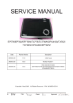
SERVICE MANUAL
HD67
Date
Revise Version
Description
V1.0
Initial Issue
(Separate from ES526_EX536_EX531_CB2800_
EW536_HD66_EX538_HD67 Service Manual V4.0)
2010.06.01
Prepare :
Check:
Approve:
Preface
This manual is applied to HD67 projection system. The manual gives you a brief
description of basic technical information to help in service and maintain the product.
Your customers will appreciate the quick response time when you immediately identify
problems that occur with our products. We expect your customers will appreciate the
service that you offer them.
This manual is for technicians and people who have an electronic background. Please
send the product back to the distributor for repairing and do not attempt to do anything that
is complex or is not mentioned in the troubleshooting.
Notice: The information found in this manual is subject to change without prior notice. Any subsequent changes made to the data herein will be incorporated in future edition.
HD67 Service Manual
Copyright Jun. 2010
All Rights Reserved
Manual Version 1.0
HD67
Confidential
I
Table of Content
Chapter 1
Introduction
Highlight
1-1
Chapter 2 Disassembly Process
Equipment Needed & Product Overview
2-1
Disassemble Top Cover Module
2-2
Disassemble Main Board Module
2-3
Rod Adjustment
2-4
Re-write Lamp Usage Hour
2-5
Chapter 3 Troubleshooting
LED Lighting Message
3-1
Main Procedure
3-2
Chapter 4 Function Test & Alignment Procedure
Service Mode
4-1
Defect specification table
4-1
Test Inspection Procedure
4-2
Factory Fan RPM Reset
4-2
PC MODE
4-3
Video Performance
4-3
Optical Performance Measure
4-4
Chapter 5
Firmware Upgrade
Section 1: System Firmware Upgrade
5-1
Equipment Needed
5-1
HD67
Confidential
III
Firmware Upgrade Procedure
5-2
Section 2: 8051 Firmware Upgrade Procedure
5-3
Equipment Needed
5-3
USB Driver Upgrade Procedure
5-4
8051 Firmware Upgrade Prodedure
5-4
Chapter 6 EDID Upgrade
EDID Introduction
6-1
Appendix A Exploded Image
I
Appendix B
Serial Number System Definition
I
PCBA Code Definition
II
HD67
Confidential
IV
Chapter 1
Introduction
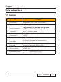
1-1 Highlight
No
Item
Description
1
Power Supply
● Auto-ranging: 100V ~ 240V ± 10%, 50-60Hz
2
Keystone Correction
● +/-16 (Vertical)
3
Power Consumption
●� �����������������
Bright (Normal): ���������
TYP 233W ����
MAX �����
255W ��
@ ������������
110VAC
●�������������
STD(ECO) : ���������
TYP 207W ����
MAX �����
230W ��
@ ������
110VAC
4
Throw ratio
● 1.55~1.7 (Distance/Width)
5
Projection lens
● YM31Z
6
Lamp
●185W Philips E20.9
7
Color Wheel
● 6 Segment; RCBGMY Filter Diameter 40 mm,
3x, 10800 RPM V
8
DMD Chip& Number of
active dots
● “TI”
����� ���������������
DMD 12°, 0.62” �����������������
720P, S450, Dark Chip
����� 3
�
● Number of active dots: 1280(H) x 720(V)
9
System controller
● TI DDP 2431
Altitude&Temperature
● Operating: 0~2,500 ft 5°C~35°C
2,500~5,000 ft 5°C~30°C
5,000~10,000 ft 5°C~25°C
10
HD67
Confidential
1-
Chapter 2
Disassembly Process
2-1 Equipment Needed & Product Overview
1. Screw Bit (+): 105
2. Screw Bit (+): 107
3. Screw Bit (-): 107
4. Hex Sleeves 5 mm
5. Tweezers
6. Projector
* Before you start: This process is protective level II. Operators should wear electrostatic chains.
* Note: - If you need to replace the main board, you have to record the lamp usage hour.
HD67
Confidential
2-
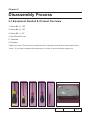
2-1 Disassemble Top Cover
Module
1. Unscrew 2 screws (as red circle) from the
Bottom Cover.
2. Unscrew 2 screws (as green circle) from
the IO Cover .
3. Remove the Top Cover Module.
Note: - When you remove the Top Cover, take care of the connector (as yellow square) which connected Main Board
and Keypad Board Module, then unplug it from Keypad Board Module.
- Avoid damaging by pulling keypad FPC cable.
- Make sure the FPC cable plug into the correct ports when assembling it.
HD67
Confidential
2-
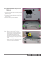
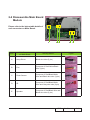
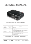
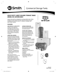
2-2 Disassemble Main Board
Module
Please refer to the below table details of
each connector on Main Board.
E
Male Connector
on Main Board
Item
D C
The key feature
B
A
Figure
A
Lamp Driver
Black wire tube (5 pin)
B
Fan
Compose of Red/Yellow/Black
Wire (3 pin)
C
Photo Sensor
Compose of Red/Black/White
Wire and Black wire tube (3 pin)
D
IR
Compose of Red/Black/White
Wire and Gray wire tube (3 pin)
E
Speaker
Compose of Red/Black Wire and
Black wire tube (2 pin)
HD67
Confidential
2-
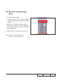
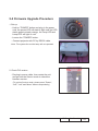
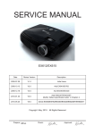
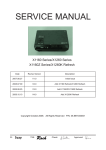
2-3 Rod Adjustment
1. Environment Adjustment
- The distance between the engine and
the screen is 2.4 M.
2
1
- This process should be done at a dark
environment (under 2 Lux).
2. Procedure Adjustment
- Change
the screen to "white screen".
- Adjust the screws by using the rod
on the engine module to readjust the
image.
("screw 1" should be adjusted first, and then "screw 2". Adjust until the yellowish
or bluish parts disappeared.)
Z type driver
3. Abnormal image inspection
- It should not have any abnormal color
at the rim of the image by estimating
through the eyes.
Note: - To avoid over adjusting the rod.
- After the opreation, please use the glue
to fix the screws.
HD67
Confidential
2-
2-4 Re-write Lamp Usage
Hour
1. Get into service mode
- Press "Power", "Left", "Left" and "Menu" buttons sequentially to get into service mode.
2. Use "up" or "down" buttons to select "Exit", then use "left" or "right" buttons to
re-write the lamp hour back to previous lamp usage hour.
3. Press "Enter" to exit the service mode.
Note: left key = decrease lamp hour
right key =increase lamp hour
HD67
Confidential
2-
Chapter 3
Trobleshooting
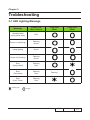
3-1 LED Lighting Message
Message
Power LED
(Red / Green)
Standby State
(input power cord)
Red
Power on (warming)
Flashing
Green
Lamp lighting
Green
Power off (Cooling)
Flashing
Green
Error
(Lamp failed)
Flashing
Red
Error
(Fan failed)
Flashing
Red
Error
(Over Temp.)
Flashing
Red
Steady light
Temp LED
(Red)
Lamp LED
(Red)
Flashing
No light
HD67
Confidential
3-
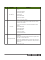
3-2 Main Procedure
The other troubleshooting procedures please refer to common service manual
3-1.
No
Symptom
Procedure
- Ensure the Power Cord and AC Power Outlet are securely
connected
- Check Lamp Cover , Interrupt Switch
1
No Power
- Ensure all connectors are securely connected and aren’t
broken
- Check LVPS
- Check Lamp Driver
- Check Main Board
- Check LED Status
a. Lamp
�����������
Fail: ����������������������������������������������
Power LED (flashes red), Lamp LED (lights red)
- Check Lamp
- Check Lamp Driver
- Check Main Board
2
Auto Shut Down
b. Over
������������
Temp.: ����������������������������������������������
Power LED (�����������������������������������
flashes red)�����������������������
, Temp LED (lights red)
- Check Fan
- Check Main Board
c. Fan
����������
Fail: ������������������������������������������������
Power LED (�������������������������������������
flashes red)�������������������������
, Temp LED (Flashes red)
- Check Fan
- Check Main Board
HD67
Confidential
3-
No
Symptom
Procedure
- Ensure all connectors are securely connected and aren’t
broken
- Check Lamp Module
- Check Lamp Driver
3
No Light On
- Check LVPS
- Check Main Board
- Check Color Wheel
- Check Photo Sensor Board
- Ensure the Signal Cable and Source work
(If you connect multiple sources at the same time, use the
“Source” button switch)
- Ensure all connectors are securely connected and aren’t
broken
4
No Image
- Check Main Board
- Check DMD Board
- Check DMD Chip
- Check Color Wheel
- Check Engine Module
- Ensure the using 3D glasses is good and you must face the
projection.
- Ensure the CD in DVD is HQFS format or the graphic card
from PC can support 3D format.
5
3D Image Abnormal
- Ensure your standing distance is less than 6m from screen.
- Ensure the 3D function is on and execute “3D sync invert” in
OSD menu.
- Check main board.
HD67
Confidential
3-
Chapter 4
Function Test & Alignment Procedure
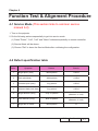
4-1 Service Mode (This section links to common service
manual 4-2)
1. Turn on the projector
2. Do the following actions sequentially to get into service mode
(1) Press "Power", "Left", "Left" and "Menu" buttons sequentially on remote controller.
(2) Service Mode will be shown.
(3) Choose "Exit" to leave the Service Mode after confirming the configuration.
4-2 Defect specification table
Order
Symptom
Pattern
Criteria
1
Bright pixel ( dots)
Black pattern
A+B=0
2
Dark pixel(dots)
White pattern
A+B≤4
3
Unstable pixel (dots)
Any pattern
A+B=0
4
Adjacent dark pixel (dots)
Any pattern
A+B=0
5
Bright blemish (Dirty)
Gray 10 pattern
A+B≤4
(diameter <1 inch)
6
Dark blemish (Dirty)
Blue 60 pattern
A+B≤4
(diameter <1 inch)
7
Bright dot on frame
Black pattern
≤1
HD67
Confidential
4-
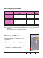
4-3 Test Inspection Procedure
Change parts
Update
Main
Board
Firmware
Version Update
v
v
Color Wheel Index
v
Color
Wheel
Lamp
Module
Blower
v
Reset lamp hour
v
OSD Reset
v
EDID
v
Re-write Lamp Hour
Usage
v
v
Rod adjustment
Fan Factory Reset
Engine
Module
v
v
v
v
Note: - If Color appears abnormal after changing Main Board Module, please do Color Wheel index adjustment.
- After changing parts, check the information above table.
4-4 Factory Fan RPM Reset
After replace main board, Fan, upgrade system FW,
it’s necessary to do:
1. Plug in the power cord, power on the projector, when the
“logo” disappear, press “Power”, “Left”, “Left” and “right”
button in sequence.
2. After about 70 seconds, you can check the fan RPM :
a. Please get into Service Mode (Refer to 4-2)
HD67
Confidential
4-
b. To select “RD MENU”, then press “OK”, Fan detail
information will be shown.
Note: After about 70 seconds,If the blower speed(>70 sec) is
not between 2800-3200,you must change fan.
4-5 PC MODE
Note: - Test signal: analog 1280 x 720 @60Hz
- Connect VGA IN port of Projector with VGA port of Chroma and connect VGA Out port of Projector with VGA port of Monitor by VGA cable, check if the Projected image
and the LCD image are the same.
4-6 Video Performance
1. 3D Test
Procedure - Test equipment: 1.DVD Player&HQFS format CD
Inspection item - 3D test
Or 2.PC with 3D Graphic card
Inspection Distance - < 6M
Criteria - The image should not appear noise, flicker, shadow,
shocking, abnormal color.
HD67
Confidential
4-
4-7 Optical Performance Measure
Inspection Condition
- Environment luminance: 2 Lux
- Product must be warmed up for 3 minutes
- Distances from the screen: 2.4 M
- Screen Size: 60 inches diagonal
1. Test equipment
Procedure - Connect VGA IN port of HD67 with VGA port of Chroma by VGA cable, press "Menu" button, get into OSD mode, the settings are as below:
- "Display mode" is "Presentation", "Brightness" is "50", "Contrast" is "60", and the "Format" is "4:3".
- Please do the Optical Performance Measure.
2. Brightness
Criteria
● 1000 ANSI lumen
3. Full On/Full Off Contrast
Criteria
● 1800:1
4. Uniformity�
Criteria
● 65%
HD67
Confidential
4-
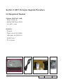
Chapter 5
Firmware Upgrade
Section 1: System Firmware Upgrade (This section links to
common service manual 5-2)
5-1 Equipment Needed
Software: (DDP 2431)
- DLP Composer Lite 9.2
- Firmware
- Library file (Library 9.2)
Hardware:
- Projector
- Power cord: 42.50115G001
- RS232 cable: 42.83618G001
- PC or Laptop
HD67
Confidential
5-
5-2 Firmware Upgrade Procedure
1. Set-up
-H
old on "POWER" button and plug in the power
cord, the power LED will start to flash until the LED
status goes to steady orange, the Temp LED and
Lamp LED will light on red.
- Loosen the "POWER" button.
- Connect projector with PC by RS232 cable.
Note: T
he system fan and the lamp will not operated.
2. Check FW version. - Re-plug in power cable, then restart the unit and get into the Service mode to check the
firmware version.
( To get into Service mode, please press "Power",
"Left", "Left" and "Menu" buttons sequentially.)
HD67
Confidential
5-
Section 2: 8051 Firmware Upgrade Procedure
5-3 Equipment Needed
Software: (DDP 2431- USB)
- Setup _NLINK_en
- Manley USB Driver_NLINK
- xxx_8051_xx.hex
Hardware:
- Projector
- Power cord: 42.50115G001
- USB cable: 42.00286G101
- NLINK Fixture
- PC or Laptop
HD67
Confidential
5-
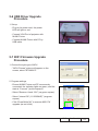
5-6 USB Driver Upgrade Procedure
- Connect VGA Port of projector with NLINK Fixture .
1. Set-up
- Plug in the power cord, the power LED will light on red.
- Connect NLINK Fixture with PC by USB cable.
5-7 8051 Firmware Upgrade Procedure
1. Choose the right type of MCU
- "MCU Choose" picture will appear on the screen, select "N79A901R".
2. Program settings
- Ensure NLlNK Fixture and PC are securely connected: the indicator lights on green, and the state is “Connect” (as blue square).
- Select “Brownout Level 3.8V” (as green square).
- Select “Internel RC (11.0592MHZ)” (as green square).
- Click “Erase/Write(W)” to execute 8051 FW upgrade (as red circle).
HD67
Confidential
5-
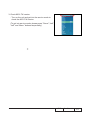
3. Check 8051 FW version
- Turn on the unit and get into the service mode to check the 8051 FW version.
(To get into service mode, please press “Power”,“Left”, “Left” and “Menu” buttons sequentially.)
HD67
Confidential
5-
Chapter 6
EDID Upgrade
6-1 EDID Introduction
- The upgrade procedure for VGA and HDMI ports please refer to common manual chapter 6.
HD67
Confidential
6-
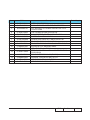
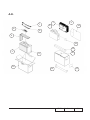
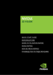
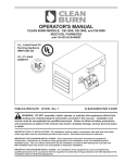
Appendix A (Exploded Image)
Note: This chapter is only designed to show the exploded image of the projector. For updated part numbers, please refer to RSPL report.
D.C. HD67
HD67
Confidential
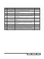
Item
P/N
Description
Parts Supply
1
2
3
70.8FF11G001
70.8FF10G001
70.8FF09G001
SP.8EH01GC01
70.8EH05G001
70.8GY05G001
70.8GY02G001
85.0A123G050
70.8FF21GR01
35.8GY01G001
85.1A323G080
41.89Z02G001
85.005AGG308
42.00454G001
51.00001G001
70.8FF14G001
70.8FF12G001
51.8FF01G001
ASST TOP COVER MODULE HD66
ASSY BOTTOM MODULE HD66
ASSY ONE FAN MODULE EW536
LAMP MODULE FOR PROJECTOR ES526/EX536
ASSY LAMP MODULE ES526
ASSY LAMP DRIVER MODULE HD67
ASSY ENGINE MODULE HD67
SCREW P/F MECH M3*5 Ni
ASSY IO COVER MODULE FOR HD66(SERVICE)
LABEL FOR IO COVER HD67
SCREW PAN MECH M3*8 BLACK “GREEN”
HDMI CONNECTOR GASKET L15*W10*H1
SCREW HEX I/O #4-40 H3.5*L8 NI NYLOK
W.A 8P 120mm MB TO LVPS X1160
CABLE TIE PG-YJ-80
ASSY FRONT COVER MODULE HD66
ASSY IO COVER MODULE HD66
MYLAR FOR MB SHIELDING EW536
ASSY LAMP COVER MODULE FOR
HD66(SERVICE)
LAMP COVER PC MN3600H HD66
MB SHIELDING AIR THIGHT JK-1105 PDG-DSU30
SCREW PAN MECH M2.6*6 Ni NYLOK
MAIN BD SHIELDING SECC 0.6T EW536
TOP SHIELDING SECC 0.4T PDG-DSU30
LOCK SCREW PAN MECH M3*8.5-3.5
BLACK(1018+HEAT TREATMENT)
PCBA MAIN BD FOR HD67 [PROJECTOR]
SCREW PAN MECH M3*6 NI
COLOR WHEEL MYLAR PDG-DSU30
ASSY LVPS MODULE EW536
V
4
5
6
7
8
9
10
11
12
13
14
15
16
70.8FF22GR01
17
18
19
20
21
51.8CS05G021
52.8CS05G002
85.1A526G060
61.8CS05G021
61.8CS04G001
22
61.00018G003
23
24
25
26
80.8GY01G001
85.1A123G060
51.8CS19G001
70.8FF07G001
HD67
Confidential
V
V
V
V
V
V
V
II
ASSY TOP COVER MODULE
HD67
Confidential
III
Item
P/N
1
2
51.8EH09G001
80.8EH03G001
3
42.00304G101
4
5
6
7
8
9
10
11
51.8CS13G001
75.8EH01G031
85.1A123G050
85.3A126G040
51.8CS08G012
51.8CS08G001
51.8EH05G011
51.8EH06G031
12
51.8CS17G002
13
14
15
16
41.89S18G001
52.88N23G001
51.8EH11G001
51.8EH04G031
Description
Parts Supply
METAL DOME ES526
PCBA KEYPAD BOARD FOR Z15 GENERIC
FFC KEYPAD TO FORMATTER BD 16P P=0.5
122mm 1209S
TOP COVER MYLAR PDG-DSU30
BUY ASST TOP COVER MODULE HD66
SCREW PAN MECH M3*5 Ni
SCREW CAP HEAD D7.0 MECH M2.6*4 Ni
ZOOM RING PC MN3600H HD66
ZOOM RING PC MN3600H BLACK PDG-DSU30
ENTER KEY PC MN3600H HD66
LED LENS PC-121 ES526
TEFLON MYLAR 8mm*74mm 0.2t ZOOM RING
PDG-DSU30
EMI GASKET W7*H4*L20 (BLACK)
SPONGE FOR ENTER KEY EP721
KEYPAD BOARD MYLAR ES526
KEYPAD PC MN3600H HD66
HD67
Confidential
V
V
IV
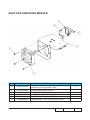
ASSY FAN SHIELDING MODULE
Item
P/N
1
49.8CP02G002
2
3
4
5
6
85.1A123G060
61.8EH01G001
85.1F123G260
61.8EH03G001
51.8EH08G001
Description
Parts Supply
SUNON 70*70*20mm AXIAL FAN, KDE1207PKV1.
MS.B3001.AF.GN, SHRINK TUBE
SCREW PAN MECH M3*6 NI
SCREW PAN MECH M3*6 NI
SCREW PAN MECH E/SF M3*26 Ni
ONE FAN DUCT AL ALLOY ES526
ONE FAN DUCT CAP PPS+GF40% ES526
HD67
Confidential
V
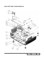
ASSY BOTTOM COVER MODULE
HD67
Confidential
VI
Item
P/N
1
2
3
4
5
6
7
8
9
51.8EH05G001
75.8AA04G001
51.8CS02G021
51.8EH10G001
51.8CS15G001
61.88T19G001
61.8CS03G012
85.1A123G060
85.1A626G050
10
85.1C224G051
11
49.8CQ01G001
12
51.89W18G001
13
51.89W17G001
14
15
16
17
18
19
52.86801G001
86.00122G020
52.89W04G002
51.8CS18G001
41.8EH01G001
41.88T01G001
Description
Parts Supply
ENTER KEY PC MN3600H ES526
BUY ASSY INTERLOCK SWITCH 1409X
BOTTOM COVER PC MN3600H HD66
LVPS MYLAR ES526
K-LOCK MYLAR PDG-DSU30
AC INLET BRACKET FOR X1160E
BOTTOM SHIELDING SECC 0.6T EW536
SCREW PAN MECH M3*6 NI
SCREW PAN MECH M2.6*5 BLACK NYLOK
SCREW PAN MECH M4*5 COLOR W/TOOTH
WASHER Cr3+
SPEAKER 2W 16OHM DAB128 90mm X1261
LIMIT SWITCH HOLDER PC MN3600H BLACK
TDP-SP1
SPEAKER HOLDER PC MN3600H BLACK TDPSP1
RUBBER FOOT REAR DP725
YH-NUT-M2.0*2.0*4.0
SPEAKER HOLDER PORON L-32 TDP-SP1
FRONT MYLAR PDG-DSU30
EMI GASKET W6*L6*H10
EMI L85*W20
HD67
Confidential
V
V
V
VII
ASSY ENGINE MODULE
HD67
Confidential
VIII
Item
P/N
Description
Parts Supply
70.8GY01GR01
ASSY ENGINE MODULE FOR HD67(SERVICE)
YO YM31Z 1.1X P-LENS CHANG UV TO RETAINER
ASSY RELAY MODULE M410HD
YO CONDENSER 1 FOR A15W
SCREW PAN MECH M2.6*6 Ni NYLOK
PCBA DMD BOARD FOR ES526
ASSY ROD MODULE FOR HD67(SERVICE)
ASSY ROD MODULE HD67
ASSY ENGINE BOTTOM COVER Z15
DMD 1280X720 PIXEL .62” 720P 2xLVDS TypeS450 “TI”
DMD RUBBER X1161
DMD BOARD RUBBER X1161
STEP SCREW FOR TYPEX DMD
M2.6*11.8mm,X15
S450 0.55” XGA/SVGA DMD thermal pad, FUJIPOLY, Sarcon XR-HE, 18.4x12.5x0.5 mm
ASSY ENGINE BASE EW536
DMD HEATSINK AL-ALLOY Z15 X1161
ASSY COLOR WHEEL MODULE HD67
CONDENSER LIGHT STOP EX615
YO CONDENSER 2 FOR A15W
ROD COVER FOR EW536
ROD SPRING SUS301,X15
FOCUS RING PC MN3600H HD66
SCREW TAP FLAT HEAD M1.7*3.5 Zn
DUSTPROOF MYLAR FOR FOCUS RING PDGDSU30
EMI GASKET W13*H6*L35
SCREW BINDING MECH M2.6*6 Ni NYLOK
SCREW PAN MECH M2.6*5 Ni NYLOK
V
1
23.8ER01G002
2
3
4
5
6
7
70.8FP08G001
23.8AH20G011
85.1A526G060
80.8EH02G001
70.8GY04GR01
70.8GY04G001
70.8CP10G001
8
48.8ER01G001
9
10
52.8CP01G001
52.8CP02G001
11
85.4A826G118
12
52.8CP04G001
13
14
15
16
17
18
19
20
21
70.8FF08G001
61.8CP02H002
70.8GY03G001
61.8EF03G001
23.8AH20G012
61.8FF01G001
61.88N12G001
51.8CS07G011
85.WA321G035
22
51.8CS20G001
23
24
25
41.87Y03G001
85.5A526G060
85.1A526G050
HD67
Confidential
V
V
V
IX
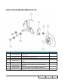
ASSY COLOR WHEEL MODULE Z15
Item
P/N
70.8GY02GR01
1
2
61.8CP03G001
80.8EG04G002
3
23.8GY19G011
4
85.1A126G040
5
51.82Y29G001
6
7
52.83615G011
61.83628G001
Description
Parts Supply
ASSY COLOR WHEEL MODULE FOR HD67
(SERVICE)
CW BRACKET SECC X1161
PCBA PHOTO SENSOR BOARD FOR HD20
YO CW R100C23B72G90M30Y45_URD20VA MOTOR
SCREW PAN MECH M2.6*4 Ni
TAPE 3M J350 10*5mm FOR COLOR WHEEL
DP715
COLOR WHEEL DISC RUBBER 3.8MM CPC
COLOR WHEEL SHOULDER SCREW,EzPro755
HD67
Confidential
V
A.K.
7
9
2
1
14
5
8
6
15
13
3
12
4
10
13
11
HD67
Confidential
XI
Item
P/N
Description
Parts Supply
1
2
DC.8GY01G001
75.8CS02G011
3
56.8EH03G001
4
5
55.8EH02G001
53.8EH01G001
6
56.8EH04G001
7
42.00200G002
8
42.00120G001
9
45.8FF01G002
10
55.8EH01G001
11
12
13
14
15
35.52302G091
35.00040G001
51.0000AG011
51.52109G005
57.00001G001
D.C. HD67
BUY ASSY LENS CAP MODULE HD66
PACKING BOTTOM AIR BAG 440*600 W/CARRY
BAG ES526
PARTITION PAPER ES526
SOFT CARRY BAG ES526
PACKING TOP AIR BAG 240*900MM W/CARRY
BAG ES526
CABLE VGA 15P 1.8M BLK EP739
CABLE POWER CORD 1.8M SP-023/IS-14 EUROPE
INFRARED REMOTE CONTROL HD66 (white)
CARTON AB FLUTE 18KG 395*165*314MM
ES526
LABEL CARTON 108*92 BLANK
LABEL 30mm,GREEN
PACKING TAPE 72MM FOR OPTOMA
PE BAG 450*350*0.07 FOR OPTOMA EP720
PACK SIO2 DRIER 20g
HD67
Confidential
V
V
V
XII
Appendix B
I. Serial Number System Definition
Serial Number Format for Projector (take ES526 as example)
Q
8GY
0
06
1
2
3
4
AAAAA
5
C 0001
6
7
1
:
Q = Optoma
2
:
8GY = Project Code
3
:
0 = Last number of the manufacture year (ex:2010 = 0)
4
:
06 = week of the manufacture year (ex:the sixth week of the year = 06)
5
:
AAAAA = not-defined
6
:
C = Manufacture factory
7
:
0001 = Serial Code
EX: Q8GY006AAAAAC0001
This label "Q8GY006AAAAAC0001" represents the serial number for HD67. It is produced
at CPC on sixth of 2010. Its serial code is 0001.
HD67
Confidential
II. PCBA Code Definition
PCBA Code for Projector
A B
1
XXXXXXXXXX
2
3
1
:
ID
2
:
Vendor Code
3
:
P/N
4
:
Revision
5
:
Date Code
6
:
S/N
C
4
XXX 5
EEEE
6
HD67
Confidential
II