1
SERVICE MANUAL
ES529/EX539/EW539
Date
Revise Version
Description
2011.02.12
V1.0
Initial Issue
Prepare :
Mina
Check:
Amy
Approve:
Preface
This manual is applied to ES529/EX539/EW539 projection system. The manual gives
you a brief description of basic technical information to help in service and maintain the
product.
Your customers will appreciate the quick response time when you immediately identify
problems that occur with our products. We expect your customers will appreciate the
service that you offer them.
This manual is for technicians and people who have an electronic background. Please
send the product back to the distributor for repairing and do not attempt to do anything that
is complex or not mentioned in the troubleshooting.
Notice: The information found in this manual is subject to change without prior notice. Any subsequent changes made to the data herein will be incorporated in future edition.
ES529/EX539/EW539 Service Manual
Copyright Feb. 2011
All Rights Reserved
Manual Version 1.0
ES529/EX539/EW539
Confidential
I
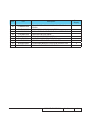
ES529/EX539/EW539 Comparison List
Parts
ES529
EX539
EW539
Engine Module
70.8LH05GR01
70.8LE10GR01
70.8LJ08GR01
DMD
48.8EH01G001
48.8CQ01G003
48.8EJ01G001
Main BD
80.8LH01G001
80.8LE01G001
80.8LJ01G001
IO COVER
70.8LH03GR01
70.8LJ07GR01
TOP COVER
75.8EH01G091
75.8EH01G001
ES529/EX539/EW539
Confidential
Table of Content
Chapter 1
Introduction
Highlight
1-1
Chapter 2 Disassembly Process
Equipment Needed & Product Overview
2-1
Repair notice
2-2
Rod Adjustment
2-3
Re-write Lamp Usage Hour
2-4
Chapter 3
Troubleshooting
LED Lighting Message For Projector
Main Procedure
3-1
3-2
Chapter 4
Function Test & Alignment Procedure
Service Mode Instruction
4-1
Factory Fan RPM Reset
4-1
Test Condition 4-2
Test Inspection Procedure
4-3
PC MODE
4-3
Calibration
4-6
Optical Performance
4-7
Chapter 5 Firmware Upgrade Section 1: System Firmware Upgrade
5-1
5-1
Equipment Needed
III
Get into FW mode
5-2
Check FW version
5-2
Section 2: 8051 FW Upgrade (USB)
5-3
Equipment Needed
5-3
8051 Firmware Upgrade Procedure
5-4
Check 8051 FW version
5-5
Chapter 6
EDID Upgrade
EDID Upgrade Procedure
6-1
Appendix A Exploded Image
I
Appendix B
Serial Number Definition
PCBA Code Definition
ES529/EX539/EW539
I
II
Confidential
IV
Chapter 1
Introduction
1-1 Highlight
No
Item
Description
1
Dimensions (WxDxH)
● 286x192x97mm
2
Power Supply
● 100V-240V±10% 50-60Hz
3
Power Consumption
4
Keystone correction
● +/-40 degree is the scaler spec.
● +/-20 degree is for system angle of V-keystone
5
Throw ratio
● 1.95~2.15 (D/W)(ES529/EX539)
● 1.55~1.7(D/W)(EW539)
Projection lens
● YM09X/FPL62(ES529)
● YM09X/FPL30(EX539)
● YM31Z(EW539)
7
Lamp life
Normal Mode:
● 3000 Hours Standard @ 200W, 50% Survival Rate
ECO Mode:
● 6000 Hours Typical @ 160W, 50% Survival Rate
8
Lamp
● 200W Lamp (Osram E20.8)
9
DMD Chip&Number of
active dots
● 0.55” SVGA, S450, Dark Chip 3(ES529)
0.55” XGA, S450, Dark Chip 3(EX539)
0.65” WXGA, S450, Dark Chip 3(EW539)
● Number of active dots: 800x600 (ES529)
1024x768(EX539)
1280x800(EW539)
10
Color wheel
● 6 segments (R81Y41G84C31W52B71)
11
System controller
● TI DDP 2431
Video compatibility
● NTSC: M/J,3.58MHz, 4.43MHz
● PAL: B, D, G, H, I, M, N, 4.43MHz
● SECAM: B, D, G, K, K1, L,4.25/4.4MHZ
● SDTV: 480i/p, 576i/p
● HDTV: 720p(50/60Hz), 1080i/p(50/60Hz)
6
12
● Normal: TYP 250W Max 275W @110V AC
● ECO: TYP 200W Max 220W @110V AC
● Standby mode < 1W @110V AC
ES529/EX539/EW539
Confidential
1-
No
13
Item
Input signal spec
Description
● VGA-in x1 (support SCART/YPbPr)
● S-Video(Mini DIN) x1
● Audio input(Mini Jack) x1
● Composite Video x1
● HDMI v1.3(with HDCP support)
● Operating: 0~2,500 ft 5°C~35°C
14
Altitude&Temperature
2,500~5,000 ft 5°C~30°C
5,000~10,000 ft 5°C~25°C
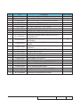
1-2 Compatible Mode
Computer Compatibility
Compatibility
VGA
SVGA
Analog/Digital
V-Sync(Hz)
H-Sync(KHz)
ES529/
EX539
640x350
70
31.5
V
V
640x350
85
37.90
V
V
640x400
70
31.50
V
640x400
85
37.90
V
V
640x480
60
31.5
V
V
640x480
67
-
V
V
640x480
72
37.90
V
V
640x480
75
37.50
V
V
640x480
85
43.30
V
720x350
70
31.50
V
720x400
70
31.50
V
V
720x400
720x576
720x576
800x600
800x600
800x600
800x600
800x600
800x600
800x600
85
50
60
56
60
72
75
80
85
120
37.90
35.20
37.90
48.10
46.90
53.70
-
V
V
V
V
V
V
V
V
V
V
Resolution
ES529/EX539/EW539
EW539
V
V
V
V
V
Confidential
1-
Compatibility
Resolution
Analog/Digital
ES529/
EX539
EW539
V-Sync(Hz)
H-Sync(KHz)
50
60
60
70
72
75
85
120
60
70
75
85
75
50
48.40
56.50
57.70
60.00
68.70
-
V
V
V
V
V
V
V
HD
1024x576
1024x576
1024x768
1024x768
1024x768
1024x768
1024x768
1024x768
1152 × 864
1152 × 864
1152 × 864
1152 × 864
1152 × 870
1280x720
V
V
V
V
V
V
V
V
HD
1280x720
60
45.00
V
V
HD
1280x720
75
-
V
V
HD
1280x720
85
-
V
V
HD
1280x720
120
-
WXGA
1280 x 768
60
47.40
V
WXGA
1280 x 768
70
-
V
WXGA
1280 x 768
75
-
V
WXGA
1280 x 768
85
-
V
WXGA-800
1280 x 800
60
-
V
V
SXGA
1280x1024
60
64.00
V
V
SXGA
1280x1024
75
80.00
V
V
SXGA
1280x1024
85
91.10
V
V
1366x768
60
-
V
1400x900
60
55.94
V
SXGA+
1400x1050
60
-
V
UXGA
1600x1200
60
75.00
1600x1050
60
-
1920x1080
1920x1080
640x480
30
25
66.66
33.80
28.10
XGA
HDTV
HDTV
MAC LC 13’’
ES529/EX539/EW539
V
V
V
V
V
V
V
V
V
V
34.98
V
Confidential
1-
Compatibility
Resolution
V-Sync(Hz)
H-Sync(KHz)
MAC LC13”
640 x 480
66.68
34.98
MAC II 13”
MAC 16”
MAC 19”
640 x 480
832x624
1024X768
66.66
74.55
75
34.98
49.73
60.24
MAC
1152X870
75.06
68.68
MAC G4
640X480
60
31.35
i MAC DV
1024X768
75
60.00
i MAC DV
1152X870
75
68.49
Note: If the Computer Compatibility supportive signal is different from User’s Manual,
please refer to User’s Manual.
ES529/EX539/EW539
Confidential
1-
Chapter 2
Disassembly Process
2-1 Equipment Needed & Product Overview
1. Screw Bit (+): 105
2. Screw Bit (+): 107
3. Screw Bit (-): 107
4. Hex Sleeves: 5 mm
5. Tweezers
6. Projector
* Before you start: This process is protective level II. Operators should wear electrostatic chains.
* Note: - If you need to replace the main board, you have to record the lamp usage hour.
- Some related contents please refer to common SM chapter 2.
ES529/EX529/EW539
Confidential
2-
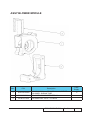
2-2 Repair notice
Disassemble Main Board
Please refer to the below table details of each connector on Main Board.
F
E
D
Item
Male Connector
on Main Board
A
Lamp Driver
B
Fan
Compose of Black/Yellow/Red Wire (3
pin) and green connector
C
Blower
Compose of Red/White/Black Wire (3
pin) and blue wire tube
D
Photo Sensor
E
IR
Compose of Red/Black/White Wire and
Gray wire tube (3 pin)
F
Speaker
Compose of Red/Black Wire and Black
wire tube (2 pin)
The key feature
C
B
A
Figure
Black wire tube (5 pin)
Compose of Red/Black/White Wire (3
pin) and red connector
ES529/EX539/EW539
Confidential
2-
2-3 Rod Adjustment
1. Environment Adjustment
- The distance between the engine and
the screen is 2.4M (ES529/EX539) or
2.0M(EW539).
- This process should be done at a dark
environment (under 10 Lux).
2. Procedure Adjustment
- Change
the screen to "white screen".
- Adjust the screws by using the rod
on the engine module to readjust the
image.
("screw 1" should be adjusted first, and then "screw 2". Adjust until the yellowish
or bluish parts disappeared.)
3. Abnormal image inspection
- It should not have any abnormal color
at the rim of the image by estimating
through the eyes.
2
1
Note: - To avoid over adjusting the rod.
- After the operation, please use the glue
to fix the screws.
ES529/EX539/EW539
Confidential
2-
2-4 Re-write Lamp Usage
Hour
1. Get into service mode
- Press “Power”, “Left”, “Left” and “Menu”
buttons sequentially to get into service
mode.
2.Use “up” or “down” buttons to select “ Exit”,
then use “left” or “right” buttons to re-write
the lamp hour back to previous lamp usage
hour.
Note: left key = decrease lamp hour
right key =increase lamp hour
ES529/EX539/EW539
Confidential
2-
Chapter 3
Trobleshooting
3-1 LED Lighting Message
Standby State
(input power cord)
Power on (warming)
Lamp lighting
Power off (Cooling)
o
o
o
Error
(Over Temp.)
Flashing
Amber
Error
(Fan failed)
Flashing
Amber
Error
(Lamp failed)
Flashing
Amber
Steady light
Power LED
(Green)
Temp LED
(Red)
Lamp LED
(Red)
o
o
o
o
o
o
Flashing
Green
Flashing
Green
o
o
o
o
Power LED
(Amber)
Message
Flashing
o
o
o
o
o
No light
ES529/EX539/EW539
Confidential
3-
3-2 Main Procedure
The other troubleshooting procedures please refer to common service manual
3-1(Main Procedure).
No
Symptom
Procedure
- Check LED Status
a. Lamp
�����������
Fail: ���������������������������
Power LED (flashes amber), Lamp
������������������
LED (lights
red)
- Check Lamp
- Check Lamp Driver
- Check Main Board
1
Auto Shut Down
b. Over
������������
Temp.: ���������������������������
Power LED (����������������
flashes amber)��, ������������������
Temp LED (lights
red)
- Check Fan
- Check Main Board
c. Fan
����������
Fail: ���������������������������
Power LED (����������������
flashes amber)��, ������������������
Temp LED (Flashes
red)
- Check Fan
- Check Main Board
- Ensure the using 3D glasses is good and you must face the
projection.
- Ensure the CD in DVD is HQFS format or the graphic card
from PC can support 3D format.
2
3D Image Abnormal
- Ensure your standing distance is less than 6m from screen.
- Ensure the 3D function is on and execute “3D sync invert” in
OSD menu.
- Check main board.
ES529/EX539/EW539 Confidential
3-
No
Symptom
Procedure
- If you forget the Password, please do the following steps to get
the Universal Password:
(1) When you turn on the projector, the message “Enter
Security Code” appears. Please Input the “Current Security
Code 8642” by Remote Control,
(2) Press “Menu” button, select “Setup”, “Change Password”,
then press” Enter” button. The message “Enter Security
Code” appears again, repeat step (1).
(3) The message “Enter New Security Code” appears. Input a
4-digits code (letters and/or numbers) that you define.
(4) To confirm, key in the password again. The “Security Code
change successfully” appear on the screen.
3
Forgetting Password
(administrator
Password)
(1)
(2)
(3)
ES529/EX539/EW539
Confidential
3-
Chapter 4
Function Test & Alignment Procedure
4-1 Service Mode Instruction (This section
links to common service manual 4-2 Service
Mode)
1. Turn on the projector.
2. Press Power --> Left --> Left --> Menu on Keypad or Remote
controller.
3. Service mode will be shown. After confirming the configuration,
press "Exit" to exit.
4-2 Factory Fan RPM Reset
After replace main board,blower or upgrade system FW, you need to
do:
1. Plug in the power cord, hold on “Menu” button then press
“Power” button, when the power LED lighted orange, Temp
LED and Lamp LED lighted red about one second, loosen
“Menu” button.
2. After several minutes, you can check the fan RPM as red circle
a. Please get into Service Mode.
b. Select “RD menu”, then press “Enter”, Fan detail information
will be shown.
Note: If the factory fan Value doesn’t show in service mode,please
repeat the step 1,2 again.
ES529/EX529/EW539 Confidential
4-
4-3 Test Condition(�����������������������������
This section links to common
service manual 4-4 Test Condition)
Defect specification table
For ES529/EX539
Order
Symptom
Pattern
Criteria
Gray10 pattern
A+B=0
White pattern
A+B≤4
1
Bright pixel ( dots)
2
Dark pixel(dots)
3
Unstable pixel (dots)
Any pattern
A+B=0
4
Adjacent dark pixel (dots)
Any pattern
A+B=0
5
Dark blemish (Dirty)
Blue 60 pattern
A+B≤2
(diameter <1/2 inch)
6
Bright blemish (Dirty)
Gray10 pattern
A+B≤2
(diameter <1/2 inch)
7
Bright dots on frame
Gray10 pattern
≤1
Pattern
Criteria
Gray 10 pattern
A+B=0
White pattern
A+B≤7
For EW539
Order
Symptom
1
Bright pixel ( dots)
2
Dark pixel(dots)
3
Unstable pixel (dots)
Any pattern
A+B=0
4
Adjacent dark pixel (dots)
Any pattern
A+B=0
5
Dark blemish (Dirty)
Blue 60 pattern
A+B≤4
(diameter <1 inch)
6
Bright blemish (Dirty)
Gray 10 pattern
A+B≤4
(diameter <1 inch)
7
Bright dots on frame
Gray 10 pattern
≤1
ES529/EX539/EW539
Confidential
4-
4-4 Test Inspection Procedure
Update
Main
Board
FW
Version Update
V
V
Color Wheel Index
V
Change Parts
Color
Lamp
Engine
wheel module module
V
Lamp reset
V
ADC Calibration
V
V
OSD Reset
V
V
Re-write Lamp Hour
Usage
V
EDID
V
ROD Adjustment
Factory Fan RPM
Reset
Rod
Blower
module
V
V
V
V
V
4-5 PC MODE
Note:EX539 the native resolution of test signal is 1024x768@60HZ.
ES529 the native resolution of test signal is 800x600@60HZ.
EW539 the native resolution of test signal is 1280x800@60HZ.
We take EX539 for example here.
The other contents please refer to common service manual 4-6 PC MODE.
ES529/EX539/EW539
Confidential
4-
1.Bright pixel
Procedure - Test equipment: video generator.
Inspection item
Criteria
- Test signal: analog 1024x768@60Hz.
- Test Pattern: Gray10 pattern
- Bright pixel check.
- Bright pixel is unacceptable under gray10 pattern
Please refer to the figure in 4-4 Test Condition
for Frame and Active area.
Note: The defect criteria follows TI specification.
Gray 10
2. Dark pixel
Procedure - Test equipment: video generator.
- Test signal: analog 1024x768@60Hz.
- Test Pattern: White pattern
Inspection item
- Dark pixels check.
- White pattern
- Adjacent dark pixel.
White
- The number of the dark pixels should be less or
equal to 4 pixels.
- Adjacent pixel with each other is unacceptable.
Note: The defect criteria follows TI specification.
Criteria
ES529/EX539/EW539
Confidential
4-
3. Bright Blemish
Procedure
Inspection item
Criteria
- Test equipment: video generator
- Test signal: 1024x768@60Hz
- Test Pattern: Gray 10
- Bright blemish check
- The bright blemish should be less or
equal to 2 under gray 10 pattern.
- Ref. Defect specification table
Gray 10
4. Dark Blemish
Procedure
Inspection item
Criteria
- Test equipment: video generator
- Test signal: 1024x768@60Hz
- Test Pattern: Blue 60
- Dark blemish check
- The dark blemish should be less or
equal to 2 under blue 60 pattern.
- Ref. Defect specification table
Blue 60
ES529/EX539/EW539
Confidential
4-
4-6 ADC Calibration
Procedure
- Test equipment: video generator
- Once Main Board is changed, PC calibration
should be done as well.
(1) Test signal: analog 1024X768@60Hz
(for EX539)
analog 800X600@60Hz
(for ES529)
analog 1280X800@60Hz
(for EW539)
(2) Test Pattern: White/Black
- Note:
White/Black
(1) Calibration pattern should be in full screen mode.
(2) Please refer to 4-1 Guide to get into service mode,
then get into “RD Menu”,choose“ADC Calibration”.
Inspection item
- Check if there is lines on the screen.
- Check if there is noise on the screen.
- Horizontal and vertical position of the video should be
adjustable to the screen frame.
Criteria
- If there is noise on the screen, the product is considered
as failure product.
- The screen appears normal, it shouldn’t appear any
abnormal condition, such as lines and so on.
- Check if the projection is the same as monitor displayed.
ES529/EX539/EW539
Confidential
4-
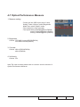
4-7 Optical Performance Measure
1. Measure setting
- Please get into OSD menu,select “Lamp
Setting” under “Options”,select"Brightness
Mode",then select “Bright” mode.
- Test equipment: video generator.
- Test signal:analog 800x600@60Hz (ES529)
analog 1024x768@60Hz (EX539)
analog 1280x800@60Hz (EW539)
2. Brightness
Criteria: 1155 ANSI Lumens(ES529/EX539)
1210 ANSI Lumens(EW539)
3. Contrast
Criteria: 1800:1(ES529/EX539)
1600:1(EW539)
4. Uniformity
Criteria: 70%
Note:The other contents please refer to common service manual 4-8
Optical Performance Measure.
ES529/EX539/EW539
Confidential
4-
Chapter 5
Firmware Upgrade
Section 1: System Firmware Upgrade
5-1-1 Equipment Needed
Software: (DDP2431-RS232)
- DLP Composer Lite V10.0
- Firmware (*.img)
- library (ES529/EX539/EW539 library)
Hardware:
- Projector
- Power Cord (42.50115G001)
- RS232 (42.83618G001)
- PC or Laptop
Note1: we will show the hot key of service mode and how to check FW version,the other contents please refer to common service manual 5-1 .
Note2: During FW upgrade procedure,please select "32KB" in "Skip Boot Loader Area".
ES529/EX539/EW539
Confidential
5-
5-1-2 Get into FW mode
1.Set up
- Hold on "POWER" button and plug in the
power cord, the power LED will start to flash
until the LED status goes to steady orange,
the Temp LED and Lamp LED will light on red.
- Loosen the "POWER" button.
- Connect projector with PC by RS232 cable.
Note: - The system fan and the lamp will not
operate.
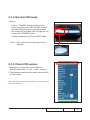
5-1-3 Check FW version
1.Restart the unit and get into the Service Mode(Press Power --> Left --> Left --> Menu).
2.The firmware version will be shown as red circle on the screen.
Note: Another contents please refer to common service
manual 5-Section 1.
ES529/EX539/EW539 Confidential
5-
Section 2: 8051 FW Upgrade
5-2-1 Equipment Needed
Software: (N79A901R-USB)
- Setup _NLINK_en
- Manley USB Driver_NLINK
- xxx_8051_xx.hex
Hardware:
- Projector
- Power cord: 42.50115G001
- USB Cable mini USB to USB (A) (42.00284G001)
- NLINK Fixture
- PC or Laptop
ES529/EX539/EW539 Confidential
5-
5-2-2 8051 Firmware Upgrade
Procedure
1. Set-up
- Plug in the power cord, the power LED will light on red.
- Connect VGA-IN Port of projector with NLINK Fixture.
- Connect NLINK Fixture with PC by USB cable.
2. Execute 8051 FW Program
- Double click “NLINK V1.2” to execute NLINK program.
3. Choose the right type of MCU
- “MCU Choose” picture will appear on the screen, select
“N79A901R”.
- Click “OK”.
4. Program settings
Ensure NLlNK Fixture and PC are securely connected: the
indicator lights on green, and the state is “Connect” (as blue
square).
- Select “Brownout Level 3.8V” (as green square).
- Select “Internel RC(11.0592MHz)” (as green square).
- Click “Erase/Write(W)” to execute 8051 FW upgrade (as
red circle).
Note: Another contents please refer to common service
manual 5-Section 4.
ES529/EX539/EW539 Confidential
5-
5-2-3 Check 8051 FW version
1. Restart the unit and enter the Service Mode (Press
Power --> Left --> Left--> Menu).
2. The firmware version will be shown as red circle on the
screen.
ES529/EX539/EW539 Confidential
5-
Chapter 6
EDID Upgrade
6-1 EDID Upgrade Procedure
- The upgrade procedure for VGA and HDMI ports please refer to common service manual chapter 6.
ES529/EX539/EW539
Confidential
6-
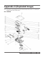
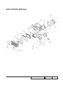
Appendix A (Exploded Image)
Note: This chapter is only designed to show the exploded image of the projector. For updated part numbers, please refer to RSPL report.
D.C. EX539
ES529/EX539/EW539
Confidential
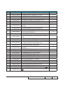
Item
P/N
1
2
3
70.8LE01G001
70.8FE06G001
70.8FE01G001
Parts
Supply
Description
6
7
8
9
10
11
12
13
14
15
16
17
18
70.8LE08G001
42.00455G012
51.8FF01G001
61.8CS05G051
61.8CS04G001
85.0A123G050
85.1A526G060
85.005AGG308
85.1A323G080
35.8LE01G001
85.1A123G060
41.89Z02G001
51.8CS19G001
19
61.00018G003
20
21
22
23
24
25
26
27
28
41.89C06G001
41.89K07G001
52.8EH04G001
70.8FE05G001
61.87340G001
41.83F01G001
51.8CS05G011
70.8FE07G001
41.8AU02G001
ASSY TOP COVER MODULE EX539
FAN SHIELDING MODULE EX538
ASSY BOTTOM MODULE EX538
ASSY IO COVER MODULE FOR
ES529(SERVICE)
ASSY IO COVER MODULE EX539
OSRAM E20.8 200W LAMP MODULE EX539
ASSY OSRAM LAMPDRIVER MODULE 200W
FOR ES529(SERVICE)
ASSY LAMP COVER MODULE FOR
ES526(SERVICE)
ASSY LAMP DRIVER MODULE EX539
W.A. 8P TO 16P 120mm MB TO LVPS 1410X
MYLAR FOR MB SHIELDING EW536
MAIN BD SHIELDING SECC 0.6T EX539
TOP SHIELDING SECC 0.4T PDG-DSU30
SCREW P/F MECH M3*5 Ni
SCREW PAN MECH M2.6*6 Ni NYLOK
SCREW HEX I/O #4-40 H3.5*L8 NI NYLOK
SCREW PAN MECH M3*8 BLACK “GREEN”
IO LABEL PC EX539
SCREW PAN MECH M3*6 NI
HDMI CONNECTOR GASKET L15*W10*H1
COLOR WHEEL MYLAR PDG-DSU30
LOCK SCREW PAN MECH M3*8.5-3.5
BLACK(1018+HEAT TREATMENT)
EMI GASKET L44*H1*W21
EMI GASKET W13*H1*L13 AUDIO
RUBBER 10X5X2.5 ES526
ASSY BLOWER 4520 MODULE FOR EX538
STAND OFF M3*4L D8.0 2100MP
GASKET/(L*13 W*10 H*2)
LAMP COVER PC LN2520 BLACK EX538
ASSY FRONT COVER MODULE EX538
EMI GASKET W6*H1*L6mm
29
51.81540G001
TAPE 3M J350 17*60mm
70.8LH03GR01
4
5
70.8LE02G001
70.8LE05G001
70.8LH04GR01
70.8FM13GR01
ES529/EX539/EW539
Confidential
V
V
V
II
Item
P/N
30
61.8EH02G001
31
32
33
34
35
36
37
38
52.8EH02G002
52.8CS05G002
51.8FM05G001
51.8FM04G001
70.8LE03G001
51.8FM02G001
80.8LE01G001
52.8FF01G001
Parts
Supply
Description
CLAMP FOR LVPS CABLE,PINGOOD WC-6
ES526
SPONGE JK-1105 25X12X3 ES526
MB SHIELDING AIR THIGHT JK-1105 PDG-DSU30
8FM LVPS MYLAR 200W
8FM MYLAR RESIST LIGHT
ASSY ENGINE MODULE EX539
8FM FOIL HT800 FOR LAMP COVER
PCBA MAIN BOARD FOR EX539 PROJECTOR
HDMI LIGHT CUT SPONGE EW536
ES529/EX539/EW539
Confidential
V
III
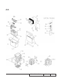
ASSY BLOWER MODULE
Item
P/N
1
49.8CS01G002
2
3
52.82G08G001
52.89T01G001
Parts
Supply
Description
SUNON 45*20mm GB1245PKV1-8AY, F TYPE
BLOWER, SHRINK TUBE
BLOWER 4520 RUBBER EP7190
BLOWER AIR TIGHT F12 H5350
ES529/EX539/EW539
Confidential
V
IV
ASSY TOP COVER MODULE
ES529/EX539/EW539
Confidential
Item
P/N
Description
1
2
51.8EH04G031
80.8EH03G001
3
42.00304G101
4
5
6
7
51.8CS13G001
75.8EH01G091
85.1A123G060
85.3A126G040
8
51.8CS12G002
9
10
51.8CS08G012
51.8EH05G011
11
51.8EH06G061
12
51.8CS17G002
13
14
15
16
41.89S18G001
52.88N23G001
51.8EH11G001
57.83N01G001
KEYPAD PC MN3600H HD66
PCBA KEYPAD BOARD FOR Z15 GENERIC
FFC KEYPAD TO FORMATTER BD 16P P=0.5
122mm 1209S成朋
TOP COVER MYLAR PDG-DSU30
TOP COVER MODULE EX539
SCREW PAN MECH M3*6 NI
SCREW CAP HEAD D7.0 MECH M2.6*4 Ni
ZOOM RING HOLDER PC MN3600H BLACK FOR
PDG-DSU30
ZOOM RING PC MN3600H HD66
ENTER KEY PC MN3600H HD66
4WAY KEY SILVER MN3600H WITH KEYSTONE
LOGO EW539
TEFLON MYLAR 8mm*74mm 0.2t ZOOM RING
PDG-DSU30
EMI GASKET W7*H4*L20 (BLACK)
SPONGE FOR ENTER KEY EP721
KEYPAD BOARD MYLAR ES526
TEFLON FOR PD726W
ES529/EX539/EW539
Parts Supply
Confidential
V
V
VI
ASSY FAN SHIELDING MODULE
Item
P/N
1
49.8CP02G003
2
3
4
5
6
7
8
9
51.88T18G001
61.8AN01G002
61.88T05G051
85.1F123G260
85.1A123G060
52.88T08G001
52.8EH02G002
61.8FM01G001
Description
Parts Supply
SUNON 70*70*20mm AXIAL FAN, SHRINK TUBE,
WIRE LENGTH 155mm
KAPTON 10*10 0.05t X1160
LAMP BLOWER DUCT X15 GENERIC
8FM TWO FAN SHIELDING
SCREW PAN MECH E/SF M3*26 Ni
SCREW PAN MECH M3*6 NI
FAN SHELDING AIR TIGHT F12 X1160
SPONGE JK-1105 25X12X3 ES526
AL FOIL 1 8FM
ES529/EX539/EW539
Confidential
V
VII
ASSY BOTTOM COVER MODULE
ES529/EX539/EW539
Confidential
VIII
Item
P/N
1
2
3
4
5
6
7
8
9
52.8EH05G001
75.8AA04G001
51.8CS02G011
51.8FE01G001
51.8CS15G001
61.88T19G001
61.8CS03H021
85.1A123G060
85.1A626G050
10
85.1C224G051
11
49.8CQ01G001
12
51.89W18G011
13
51.89W17G001
14
15
16
17
18
19
20
21
22
23
24
25
51.8FM01G001
86.00122G020
52.89W04G002
51.8CS18G001
41.8EH01G001
41.89B02G001
75.8FE01GP01
51.8FM03G001
51.8EH12G001
52.8EH06G001
85.1C123G060
85.1C123G080
Description
Parts Supply
RUBBER ADJUST FOOT ES526
BUY ASSY INTERLOCK SWITCH 1409X
BOTTOM COVER PC LN2520 BLACK EX538
LVPS MYLAR EX538
K-LOCK MYLAR PDG-DSU30
AC INLET BRACKET FOR X1160E
8FM BOTTOM SHIELDING 200W
SCREW PAN MECH M3*6 NI
SCREW PAN MECH M2.6*5 BLACK NYLOK
SCREW PAN MECH M4*5 COLOR W/TOOTH
WASHER Cr3+
SPEAKER 2W 8OHM 90mm LB40200083-C198
GP ES526
LIMIT SWITCH HOLDER PC LN2520 BLACK
EX538
SPEAKER HOLDER PC MN3600H BLACK
TDP-SP1
8FM LAMP DRIVER INLET MYLAR
YH-NUT-M2.0*2.0*4.0
SPEAKER HOLDER PORON L-32 TDP-SP1
FRONT MYLAR PDG-DSU30
EMI GASKET W6*L6*H10
EMI TAPE W*20/L*70
ASSY MATRITEK 200W LVPS FOR EX538
8FM LAMP DRIVER INLET MYLAR-2
LVPS GUIDE MYLAR ES526
SILICON RUBBER 18.8x7.6x4.8 ES526
SCREW ISO M3*6mm NI PH W/LW BFA
SCREW ISO M3*8mm NI PH W/LW
ES529/EX539/EW539
Confidential
V
V
V
V
IX
ASSY ENGINE MODULE
ES529/EX539/EW539
Confidential
Item
P/N
Description
Parts Supply
7
51.8CS20G001
8
9
85.1A526G060
61.8CP02H002
ASSY ENGINE MODULE FOR EX538 (SERVICE)
SCREW TAP FLAT HEAD M1.7*3.5 Ni
SCREW BINDING MECH M2.6*6 Ni NYLOK
SCREW PAN MECH M2.6*5 Ni NYLOK
SPRING FOR DMD STEP SCREW X1161
FOCUS RING PC MN3600H HD66
DMD PORON Z15/X15Z ENGINE
DUSTPROOF MYLAR FOR FOCUS RING PDGDSU30
SCREW PAN MECH M2.6*6 Ni NYLOK
DMD HEATSINK AL-ALLOY Z15 X1161
ASSY COLOR WHEEL MODULE
BS275,BX275(SERVICE)
ASSY 6S COLOR WHEEL MODULE Z15 EX539
ASSY ROD MODULE FOR ES526/EX536 (SERVICE)
ASSY ROD MODULE EX539
ASSY ENGINE BASE Z15 EX539
S450 0.55” XGA/SVGA DMD thermal pad, FUJIPOLY, Sarcon XR-HE, 18.4x12.5x0.5 mm
PCBA DMD BOARD FOR ES526
0.55” XGA 2xLVDS SERIES 450 DMD -8 1076603cB TI
DMD RUBBER X1161
ASSY RELAY MODULE EX538
CONDENSER LIGHT STOP EX615
YO CONDENSER 1 FOR A15W
YO CONDENSER 2 FOR A15W
ROD SPRING SUS301 3/4H,X15
ROD COVER NEW 0.5T AL5052
3M TAPE FOR DSU30
ASSY ENGINE MODULE FOR ES529 (SERVICE)
ASSY ENGINE BOTTOM COVER Z15
STEP SCREW FOR DMD M2.6*16.2mm X1161
EMI GASKET W13*H6*L35
YO PROJECTION LENS YM09X FOR X15_氟素
油
V
1
2
3
4
5
6
70.8FE12GR01
85.WA121G035
85.5A526G060
85.1A526G050
61.8CP15H001
51.8CS07G011
52.8CP22G001
70.8HC09GR01
10
70.8LE06G001
70.8EH18GR01
11
12
70.8LE04G001
70.8LE07G001
13
52.8CP04G001
14
80.8EH02G001
15
48.8CQ01G003
16
17
18
19
20
21
22
23
24
25
26
52.8CP01G001
70.8FE12G001
61.8EF03G001
23.8AH20G011
23.8AH20G012
61.88N12G021
61.8FE02G001
51.8CS30G001
70.8LE10GR01
70.8CP10G001
61.8CP16H001
41.87Y03G001
27
23.88N01G001
ES529/EX539/EW539
Confidential
V
V
V
V
V
XI
ASSY COLOR WHEEL MODULE Z15
Item
P/N
70.8FB23GR01
1
2
61.8CP03G001
80.8EG04G002
3
23.8FB19G001
4
85.1A126G040
5
51.82Y29G001
6
7
52.83615G001
61.83628G001
Description
Parts Supply
ASSY COLOR WHEEL MODULE EX762 (SERVICE)
CW BRACKET SECC X1161
PCBA PHOTO SENSOR BOARD FOR HD20
YO 5S R76Y32G78W98B76 CW_URD20 MOTOR_
TIM CHANGED TO W/B IN B
SCREW PAN MECH M2.6*4 Ni
TAPE 3M J350 10*5mm FOR COLOR WHEEL
DP715
COLOR WHEEL DISC RUBBER, EzPro755
COLOR WHEEL SHOULDER SCREW
ES529/EX539/EW539
Confidential
V
V
XII
A.K.
ES529/EX539/EW539
Confidential
XIII
Parts
Supply
Item
P/N
Description
1
2
35.00040G001
35.52302G091
3
35.80N05G001
4
35.86301G001
SPEC LABEL BLANK PD120
5
35.8EG02G001
LAMP COVER USE LABEL
6
51.00070GC01
PE STRETCH FILM 500MM*1500M*0.02MM
GREEN FOR CPC
7
51.52109G005
PE BAG 450*350*0.07 FOR OPTOMA EP720
8
9
10
55.59901G001
55.80S06G001
55.80S10G001
11
55.8EH01G001
12
13
55.8EH02G001
57.00001G001
14
58.54603G002
15
16
17
18
19
20
21
22
23
24
25
75.8CS02G001
55.83R03G002
75.8EH13G001
56.8EH01G001
56.8EH02G001
51.00037G001
35.82001G111
51.00069G001
51.0000AG011
DC.8LE01G001
42.00200G002
26
45.8JA01G001
27
46.80S01G101
CORNER BOARD 40*40*5*900mm GREEN
PAPER CORNER 50*50*1230mm TDP-T90
PAPER COVER 1180*980mm TDP-T91
CARTON AB FLUTE 18KG 395*165*314MM
ES526
PARTITION PAPER ES526
PACK SIO2 DRIER 20g
NEW WOOD PALLET120*100*13cm (DOUBLE
FACE) FOR COMPAQ
LENS CAP MODULE ES526
L TYPE PAPER 1190x1000x1350 EP747
TOP COVER PET MEMBRNE MODULE ES526
PACKING BOTTOM AIR BAG 480*600MM ES526
PACKING TOP AIR BAG 240*1050MM ES526
TRANSPARENT TAPE 2.4cm
AK LABEL 3”*3” BLANK
PACKING STRAP 13.5MM*1500M*0.7MM GREEN
PACKING TAPE 72MM FOR OPTOMA
D.C. 200W XGA EX539
CABLE VGA 15P 1.8M BLK EP739 誠泰
REMOTE CONTROL OF EW535ST/EX545ST
WITHOUT LASER (3D)
BATTERY #7 1.5V NOVACELL
LABEL 30mm,GREEN
LABEL CARTON 108*92 BLANK
PALLET LABEL (W)100mm X(H)53mm FOR OPTOMA MODEL
ES529/EX539/EW539
Confidential
V
V
V
V
XIV
Item
P/N
28
36.00024G001
29
42.50115G001
30
36.8LH01G001
31
36.8LH02G001
32
51.86213G002
33
53.8EH01G001
Parts
Supply
Description
WARRANTY CARD US FOR LPP SERIES, 1
YEAR
CABLE POWER CORD 1.8M SP30+IS14 US
USER’S GUIDE MULTILINGUAL (CD) ES539/
EX539/EW539
QUICK START CARD MULTILINGUAL ES529/
EX529/EW539
PE BAG ZIPPER #9 W/RECYCLING MARK FOR
OPTOMA
SOFT CARRY BAG ES526
ES529/EX539/EW539
Confidential
V
V
V
XV
Appendix B
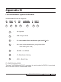
I. Serial Number System Definition
Serial Number Format for Projector
Q
8LE
1
2
0
3
09
AAAAA
4
C 0001
5
6
7
1
:
Q = Optoma
2
:
8LE = Project Code
3
:
0 = Last number of the manufacture year (ex:2010 = 0)
4
:
09 = week of the manufacture year (ex:the ninth
week of the year = 09)
5
:
AAAAA = not-defined
6
:
C = Manufacture factory
7
:
0001 = Serial Code
EX: Q8LE009AAAAAC0001
This label "Q8LE009AAAAAC0001" represents the serial number for EX539. It is produced
at CPC on ninth of 2010. Its serial code is 0001.
ES529/EW539/EX539
Confidential
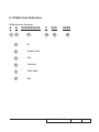
II. PCBA Code Definition
PCBA Code for Projector
A B
1
XXXXXXXXXX
2
3
1
:
ID
2
:
Vendor Code
3
:
P/N
4
:
Revision
5
:
Date Code
6
:
S/N
C
4
XXX 5
EEEE
6
ES529/EX539/EW539
Confidential
II