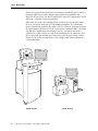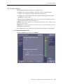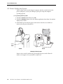
1
R2 DX/LS
™
User Manual
Software Versions 8.6–8.7
PN MAN-01043 Rev 001
Screen-Film Mammography
R2™ DX / LS User Manual
Software Versions 8.6–8.7
PN MAN-01043 Rev 001
Technical Support
For support in North America contact:
Toll Free: +1 866.243.2533 (866.CHECKED)
Email: [email protected]
Hours: Monday – Friday, 6:00 AM – 5:00 PM, PT (GMT –8:00)
Website: www.hologic.com
For support in Europe, South America, or Asia, contact your local dealer or distributor.
© 2008, Hologic, Inc. All rights reserved. Duplication or distribution without written permission
is prohibited. Hologic reserves the right to revise this manual. Issued August 2008.
Protected by one or more of the following U.S. Patents: 5133020, 5452367, 5491627, 5537485,
5622171, 5657362, 5673332, 5729620, 5732697, 5740268, 5815591, 5828774, 5832103,
5917929, 6014452, 6035056, 6075879, 6078680, 6185320, 6198838, 6263092, 6266435,
6301378, 6404908, 6434262, 6477262, 6574357, 6580818, 6640001, 6628815, 6909795,
7054473, 7072498, 7146031, 7174515
Hologic, the Hologic logo, CheckMate, DigitalNow, Earlier. Smarter. Better, EmphaSize,
GreenLight, ImageChecker, Malc, PeerView, RightOn, R2, and the R2 Logo are trademarks or
registered trademarks of Hologic, Inc. in the USA. Microsoft, and Windows are registered
trademarks of Microsoft Corporation. MergeCOM-3 is a trademark of Merge Healthcare.
Hologic Inc.
35 Crosby Drive
Bedford, MA 01730-1401 USA
Tel: +1.781.999.7300
Sales: +1.781.999.7453
Fax: +1.781.280.0668
Hologic N.V.
Authorized Representative
Leuvensesteenweg 250A
1800 Vilvoorde, Belgium
Tel: +32.2.711.4680
Fax: +32.2.725.2087
Asia Pacific
Room 302, Hung Kei Building
5-8 Queen Victoria Street
Central, Hong Kong
Tel: +852.3102.9200
MergeCOM-3 Advanced Integrator’s
Tool Kit is a product of Merge
Healthcare.
ii
R2 DX/LS User Manual – PN MAN-01043 Rev 001
Contents
Part 1: Introduction . . . . . . . . . . . . . . . . . . . . . . . . . . . . . . . . . . . . . . . . . . . . . . . . . . . . . . .
1
1.1. Resources Available . . . . . . . . . . . . . . . . . . . . . . . . . . . . . . . . . . . . . . . . . . . . . . . . . . . 2
1.2. How to Use this Manual . . . . . . . . . . . . . . . . . . . . . . . . . . . . . . . . . . . . . . . . . . . . . . . . 3
Manual Organization . . . . . . . . . . . . . . . . . . . . . . . . . . . . . . . . . . . . . . . . . . . . . . . . . . 3
Conventions Used in this Manual . . . . . . . . . . . . . . . . . . . . . . . . . . . . . . . . . . . . . . . . . 3
1.3. Warnings and Cautions . . . . . . . . . . . . . . . . . . . . . . . . . . . . . . . . . . . . . . . . . . . . . . . . 4
Warnings: System Operation . . . . . . . . . . . . . . . . . . . . . . . . . . . . . . . . . . . . . . . . . . . . .
Warnings: Maintenance . . . . . . . . . . . . . . . . . . . . . . . . . . . . . . . . . . . . . . . . . . . . . . . .
Cautions: System Operation . . . . . . . . . . . . . . . . . . . . . . . . . . . . . . . . . . . . . . . . . . . . .
Cautions: Installation and Maintenance . . . . . . . . . . . . . . . . . . . . . . . . . . . . . . . . . . . .
4
4
5
6
Part 2: Description . . . . . . . . . . . . . . . . . . . . . . . . . . . . . . . . . . . . . . . . . . . . . . . . . . . . . . . .
7
2.1. Overview . . . . . . . . . . . . . . . . . . . . . . . . . . . . . . . . . . . . . . . . . . . . . . . . . . . . . . . . . . . 7
2.2. System Components . . . . . . . . . . . . . . . . . . . . . . . . . . . . . . . . . . . . . . . . . . . . . . . . . 10
2.3. Overview of Operation . . . . . . . . . . . . . . . . . . . . . . . . . . . . . . . . . . . . . . . . . . . . . . . . 12
Studies Screen Overview . . . . . . . . . . . . . . . . . . . . . . . . . . . . . . . . . . . . . . . . . . . . . . .
Scanning and Processing . . . . . . . . . . . . . . . . . . . . . . . . . . . . . . . . . . . . . . . . . . . . . . .
System Alerts . . . . . . . . . . . . . . . . . . . . . . . . . . . . . . . . . . . . . . . . . . . . . . . . . . . . . . . .
Controls Screen . . . . . . . . . . . . . . . . . . . . . . . . . . . . . . . . . . . . . . . . . . . . . . . . . . . . . .
12
14
15
17
2.4. Licensed Features . . . . . . . . . . . . . . . . . . . . . . . . . . . . . . . . . . . . . . . . . . . . . . . . . . . . 18
DigitalNow DICOM Export . . . . . . . . . . . . . . . . . . . . . . . . . . . . . . . . . . . . . . . . . . . . 18
ImageChecker Screen-Film CAD . . . . . . . . . . . . . . . . . . . . . . . . . . . . . . . . . . . . . . . . . 18
2.5. Other Features . . . . . . . . . . . . . . . . . . . . . . . . . . . . . . . . . . . . . . . . . . . . . . . . . . . . . . 19
2.6. System Inputs and Outputs . . . . . . . . . . . . . . . . . . . . . . . . . . . . . . . . . . . . . . . . . . . . 20
Supported Views . . . . . . . . . . . . . . . . . . . . . . . . . . . . . . . . . . . . . . . . . . . . . . . . . . . . . 20
View Modifiers . . . . . . . . . . . . . . . . . . . . . . . . . . . . . . . . . . . . . . . . . . . . . . . . . . . . . . 21
Results Output Options . . . . . . . . . . . . . . . . . . . . . . . . . . . . . . . . . . . . . . . . . . . . . . . . 22
Part 3: Studies . . . . . . . . . . . . . . . . . . . . . . . . . . . . . . . . . . . . . . . . . . . . . . . . . . . . . . . . . . .
23
3.1. Working with Films . . . . . . . . . . . . . . . . . . . . . . . . . . . . . . . . . . . . . . . . . . . . . . . . . . 24
Film Requirements . . . . . . . . . . . . . . . . . . . . . . . . . . . . . . . . . . . . . . . . . . . . . . . . . . .
R2-Supported Lead Markers . . . . . . . . . . . . . . . . . . . . . . . . . . . . . . . . . . . . . . . . . . . .
Lead Marker Placement . . . . . . . . . . . . . . . . . . . . . . . . . . . . . . . . . . . . . . . . . . . . . . . .
Separator Sheets . . . . . . . . . . . . . . . . . . . . . . . . . . . . . . . . . . . . . . . . . . . . . . . . . . . . .
Scanning Protocols . . . . . . . . . . . . . . . . . . . . . . . . . . . . . . . . . . . . . . . . . . . . . . . . . . .
24
24
25
25
26
3.2. Preparing Cases to Be Scanned . . . . . . . . . . . . . . . . . . . . . . . . . . . . . . . . . . . . . . . . . 28
3.3. Scanning with the Auto Protocol . . . . . . . . . . . . . . . . . . . . . . . . . . . . . . . . . . . . . . . . 29
R2 DX/LS User Manual – PN MAN-01043 Rev 001
iii
Contents
3.4. Scanning with a Manual Protocol . . . . . . . . . . . . . . . . . . . . . . . . . . . . . . . . . . . . . . . 32
3.5. Scanning with the Any Protocol. . . . . . . . . . . . . . . . . . . . . . . . . . . . . . . . . . . . . . . . . 35
3.6. Adding Cases to the Stack . . . . . . . . . . . . . . . . . . . . . . . . . . . . . . . . . . . . . . . . . . . . . 37
3.7. Stopping Scanning and Removing a Case . . . . . . . . . . . . . . . . . . . . . . . . . . . . . . . . . 38
3.8. Viewing Study Information . . . . . . . . . . . . . . . . . . . . . . . . . . . . . . . . . . . . . . . . . . . . 39
3.9. Verifying Scanned Cases . . . . . . . . . . . . . . . . . . . . . . . . . . . . . . . . . . . . . . . . . . . . . . 41
3.10. Correcting Scanned Images . . . . . . . . . . . . . . . . . . . . . . . . . . . . . . . . . . . . . . . . . . . . 42
3.11. Printing CAD Results . . . . . . . . . . . . . . . . . . . . . . . . . . . . . . . . . . . . . . . . . . . . . . . . . 45
3.12. Searching for a Study . . . . . . . . . . . . . . . . . . . . . . . . . . . . . . . . . . . . . . . . . . . . . . . . . 46
3.13. Using Queue Manager . . . . . . . . . . . . . . . . . . . . . . . . . . . . . . . . . . . . . . . . . . . . . . . . 47
Part 4: Alerts
. . . . . . . . . . . . . . . . . . . . . . . . . . . . . . . . . . . . . . . . . . . . . . . . . . . . . . . . . . . . 49
4.1. Alerts Listed Alphabetically . . . . . . . . . . . . . . . . . . . . . . . . . . . . . . . . . . . . . . . . . . . . 50
Archiving was cancelled for case (3045). . . . . . . . . . . . . . . . . . . . . . . . . . . . . . . . . . . .
Cannot process image successfully (1063) . . . . . . . . . . . . . . . . . . . . . . . . . . . . . . . . . .
Cannot process this case (1062). . . . . . . . . . . . . . . . . . . . . . . . . . . . . . . . . . . . . . . . . .
ImageChecker attempted but could not send case (3016, 3018, 3031, 3032) . . . . . . . .
ImageChecker attempted but could not print reimbursement report (2008) . . . . . . . .
ImageChecker cannot contact the scanner (1010) . . . . . . . . . . . . . . . . . . . . . . . . . . . .
ImageChecker cannot identify the lead markers (3023) . . . . . . . . . . . . . . . . . . . . . . . .
ImageChecker cannot read the barcode (1041) . . . . . . . . . . . . . . . . . . . . . . . . . . . . . .
ImageChecker is busy (3012, 1029, 1030) . . . . . . . . . . . . . . . . . . . . . . . . . . . . . . . . . .
ImageChecker license not found (1024) . . . . . . . . . . . . . . . . . . . . . . . . . . . . . . . . . . .
ImageChecker could not print a CAD report (2007) . . . . . . . . . . . . . . . . . . . . . . . . . .
ImageChecker could not send results (2005) . . . . . . . . . . . . . . . . . . . . . . . . . . . . . . . .
Images didn’t transfer (1031) . . . . . . . . . . . . . . . . . . . . . . . . . . . . . . . . . . . . . . . . . . .
Image transfer was interrupted (3013). . . . . . . . . . . . . . . . . . . . . . . . . . . . . . . . . . . . .
No output jobs scheduled for case (3054) . . . . . . . . . . . . . . . . . . . . . . . . . . . . . . . . . .
No patient record information is associated with barcode (3501) . . . . . . . . . . . . . . . .
Not all films in case are specified by scanning protocol (3024) . . . . . . . . . . . . . . . . . .
Printer not found (3014) . . . . . . . . . . . . . . . . . . . . . . . . . . . . . . . . . . . . . . . . . . . . . . .
Rebooting the operating system, please wait (5021) . . . . . . . . . . . . . . . . . . . . . . . . . .
Reporting system query error (3502) . . . . . . . . . . . . . . . . . . . . . . . . . . . . . . . . . . . . . .
Restarting R2 software, please wait (5019) . . . . . . . . . . . . . . . . . . . . . . . . . . . . . . . . . .
Scanner not ready! (5002) . . . . . . . . . . . . . . . . . . . . . . . . . . . . . . . . . . . . . . . . . . . . . .
Scanner test failed (3025) . . . . . . . . . . . . . . . . . . . . . . . . . . . . . . . . . . . . . . . . . . . . . .
Scanning is disabled, remote maintenance in progress (5010, 5059) . . . . . . . . . . . . . .
Scheduled reimbursement report (5050) . . . . . . . . . . . . . . . . . . . . . . . . . . . . . . . . . . .
Shutting down the operating system, please wait (5020) . . . . . . . . . . . . . . . . . . . . . . .
Shutting down the R2 software, please wait (5018) . . . . . . . . . . . . . . . . . . . . . . . . . . .
The same barcode has been assigned to multiple patients (3500) . . . . . . . . . . . . . . . .
The scanner is not responding (1007) . . . . . . . . . . . . . . . . . . . . . . . . . . . . . . . . . . . . .
iv
R2 DX/LS User Manual – PN MAN-01043 Rev 001
50
50
50
50
51
51
51
51
51
52
52
52
52
52
53
53
53
53
54
54
54
54
54
54
55
55
55
55
55
Contents
The scanner might be empty (3033) . . . . . . . . . . . . . . . . . . . . . . . . . . . . . . . . . . . . . . 55
X films were found when Y were expected. (1017, 1018) . . . . . . . . . . . . . . . . . . . . . . . 56
4.2. Common Questions . . . . . . . . . . . . . . . . . . . . . . . . . . . . . . . . . . . . . . . . . . . . . . . . . . 57
CAD does not run on views with implants . . . . . . . . . . . . . . . . . . . . . . . . . . . . . . . . .
CAD marks do not appear on thumbnails . . . . . . . . . . . . . . . . . . . . . . . . . . . . . . . . . .
Case icons become yellow alerts; there are no images . . . . . . . . . . . . . . . . . . . . . . . . .
Film is ‘missing’ inside the scanner . . . . . . . . . . . . . . . . . . . . . . . . . . . . . . . . . . . . . . .
Image is missing from a case . . . . . . . . . . . . . . . . . . . . . . . . . . . . . . . . . . . . . . . . . . . .
Images are reversed in the thumbnails . . . . . . . . . . . . . . . . . . . . . . . . . . . . . . . . . . . . .
Images at PACS/workstation are of poor quality . . . . . . . . . . . . . . . . . . . . . . . . . . . . .
Images didn’t print out . . . . . . . . . . . . . . . . . . . . . . . . . . . . . . . . . . . . . . . . . . . . . . . .
Images do not appear on my display unit . . . . . . . . . . . . . . . . . . . . . . . . . . . . . . . . . .
Monitor isn’t working . . . . . . . . . . . . . . . . . . . . . . . . . . . . . . . . . . . . . . . . . . . . . . . . .
Main screen is frozen and I can’t do anything . . . . . . . . . . . . . . . . . . . . . . . . . . . . . . .
Patient ID flash on the printout is backwards . . . . . . . . . . . . . . . . . . . . . . . . . . . . . . .
Radiologist needs CAD quickly . . . . . . . . . . . . . . . . . . . . . . . . . . . . . . . . . . . . . . . . . .
Scanned case before entering patient information . . . . . . . . . . . . . . . . . . . . . . . . . . . .
Yellow ‘X’ appears on my image thumbnails . . . . . . . . . . . . . . . . . . . . . . . . . . . . . . . .
57
57
57
57
57
57
57
58
58
58
58
58
58
59
59
Part 5: Controls . . . . . . . . . . . . . . . . . . . . . . . . . . . . . . . . . . . . . . . . . . . . . . . . . . . . . . . . . .
61
5.1. About Option . . . . . . . . . . . . . . . . . . . . . . . . . . . . . . . . . . . . . . . . . . . . . . . . . . . . . . . 62
5.2. Connectivity Options . . . . . . . . . . . . . . . . . . . . . . . . . . . . . . . . . . . . . . . . . . . . . . . . . 63
Retrieving Patient Information . . . . . . . . . . . . . . . . . . . . . . . . . . . . . . . . . . . . . . . . . . 64
Enabling DigitalNow . . . . . . . . . . . . . . . . . . . . . . . . . . . . . . . . . . . . . . . . . . . . . . . . . . 64
Enabling Verification . . . . . . . . . . . . . . . . . . . . . . . . . . . . . . . . . . . . . . . . . . . . . . . . . 64
5.3. Maintenance Options . . . . . . . . . . . . . . . . . . . . . . . . . . . . . . . . . . . . . . . . . . . . . . . . . 65
5.4. Shutdown and Reboot Options . . . . . . . . . . . . . . . . . . . . . . . . . . . . . . . . . . . . . . . . . 66
5.5. Performance Options . . . . . . . . . . . . . . . . . . . . . . . . . . . . . . . . . . . . . . . . . . . . . . . . . 67
Ejecting Films . . . . . . . . . . . . . . . . . . . . . . . . . . . . . . . . . . . . . . . . . . . . . . . . . . . . . . . 68
Reviewing System Verification Results . . . . . . . . . . . . . . . . . . . . . . . . . . . . . . . . . . . . 68
5.6. Printing Options . . . . . . . . . . . . . . . . . . . . . . . . . . . . . . . . . . . . . . . . . . . . . . . . . . . . . 69
Configuring CAD Results Printing . . . . . . . . . . . . . . . . . . . . . . . . . . . . . . . . . . . . . . . 70
Setting When the Reimbursement Barcode Report will be Printed . . . . . . . . . . . . . . . 70
Printing a Reimbursement Barcode Report . . . . . . . . . . . . . . . . . . . . . . . . . . . . . . . . . 70
5.7. Scanning Protocols. . . . . . . . . . . . . . . . . . . . . . . . . . . . . . . . . . . . . . . . . . . . . . . . . . . 72
Changing Scanning Protocol Order . . . . . . . . . . . . . . . . . . . . . . . . . . . . . . . . . . . . . . .
Changing the Default Scanning Protocol . . . . . . . . . . . . . . . . . . . . . . . . . . . . . . . . . . .
Deleting a Scanning Protocol . . . . . . . . . . . . . . . . . . . . . . . . . . . . . . . . . . . . . . . . . . .
Creating Scanning Protocols . . . . . . . . . . . . . . . . . . . . . . . . . . . . . . . . . . . . . . . . . . . .
Editing Scanning Protocols . . . . . . . . . . . . . . . . . . . . . . . . . . . . . . . . . . . . . . . . . . . . .
73
73
73
74
75
5.8. Service Utilities. . . . . . . . . . . . . . . . . . . . . . . . . . . . . . . . . . . . . . . . . . . . . . . . . . . . . . 76
Calibrating the Touch Screen . . . . . . . . . . . . . . . . . . . . . . . . . . . . . . . . . . . . . . . . . . . 76
R2 DX/LS User Manual – PN MAN-01043 Rev 001
v
Contents
Connecting to the Service Tool . . . . . . . . . . . . . . . . . . . . . . . . . . . . . . . . . . . . . . . . . . 76
Part 6: Maintenance . . . . . . . . . . . . . . . . . . . . . . . . . . . . . . . . . . . . . . . . . . . . . . . . . . . . .
77
6.1. Maintenance Reminders . . . . . . . . . . . . . . . . . . . . . . . . . . . . . . . . . . . . . . . . . . . . . . . 77
Diagnostic tests failed . . . . . . . . . . . . . . . . . . . . . . . . . . . . . . . . . . . . . . . . . . . . . . . . . 77
Test Films: Needed . . . . . . . . . . . . . . . . . . . . . . . . . . . . . . . . . . . . . . . . . . . . . . . . . . . 77
Preventive maintenance is required . . . . . . . . . . . . . . . . . . . . . . . . . . . . . . . . . . . . . . . 77
6.2. Power-Cycling the System . . . . . . . . . . . . . . . . . . . . . . . . . . . . . . . . . . . . . . . . . . . . . 78
6.3. Cleaning the Scanner . . . . . . . . . . . . . . . . . . . . . . . . . . . . . . . . . . . . . . . . . . . . . . . . . 79
6.4. Running the Weekly Tests . . . . . . . . . . . . . . . . . . . . . . . . . . . . . . . . . . . . . . . . . . . . . 80
6.5. Resetting the Handheld Barcode Scanner . . . . . . . . . . . . . . . . . . . . . . . . . . . . . . . . . 81
Part 7: Using DigitalNow and the R2 Patient ID System . . . . . . . . . . . . . . . . . .
83
7.1. Overview . . . . . . . . . . . . . . . . . . . . . . . . . . . . . . . . . . . . . . . . . . . . . . . . . . . . . . . . . . 83
7.2. DigitalNow Archiving . . . . . . . . . . . . . . . . . . . . . . . . . . . . . . . . . . . . . . . . . . . . . . . . . 84
7.3. Using the R2 Patient ID System . . . . . . . . . . . . . . . . . . . . . . . . . . . . . . . . . . . . . . . . . 85
7.4. Querying an External Database . . . . . . . . . . . . . . . . . . . . . . . . . . . . . . . . . . . . . . . . . 88
Index . . . . . . . . . . . . . . . . . . . . . . . . . . . . . . . . . . . . . . . . . . . . . . . . . . . . . . . . . . . . . . . . . . . .
vi
R2 DX/LS User Manual – PN MAN-01043 Rev 001
91
Part 1: Introduction
f 1.1. Resources Available
f 1.2. How to Use this Manual
f 1.3. Warnings and Cautions
This manual provides instructions for the operation and maintenance of the R2 DX
and R2 LS systems in the clinical environment. The systems are is used in radiology
clinics to scan and digitize mammography films. The two options available for the
R2 DX and R2 LS systems are:
• DigitalNow™, used to produce archivable DICOM For Presentation
mammography images from the scanned films.
• ImageChecker®, computer-aided detection (CAD) software used to assist in the
evaluation of regions of the breast on routine screening and diagnostic
mammograms.
R2 DX/LS User Manual – PN MAN-01043 Rev 001
1
Part 1: Introduction
1.1. Resources Available
In addition to this manual, the following resources are available to assist you when
working with the system.
• R2 Member Center: This website provides quick access to electronic (pdf) versions
of Hologic manuals and training materials. You can find the R2 Member Center by
visiting the Hologic website (www.hologic.com). See the R2U flyer that
accompanies this product for instructions on accessing the R2 Member Center.
• Manuals: The manuals for the R2 DX and R2 LS systems and their applications are
listed below:
• Understanding R2 ImageChecker
• R2 DX/LS User Manual
• R2 DMax/DM/DX/LS Service Manual
• R2 DMax/DM/DX/LS Release Notes
• R2 DMax/DM/DX/LS DICOM Conformance Statement
You can obtain additional copies of printed manuals through your Hologic
Account Manager. The DICOM Conformance Statement and Cybersecurity Best
Practices documents are available at www.hologic.com.
• Training: The Hologic Applications team is available to train your staff, should you
feel they need additional training. To purchase additional personalized instruction,
contact your Hologic Account Manager.
• Technical Support and Service: For support in North America contact:
Toll Free:
+1.866.243.2533 (+1.866.CHECKED)
Email:
[email protected]
Hours:
Monday – Friday, 6:00 AM – 5:00 PM, PT (GMT –8:00)
Website:
www.hologic.com
For support in Europe, South America, or Asia, contact your local dealer or
distributor.
2
R2 DX/LS User Manual – PN MAN-01043 Rev 001
1.2. How to Use this Manual
1.2. How to Use this Manual
This manual was written to ensure safe and proper use of the system. Before use, read
this manual carefully in order to realize the full capabilities of the system. If
something is unclear during daily use or if a problem occurs, please refer to this
manual.
Manual Organization
This manual is organized as follows:
f Part 1: Introduction provides a listing of support resources available from Hologic,
information about using this manual, and safety information.
f Part 2: Description provides background information on the system, component and
feature descriptions, and an overview of operation.
f Part 3: Studies provides instructions for working with films, scanning them,
displaying study results, verifying and labeling images, and searching for a study.
f Part 4: Alerts provides a listing of alert conditions with instructions for resolving the
alerts and diagnosing and solving common problems.
f Part 5: Controls provides instructions for using the system configuration and
maintenance options that appear on the Controls screen.
f Part 6: Maintenance provides instructions for cleaning the system and running the
weekly tests.
f Part 7: Using DigitalNow and the R2 Patient ID System provides information about
archiving images with the R2 DigitalNow™ feature and the R2 Patient ID system.
Conventions Used in this Manual
This manual uses the following conventions to provide technical and safety
information of special interest.
Note: Background information provided to clarify a particular step or procedure.
Important: An instruction provided to ensure correct results and optimal
performance.
Caution: An instruction that, if not followed, can result in damage to the system.
Warning! An instruction that, if not followed, can result in a hazardous condition.
Also note the following conventions:
• Italic and boldface typefaces are used for emphasis. Examples: ‘Press carefully to
engage,’ ‘Do not press down.’
• When this manual directs you to touch a button on the touch-screen monitor, the
name of the button is shown in boldface type; for example, ‘Touch Start’.
• When this manual directs you to press a key on the computer keyboard, the key
names are outlined; for example, ‘Press [×Enter]’.
• If you are reading this manual online, click on the blue hyperlinked text to jump
to the referenced section.
R2 DX/LS User Manual – PN MAN-01043 Rev 001
3
Part 1: Introduction
1.3. Warnings and Cautions
Note: For radiological warnings and precautions associated with R2 ImageChecker,
see the manual, Understanding R2 ImageChecker.
Warnings: System Operation
• Use the system only outside the patient environment. The system is rated for use
only in an office environment.
• The hand-held barcode reader is a Class II laser device that emits laser light. Do
not stare into beam.
• Remove all potentially obstructive jewelry and clothing before loading films in the
processing unit, to minimize the possibility of injury due to moving parts, or
damage to the system.
• The symbol next to the power connector indicates a potential shock hazard.
Ensure that the system is connected to a power receptacle that is properly
grounded and provides voltage and current within the specifications of the system
to reduce the likelihood of electrical shock or fire hazard.
• There is a small risk of electrostatic discharge (static electricity). It is mostly a
nuisance and not likely to cause harm. However, a shock can cause accidental
injury, if, for example, you suddenly withdraw your arm and hit it against
something. To minimize possibility of shock, maintain greater than 40% relative
humidity in the room where the unit is kept, use shoes with natural-material soles,
place equipment on nonpolymer floors such as concrete, wood, or floors treated
with static dissipative, and/or routinely touch metal with a metal object, such as a
key, to painlessly discharge the charge from your body.
• Do not place liquid containers on the device. In the event of a spill, shut down
power to all components prior to cleaning to minimize the possibility of electrical
shock. Do not operate the device if internal components are exposed to liquid.
Contact your service representative.
• Before moving the R2 DX system, be sure to remove the scanner from the cart.
The scanner is not permanently connected to the cart; it sits on top of it.
Warnings: Maintenance
• Before cleaning the computer, always shut down the system according to the
shutdown procedures in this user manual and disconnect the power cord to
prevent the possibility of electrical shock. Never use alcohol, benzene, thinner, or
other flammable cleaning agents.
• Never use a two-prong plug or extension cord to connect primary power to the
system. Use of a two-prong adapter disconnects the utility ground and creates a
severe shock hazard.
• The R2 scanners are heavy. It is recommended that two people participate when
moving equipment.
4
R2 DX/LS User Manual – PN MAN-01043 Rev 001
1.3. Warnings and Cautions
Cautions: System Operation
• Operators should review this user manual and receive training before using the
system.
• To ensure optimal system performance, perform the system verification tests and
scanner maintenance procedures as instructed in this user manual.
• To ensure proper system operation, use only separator sheets and barcodes
provided by Hologic.
• To properly identify patients in the archive system, be sure to enter the patient
information and the barcode from the separator sheet into the patient
identification system correctly.
• For sites with multiple processing systems: When entering data into the R2 Patient
ID web page, check the name of the processing unit on the web page to ensure that
you are entering the patient information into the processing unit that you will use
to scan the case.
• For the display images to correspond correctly to the film position at the display
unit, be sure to orient and order the films correctly when scanning, as described in
this user manual.
• Ensure that the case retrieved from the archive to be used for comparison is from
the same patient as the current case under review. It is recommended that you use
the patient flash for this confirmation.
• Use only standard mammographic film: 18 × 24 cm or 24 × 30 cm.
• Do not attempt to scan films that have labels or tape with edges within 1 mm of
the edge of the film, or labels that are not pressed flat, or have curled corners, as
they may jam.
• Do not attempt to scan bent, damaged, or curled films, as they may jam. Be sure
to remove paper clips or other foreign materials from the films.
• Always shut down the system according to the procedures provided in this user
manual. Failure to shut the system down properly can cause loss of data or damage
to the computer operating system.
• This equipment has been tested and found to comply with the limits for a Class A
digital device, pursuant to Part 15 of the FCC Rules. These limits are designed to
provide reasonable protection against harmful interference when the equipment is
operated in a commercial environment. This equipment generates, uses, and can
radiate radio frequency energy and, if not installed and used in accordance with
the instruction manual, may cause harmful interference to radio communications.
Operation of this equipment in a residential area is likely to cause harmful
interference, in which case the user will be required to correct the interference at
her or his own expense.
Note: The device design and mode of operation are consistent with current standard
mammography clinical practices, as governed by the requirements of the Mammography
Quality Standards Act (MQSA) of 1992. Users are cautioned to comply with the MQSA or
the appropriate national standards, when implementing R2 systems in clinical protocols.
R2 DX/LS User Manual – PN MAN-01043 Rev 001
5
Part 1: Introduction
Cautions: Installation and Maintenance
This product contains no user-serviceable parts. To prevent damage to the system:
• Maintain equipment in a well-ventilated, air-conditioned environment.
• When necessary, shut down the system according to the procedures recommended
in this user manual.
• Do not attempt to install or repair the R2 system. Only trained personnel,
authorized by Hologic, are qualified to install or repair the system.
6
R2 DX/LS User Manual – PN MAN-01043 Rev 001
Part 2: Description
f 2.1. Overview
f 2.2. System Components
f 2.3. Overview of Operation
f 2.4. Licensed Features
f 2.5. Other Features
f 2.6. System Inputs and Outputs
Part 2 provides an overview of the system, a description of system components, an
overview of system operation and features, and information about CAD processing.
2.1. Overview
The R2 DX and R2 LS systems are full-featured mammography film-scanning
platforms designed to:
• Scan mammography X-ray films and convert them into digital image files.
• Allow users to review the scanned images, and to reorient, label, and reprocess the
images as needed.
• Interface with a patient database to retrieve patient information, which can then
be integrated with the study images.
• Use Hologic’s DigitalNow™ feature to transmit the digital mammography image
files to an output device such as a PACS for archiving.
• Use Hologic’s ImageChecker® CAD algorithm to analyze the images in order to
mark regions of interest on routine screening and diagnostic mammograms, and
transmit the ImageChecker results to an output device such as the R2
CheckMate™ Ultra display unit where they can be viewed.
Note: This manual uses the following terms to describe mammography images and
media:
• Case: a series of X-ray films associated with a particular patient.
• Stack: a group of cases including a separator sheet on top of each case.
• Study: a series of digitized images associated with a particular patient.
R2 DX/LS User Manual – PN MAN-01043 Rev 001
7
Part 2: Description
The R2 DX system consists of a touch-screen monitor, a handheld barcode scanner, a
keyboard, a film scanner, and a computer that performs the DigitalNow and
ImageChecker processing. The R2 LS system has the same basic components as the R2
DX system, except that a cart is not provided.
When using the system, the technologist loads a stack of cases into the film scanner.
Each case can include from 1 to 24 X-ray mammography films. The technologist
inserts a barcoded R2 separator sheet before each case. When the technologist touches
the Start button on the touch screen, the system begins scanning the films, converting
each film into a digital image, and starting a new case each time it encounters a
separator sheet. After each case is scanned, the technologist has the option to review
the case and verify that the films were scanned correctly. Then the system sends the
images or CAD results to output devices such as display units, PACS or diagnostic
review workstations.
R2 DX System
8
R2 DX/LS User Manual – PN MAN-01043 Rev 001
R2 LS System
2.1. Overview
If the system is configured with the DigitalNow license, the R2 processing unit can
send images to virtually any DICOM-conformant workstation and/or archive,
allowing images to be displayed, stored, and managed universally.
If the system is configured with the ImageChecker CAD license, it analyzes the
scanned images with a proprietary algorithm (i.e., a set of criteria) that identifies
regions of interest, which can include clusters of bright spots (suggestive of
calcification clusters), and dense regions with or without radiating lines (suggestive of
masses or architectural distortions). The system generates CAD marks identifying the
regions of interest. Images with CAD results can be sent to an R2 display unit, PACS,
review workstation, or printer. For more information about the CAD marks and the
ImageChecker algorithm, see Understanding ImageChecker 8.5-8.7.
PACS
Review Workstation
Films
CheckMate Ultra
R2 DX
Film-Scanning Platform
Printer
System Diagram
R2 DX/LS User Manual – PN MAN-01043 Rev 001
9
Part 2: Description
2.2. System Components
This section describes the major system components.
• Touch-Screen Monitor: Use to control and monitor the system (start scanning,
select studies, view system status, etc.).
• Scanner: Use to convert the mammogram films to digital images. You stack the
films and place them in the input tray. After the scanner digitizes the images, it
stacks the films in the same order in the output tray. The R2 DX and LS systems
scan each film in about 90 seconds.
• Barcode Scanner: Use to select a study to display by scanning a barcoded patient
ID or the barcode on a separator sheet.
• Keyboard: Use to type search criteria when searching for studies, and to enter
patient information.
• Mouse: Use to select screen objects as an alternative to the touch screen.
Film Input Tray
Barcode Scanner
Scanner
Power Switch
Film Output
Exterior Components
10
R2 DX/LS User Manual – PN MAN-01043 Rev 001
2.2. System Components
• Separator Sheets: The separator sheet provides a unique R2 ID number (a 10digit barcode) that the system reads and uses to identify each case and associate the
scanned images with the patient’s films. Each case fed into the R2 system has its
own separator sheet.
• Test Sheets and Films: Use for the weekly tests to ensure optimal system
performance. For more information, see ‘6.4. Running the Weekly Tests’.
• Lead Markers: Read by the R2 system to identify standard views automatically. For
more information on lead markers, see ‘R2-Supported Lead Markers’ on page 24.
The computer, located behind the front cover (in the R2 DX), processes the scanned
films and images.
Computer
R2 DX Interior
R2 DX/LS User Manual – PN MAN-01043 Rev 001
11
Part 2: Description
2.3. Overview of Operation
The R2 GreenLight™ user interface is designed to guide you as you use the system.
The system’s touch-screen interface provides quick access to all system functions. The
user interface features three main screens – Studies, Alerts, and Controls – plus a
common area with film scanning and search options at the right. You can go to each
screen by touching one of the tabs at the bottom of the display. Onscreen messages
appear when appropriate and provide helpful instructions.
Studies Screen Overview
When scanning films, you will use the Studies screen, which is shown below:
The Study icon at
the top represents
the study currently
being processed or
the study most
recently processed.
The Study icons
below represent
studies processed
earlier.
The white triangle
indicates the study
icon linked to the
study information
currently on-screen.
The following items appear on the Studies screen:
• Study icons each represent one study. Scroll the study icon list to view additional
studies. To display the results of any completed study, simply touch the icon for
the study. The appearance of the study icon indicates the status of the case; the
various icons that may appear are shown in the table on page 14.
• Study Information appears for each case of films as they are scanned and
processed. The Study Information includes the R2 ID, Receive Time (the time
scanning began for the study), and current Status, as well as thumbnail images of
the films and patient information discussed below.
• Thumbnail Images appear as they are scanned and can be viewed at any time after
the system scans the films.
• Patient Information includes the patient flash from the scanned film and other
data imported from a patient database.
12
R2 DX/LS User Manual – PN MAN-01043 Rev 001
2.3. Overview of Operation
• The R2 Patient ID button appears only if your system is configured to use the
R2 Patient ID system. Click the button to access the R2 Patient ID database. For
more information see ‘7.3. Using the R2 Patient ID System’.
• The Search field allows you to type patient data or a barcode number and quickly
find the patient record. You can also activate the Search field with the handheld
barcode scanner.
• The Scanning Protocol list allows you to select a scanning protocol that matches
the number and types of films in your cases. Includes R2 standard scanning
protocols and any custom protocols created on site.
• The Start button is used to begin scanning and processing a stack of films. When
scanning begins, the button changes to Stop.
• The Status field, which appears above the Start button, indicates the scanner
status, for example, ‘Ready’, ‘Scanning’, etc.
R2 DX/LS User Manual – PN MAN-01043 Rev 001
13
Part 2: Description
Scanning and Processing
To scan a case, you must first create a stack of films. The case at the top of the stack is
scanned first. You select a scanning protocol based on the type of cases you will be
scanning (see ‘3.1. Working with Films’ for more information).
To scan films you simply:
• Arrange the films with a separator sheet on top of each case.
• Organize films and separator sheets in a stack.
• Place the stack in the film input tray.
• Touch the Start button.
The scanner picks up the first separator sheet followed by the first film in the stack. A
new study icon appears at the top of the list, and a white circle on the icon flashes to
indicate that the system is scanning or processing the films. Each separator sheet
includes a barcode that the system uses to organize the results. When the system scans
the barcode on the separator sheet, the barcode number appears on the Studies screen
as the ‘R2 ID’. As the films are scanned, the system displays thumbnail images, the
patient flash, and any patient information linked to the R2 ID.
When the system finishes processing the case, the Status field changes to ‘Completed’.
A white arrow on the study icon flashes to indicate that the system is sending study
results to the display unit, PACS/workstation, or printer on your network.
Note: Before the study results are sent to the display or archive device, you may be
required to ‘verify’ that the system scanned the films correctly. This option is configured
on the Controls Connectivity screen. For more information, see ‘5.2. Connectivity
Options’.
The appearance of the study icon indicates the status of the case:
Study Icon
Status
(blinking circle)
Case films are being scanned or processed.
(blinking arrow)
Case results are being sent to a display or
archive device.
(blinking question mark)
Scanned images for the case require
verification.
Case films are being scanned or processed, but
(blinking exclamation mark) a non-fatal fault condition has occurred.
(blinking arrow)
Case results are being transmitted, but a nonfatal fault condition has occurred.
(blinking question mark)
Scanned images for the case require
verification, and a non-fatal fault condition
has occurred.
Case is complete, results have been sent.
Case is complete, but a fault condition has
occurred that may require user intervention.
Case has failed. A fault condition has occurred
that requires user intervention.
For more about using the Studies screen, see ‘Part 3: Studies’.
14
R2 DX/LS User Manual – PN MAN-01043 Rev 001
2.3. Overview of Operation
System Alerts
If a problem occurs during scanning or processing a case, or while transmitting case
results, the system issues an alert. There are three general types of alerts:
Alert Icon
Status
A non-fatal fault condition has occurred. This alert appears on the case
study icons (see previous table).
The software has processed the images successfully, but a fault
condition has occurred that may require user intervention.
Case has failed, results have not been sent.
A description of the alert condition appears for the selected study in the area of the
screen below the study’s R2 ID.
The outcome of any alert condition depends upon the nature of the problem the
system has encountered. In the example shown below, the system is experiencing
problems as it attempts to send case results to a CheckMate Ultra display unit and to
a printer. If after repeated attempts it cannot transmit the case results, the system may
issue a ‘case-failed’ alert and change the study icon accordingly.
The system produces alerts for a variety of reasons. When necessary, the alert
description provides instructions for resolving the problem. In some cases you will
want to refer to ‘Part 4: Alerts’ for more information about a particular alert.
This study
generated a
non-fatal alert.
Alert description
This study
generated a
‘case-failed’ alert.
R2 DX/LS User Manual – PN MAN-01043 Rev 001
15
Part 2: Description
When an alert is issued, the yellow alert icon ( ) appears on the Alerts tab at the
bottom of the screen. If you touch the Alerts tab, you can see recent system alerts.
Touch to sort alerts
by Time, R2 ID, or
alert Description.
Date and time alert
was generated
R2 ID
Touch to view or
hide alerts you’ve
hidden.
Touch to hide
all alerts.
Touch to hide a
selected alert.
When reviewing alerts, you can use the Alerts screen to sort alerts by time issued,
R2 ID, or by description. You can also hide one or more alerts.
16
R2 DX/LS User Manual – PN MAN-01043 Rev 001
2.3. Overview of Operation
Controls Screen
The Controls screen is used to configure system settings to meet your particular
needs, run maintenance procedures, and display system information.
Touch a screen
name to display its
contents.
For details about the settings, utilities, and information on the Controls screen, see
‘Part 5: Controls’.
R2 DX/LS User Manual – PN MAN-01043 Rev 001
17
Part 2: Description
2.4. Licensed Features
The system features are determined by the licensed options selected by each site,
allowing you to invest only in the features you want, as well as add features at a later
date. The following features can be obtained by purchasing the appropriate license:
• DigitalNow DICOM Export
• ImageChecker Screen-Film CAD
These features are described further in the following sections.
DigitalNow DICOM Export
With DigitalNow, R2 film-scanning platforms send digitized film images to a
DICOM-conformant archiving system for future review. Sites using full-field digital
mammography (FFDM) systems can scan prior analog studies and compare those
priors with the current digital study on a softcopy review workstation. Sites planning
to move to digital in the future can plan ahead and send the digitized images to an
archive system now, and retrieve them for comparison later to future digital studies.
R2 systems configured with DigitalNow utilize the separator sheet barcode (‘R2 ID’)
for identifying the patient associated with the digitized film images. This allows for
the proper identification, storage, and retrieval of digitized film images in the archive
system.
The system can be configured to produce 50- or 100-micron output images for any
output device. For digitized film images, the processing units perform dynamic
window leveling on each image, as well as blacken image areas that lie outside the film
edges.
ImageChecker Screen-Film CAD
The ImageChecker license provides Hologic’s CAD algorithm, which is used to
identify and mark regions of interest on routine screening and diagnostic
mammograms to bring them to the attention of the radiologist after the initial
reading has been completed.
ImageChecker provides three types of RightOn™ CAD marks (Mass, Calc, and Malc)
that can appear in the results. Each mark identifies a region of interest for the
radiologist to review.
Calc – Marks regions suggestive of calcifications.
Mass – Marks regions suggestive of masses or architectural distortions.
Malc – Composite mark indicates an overlap of Calc and Mass marks.
The CAD marks can be augmented using the EmphaSize™ and PeerView™ features.
For more information, see the manual, Understanding ImageChecker 8.5–8.7.
18
R2 DX/LS User Manual – PN MAN-01043 Rev 001
2.5. Other Features
2.5. Other Features
In addition to the licensed features, the R2 DX and R2 LS systems include the
following standard features, which are described further below:
• Automatic Film Marker Identification
• Patient Database Connectivity
• Reimbursement Barcode Report
Automatic Film Marker Identification
If your four, standard-view films were processed using R2-supported lead markers,
and the markers are well-placed, you can scan the films using Auto film detection
mode. This means your cases can consist of any number of films (up to four), and
you can place them in the scanner in any orientation (e.g., rotated or emulsion side
up or down) and in any order.
This timesaving feature enables sites to scan as many cases as possible in as short a
time as possible. The lead markers must be a supported type, they must not be
attached with putty or other opaque substances, and they must be placed properly (as
per MQSA standards). R2-suported lead markers are available from Hologic,
Livingston Products, Siemens, Techno-Aide, or All-Craft Wellman. For the supported
marker types, see ‘R2-Supported Lead Markers’ on page 24.
Patient Database Connectivity
When scanning films for digital archiving, sites need the ability to retrieve patient
information in order to add the required identification information to the resulting
Digital Mammography X-Ray images. Sites can retrieve patient data by querying a
PACS or RIS (Radiology Information System). As an alternative, sites can enter
patient data manually by using the R2 Patient ID feature.
The R2 software retrieves patient information from the patient database – such as the
patient name, medical record number, and birth date – and links this information to
the patient images. Patient information can be printed on the CAD Results Report
(see page 45), and on the Reimbursement Barcode Report (see page 19).
Each case fed into the R2 film-scanning system must have its own separator sheet with
an R2 ID barcode, which the system uses to associate the patient films with the images
in the system. To link the patient database information to R2 images, you use a
keyboard or barcode scanner to enter the R2 ID from the separator sheet.
Reimbursement Barcode Report
The Reimbursement Barcode Report is a listing of all separator sheet barcode
numbers scanned in a specific time period. You can schedule it to run monthly,
weekly, or on demand for a specified date range.
The report lists the date, the cases processed on that date, and the time the case was
processed. This can be correlated to the patient using the R2 barcode number written
in the patient file, thereby completing the reimbursement audit trail.
The report lists only cases that were successfully processed. For an example printout,
see ‘Printing a Reimbursement Barcode Report’ on page 70.
R2 DX/LS User Manual – PN MAN-01043 Rev 001
19
Part 2: Description
2.6. System Inputs and Outputs
The R2 processing unit supports up to 24 images per case. All DigitalNow scanned
film images can be viewed at a digital review workstation and/or archived on a PACS.
Other devices, such as the CheckMate Ultra display unit, can display up to four views
per case, if the views are supported by the display unit.
Supported Views
The R2 processing unit allows you to scan and digitize all standard mammography
views, and then label them appropriately. The four ‘standard views’ processed
automatically are:
• RCC – Right Cranio-Caudal
• RMLO – Right Medio-Lateral Oblique
• LCC – Left Cranio-Caudal
• LMLO – Left Medio-Lateral Oblique
The Four Standard Views
The following table lists all supported views and the output devices that can accept
these views.
Supported Views
View Label
DICOM
Workstation,
PACS
Display Unit,
Printer
(or CAD SC)
CC
z
z
MLO
z
z
Medio-Lateral
ML
z
z
Exaggerated Cranio-Caudal
XCC
z
z
Cranio-Caudal Exaggerated Laterally
XCCL
z
z
Cranio-Caudal Exaggerated Medially
XCCM
z
z
LM
z
—
LMO
z
—
Cranio-Caudal From Below
FB
z
—
Superolateral to Inferomedial Oblique
SIO
z
—
Standard View
Cranio-Caudal
Medio-Lateral Oblique
Equivalent View
Reversed Equivalent View
Latero-Medial
Latero-Medial Oblique
z = Output supported to this device
20
R2 DX/LS User Manual – PN MAN-01043 Rev 001
— = Output not supported to this device (or format)
2.6. System Inputs and Outputs
In the preceding table, ‘Display Unit’ refers to a CheckMate Ultra display unit or
Mammolux motorized viewer. These devices (and the R2 postscript printer) can
display (or print) no more than four views per case.
If your system has been configured with the ImageChecker license, the R2 processing
unit can produce ImageChecker CAD results for all supported views. However,
ImageChecker results for certain views may not be available with some output devices
and formats.
View Modifiers
View modifiers can be added to describe any supported view. The following table lists
the supported DICOM view modifiers.
View Modifier
Label
View Modified
Axillary Tail
AT
MLO
Cleavage
CV
CC
Partial View*
(none)
Any
Rolled Lateral
…RL
Any
Rolled Medial
…RM
Any
Rolled Inferior
…RI
Any
Rolled Superior
…RS
Any
Magnification
M…
Any
Spot Compression
S
Any
Implant Displaced**
ID
Any
(none)
Any
TAN
Any
Implant Present*
Tangential
*The Partial View and Implant Present modifier labels are NOT added to the
view description, but are present in the DICOM header of the DigitalNow image.
** Implant-displaced views with a maximum of 2.5 cm (1 in) of implant imaged.
Important! Certain view modifiers prevent the system from performing CAD
processing. For more information, see the manual, Understanding ImageChecker 8.5–
8.7.
R2 DX/LS User Manual – PN MAN-01043 Rev 001
21
Part 2: Description
Results Output Options
The R2 processing unit can send results with any of the following formats to a PACS
or review workstation.
• DigitalNow is a traditional DICOM Digital Mammography X-Ray For
Presentation image where the image is comprised of Natural Pixel Values, the
values actually created by the film scanner. (DigitalNow images do not include
CAD results.) DigitalNow results can be created as 50- or 100-micron image files.
The file sizes can vary depend upon the film size and resolution.
Film Size
50µ Image
100µ Image
18 × 24 cm
35 MB
8.6 MB
24 × 30 cm
50 MB
14.4 MB
• R2 Auto is the format used to display the four screening views with CAD results on
a CheckMate Ultra display unit or Mammolux motorized viewer. With this
format, the CAD results appear over a montage of low-resolution images.
Normally, the four screening views appear, although it is also possible to produce
CAD results from films that show Equivalent Views.
• Mammography CAD SC is a Secondary Capture image that provides the same lowresolution images and CAD results as appear in the R2 Auto format. This format is
useful for PACS that do not support CAD SR.
• Postscript files, suitable for printing on a postscript printer, provide the same lowresolution images and CAD results as appear in the R2 Auto format. For an
example, see the CAD Results Report on page 45.
• Mammography CAD SR 8.x results are derived from the latest version of the
ImageChecker algorithm. This is the DICOM standard format for CAD results.
Mammography CAD SR objects are generally useful only when viewed with the
images on an advanced diagnostic review workstation.
• Mammography CAD SR 5.x provides backward compatibility with previous
releases of ImageChecker 5.x products. The 5.x format provides RightOn Calc and
Mass marks but not EmphaSize or PeerView.
22
R2 DX/LS User Manual – PN MAN-01043 Rev 001
Part 3: Studies
f 3.1. Working with Films
f 3.2. Preparing Cases to Be Scanned
f 3.3. Scanning with the Auto Protocol
f 3.4. Scanning with a Manual Protocol
f 3.5. Scanning with the Any Protocol
f 3.6. Adding Cases to the Stack
f 3.7. Stopping Scanning and Removing a Case
f 3.8. Viewing Study Information
f 3.9. Verifying Scanned Cases
f 3.10. Correcting Scanned Images
f 3.11. Printing CAD Results
f 3.12. Searching for a Study
f 3.13. Using Queue Manager
Part 3 provides instructions for working with films, scanning cases, working with
scanned images, displaying study results, and searching for a study.
For most operations you will be using the Studies screen, which is shown below:
R2 DX/LS User Manual – PN MAN-01043 Rev 001
23
Part 3: Studies
3.1. Working with Films
To use the system successfully, please read and understand the film requirements and
modes used to scan the films.
Film Requirements
All films must meet the following requirements:
• Original films only – no copies
• No bent, damaged, or curled films
• 18 × 24 cm or 24 × 30 cm standard full-field views
• No sticky residue, wax or grease pencil marks on films
• No labels over the edges of films, or curled labels
• MQSA or other required standards
Because the scanner uses suction cups to lift each film into the scanner, anything that
interferes with the suction cups, such as a patient label placed improperly or a wax
pen mark, may cause the scanner to drop films.
R2-Supported Lead Markers
The R2 film-scanning platform can scan any film-based mammograms that meet the
requirements listed above. However, when you use R2-supported lead markers with
the four standard views, there is an additional degree of convenience: you can load
the films in any orientation and in any order. (For more information, see ‘Scanning
Protocols’ on page 26.)
R2-supported lead markers are available from Livingston Products, Siemens, TechnoAide, All-Craft Wellman, and Hologic. An illustration of the supported type from
each company is shown below.
Livingston – www.livingstonproducts.com
Siemens – www.siemens.com
Techno-Aide – www.technoaide.com
All-Craft Wellman – www.all-craftwellman.com
Hologic – www.hologic.com
24
R2 DX/LS User Manual – PN MAN-01043 Rev 001
3.1. Working with Films
Lead Marker Placement
Correct placement of the lead markers is essential for optimal results. The following
examples show lead markers that are easy for the system to read, and that are not
touching the patient ID label, the breast tissue, or the film edge.
Correct Auto Protocol Lead Marker Placement
The following lead markers are incorrectly placed, as explained below:
Patient ID Label
Edge of Film
Breast
Incorrect Auto Protocol Lead Marker Placement
Separator Sheets
The R2 DX and LS systems are shipped with 250 separator sheets. Run through all
sheets on a rotating basis to ensure that patient barcode numbers are not reused
before the images are deleted from the system. Do not discard the separator sheets;
they are reusable.
The separator sheets are sturdy and able to withstand a great deal of use. However, be
sure to store them flat, do not write on them with anything greasy or waxy, do not put
tape on the edges, and keep them clean. Most importantly, do not obscure the
barcode or the barcode number.
To order additional separator sheets, contact your Hologic Account Manager or
Technical Support.
Important! It is critical that ImageChecker users keep the separator sheet with the
films until after the radiologist has read the films and CAD results.
R2 DX/LS User Manual – PN MAN-01043 Rev 001
25
Part 3: Studies
Scanning Protocols
The system includes six preconfigured scanning protocols: Auto, Screening,
Uni Right, Uni Left, Screening Imp, and Any. You can also create your own
site-specific scanning protocols, see ‘5.7. Scanning Protocols’.
The default (i.e., preselected) scanning protocol is Auto. You can change the default
scanning protocol using the Controls Scanning screen (as described on page 73).
Auto Protocol
When using the Auto protocol, the system recognizes the lead markers and uses them
to properly identify, orient, and process films with the four standard views.
You can load the films for each case in any order (e.g., RMLO, LCC, RCC, LMLO)
and in any orientation (e.g., rotated 180°, emulsion side up or down). The system
automatically scans all films in the stack. Each case in the stack can have any number
of films up to four. The system automatically adjusts if there are fewer than four
films. However, in Auto mode, the system will not process duplicate views within the
same case (e.g., two RCC films).
After you touch the Start button, the system processes all cases in the stack (up to 20
films and separator sheets in all).
Manual Protocols
R2 provides four preconfigured Manual scanning protocols: Screening, Uni Right,
Uni Left and Screening Imp. Each protocol requires you to load films with specific
views in a predefined sequence. For the views used with each predefined scanning
protocol, see ‘3.4. Scanning with a Manual Protocol’. You can also define custom
Manual scanning protocols for your site, or alter the included protocols as needed.
When using a Manual scanning protocol, the system does not recognize the lead
markers. Instead, it relies on you loading the films:
• With the views specified by the selected scanning protocol.
• In the correct order – defined by the selected protocol.
• In the correct orientation – emulsion (dull) side down, landscape for small films,
portrait for large films.
• With the patient flash in the correct orientation.
The system also assumes that each study includes the same film views (as defined by
the selected protocol). If you are using a Manual protocol (because, for example, you
don’t use R2-supported lead markers) and the cases to be scanned include different
numbers of films or different views, create stacks of like cases and scan them
separately using the appropriate scanning protocol.
When using a Manual scanning protocol, as with the Auto protocol, the system
automatically scans all cases in the stack. When scanning is complete, the system
switches back to the default scanning protocol, as configured on the Controls
Scanning screen.
26
R2 DX/LS User Manual – PN MAN-01043 Rev 001
3.1. Working with Films
Any Protocol
This special scanning protocol allows you to scan any number of films (up to 24 per
case) in any order and orientation. When using the Any protocol, you must identify
all views manually after the case is scanned.
Choosing a Scanning Protocol
The scanning protocol you choose depends on the views present in the case, and the
condition of the films. In general, you will want to select a scanning protocol that
suits about 90% of the cases in the stack, which will minimize the adjustments that
you have to make after scanning. However, sometimes it may be faster simply to scan
with the Any protocol and correct the images afterwards.
Important! Many scanning errors, including scanning films in the wrong order or
scanning a film in the wrong orientation, can be overcome using the GreenLight Image
Correction feature. When in doubt, scan the films as best you can and fix any problems
after scanning. However, note that if multiple patients are scanned under one separator
sheet, this error cannot be corrected via Greenlight; the cases must be rescanned to
ensure that each patient has a different separator sheet.
The following table provides basic guidelines for selecting a scanning protocol.
If your films ...
Then see ...
• Are the four standard screening views (RCC, LCC, RMLO,
LMLO) and
• Were taken using an R2-supported lead marker (those shown
on page 24) and
• Have well-placed lead markers
3.3. Scanning with
the Auto Protocol
In all cases include the same number and type of views, and:
• Have unsupported, missing, or bad lead markers, or
• Have incorrectly placed lead markers (e.g., over a breast
image, under an ID label, or only partly on film, as shown on
page 25), or
• Have non-standard views or views with modifiers, or
• Have more than four views per case
3.4. Scanning with
a Manual Protocol
• Include views that do not conform to any available scanning
protocols
3.5. Scanning with
the Any Protocol
R2 DX/LS User Manual – PN MAN-01043 Rev 001
27
Part 3: Studies
3.2. Preparing Cases to Be Scanned
Use this procedure to create a stack of cases to be scanned.
1 Place a separator sheet on top of each film case.
0000009896
No Labels or Marks
0000009896
Write the last four digits
of the separator sheet
barcode number on each
patient’s file (optional)
Above This Line
0000009896
No Labels or Marks
Above This Line
18 × 24
24 × 30
18×24
24×30
0000009896
No Labels or Marks
Above This Line
Place small films (18 × 24)
in landscape orientation,
large films (24 × 30) in
portrait.
18 × 24
24 × 30
Creating a Stack of Cases
Important! It is critical that ImageChecker users keep the separator sheet with the
films until after the radiologist has read the films and CAD results.
2 Create a neat stack of films and separator sheets. Observe the following guidelines.
• Put small-film cases at the top of the stack, mixed-film cases in the middle, and
large-film cases on the bottom.
• If the number of films in the case does not match any of the defined scanning
protocols, use the Any protocol.
• Use the correct number of films per case, as specified by the selected scanning
protocol.
• If you plan to scan with the Auto protocol, you can use from one to four films, as
long as they have supported lead markers and are from the four standard views
with no duplicate views. You can arrange the films in any order and in any
orientation. See ‘3.3. Scanning with the Auto Protocol’. Load only the four
standard views with no duplicates.
• If you plan to scan with a Manual protocol, you must arrange the films exactly as
defined by the desired scanning protocol. See ‘3.4. Scanning with a Manual
Protocol’.
• If you plan to use the Any protocol to scan a special case (one that doesn’t
conform to any available scanning protocol), then see ‘3.5. Scanning with the Any
Protocol’.
Note: If you make a mistake when preparing a case for scanning, you can correct it
after scanning is complete via the Image Correction screen. See ‘3.10. Correcting
Scanned Images’ for more information.
28
R2 DX/LS User Manual – PN MAN-01043 Rev 001
3.3. Scanning with the Auto Protocol
3.3. Scanning with the Auto Protocol
Use this procedure to scan cases using R2’s Automatic Film Marker Identification
(AFMI) feature. The Auto protocol accepts up to four films per case. You can scan
with the Auto protocol if all cases in the stack include only the four standard
mammography views (RCC, LCC, RMLO, LMLO), and were processed using a
supported lead markers (those shown on page 24) that were well-placed.
• For cases that do not meet these criteria, but conform to a different scanning
protocol, see ‘3.4. Scanning with a Manual Protocol’.
• For cases which do not confirm to any defined scanning protocol, see ‘3.5.
Scanning with the Any Protocol’.
Important! The Auto protocol does not support duplicate views (for example, two
RCC films or two LMLO films). Use a Manual protocol or the Any protocol for cases with
duplicate views.
X To scan with the Auto protocol
1 Prepare the cases to be scanned as described in ‘3.2. Preparing Cases to Be Scanned’.
You can arrange the films of the four standard views in any order and in any
orientation.
2 Load the stack into the scanner’s feeder. Insert the stack with:
• The arrow on the top separator sheet pointing into the scanner.
• The leading edges of the films and separator sheets aligned flush.
You can load up to 25 sheets – including films and separator sheets – up to five fourfilm cases.
Important! To prevent separator sheets and films from misfeeding, be sure to load
them properly into the scanner’s feeder. For additional details, see the box on page .
3 Verify that Auto is selected in the Scanning Protocol list on the Studies screen.
Note: You cannot change the scanning protocol if a case is currently being scanned.
4 Touch Start. The system status changes from ‘Ready’ to ‘Scanning’, and the Start
button becomes a Stop button.
• Processing Films: After the system scans the first film, it displays a new study icon
at the top of the study list, and a white circle on the icon flashes to indicate that the
films are being processed. If you touch this icon, you can monitor the progress of
the study as the films are processed. There are three possible outcomes:
• Success: If the system processes the case successfully and verification of cases is
not required, then the system automatically sends the study results to the output
device (display unit, printer and/or PACS archive). An arrow on the icon flashes to
indicate that the system is sending the results. After the system sends the results,
the icon appears solid green.
• Verification Required: If verification of cases is required, then you must review the
scanned image thumbnails and patient information and confirm that the results
are acceptable. If no Alert has been issued, then the Done button appears on the
Studies screen. When you touch Done, the system sends the results to the output
device (display unit, printer and/or PACS archive).
R2 DX/LS User Manual – PN MAN-01043 Rev 001
29
Part 3: Studies
• Alerts: If the system replaces the study icon with an Alert icon, you may be
required to take corrective action. In many situations instead of rescanning the
case, you can often correct the alert and reprocess the images via the Image
Correction screen.
For more information on the study icons, see the table on page 14. Also see ‘3.10.
Correcting Scanned Images’, and ‘Part 4: Alerts’.
5 When the cases have been scanned successfully, put the films and corresponding
separator sheets together in the patient folders for hanging.
Note: If the system has been configured to use a different scanning protocol by
default (on the Controls Scanning screen), then after scanning a stack of films, the
system returns to the default protocol.
30
R2 DX/LS User Manual – PN MAN-01043 Rev 001
3.3. Scanning with the Auto Protocol
Loading Films and Separator Sheets into the DX or LS Scanner’s Feeder
When loading the stack into the feeder, it is possible for the leading separator
sheet to slide past the feeder and into the scanner. If this happens, the scan
will fail, and you will have to reload the cases and then restart scanning. To
avoid this problem, load the stack as described below.
f To load films
Look down into the feeder chute, and find the opening at the bottom with a
triangular stop at each corner. Ensure that the stack is loaded in front of these
two stops.
Position the stack parallel to and touching the face of the feeder above the
foam roller, then slide the stack down into the feeder chute. This creates
correct alignment and guides the leading separator sheet in front of the
triangular stops.
Separator sheet
with text facing
toward the back
Press top of
stack against
the backstop
Roller
Correct
Incorrect
Loading Films
R2 DX/LS User Manual – PN MAN-01043 Rev 001
31
Part 3: Studies
3.4. Scanning with a Manual Protocol
When you use a Manual scanning protocol, each case in the stack must include the
correct number and type of film views, as defined in the protocol. You may also need
to use a Manual protocol if films:
• Have unsupported, missing, or bad lead markers, or
• Have incorrectly placed lead markers (e.g., over a breast image, under an ID label,
or only partly on film, as shown on page 25), or
• Have non-standard views or views with modifiers, or
• Have more than four views per case
If one of the cases in the stack has any of the characteristics listed above and does not
have the number of film views specified in any existing Manual protocol, use
procedure ‘3.5. Scanning with the Any Protocol’ for that case.
The system ships with four predefined Manual scanning protocols.
Predefined Manual
Scanning Protocols
Views Included
Screening
RCC
LCC
RMLO
LMLO
Uni Right
RCC
RMLO
RXCC
Uni Left
LCC
LMLO
LXCC
Screening Imp
RCC
LCC
RMLO
LMLO
RCC ID
LCC ID
RMLO ID
LMLO ID
Your system may have additional user-created scanning protocols specific to your
site. For more information, see ‘5.7. Scanning Protocols’.
For a list of supported views and modifiers, see ‘Supported Views’ on page 20.
32
R2 DX/LS User Manual – PN MAN-01043 Rev 001
3.4. Scanning with a Manual Protocol
X To scan with a Manual protocol
1 Prepare the cases to be scanned as described in ‘3.2. Preparing Cases to Be Scanned’.
2 Arrange the films and their separator sheets in the order shown on the screen below
the selected scanning protocol, and with the orientation shown below.
Orientation
• Emulsion (dull)
side down
• Small: landscape
• Large: portrait.
18 × 24
24 × 30
Important! When using a Manual scanning protocol, use the same film views for all
cases in the stack, and arrange the films in the order defined by the selected protocol.
3 Load the stack into the scanner’s feeder (see box on page 31). Insert the stack with:
• The arrow on the top separator sheet pointing into the scanner.
• The leading edges of the films and separator sheets aligned flush.
You can load up to 25 sheets – including films and separator sheets – up to five fourfilm cases.
Important! To prevent separator sheets and films from misfeeding, be sure to load
them properly into the scanner’s feeder. For additional details, see the box on page .
4 Touch the desired scanning protocol. In the example shown at left,
Screening is selected. The views defined for the selected protocol are
displayed below the protocol list.
Note: You cannot change the scanning protocol while a case is being
scanned.
5 Touch Start. The system status changes from ‘Ready’ to ‘Scanning’, and
the Start button changes to Stop.
6 A new study icon appears at the top of the study list, and a white circle on
the icon flashes to indicate that the films are being processed. If you touch
this icon, you can monitor the progress of the study as the films are
processed. There are three possible outcomes:
• Success: If the system processes the case successfully and verification of
cases is not required, then the system automatically sends the study
results to the output device (display unit, printer and/or PACS
archive). An arrow on the icon flashes to indicate that the system is
sending the results. After the system sends the results, the icon appears
solid green.
• Verification Required: If verification of cases is required, then you must
review the scanned image thumbnails and patient information and
confirm that the results are acceptable. If no Alert has been issued, then
R2 DX/LS User Manual – PN MAN-01043 Rev 001
33
Part 3: Studies
the Done button appears on the Studies screen. When you touch Done,
the system sends the results to the output device (display unit, printer
and/or PACS archive).
• Alerts: If the study icon is replaced with an Alert icon, you may be
required to take corrective action. In many situations instead of
rescanning the case, you can often correct the alert and reprocess the
images via the Image Correction screen.
For more information, see ‘3.10. Correcting Scanned Images’. For
information on alert messages, see ‘Part 4: Alerts’.
7 When the cases have been scanned successfully, the films can be returned
to the patients’ film folders. If necessary, keep the separator sheet with the
case for CAD display.
Note: If the system has been configured to use a different scanning
protocol by default (on the Controls Scanning screen), then after scanning a
stack of films, the system returns to the default protocol.
34
R2 DX/LS User Manual – PN MAN-01043 Rev 001
3.5. Scanning with the Any Protocol
3.5. Scanning with the Any Protocol
Use the Any protocol to scan cases that do not conform to an existing scanning
protocol, for example, if the case has missing films, extra films, or views not included
in any existing scanning protocol.
The Any protocol contains no predefined views. This allows you to scan any number
of films (up to 24) with any type of view and later identify the views manually once
the case has been scanned.
A neat and ordered stack can save time spent adjusting the image orientation after
scanning. Keep the following in mind:
• Remove films from the stack that would normally be discarded rather than saved
(for example, technical retakes).
• Orienting the films correctly in the stack saves time adjusting the orientation later
via the Image Correction screen.
X To scan with the Any protocol
1 Prepare the case to be scanned as described in ‘3.2. Preparing Cases to Be Scanned’.
2 Place the separator sheet on top of the stack for each case.
You can arrange the films in any order, although you may wish to use a sequence
defined by your site (for example, the four standard views first, followed by additional
or equivalent views). As needed, turn films a quarter turn to match the orientation
shown on the separator sheet.
If you load films in a random order as shown below, you will have to reorient the
images later via the Image Correction screen.
3 Load the stack into the scanner’s feeder (see box on page 31). Insert the stack with:
• The arrow on the top separator sheet pointing into the scanner.
• The leading edges of the films and separator sheets aligned flush.
R2 DX/LS User Manual – PN MAN-01043 Rev 001
35
Part 3: Studies
You can load up to 25 sheets – including films and separator sheets – up to 20 fivefilm cases.
Loading Films
4 Select the Any protocol by touching Any.
Note: You cannot change the scanning protocol while a case is being
scanned.
5 Touch Start. The system status changes from ‘Ready’ to ‘Scanning’, and
the Start button changes to Stop.
A new study icon appears at the top of the study list. As soon as the first
film is scanned, the icon displays the yellow alert symbol. The case status
shows ‘Failed’ with an explanation that the image contains an unknown
view. After the entire case has been scanned, you must identify all image
views via the Image Correction screen and reprocess the case. To do so:
6 Touch an image to display the Image Correction screen. See ‘3.10.
Correcting Scanned Images’ for further information on reorienting and
labeling images. Identify each image and correct the orientation as needed.
7 When you have correctly reoriented and labeled all images, touch
Reprocess on the Image Correction screen to reprocess the images.
The system returns to the Studies screen, and a white circle on the study
icon flashes to indicate that the system is processing the views. When
processing is complete, a white arrow on the icon flashes to indicate that
the results are being transmitted to a display unit, printer, and/or archive
system. After the system transmits the study, the icon appears solid green.
8 When the cases have been scanned successfully, the films can be returned
to the patients’ film folders. If necessary, keep the separator sheet with the
case for CAD display.
Note: After scanning the case, the system returns to the default protocol
configured on the Controls Scanning screen.
36
R2 DX/LS User Manual – PN MAN-01043 Rev 001
3.6. Adding Cases to the Stack
3.6. Adding Cases to the Stack
You can add one or more cases anywhere in the stack. If you’re not in a hurry for the
case, add it to the bottom. If you’re in a hurry, add it to the top. (Cases at the top are
processed first.)
Note: This procedure can produce an alert indicating there were too few films for the
previous case. However, it is often faster to remove the films and produce the alert than
to wait for the films to be scanned and processed.
Important: Verify that cases you add to the stack conform to the selected scanning
protocol, or select the desired protocol before scanning the case.
X To add cases to the stack
1 Prepare the cases to be scanned as described in ‘3.2. Preparing Cases to Be Scanned’.
2 If the system is currently scanning, touch Stop. The scanner will stop after it finishes
the current film.
Important: When you touch Stop, the system always resets to the default scanning
protocol. If the system generates an alert, touch OK in the pop-up window.
3 Remove the films and separator sheets from the feeder. Rebuild the stack in the order
you want to run the cases, making sure the films and separator sheets are in the
correct order.
• If you want to run the new cases first, add them at the top of the stack.
• If the system did not scan all the films from the last case, take the scanned films
from the output tray and put them together with the films that were not scanned.
4 Insert the new stack of cases into the feeder.
5 If necessary, select the scanning protocol you want to use.
6 Touch Start to resume scanning.
R2 DX/LS User Manual – PN MAN-01043 Rev 001
37
Part 3: Studies
3.7. Stopping Scanning and Removing a Case
You cannot ‘cancel’ a study, but if you don’t want to continue scanning the current
set of films, you can stop the system and remove any remaining films from the input
tray (as described below).
Note: This procedure can cause the system to produce an alert indicating there were
too few films. However, it is often faster to remove the films and produce the alert than
to wait for the films to be scanned and processed.
Important: If you changed the scanning protocol from its default setting before you
started scanning (e.g., if the default scanning protocol on the Controls Scanning screen is
Auto and you touched Screening before touching Start), the system resets the scanning
protocol to its default when you touch Stop in step 1 of the procedure below. If you
want to resume scanning with the non-default protocol after removing one or more
cases, you’ll need to select that scanning protocol again before touching Start in step 6.
X To stop scanning
1 Touch Stop. The scanner will stop after it finishes scanning the current film.
Note: If the system generates an alert, touch OK in the pop-up window.
2 Remove the entire stack from the input tray.
3 Remove the remaining films for the cancelled case.
4 As desired, remove any other case, that is, the separator sheet and the films associated
with it.
5 Place the remaining cases back in the input tray.
Important! Be sure that the next item to be scanned is the separator sheet for the
next case.
6 Select the desired scanning protocol, if not already selected.
7 Touch Start to resume scanning.
38
R2 DX/LS User Manual – PN MAN-01043 Rev 001
3.8. Viewing Study Information
3.8. Viewing Study Information
As each study is processed, the system displays the study information on the Studies
screen. The results include the image thumbnails, patient flash (if present), and
patient information.
You can display study information in one of three ways:
• You can touch the study icon in the study list.
• You can type the patient identification, name, or R2 ID (separator sheet barcode
number) and press [×Enter] (or touch Search).
• You can use the handheld barcode scanner to scan in the patient identification or
R2 barcode number.
For more information about searching, see ‘3.12. Searching for a Study’.
The Study icon at
the top represents
the study currently
being processed or
the study most
recently processed.
The Study icons
below represent
studies processed
earlier.
For any scanned case, the system displays the following:
• The R2 ID, which is the barcode number from the study’s separator sheet.
• The Receive Time, which is the time film scanning began for the selected study.
• The study Status. Depending upon the case, the Status field can display a variety
of messages (see table, next page).
• Thumbnail Images of films. These images appear as they are processed and can be
viewed at any time after processing is complete. Touch any thumbnail image to
open the Image Correction screen.
• Patient Information shows the patient flash from the scanned film (if present),
followed by the Patient ID, Name, and Accession number from the patient
information system. The patient flash image appears for each film as it is scanned.
R2 DX/LS User Manual – PN MAN-01043 Rev 001
39
Part 3: Studies
After the system scans the last film for a study, it retains the patient flash image
from that film as part of the study information.
Note the following:
• To prevent errors, always compare the patient information with the information
appearing on the patient flash.
• The image thumbnails always appear in film scanning order. Once the films have been
scanned, you cannot change the order.
• The thumbnails should always appear in anatomic orientation (e.g., with the RCC
nipple pointing left). If they are not, reorient the images as described in ‘3.10.
Correcting Scanned Images’.
• For ImageChecker users, CAD marks do not appear on the touch-screen monitor. The
CAD marks appear only on the output devices (display units, review workstations,
printouts, etc.).
The following table shows the Status conditions that the system can display for a case.
Case Status Message
Meaning
Processing
The system is scanning and processing the selected case.
Needs Verification
The system requires you to review and ‘verify’ the case
images before it will send the study results to a display
device or archive.
Transmitting
The system is transmitting the scanned images to a
display device or archive.
Completed
The system has finished transmitting the study.
Failed
The system was unable to complete the processing or
study transfer and has issued an alert.
If one or more images in the study could not be processed for any reason, a yellow ‘X’
appears on the image. However, all scanned images will still be sent to the PACS if
your system is configured for archiving. See ‘Part 4: Alerts’ for more information on
alert messages.
40
R2 DX/LS User Manual – PN MAN-01043 Rev 001
3.9. Verifying Scanned Cases
3.9. Verifying Scanned Cases
When using DigitalNow at some facilities, the system will require you to ‘verify’
scanned cases before you archive them. The verification step is configured by going to
the Controls Connectivity screen and setting ‘Verification before sending Output’ to
‘On’ (see ‘5.2. Connectivity Options’).
Important! Hologic recommends that facilities using DigitalNow always verify the
images before archiving them to reduce the chance of improperly oriented or identified
images being sent to a PACS. Also, from time to time, be sure to check images received
at the PACS to confirm that films continue to be properly scanned and digitized.
Note: The Verification option is only available for systems configured with the
DigitalNow license. Systems that are configured with just the ImageChecker license do
not provide the Verification option.
If your system has been configured to require verification, then after the system
processes the cases it displays a blinking question mark on each study icon. The
question mark also appears on the Studies screen tab at the lower left of the screen.
X To verify cases
1 Touch the study icon for the case you want to verify. The system displays the results
for the selected study.
2 Review the case results. Check to see that the images are oriented correctly and that
the patient information was retrieved successfully from the archive.
3 Touch the Done button or make corrections.
• If the results are acceptable, touch the Done button. In response, the system
transmits the results to the archive or other output device.
• If the results are not acceptable, or if the system produced an alert for the case, you
may need to take corrective action. In some situations, you may need to reorient
or label images by using the Image Correction screen. For more information, see
‘3.10. Correcting Scanned Images’.
4 Repeat these steps for each case needing verification.
R2 DX/LS User Manual – PN MAN-01043 Rev 001
41
Part 3: Studies
3.10. Correcting Scanned Images
After you scan a case, you use the Image Correction screen to reorient images, change
film view labels and modifiers, or add a DICOM study description. For example, you
must correct the scanned images if a case includes one or more non-standard views or
view modifiers, or if the system is unable to identify a lead marker. In addition, you
must use the Image Correction screen for all cases scanned with the Any protocol.
In many cases, the system issues an alert to let you know that it could not completely
process the case. However, you can use the Image Correction screen even with cases
that have been completely processed without alerts.
The Image Correction screen allows you to:
• Reorient scanned images (flip or rotate them)
• Change the film view labels and modifiers (e.g., RCC to LCC)
• Edit the DICOM study description for the case
Note: If films for two or more patients were scanned under a single separator sheet,
you must rescan the case with a different separator sheet for each patient.
X To correct scanned images
1 Open the Image Correction screen. Touch the study icon for the study you want to
work with. Then touch one of the thumbnail images. The Image Correction screen
opens as shown in the following example:
The image thumbnails for the case appear at the top of the screen. The image you
selected appears enlarged at left. To navigate through the study images, touch the
arrow buttons below the enlarged image, or touch any of the image thumbnails.
Note: If the displayed images, their labels, and DICOM Study Description are all
correct, then simply touch Cancel to return to the Studies screen. (Cancel does not
cancel the study – it simply returns to the previous screen.)
42
R2 DX/LS User Manual – PN MAN-01043 Rev 001
3.10. Correcting Scanned Images
2 Reorient image, as needed.
a Touch the enlarged thumbnail at the left of the screen. Each time you touch the
image, it alternately flips 90° along the vertical and horizontal axes. Flipping the
image a total of four times restores the original orientation.
b Check the image orientation with the indicators on the four sides of the image
(Left, Right, Anterior, Posterior, Head, Foot). When the orientation is correct, go
on to step 3.
R2 DX/LS User Manual – PN MAN-01043 Rev 001
43
Part 3: Studies
3 Modify the view label, as needed. To define or change the view label, build it from
left to right: select a side, a view, and then modifiers (as needed).
a Touch the proper Side selection: Left, Right, or Both (for cleavage view).
b Touch the proper View selection. Note the two additional selections below the
view area for Partial View and Implant Present.
c Touch to select Modifiers as needed.
As you build the view label, invalid selections are eliminated. For example, if you
choose Both for the side, the system automatically sets the view to CC and the
modifier to CV. You can chain valid modifiers together as needed.
Some modifiers (for example, M and S) appear before the view designation; other
modifiers (such as ID and TAN) appear after the view designation.
See ‘Supported Views’ on page 20 for a complete list of views and modifiers.
Note: You must select a view when using the TAN modifier, as TAN can be used with
any view.
Note: ImageChecker will not process views modified with the Partial View or IP
modifiers. For further information see Understanding ImageChecker 8.5-8.7.
4 Repeat steps 2 and 3 for each image.
5 Modify the DICOM study description, as needed. If desired, touch the DICOM Study
Description field and use the keyboard to change the DICOM study description for
the case. The default description is ‘R2 Mammography Digitized Film’.
Note: All images in the case will contain the same DICOM Study Description;
modifying it in one image changes it for all images in the case.
6 Reprocess the case. Once the images and their labels are correct, touch Reprocess.
The system cancels the old case (removes the old study icon), reprocesses the case (all
images), and creates a new study icon at the top of the study icon list. If the system
does not issue an alert, it:
• Automatically sends the results to the output devices (PACS, display unit, printer,
etc.) if Verification is off.
• Waits for you to click the Done button if Verification is on before sending the
results.
44
R2 DX/LS User Manual – PN MAN-01043 Rev 001
3.11. Printing CAD Results
3.11. Printing CAD Results
If you have configured the system to print CAD results for every study (as described
in ‘5.6. Printing Options’), the CAD results are automatically printed when
processing is complete.
The following is an example of a CAD Results Report:
If you want to create an additional paper printout of the CAD results, touch any of
the thumbnail images for the case and reprocess it. Because the films are not
rescanned, the results for the case will be identical to the original.
R2 DX/LS User Manual – PN MAN-01043 Rev 001
45
Part 3: Studies
3.12. Searching for a Study
You can search for and display the information from any previously processed study
using any of the following study data:
• R2 ID (from the separator sheet barcode)
• Patient ID
• Name
The search is limited to the 200 most recently processed studies (or fewer, depending
on the available disk space in the processing unit’s computer).
X To search for a study and display its results
1 Type the data for the study you want to find. You can just start typing; you don’t
need to touch the Search field first. You can also enter data by using the handheld
scanner to scan a barcode from a patient record or separator sheet.
Note: The system does not accept (or need) wildcard characters (e.g., *). The search
function will find any data that partially or completely matches the text you enter. If you
leave the search field blank, the search returns all studies on the system.
2 Touch Search. The search results appear:
• If only one study matches the search criteria, the system displays the study
information automatically.
• If multiple matches occur, the system displays the Search Results window, as
shown in the following example.
Note: To move the window, touch and drag the Search Results title bar.
If more than one study appears, touch the study you want to see. The Search Results
window closes and the results of the study you selected appear on the Studies tab.
46
R2 DX/LS User Manual – PN MAN-01043 Rev 001
3.13. Using Queue Manager
3.13. Using Queue Manager
Queue Manager enables you to monitor and manage the queue of cases being
processed by the R2 system.
X To enter Queue Manager
1 Using any web browser on the same network as the R2 system, in the Address box
type the IP address for the processing unit followed by /qman, and press [×Enter]. For
example:
http://12.345.67.89/qman
The browser will display the log-in window.
2 Enter your Queue Manager database password (h0spital spelled with a ‘zero’), and
click login.
R2 DX/LS User Manual – PN MAN-01043 Rev 001
47
Part 3: Studies
The system displays the Queue Manager screen, showing the list of cases and the
status of each case. Click Help at the upper-right corner for detailed instructions.
• You can filter the list of cases by entering search criteria in any of the fields in the
Search panel at the top of the screen and then clicking the search button.
• You can sort the list of cases by clicking on any of the column headers. Clicking it
again reverses the sort order.
• When you click on a patient name, the information associated with the study is
shown in the Description panel at the bottom of the screen.
3 Select one or more cases using the checkboxes on the left side of the queue.
4 Use the run next, delete, and stop buttons to move the selected case(s) to the top of
the queue (run next), delete them, or stop processing them.
5 When you are finished, exit the web browser.
48
R2 DX/LS User Manual – PN MAN-01043 Rev 001
Part 4: Alerts
f 4.1. Alerts Listed Alphabetically
f 4.2. Common Questions
Part 4 provides a listing of alert conditions with instructions for resolving the alerts
and diagnosing and solving common problems.
The Alerts are designed to help you and Hologic service personnel diagnose problems
when they arise. When they occur, the alerts appear in two places:
• On the Studies screen, just below the Status field for the study currently displayed.
• On the Alerts screen, where you can view all recent alerts.
Touch to sort alerts
by Time, R2 ID, or
alert Description.
Date and time alert
was generated.
R2 ID
Touch to view or
hide alerts you’ve
hidden.
Touch to hide
all alerts.
Touch to hide a
selected alert.
Also, whenever the system generates a new alert, an alert icon ( ) appears on the
Alert tab.
R2 DX/LS User Manual – PN MAN-01043 Rev 001
49
Part 4: Alerts
4.1. Alerts Listed Alphabetically
The alert messages are presented here in alphabetical order, with instructions for
addressing each problem.
Archiving was cancelled for case (3045)
The barcode has no associated patient information in the patient information
database.
Enter the patient information into the patient database, including the R2 barcode on
the separator sheet scanned with the case, then reprocess the case via the Image
Correction screen. See ‘3.10. Correcting Scanned Images’ for more information.
Cannot process image successfully (1063)
The system is unable to perform CAD processing or image enhancement on the
image due to poor film quality. A yellow ‘X’ appears on the image thumbnails on the
Studies tab. Even though no processing was possible, the scanned images are archived
as usual.
• Verify that the images have the correct view labels, if not correct the view labels on
the Image Correction screen. See ‘3.10. Correcting Scanned Images’ for more
information.
• Verify that the image views and view modifiers are supported for CAD processing.
See ‘2.6. System Inputs and Outputs’ for more information.
Cannot process this case (1062)
The R2 software cannot work with the images as they are.
• Correct the images as necessary via the Image Correction screen, and reprocess the
study. See ‘3.10. Correcting Scanned Images’ for more information.
• If films for two or more patients were scanned under a single separator sheet,
rescan the case.
• If these steps do not solve the problem, call Hologic Technical Support.
ImageChecker attempted but could not send case (3016, 3018, 3031, 3032)
The system is trying to transfer the images but cannot find the specified output device
(display unit, PACS, etc.). The system will try repeatedly to send the images. Usually,
it is either a display unit problem or your computer network is down. To fix:
• Make sure the display unit is up and running. If this was the problem, the studies
should transfer within about ten minutes.
• If this isn’t the problem, check to be sure all cables between the processing unit
and the display unit are connected and that the computer network is up.
• If your network is up, all cables are connected, and the display unit is in working
condition, call Hologic Technical Support.
50
R2 DX/LS User Manual – PN MAN-01043 Rev 001
4.1. Alerts Listed Alphabetically
ImageChecker attempted but could not print reimbursement report (2008)
The system has canceled the print request for the study. You will only see this alert
after several ‘Printer not found...’ alerts. The system tries repeatedly to print and
displays this message when it gives up. To fix:
• Verify that the printer is on, on-line, and has enough paper. After correcting any of
these problems, ensure that printing is set to ‘on’ and reprocess the study in the
Image Correction screen.
• If the ‘Printer not found...’ or similar alert appears again, check that all cables
between the printer and the processing unit are connected. Check with your
system administrator that your network is up. Reprocess the study in the Image
Correction screen and print.
• If these steps do not solve the problem, call Hologic Technical Support.
ImageChecker cannot contact the scanner (1010)
This message may occur during system start-up, or if the scanner was inadvertently
turned off. The system does not allow scanning films until the problem is fixed.
• If the system is rebooting, wait about 5 minutes.
• Power-cycle the system. See ‘6.2. Power-Cycling the System’.
• If these steps do not solve the problem, call Hologic Technical Support.
ImageChecker cannot identify the lead markers (3023)
This message appears when scanning with the Auto protocol. It means that the system
did not recognize the lead markers. Either they are not one of the supported types or
there is a problem with marker position and/or placement on the film(s). To fix:
• Identify and label the views on the Image Correction screen and reprocess the
study. If this doesn’t fix the problem, call Hologic Technical Support.
ImageChecker cannot read the barcode (1041)
The scanner is not able to read the barcode on the separator sheet.
• Ensure that the separator sheet is in the proper position (e.g., is not half-fed in the
feeder) and is not damaged.
• Reload the stack and restart scanning.
• If these steps do not solve the problem, call Hologic Technical Support.
ImageChecker is busy (3012, 1029, 1030)
The images for the study have not yet been sent.
• Wait about ten minutes – the problem should resolve itself.
• If it doesn’t, ensure the destination (i.e., display unit or printer) is up and ready to
receive images.
• Check that all cables between the processing unit and the destination are
connected and that the network is up.
• If these steps do not solve the problem, call Hologic Technical Support.
R2 DX/LS User Manual – PN MAN-01043 Rev 001
51
Part 4: Alerts
ImageChecker license not found (1024)
This message means the system could not verify a valid license.
• Ensure that the license dongle is present and properly connected. If this does not
solve the problem, call Hologic Technical Support.
ImageChecker could not print a CAD report (2007)
The system has canceled the print request for the study. You will only see this alert
after several ‘Printer not found...’ alerts. The system tries repeatedly to print and
displays this message when it gives up. To fix:
• Verify that the printer is on, on-line, and has enough paper. After correcting any of
these problems, ensure that printing is set to ‘on’ and reprocess the study in the
Image Correction screen.
• If the ‘Printer not found...’ or similar alert appears again, check that all cables
between the printer and the processing unit are connected. Check with your
system administrator that your network is up. Reprocess the study in the Image
Correction screen and print.
• If these steps do not solve the problem, call Hologic Technical Support.
ImageChecker could not send results (2005)
The system has tried to send the results to the desired output destination, but the
time limit to retry has expired without successfully sending the results.
• Reprocess the images via the Image Correction screen. See ‘3.10. Correcting
Scanned Images’ for more information.
• If the problem persists, call Hologic Technical Support.
Images didn’t transfer (1031)
Images couldn’t be sent to the output device (display unit, PACS, etc.) and the
transfer was canceled by the system. You will see this alert only after several
‘ImageChecker … could not send case #...’ alerts (#3016) have appeared. The system
tries repeatedly to send the studies and displays this message when it gives up trying.
• Be sure the display unit is up and running.
• Check cable connections between the processing unit and the display unit (i.e., the
network cable from the system to the wall and the display unit network cable to
the wall). Reprocess the study in the Image Correction screen.
• If this doesn’t fix the problem, ask your system administrator if the network is up.
• If these steps do not solve the problem, call Hologic Technical Support.
Image transfer was interrupted (3013)
The system is trying to transmit results but cannot find the specified output device
(display unit, PACS, etc.). The system will try repeatedly to send the results. To fix:
• Make sure the destination device on. If this was the problem, the results should
appear within about ten minutes.
• Check that all cables between the processing unit and the destination device are
connected and that the network is up.
52
R2 DX/LS User Manual – PN MAN-01043 Rev 001
4.1. Alerts Listed Alphabetically
• If these steps do not solve the problem, call Hologic Technical Support.
No output jobs scheduled for case (3054)
The R2 system was not configured with any output destinations for CAD results.
If your system is set up to output to the printer only verify that printing is turned on
at the Controls screen. See ‘5.6. Printing Options’ for more information
No patient record information is associated with barcode (3501)
This alert appears when you are attempting to transmit the study results to an archive.
It means that there is no patient record in the database with that specific barcode.
When this alert is issued, the results will not be archived. Although you can print the
results for the study, any patient information in the database will not be listed on the
printout.
The images in the R2 system are linked to the patient record in the database by the
separator sheet barcode number (R2 ID). When you scan the films, the R2 system
searches for the patient record in the database so it can acquire the patient
information.
Always enter the R2 barcode number into the patient record in the database before
you scan the films.
If there is no patient information associated with the R2 ID, you can either:
• Enter the information into the R2 Patient ID system and reprocess the case, or
• Enter the information into PenRad, MRS or MagView and reprocess the case (to
requery from their database)
Not all films in case are specified by scanning protocol (3024)
There are more films in the case than defined by the selected scanning protocol.
Identify the film views via the Image correction screen and reprocess. See ‘3.10.
Correcting Scanned Images’ for more information.
Printer not found (3014)
The processing unit is attempting to send the study results to the printer, but the
printer is not responding. The printer may be unable to respond, or there may be a
network or configuration problem. The system will continue to try to send the study
results.
• Verify that the printer is running.
• Check all cable connections between the processing unit and the printer (i.e., the
network cable from the processing unit to the wall and the printer network cable
to the wall). Sometimes a cable becomes loose. If so, wait about ten minutes, the
system will resend the study results.
• Ask your system administrator if the network is down. If it is, and it is down long
enough, the system will finally give up, and you will have to reprocess the study
with printing turned on.
• If these steps do not solve the problem, call Hologic Technical Support.
R2 DX/LS User Manual – PN MAN-01043 Rev 001
53
Part 4: Alerts
Rebooting the operating system, please wait (5021)
You’ll see this message when the system is rebooting (starting up again after being
shut down and turned off).
• Wait about 10 minutes. Once the system comes back up, you will see the Ready
message above the Start button.
• If the system doesn’t come back up after 15 minutes, call Hologic Technical
Support.
Reporting system query error (3502)
The R2 system could not communicate with the patient database, and possibly the
system is not set up correctly. Contact Hologic Technical Support and they will
diagnose and fix the problem.
Restarting R2 software, please wait (5019)
• Wait about 10 minutes. Once the system comes back up, you will see the ‘Ready’
message above the Start button.
• If the system doesn’t come back up after 15 minutes, call Hologic Technical
Support.
Scanner not ready! (5002)
For some reason, the scanner did not turn on properly.
• Power-cycle the system. See ‘6.2. Power-Cycling the System’.
• If this doesn’t fix the problem, call Hologic Technical Support.
Scanner test failed (3025)
This message appears when you run the weekly test films and the scanner test fails.
Usually you can clear the alert by rerunning ALL tests again.
• First, make sure the test films and separator sheets are not bent or damaged in any
way. If they are, call Hologic Technical Support for replacements.
• Rerun all test films. See ‘6.4. Running the Weekly Tests’. Usually, this fixes the
problem.
• If any tests fail again, power-cycle the system (see ‘6.2. Power-Cycling the System’)
and rerun the tests again.
• If any tests fail at this point, call Hologic Technical Support. Hologic does not
recommend that you use the system if any of the tests failed.
Scanning is disabled, remote maintenance in progress (5010, 5059)
Hologic Technical Support is working on your system, and you’ll need to wait until
they are done.
• Wait two minutes. The Ready message will appear above the Start button.
• If your Hologic Technical support is done and the message does not go away,
power-cycle the system. See ‘6.2. Power-Cycling the System’.
• If this doesn’t fix the problem, call Hologic Technical Support.
54
R2 DX/LS User Manual – PN MAN-01043 Rev 001
4.1. Alerts Listed Alphabetically
Scheduled reimbursement report (5050)
Appears when the system prints a reimbursement report automatically (weekly or
monthly, depending upon the system configuration). This is normal. The message
does not appear when you print a reimbursement report manually. See ‘5.6. Printing
Options’ for more information.
Shutting down the operating system, please wait (5020)
This means the system is shutting down.
• Let the system shut down. Usually, it shuts down only when instructed to do so.
• If this happened on its own, power-cycle the system to bring the system back up.
See ‘6.2. Power-Cycling the System’.
• If the alert continues to appear, contact Hologic Technical Support.
Shutting down the R2 software, please wait (5018)
This means the system is shutting down. It will shut down the R2 software, then the
operating system.
• Let the system shut down. Usually, it shuts down only when instructed to do so.
• If this happened on its own, power-cycle the system to bring the system back up.
See ‘6.2. Power-Cycling the System’.
• If it happens again, contact Hologic Technical Support.
The same barcode has been assigned to multiple patients (3500)
This alert appears when you are sending results to the patient database. It means you
assigned the same R2 barcode number to two different patients in the database.
The images in the R2 system are associated to the patient record in the database by
the barcode number on the separator sheet. When you scan the studies, the R2 system
searches for the patient record in the database that has that barcode and associates the
images to that patient record. If there is more than one patient record with the same
barcode, the system does not know which patient the images belong to.
• Access the database and check the patient records.
• Replace the duplicate barcode number with a new barcode number. Use this new
sheet to scan the case.
The scanner is not responding (1007)
The internal scanner software is not responding to signals from the processing unit.
By power-cycling the system, you can reset the internal scanner software.
• Power-cycle the system. See ‘6.2. Power-Cycling the System’.
• If this doesn’t fix the problem, call Hologic Technical Support.
The scanner might be empty (3033)
The scanner is not detecting any films in the scanner.
• Ensure that the films and separator sheets are properly loaded (e.g., are not half fed
in the feeder).
R2 DX/LS User Manual – PN MAN-01043 Rev 001
55
Part 4: Alerts
• Reload the case and restart scanning.
• If these steps do not solve the problem, call Hologic Technical Support.
X films were found when Y were expected. (1017, 1018)
This usually happens when (1) a separator sheet is missing from the stack or is upside
down, (2) the system failed to read the barcode for the next case in the stack (the
barcode is obscured, smudged, or damaged), or (3) a case did not have the number of
films specified by protocol.
• Check to see if the next case is missing its separator sheet or if the barcode is
obscured somehow. Add a separator sheet, or clean the separator sheet. If films for
two or more patients were scanned under a single separator sheet, rescan the case.
• In many situations, you can simply correct the image labels and reprocess the
images via the Image Correction screen. See ‘3.10. Correcting Scanned Images’ for
more information.
• If these steps do not fix the problem, call Hologic Technical Support.
56
R2 DX/LS User Manual – PN MAN-01043 Rev 001
4.2. Common Questions
4.2. Common Questions
This Section provides common issues and solutions for R2 systems.
CAD does not run on views with implants
CAD does not run on images with the Implant Present modifier enabled, even if
Implant Displaced is also enabled. If it is necessary to run CAD on Implant Displaced
images, do not enable the Implant Present modifier either on the Image Correction
screen or in scanning protocols.
CAD marks do not appear on thumbnails
Marks do not display on the thumbnails. They only appear on the display unit, print
out, and/or archive system (if configured).
Case icons become yellow alerts; there are no images
Typically, an alert will be generated when an image fails to process. If it did, follow the
instructions in the alert, or turn to the Alerts tab and look for that alert.
If an alert did not pop up, and there are no alerts in the Alerts screen, rescan the case
using the appropriate Manual scanning protocol.
Film is ‘missing’ inside the scanner
If a film jams in the scanner, see ‘Ejecting Films’ on page 68.
Image is missing from a case
Occasionally, the film scanner reads the separator sheet barcode through the last film
of a case. Although extremely rare, this can result in a case where the last image is
missing. Sometimes an alert will appear (‘X films were found when Y were expected’),
but not always. This situation is most likely to occur with an LMLO image from a film
with a light pectoral muscle, or with any film that has an extremely light area in the
upper-left corner.
If you suspect that the film scanner has read a separator sheet barcode through a film,
then reorient the film and rescan the case. As an alternative, run the case at the
bottom of the next stack of cases.
Images are reversed in the thumbnails
Typically, this happens either when you are scanning with a Manual protocol and did
not stack the films in the order expected by the R2 system or when you are scanning
with the Auto protocol and the lead markers are bad or obscured.
• Use the Image Correction screen to flip the images to the correct orientation and
reprocess. See ‘3.10. Correcting Scanned Images’.
• If the problem persists, contact Hologic Technical Support.
Images at PACS/workstation are of poor quality
Contact Hologic Technical Support. In some cases, a service representative may need
to adjust the contrast and brightness settings for your system.
R2 DX/LS User Manual – PN MAN-01043 Rev 001
57
Part 4: Alerts
Images didn’t print out
• Make sure the study processed successfully, or that there were no printer alerts. If a
case did not scan and/or process successfully, it will not print out.
• If the system couldn’t find the printer, it will generate an alert. To find out if there
was an alert, check the Alerts screen.
• If the study processed correctly, check to make sure that printing is enabled. See
‘Configuring CAD Results Printing’ on page 70 for information on turning
printing on/off. If printing is turned off, turn it on and reprocess the study in the
Image Correction screen.
• If none of these steps fixes the problem, contact Hologic Technical Support.
Note: Not all scanned images are printed. Only four images appear on the printout.
Images which have not been processed by CAD, and reversed views do not print.
Images do not appear on my display unit
Typically, this happens when there is a delay on the processing unit.
• Check the processing unit for alerts.
• If there were no alerts, wait ten minutes, check the display unit again.
• Ask your system administrator if there have been network problems.
• If after ten minutes the images don’t display and your network is up, contact your
Hologic Service Representative.
Note: R2 display units do not display all scanned images. For more information, see
‘2.6. System Inputs and Outputs’.
Monitor isn’t working
The monitor power switch may have been accidentally turned off. The processor unit
is probably still working. Switch the monitor back on. If this doesn’t work, verify that
the monitor power cable is securely fastened.
Main screen is frozen and I can’t do anything
Contact Hologic Technical Support. They will log in remotely using HologicConnect
and troubleshoot the system. DO NOT just turn off the system; if you do, the
software may not shut down properly, which can result in other problems.
Patient ID flash on the printout is backwards
• Typically, this happens when you scan the case with a Manual protocol and loaded
the stack or case upside down. See ‘3.10. Correcting Scanned Images’ for
instructions on adjusting the image orientation.
• This problem can also occur if the service configuration is incorrect. If the
problem persists, contact Hologic Technical Service.
Radiologist needs CAD quickly
For sites that archive images to PACS, a radiologist may request a quick turnaround
for CAD results from certain films without waiting for the system to scan all films.
Splitting the films into two cases may be undesirable because that produces separate
studies at the PACS for the case. In such a situation, you can turn off Archiving (see
58
R2 DX/LS User Manual – PN MAN-01043 Rev 001
4.2. Common Questions
5.2. Connectivity Options), scan and process the requested views, and send the
results to the CAD display unit. Then, turn Archiving back on, scan and process all
films for the case, and send the results to the PACS.
Scanned case before entering patient information
You can enter the patient information after scanning and reprocess the study to link
the images to the proper patient. You must include the barcode from the separator
sheet.
• See ‘Part 7: Using DigitalNow and the R2 Patient ID System’ for more
information on entering patient information.
• See ‘3.10. Correcting Scanned Images’ for information on reprocessing a study.
Yellow ‘X’ appears on my image thumbnails
The yellow ‘X’ icon indicates that CAD processing could not be performed on an
image.
• Verify that the images have the correct view labels. If they do not, correct the view
labels on the Image Correction screen. See ‘3.10. Correcting Scanned Images’ for
more information.
• Verify that the image views and view modifiers are supported for CAD processing.
See ‘2.6. System Inputs and Outputs’ for more information.
Even though no processing was possible, the scanned images are archived as usual.
R2 DX/LS User Manual – PN MAN-01043 Rev 001
59
Part 4: Alerts
60
R2 DX/LS User Manual – PN MAN-01043 Rev 001
Part 5: Controls
f 5.1. About Option
f 5.2. Connectivity Options
f 5.3. Maintenance Options
f 5.4. Shutdown and Reboot Options
f 5.5. Performance Options
f 5.6. Printing Options
f 5.7. Scanning Protocols
f 5.8. Service Utilities
Part 5 provides instructions for using the system configuration and maintenance
options that appear on the Controls screen. The Controls screen is used to configure
system settings to meet your particular needs, run maintenance utilities, and display
system information.
Touch a screen
name to display its
contents.
Note: The Connectivity and Printing options appear only if they were configured by
the Hologic service engineer when the system was installed.
R2 DX/LS User Manual – PN MAN-01043 Rev 001
61
Part 5: Controls
5.1. About Option
The About option on the Controls screen displays information about the
configuration of your R2 film-scanning system on the network. This information is
configured by service personnel when the system is installed.
X To display the About screen
Touch the Controls tab and then select About (if the About screen does not appear).
This screen provides some important data that you may need to provide to a Hologic
service support specialist:
• Host IP address
• Software version number
• Instrument serial number
• CAD algorithm operating points (The example above shows that operating point
[2] has been selected for both calcifications and masses.)
62
R2 DX/LS User Manual – PN MAN-01043 Rev 001
5.2. Connectivity Options
5.2. Connectivity Options
The Connectivity option on the Controls screen allows you to specify whether to:
• Retrieve patient information when you scan a new case
• Enable or disable the DigitalNow archiving feature
• Verify DigitalNow images before sending them to an archive
In order to use these features, a Hologic service engineer must (1) configure the
system with the DigitalNow license and enable the license, and (2) configure your
system to receive information from a patient database and transmit results to an
external storage archive.
Note: The Connectivity options appear only if the system has been configured with
the DigitalNow license.
X To display the Connectivity screen
Touch the Controls tab and then select Connectivity.
For more on these settings, refer to the next page.
R2 DX/LS User Manual – PN MAN-01043 Rev 001
63
Part 5: Controls
Retrieving Patient Information
This option on the Connectivity screen allows you to specify whether the R2 system
should retrieve information from your patient database. If set up properly, when you
scan the R2 ID, the R2 system will request that the database system transmit the
patient information associated with the case.
If a Hologic service engineer has configured the R2 system to communicate with the
patient database, then you can enable or disable the data transfer using the Retrieve
Patient Information setting on the Connectivity screen.
To enable or disable this feature, simply touch On or Off, as desired.
Enabling DigitalNow
The DigitalNow option on the Connectivity screen allows you to enable or disable
DigitalNow.
To enable or disable this feature, touch On or Off, as desired.
Enabling Verification
The Verification option on the Connectivity screen allows you to specify whether a
verification step will be required after you scan the films. For more information, see
‘3.9. Verifying Scanned Cases’.
To enable or disable this feature, touch On or Off, as desired.
Note: Changing the Verification status (‘On’ or ‘Off’) has no effect on studies
currently waiting to be verified or those currently processing. You must still manually
verify each case.
Note: Verification can be turned ‘On’ only if the DigitalNow option is also ‘On’.
64
R2 DX/LS User Manual – PN MAN-01043 Rev 001
5.3. Maintenance Options
5.3. Maintenance Options
The Maintenance option on the Controls screen allows you to review whether
scheduled maintenance is needed.
X To display the Maintenance screen
Touch the Controls tab and then select Maintenance.
The screen identifies any required maintenance procedures with a yellow alert icon.
For further information, see ‘Part 6: Maintenance’.
R2 DX/LS User Manual – PN MAN-01043 Rev 001
65
Part 5: Controls
5.4. Shutdown and Reboot Options
The Off option on the Controls screen allows you to:
• Reboot (restart) the system
• Shut down the system
X To display the Off screen
Touch the Controls tab and then select Off.
Use the Shutdown option whenever you need to power-cycle the system. Normally,
you will shut the system down on a weekly basis during routine maintenance and
sometimes during troubleshooting. For further information, see ‘6.2. Power-Cycling
the System’.
When you touch Reboot or Shutdown, a confirmation window appears which
requires you to either confirm or cancel the power down command.
66
R2 DX/LS User Manual – PN MAN-01043 Rev 001
5.5. Performance Options
5.5. Performance Options
The Performance option on the Controls screen provides access to the:
• Film ejection procedure
• Results of system verification testing
X To display the Performance screen
Touch the Controls tab and then select Performance.
R2 DX/LS User Manual – PN MAN-01043 Rev 001
67
Part 5: Controls
Ejecting Films
Use the following procedure if a film seems to be jammed inside the scanner.
X To remove a jammed film
1 Display the Performance screen by touching the Controls tab and selecting
Performance.
2 Touch the Eject Current Film button and wait to see if the scanner ejects the film.
3 If the film is not ejected, then gently try to remove the film by hand.
4 If the preceding step doesn’t eject the film, power-cycle the system. See ‘6.2. Power-
Cycling the System’.
5 If the preceding steps do not fix the problem, call Hologic Technical Support.
Reviewing System Verification Results
The Test Results portion of the Performance screen provides the results of the most
recent system verification testing, including the scanner test.
For more information on the tests, see ‘6.4. Running the Weekly Tests’.
68
R2 DX/LS User Manual – PN MAN-01043 Rev 001
5.6. Printing Options
5.6. Printing Options
The Printing option on the Controls screen allows you to:
• Configure the system to send images and CAD results to a printer on your
network. See ‘Configuring CAD Results Printing’ on page 70.
• Configure the system to print the barcode reimbursement report on a weekly or
monthly basis (or not at all).
• Print the barcode reimbursement report. See ‘Setting When the Reimbursement
Barcode Report will be Printed’ on page 70.
Note: Printing options appear only if configured by the Hologic service engineer when
the system was installed.
Note: Not all scanned images are sent to the printer. For more information, see ‘2.6.
System Inputs and Outputs’.
Once configured, you can use this screen to decide how you want to use the printer.
X To display the Printing screen
Touch the Controls tab and then select Printing.
R2 DX/LS User Manual – PN MAN-01043 Rev 001
69
Part 5: Controls
Configuring CAD Results Printing
You can configure the system so that it
• Prints images with CAD results for every case, or
• Does not print at all.
To enable or disable this feature, touch On or Off, as desired.
Setting When the Reimbursement Barcode Report will be Printed
You can choose to print a Reimbursement Barcode Report either automatically on a
weekly or monthly basis, or not at all.
• To specify automatic printing of the reimbursement report, touch Weekly or
Monthly.
• To disable automatic printing of the reimbursement report, touch Off.
Printing a Reimbursement Barcode Report
X To print a reimbursement report
1 Touch Print Now. A calendar window appears.
2 Specify the date range and touch Print.
70
R2 DX/LS User Manual – PN MAN-01043 Rev 001
5.6. Printing Options
An example of a Reimbursement Report is shown below. The clinic information in
the header can be configured by a Hologic service engineer. For each case, the report
prints the R2 ID from the separator sheet, or the patient information, if the system
was able to retrieve the patient information from the patient database.
ImageChecker
Computer Aided Detection
®
Westside Clinic
1234 Eastside Drive
Northside, CA 95014
United States
CASE HISTORY REPORT: Mar 07 2007 - Mar 13 2007
Mar 07 2005 Wed
0000095458
17:38:53
Barcode: 0000095460
Case Time: 17:41:09
Barcode: 0000095461
Case Time: 17:43:26
Barcode:
Case Time:
Sellers, Patricia
Case Time: 17:45:32
Name: Eldridge, Jessica
ID:
Birthdate:
ID:
Birthdate:
ID:
Birthdate:
ID: 406893192
Birthdate: 19510501
ID: 289450104
Birthdate: 19180702
ID: 338495028
Birthdate: 19530401
ID: 029478850
Birthdate: 19261209
Name:
17:47:53
Binder, Taylor
Case Time: 17:49:59
Name: Keefer, Ruby
Case Time: 17:52:08
Case Time:
Name:
R2 DX/LS User Manual – PN MAN-01043 Rev 001
71
Part 5: Controls
5.7. Scanning Protocols
The Scanning option allows you to perform the following procedures:
• ‘Changing Scanning Protocol Order’ on page 73
• ‘Changing the Default Scanning Protocol’ on page 73
• ‘Deleting a Scanning Protocol’ on page 73
• ‘Creating Scanning Protocols’ on page 74
• ‘Editing Scanning Protocols’ on page 75
X To display the Scanning screen
Touch the Controls tab and then select Scanning.
72
R2 DX/LS User Manual – PN MAN-01043 Rev 001
5.7. Scanning Protocols
Changing Scanning Protocol Order
You can change the order in which the scanning protocols appear in the scanning
protocol list on the Studies screen.
X To change the scanning protocol order
1 Touch a scanning protocol in the list at the left of the screen.
2 Touch the Move Up and Move Down buttons to move the selected scanning protocol
up or down in the list.
Changing the Default Scanning Protocol
The default scanning protocol appears at the top of the scanning protocol list.
X To change the default scanning protocol
1 Touch the desired default scanning protocol in the list at the left of the screen.
2 Touch the Move Up button to bring the desired protocol to the top of the list.
Deleting a Scanning Protocol
You can delete unwanted scanning protocols.
X To delete the default scanning protocol
1 Touch the desired scanning protocol in the list at the left of the screen.
2 Touch Remove.
3 Confirm that you want to delete the protocol.
Note: You can delete any scanning protocol except the Auto protocol.
R2 DX/LS User Manual – PN MAN-01043 Rev 001
73
Part 5: Controls
Creating Scanning Protocols
The Scanning option on the Controls screen allows you to create custom scanning
protocols, and edit or delete existing protocols.
X To create a new scanning protocol
1 Touch New on the Controls Scanning screen to display the Edit Protocol Screen.
2 Touch (or click in) the Protocol Name field, and enter a name for your new protocol.
3 Touch New to add a film view to the protocol. Build the film view from left to right:
select a side, a view, and any modifiers.
a Touch the proper Side selection: Left, Right, or Both (if cleavage view).
b Touch to select the View. Note the two additional selections below the view area
for Partial View and Implant Present.
c Touch to select any modifiers needed.
Note: As you build the film view, invalid selections are eliminated. For example if you
choose Both for the side, the view is set to CC and the modifier is set to CV. Valid
modifiers can be chained together as needed. Some modifiers (for example, M and S) are
added before the view designation, other modifiers (such as ID and TAN) are added after.
For a list of supported views see ‘Supported Views’ on page 20.
4 Repeat step 3 for each film view you wish to add to the scanning protocol.
• To move a view, touch a view name in the list at left and then touch Up or Down.
• To remove the view from the scanning protocol, touch a view name in the list at
left and then touch Remove.
• To enter a study description, touch the DICOM Study Description field.
5 Touch OK when finished.
74
R2 DX/LS User Manual – PN MAN-01043 Rev 001
5.7. Scanning Protocols
Editing Scanning Protocols
You can edit scanning protocols from the Controls Scanning screen.
X To edit a scanning protocol
1 Touch a scanning protocol in the list at the left of the screen.
2 Touch Edit to open the Edit Protocol screen.
3 Edit the Protocol. You have the following options:
• To change the view order, touch a view name in the list at the left, then touch Up
or Down as needed.
• To remove the view from the scanning protocol, touch the view name, then touch
Remove.
• To enter a new name for the protocol, touch the Protocol name, then enter a new
name.
• To add a new view to the protocol, touch New. Build the view from left to right
starting with the side, then a view, then modifiers.
• To add or change the DICOM study description, touch the field and edit the study
description as desired.
4 Touch OK when finished, or touch Cancel to cancel changes to the scanning protocol.
Note: You can edit any scanning protocol except the Auto protocol. If you delete all
views from a Manual protocol, the protocol will be equivalent to the Any protocol.
R2 DX/LS User Manual – PN MAN-01043 Rev 001
75
Part 5: Controls
5.8. Service Utilities
The Service option on the Controls screen allows:
• Calibrating the touch screen
• Access to the service tools (only for Hologic-trained service personnel)
X To display the Service screen
Touch the Controls tab and then select Service.
Calibrating the Touch Screen
Calibrating the touch screen can make it easier to precisely touch the buttons and
other controls.
To calibrate, first touch Calibrate Touch Screen, and then follow the simple onscreen instructions. When you finish, you will have to restart the system to save the
new settings.
Connecting to the Service Tool
Access to the service tool is password protected and intended solely for use by
authorized Hologic service personnel.
76
R2 DX/LS User Manual – PN MAN-01043 Rev 001
Part 6: Maintenance
f 6.1. Maintenance Reminders
f 6.2. Power-Cycling the System
f 6.3. Cleaning the Scanner
f 6.4. Running the Weekly Tests
f 6.5. Resetting the Handheld Barcode Scanner
Part 6 provides maintenance procedures that must be performed weekly to ensure
optimal system performance. Hologic strongly recommends you follow all
maintenance instructions given in this manual.
6.1. Maintenance Reminders
The system automatically issues a reminder message whenever a required
maintenance procedure must be performed. The reminder messages are listed below.
Diagnostic tests failed
The scanner diagnostic tests failed. Each time the system starts up, the scanner
performs tests to make sure all internal systems are working properly. You cannot
scan until the scanner passes its tests. To fix the problem, power-cycle the system. See
‘6.2. Power-Cycling the System’. If this doesn’t resolve the problem, call Hologic
Technical Support.
Test Films: Needed
The system test films have not been run, are overdue, or have failed. To fix the
problem, see ‘6.4. Running the Weekly Tests’. (More information about individual
film tests is available on the Controls Performance page; see ‘5.5. Performance
Options’.)
Preventive maintenance is required
Your system is due for its quarterly preventive maintenance servicing. Call Hologic
Technical Support to schedule an appointment. In the meantime, you can continue
scanning. If the system is not serviced within 180 days, the alert will appear
continuously.
R2 DX/LS User Manual – PN MAN-01043 Rev 001
77
Part 6: Maintenance
6.2. Power-Cycling the System
‘Power-cycling’ means to shut down the computer and then switch it back on. By
power-cycling once a week, you will help keep the processing unit computer
operating properly.
X To power-cycle the system
1 Touch the Controls tab and then select Off.
2 Touch the Shutdown button. After the software application shuts down, the monitor
displays ‘Power down…’
3 Switch off the system using the power switch on the side of the cart (R2 DX) or
connected to the power strip (R2 LS).
System
Power
Switch
System Power Switch
R2 DX
R2 LS
Shutting Off the System
Wait ten (10) seconds. Switch on the system using the power switch. When the
Studies screen appears, the system will be ready for use.
78
R2 DX/LS User Manual – PN MAN-01043 Rev 001
6.3. Cleaning the Scanner
6.3. Cleaning the Scanner
To ensure optimum scanner performance, once a week clean the scanner’s auto-feed
roller.
To clean the auto-feed roller
1 Wrap a long piece of light adhesive tape (transparent office type) around your fingers,
with the adhesive side out.
2 Gently pat the auto-feed roller with the tape while rotating the roller with the other
hand.
Auto-Feed
Roller
Cleaning the Auto-Feed Roller
3 Carefully replace the input tray. Tilt the tray up about 20 degrees and gently slide it in.
Be sure that the plastic rails on the sides of the input tray slide under the metal flange
on the mounting tracks. Push in tray until it snaps into place.
Caution: After cleaning the suction cups, wait at least five minutes before scanning
any films. Residual alcohol can damage the films!
4 Switch on the power as described in ‘6.2. Power-Cycling the System’.
R2 DX/LS User Manual – PN MAN-01043 Rev 001
79
Part 6: Maintenance
6.4. Running the Weekly Tests
Three tests must be run weekly to ensure optimal system performance. Always run
the tests together and in this order: Algorithm on top, then Processor, then Scanner –
think ‘APS’!
X To run the weekly tests
1 Stack the test sheets and films as shown. Note that the test films are ordered as if they
were ordinary films.
Important! If your system does not have the CAD license, do not run the Algorithm
and Processor tests. Run only the Scanner test films.
Algorithm
6
990
999
999
t
Tes
N
Sheet #2 Processor
sor
5
990
999
2
1
st
st
rTe
rTe
o
o
P/N
ss
ss
ce
Pro
ces
-Pro
t #2 10743 Rev B
Tes
ce
Pro
999
Sheet #1 Algorithm
hm
orit d
Alg quire
#1-o films re
Film #1 Processor
1
Processor
Film #2 Processor
2
1
990
999
999
t
Tes
#3-
r
nne
Sca
Sheet #3 Scanner
Film #1 Scanner (Step)
Scanner
Film #2 Scanner (MTF)
2 Place the stack in the input tray and touch Start. The computer recognizes the test
film barcode numbers and automatically changes to Test mode. The test requires
about five minutes to complete.
3 When done, review the results by touching the Controls tab and then selecting the
Performance option.
4 Verify that all test results read ‘PASSED’.
• If all tests pass, you’re done for the week.
• If any test reads FAILED, rerun ALL the tests. Be sure that the test sheets and films
are loaded in the correct order. If any test fails again, power-cycle the system (see
‘6.2. Power-Cycling the System’) and rerun all the tests.
• If any test fails again, call your Hologic service representative.
80
R2 DX/LS User Manual – PN MAN-01043 Rev 001
6.5. Resetting the Handheld Barcode Scanner
6.5. Resetting the Handheld Barcode Scanner
Occasionally it is necessary to reset the handheld barcode scanner software to its
default settings. If the barcode scanner stops reading barcodes properly, use the
barcode labels provided in this section to reset it.
X To reset the handheld barcode scanner
1 Scan the ‘Enter/Exit Configuration Mode’ barcode shown below. When you scan the
barcode, the scanner should beep three times.
2 Scan the ‘Recall Defaults’ barcode. When you scan the barcode, the scanner should
beep once. This erases all previous settings and returns the barcode scanner to its
factory default communications settings.
R2 DX/LS User Manual – PN MAN-01043 Rev 001
81
Part 6: Maintenance
82
R2 DX/LS User Manual – PN MAN-01043 Rev 001
Part 7: Using DigitalNow and the R2 Patient ID System
f 7.1. Overview
f 7.2. DigitalNow Archiving
f 7.3. Using the R2 Patient ID System
f 7.4. Querying an External Database
Part 7 provides information about DigitalNow, which provides archiving features and
the R2 Patient ID system.
7.1. Overview
R2 DX and R2 LS systems support the archiving of digitized film images and CAD
results for supported DICOM views. You can enable and disable the archiving
features by means of the Connectivity option on the Controls screen. At the time of
installation, the features are set either to On or Off, based on your preference.
The Archiving feature requires a patient information database from which to draw
the necessary patient information. This ensures that the images and CAD results are
stored properly in the archive. Therefore, the Patient ID feature must be enabled and
the system configured to communicate with a patient information database in order
for the Archiving feature to function. In addition, the R2 system must be configured
to communicate with the archive system.
If both Patient ID and Archiving are enabled, the images and any CAD results are sent
to the archive system after the images are processed.
The archived images and CAD results, like any other record in the archive system, can
then be retrieved and viewed on softcopy review workstations and/or printed.
R2 DX/LS User Manual – PN MAN-01043 Rev 001
83
Part 7: Using DigitalNow and the R2 Patient ID System
7.2. DigitalNow Archiving
The workflow for DigitalNow archiving is as follows:
1 At any point prior to scanning film mammograms for a case, you must enter the R2
barcode on the separator sheet used for the case into the record for the appropriate
patient in the patient information database.
2 Then, you can scan the films. The system retrieves the patient information from the
patient database, and transfers the images to the archive system.
If Verification is set to ‘On’, you must verify the images are correct before they can be
sent to the archive. For more information, see ‘3.9. Verifying Scanned Cases’.
Once the images are stored in the archive, they can be manipulated like any other
record in the archive system – for example, you can send them to the softcopy digital
review workstation. Keep in mind that once film mammograms are digitized and
archived, they are treated like digital images and will not be sent to display units other
than a softcopy digital review workstation.
If archiving is enabled, and no record in the patient database matches the R2 barcode,
the system does not process the case. You can correct this by entering patient
information in the R2 database after the case is scanned and reprocessing the case.
84
R2 DX/LS User Manual – PN MAN-01043 Rev 001
7.3. Using the R2 Patient ID System
7.3. Using the R2 Patient ID System
For sites that do not have a patient database but want to use DigitalNow, Hologic
provides the R2 Patient ID system.
The purpose of this patient identification database is to enter the patient information
necessary to archive images and/or CAD results. You cannot query the database, view
or manipulate records. The information remains in the R2 database for only 96 hours
(four days) from time of entry.
The R2 Patient ID system can be used in conjunction with the DICOM Modality
Worklist, Study Root , or Patient Root Queries (as described in ‘7.4. Querying an
External Database’ on page 88) to retrieve information from your Modality Worklist
or PACS.
To enter patient information, your service representative must have configured your
system to use the R2 Patient ID system. In addition, connectivity with the patient
database must be enabled by a service engineer.
You need the following information:
• Database password: h0spital (the second character is a zero, not the letter ‘O’)
• IP address for the R2 DX or R2 LS system (see the Controls, About screen)
Once you have this information you can enter patient information.
Note: For sites with multiple film-scanning units: When you access the Patient ID
database, make sure you access the R2 system that you will be using to scan the
studies. Each system maintains its own database – you must enter the patient
information into the database of the R2 system on which you plan to scan the images.
Each film-scanning unit can be given a unique name during installation, and this name is
displayed in the R2 Patient ID web page.
X To enter patient information
1 Touch the R2 Patient ID button at the top of the screen to access the Patient ID
system directly from the system.
OR
To access the Patient ID system from any computer on the same network as the R2
system, using any web browser, type the IP address for the processing unit followed
by /id in the Address box, and press [×Enter]. For example:
http://12.345.67.89/id
The browser will display the log-in window.
2 Enter your Patient ID database password (h0spital), and click login.
R2 DX/LS User Manual – PN MAN-01043 Rev 001
85
Part 7: Using DigitalNow and the R2 Patient ID System
The system displays the patient information entry page:
Note: The query buttons appear on this screen only if they were configured to appear
by the Hologic service engineer when the system was installed. The service engineer can
set any of the three query fields to be the default field when the screen appears.
3 Enter the patient information, Study Date, and R2 barcode number. Required fields
are marked with an asterisk (*).
• Enter the patient information either by typing it in, or by querying a PACS/
workstation (as described under ‘7.4. Querying an External Database’ on page 88).
• Enter the correct Study Date. (The Study Date defaults to the current date.)
• Enter the R2 barcode number into the ‘Accession Number’ field by either scanning
the barcode on the separator sheet, or typing it in.
Note: Some archives generate a Study Instance UID (unique ID) that is used to
identify a given study. If you query to retrieve patient information and then enter new
information (or change the information), then the R2 system generates a new Study
Instance UID that it will send to the PACS with the study results.
86
R2 DX/LS User Manual – PN MAN-01043 Rev 001
7.3. Using the R2 Patient ID System
4 Click submit. The system confirms that you have added the patient.
You will not be able to verify that the information you enter is correct. If you believe
you made a mistake, enter the information again. If an identical record is entered, it
will simply overwrite the previous one.
Once you have submitted the patient information and R2 barcode, you can scan the
case.
Important! Be careful when entering the information. This is the mechanism that
links the images to the correct patient. When viewing digitized images from an archive,
always check the patient flash to ensure the case corresponds to the desired patient.
To enter multiple studies from different dates for the same patient, you will need to
enter the studies separately using a different separator sheet (with a different R2
barcode) for each study. To avoid entering the patient data twice, use the back arrow
on your web browser to return to the patient data entry page. (The keyboard shortcut
is [Alt] + [left arrow].) At that point, you would need to change only the study date
and accession number.
R2 DX/LS User Manual – PN MAN-01043 Rev 001
87
Part 7: Using DigitalNow and the R2 Patient ID System
7.4. Querying an External Database
You can enter patient information onto the patient information entry page by
querying a PACS/workstation (configured by the Hologic service engineer when the
system was installed).
There are three types of queries; the type you can run was configured by the Hologic
service engineer. The following types are available:
• DICOM Patient Root Query. If this was configured, only the query buttons in the
Patient Information section of the patient information entry page are active. When
you query by touching the query button to the right of the patient name fields, the
system queries using only those fields. When you query by touching the query
button to the right of ‘Site Patient ID / Medical Record #’ field, the system queries
using only that field. With either button, the query result returns data for just the
fields in the Patient Information section.
• DICOM Study Root Query. If this was configured, only the query button in the
Study Information section of the patient information entry page is active. When
you query by touching the query button to the right of the ‘Accession Number’
field, the system queries using only that field. The query returns data for all fields
on the page.
• DICOM Modality Worklist Query. If this was configured, all three query buttons
are active. When you query by touching any query button, the system queries
using only the field(s) to its left. The query result returns data for all fields on the
page; however, the data entered into ‘Study Date (MM/DD/YYYY)’ comes from
the Scheduled Procedure Step Start Date field in the database.
Note: These queries do not enter the R2 barcode number. You’ll need to enter it as
described in step 3 in the preceding procedure, ‘7.3. Using the R2 Patient ID System’.
88
R2 DX/LS User Manual – PN MAN-01043 Rev 001
7.4. Querying an External Database
If you leave the field used by the query blank, the query will return a list of all studies
in the database. If you enter into the field one or more characters that appear in the
data you want to match, the system will return a list of just the studies containing the
matching data.
To select a study and copy its data onto the patient information entry page, touch its
entry in the Patient Name column.
R2 DX/LS User Manual – PN MAN-01043 Rev 001
89
90
R2 DX/LS User Manual – PN MAN-01043 Rev 001
Index
A
About screen, 62
alerts
list of recent, 16
listed, 49–59
overview of, 15
screen, 16
algorithm, CAD, 18
Any protocol
overview, 27
scanning films with, 35–36
archiving
configuring, 63
overview, 83
workflow, DigitalNow, 84
Auto protocol
overview, 26
scanning films, 29–31
verifying, 41
CheckMate Ultra display unit, 22
computer, 11
Connectivity screen, 63
controls, 61–76
controls screen, described, 17
customer support resources, 2
D
DICOM study description, 44
DigitalNow, 7, 9, 18, 22, 83
display unit
cannot connect, 50
cannot transmit images, 52
E
EmphaSize, 18
B
Barcode Reimbursement Report,
system cannot print, 51
barcode scanner, handheld
resetting, 81
search, 13
uses, 10
barcode separator sheet
system cannot read, 51
C
CAD marks
not in thumbnails, 57
CAD Results Report
configuring, 70
example, 45
system cannot print, 52
calibrating, touch-screen monitor, 76
cases
adding to stack, 37
defined, 7
prepare for scanning, 28
F
films
ejecting, 68
jammed, 68
number per case, 14
orientation detection, 19
preparing for scanning, 28
requirements, 24
scanner, 10
scanning. See scanning films
scanning protocols, 26–27
thumbnail images, on Studies
screen, 39
thumbnails, 12
working with, 24–27
frequently asked questions, 57–59
I
Image Correction screen, 42–44
image verification, configuring, 63
ImageChecker, 7, 9, 18, 22
images
R2 DX/LS User Manual – PN MAN-01043 Rev 001
91
Index
correcting scanned, 42–44
labeling, 44
not appearing on display unit, 58
not being printed, 58
not sent to display unit, 52
output formats, 22
reorienting, 43
thumbnails, 12
thumbnails, reversed, 57
thumbnails, X icon, 59
verifying, 41
implants, breast, 21, 44, 57, 74
K
keyboard, 10
L
lead markers
automatic film orientation
detection, 19
placement, 25
supported, 24, 27
system cannot identify, 51
license, system cannot verify, 52
licensed features, 18
M
maintenance
cleaning scanner, 79
information, 65
power-cycling, 78
procedures, 77–81
reminders, 77
weekly tests, 80
Maintenance screen, 65
mammogram films. See films
Mammolux motorized viewer, 22
Manual protocols
overview, 26
scanning films with, 32–34
Screening, 32
Screening Imp, 32
Uni Left, 32
Uni Right, 32
markers. See lead markers
messages, 77, See also alerts
monitor, touch-screen
calibrating, 76
92
R2 DX/LS User Manual – PN MAN-01043 Rev 001
not working, 58
uses, 10
O
Off screen, 66
operation, overview, 12
P
patient
context, 19
flash, 12, 39, 40, 58
information, 12, 39, 40, 64
patient ID
archived images, 83
entering, 85
entry after scanning, 59
querying external database, 88
R2 system, 85–89
PeerView, 18
Performance screen, 67
power-cycling, 78
printer, system cannot find, 52
Printing screen, 69
printout, postscript, 22
Q
Queue Manager, 47
R
R2 ID, 39
described, 19
entering patient info, 85–87
study information, 39–40
R2 Patient ID, 19
R2 Patient ID button, 13
Receive Time, 39
Reimbursement Barcode Report
configuring, 70
described, 19
example, 71
printing, 70
reorienting images, 43
resources, 2
restarting, 78
restarting software, 66
retrieving patient information, 64
review workstation, 22
Index
S
safety information
conventions, 3
scanner
cleaning, 79
film, 10
handheld barcode. See barcode
scanner
system cannot connect to, 51
scanning films
adding cases to the stack, 37
Any protocol, 27, 35–36
Auto mode, 19
Auto protocol, 26, 29–31
Automatic Film Marker
Identification, 19
choosing protocol, 27
manual protocols, 26, 32–34
overview, 14
protocol list, 13
starting, 13
stopping, 38
scanning protocols
Any, 35–36
Auto, 29–31
changing order, 73
creating, 74
deleting, 73
editing, 75
Manual, 32–34
overview, 26–27
setting default, 73
viewing, 72
Scanning screen, 72
Screening Imp protocol, 32
Screening protocol, 32
search field, 13
search, studies, 46
separator sheet
described, 11, 25
placement, 28
scanning overview, 14
Service screen, 76
service tool, 76
software, restarting, 66
stack of cases. See also films, preparing
for scanning
adding cases to, 37
creating, 28
defined, 7
removing case from, 38
Start button, 13
Status field, above Stop button, 13
Status field, case, 39, 40
studies
defined, 7
information, viewing, 39
prepare for scanning, 28
scanning
Auto, 29–31
manual, 32–34, 35–36
searching, 46
selecting, 10
working with films, 24–27
Studies screen
frozen, 58
overview, 12
study description, DICOM, 44
study icon
described, 12
flashing arrow, 14
flashing circle, 14
symbol meanings, 14
yellow alert, 57
system
components, 10
configuring, 61–76
description, 7–22
inputs and outputs, 20–22
power-cycling, 78
restarting, 78
shutdown, 66
test results, 68
T
touch-screen monitor. See monitor,
touch-screen
training, 2
troubleshooting, 57–59
U
Uni Left protocol, 32
Uni Right protocol, 32
V
verifying cases, 41
R2 DX/LS User Manual – PN MAN-01043 Rev 001
93
Index
configuring, 63
views
labeling, 44
modifiers, 21
supported, 20
94
R2 DX/LS User Manual – PN MAN-01043 Rev 001