1
www.sauservice.com
1ST PRINTING MARCH ‘05
Standard Version
Owner’s Manual
SEGA AMUSEMENTS USA, INC.
MANUAL NO. 999-2352
GAME CODE: ORP
VISIT OUR WEBSITE!
Now with a new look to make your experience that
much easier.
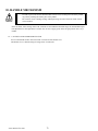
BEFORE USING THE PRODUCT, BE SURE TO READ THE FOLLOWING:
To maintain the safety:
To ensure the safe usage of the product, be sure to read the following before using the product. The following
instructions are intended for the users, operators and the personnel in charge of the operation of the product.
After carefully reading and sufficiently understanding the warning displays and cautions, handle the product
appropriately. Be sure to keep this manual nearby the product or elsewhere convenient for referring to it
when necessary.
Herein, explanations which require special attention are enclosed with dual lines. Depending on the potentially hazardous degrees, the terms of WARNING, CAUTION, etc. are used. Be sure to understand the
contents of the displays before reading the text.
WARNING!
Indicates that mishandling the product by disregarding this warning
will cause a potentially hazardous
situation which can result in death
or serious injury.
CAUTION!
Indicates that mishandling the product
by disregarding this caution will cause
a slight hazardous situation which can
result in personal injury and or material
damage.
For the safe usage of the product, the following pictographs are used:
Indicates “HANDLE WITH CARE.” In order to protect the human body an equipment, this display is attached to places where the Owner’s Manual and or Service Manual should be referred to.
Perform work in accordance with the instructions herein stated.
Instructions for work are explained by paying attention to the aspect of accident prevention. Failing to perform
work as per the instructions can cause accidents. In the case where only those who have technical expertise
should perform the work to avoid hazardous situation, the instructions herein state that the serviceman should
perform such work.
Be sure to turn off power before working on the machine.
To prevent electric shock, be sure to turn off power before starting the work in which the worker touches the interior of the product. If the work is to be performed in the power-on status, the Instruction Manual herein always
states to that effect.
Be sure to ground the Earth Terminal (this, however, is not required in the case where a power cord with earth
is used).
This product is equipped with the Earth Terminal. When installing the product, Connect the Earth Terminal to the
“accurately grounded indoor earth terminal” by using an earth wire. Unless the product is grounded appropriately,
the user can be subject to electric shock. After performing repair, etc. for the Control equipment, ensure that the
Earth Wire is firmly connected to the Control equipment.
Ensure that the Power Supply used is equipped with an Earth Leakage Breaker.
This product does not incorporate the Earth Leakage Breaker. Using a power supply which is not equipped with
the Earth Leakage Breaker can cause a fire when earth leakage occurs.
Be sure to use fuses which meet the specified rating. (only for the machines which use fuses).
Using fuses exceeding the specified rating can cause a fire and electric shock.
Specification changes (removal of equipment, conversion and addition) not designated by SEGA are not
allowed.
The parts of the product include warning labels for safety, covers for personal protection, etc. It is very hazardous to operate the product by removing parts and or modifying the circuits. Should doors, lids and protective
parts be damaged or lost, refrain from operating the product, and contact where the product was purchased from
or the office herein stated. SEGA shall not be held responsible for any accidents, compensation for damage to a
third party, resulting from the specifications not designated by SEGA.
Ensure that the product meets the requirements of appropriate Electrical Specifications.
Before installing the product, check for Electrical Specifications. SEGA products have a nameplate on which
Electrical Specifications are described. Ensure that the product is compatible with the power supply voltage and
frequency requirements of the location. Using any Electrical Specifications different from the designated Specifications can cause a fire and electric shock.
Install and operate the product in places where appropriate lighting is available, allowing warning labels
to be clearly read.
To ensure safety for the customers, labels and printed instructions describing potentially hazardous situation
are applied to places where accidents can be caused. Ensure that where the product is operated has sufficient
lighting allowing the warnings to be read. If any label is peeled off, apply it again immediately. Please place an
order with where the product was purchased from or the office herein stated.
When handling the Monitor, be very careful. (Applies only to the product w/monitor.)
Some of the monitor (TV) parts are subject to high tension voltage. Even after running off power, some portions are still subject to high tension voltage sometimes. Monitor repair and replacement should be performed
only be those technical personnel who have knowledge of electricity and technical expertise.
Be sure to adjust the monitor (projector) properly. (Applies only to the product w/monitor.)
Do not operate the product leaving on-screen flickering or blurring as it is. Using the product with the monitor
not properly adjusted may cause dizziness or a headache to an operator, a player, or the customers.
When transporting or reselling this product, be sure to attach this manual to the product.
In the case where commercially available monitors and printers are used in this product, only the contents relating to this product are explained herein. Some commercially available equipment has functions and reactions
not stated in this manual. Read this manual together with the specific Instruction Manual of such equipment.
• Descriptions herein contained may be subject to improvement changes without notice.
• The contents described herein are fully prepared with due care. However, should any question arise or errors be
found, please contact SEGA.
INSPECTIONS IMMEDIATELY AFTER TRANSPORTING THE PRODUCT TO THE LOCATION.
Normally, at the time of shipment, SEGA products are in a status allowing for usage immediately after transporting to the location. Nevertheless, an irregular situation may occur during transportation. Before turning on
power, check the following points to ensure that the product has been transported in a satisfactory status.
Are there any dented portions or defects (cuts, etc.) on the external surfaces of the cabinet?
Are Casters and Adjusters, damaged?
Do the power supply voltage and frequency requirements meet with those of the location?
Are all wiring connectors correctly and securely connected? Unless connected in the correct direction, connector
connections can not be made accurately. Do not insert connectors forcibly.
Do power cords have cuts and dents?
Do the fuses used meet specified rating? Is the Circuit Protector in an energized status?
Are all accessories available?
Can all Doors and Lids be opened with the Accessory keys? Can Doors and Lids be firmly closed?
TABLE OF CONTENTS
BEFORE USING THE PRODUCT, BE SURE TO READ THE FOLLOWING:
TABLE OF CONTENTS
INTRODUCTION OF THE OWNER’S MANUAL
1. HANDLING PRECAUTIONS ..........................................................................................
2. PRECAUTIONS CONCERNING INSTALLATION LOCATION ...................................
3. OPERATION ......................................................................................................................
4. NAME OF PARTS .............................................................................................................
5. ACCESSORIES .................................................................................................................
6. ASSEMBLING AND INSTALLATION ............................................................................
7. PRECAUTIONS WHEN MOVING THE MACHINE ......................................................
8. GAME DESCRIPTION .....................................................................................................
9. EXPLANATION OF TEST AND DATA DISPLAY .........................................................
10. HANDLE MECHANISM ..................................................................................................
11. PADDLE SHIFTER.............................................................................................................
12. ACCEL & BRAKES(S) ......................................................................................................
13. LIGHTING...........................................................................................................................
14. COIN SELECTOR .............................................................................................................
15. PROJECTOR ......................................................................................................................
16. PERIODIC INSPECTION TABLE ....................................................................................
17. GAME BOARD .................................................................................................................
18. NETWORK PLAY .............................................................................................................
19. DESIGN RELATED PARTS .............................................................................................
20. PARTS LIST .......................................................................................................................
21. WIRE COLOR CODE TABLE ..........................................................................................
22. WIRING DIAGRAMS .......................................................................................................
1 - 2
3 - 4
5 - 7
8
9 - 11
12 - 19
20
21 - 45
46 - 71
72 - 74
75 - 76
77 - 78
79 - 81
82 - 84
85 - 94
95 - 96
97 - 104
105 - 107
108
109 - 118
119
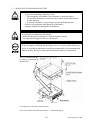
XXX
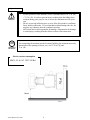
Installation Space
Height
Width
Length
Weight
Power, maximum current
PROJECTOR
SPECIFICATIONS
:
:
:
:
:
:
50.5 inches wide X 112.5 inches deep
95.5 inches
45 inches
104 inches
~unavailable at time of printing
540 W 4.5 A (AC 120V 60 Hz AREA)
: 50” PTV TOSHIBA
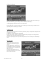
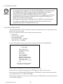
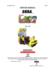
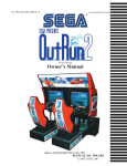
INTRODUCTION OF THE OWNERS MANUAL
This Owner's Manual is intended to provide detailed descriptions together with all the necessary
information covering the general operation of electronic assemblies, electromechanicals, servicing control, spare parts, etc. as regards the product,
OUTRUN 2 SPECIAL TOURS STANDARD TYPE.
This manual is intended for the owners, personnel and managers in charge of operation of the
product. Operate the product after carefully reading and sufficiently understanding the instructions. If the product fails to function satisfactorily, non-technical personnel should under no
circumstances touch the internal system. Please contact where the product was purchased from.
Use of this product is unlikely to cause physical injuries or damages to property. However, where
special attention is required this is indicated by a thick line, the word "IMPORTANT" and its sign in
this manual.
STOP
Indicates that mishandling the product by disregarding this display can cause the product's
intrinsic performance not to be obtained, resulting in malfunctioning.
IMPORTANT!
SEGA AMUSEMENTS USA, INC. / CUSTOMER SERVICE
45133 Industrial Drive, Fremont, California 94538, U.S.A.
Phone : (415) 701-6580
Fax : (415) 701-6594
- PRODUCTION DATE This SEGA product was produced in the year of:
2005
This signifies that this work was disclosed in 2005.
DEFINITION OF LOCATION MAINTENANCE MAN AND SERVICEMAN
WARNING!
Non-technical personnel who do not have technical knowledge and expertise should refrain from performing such work that this manual requires the location's maintenance man
or a serviceman to carry out, or work which is not explained in this manual. Failing to
comply with this instruction can cause a severe accident such as electric shock.
Ensure that parts replacement, servicing & inspections, and troubleshooting are performed by the location's
maintenance man or the serviceman. It is instructed herein that particularly hazardous work should be performed by the serviceman who has technical expertise and knowledge.
The location's maintenance man and serviceman are herein defined as follows:
"Location's Maintenance Man" :
Those who have experience in the maintenance of amusement equipment and vending machines, etc., and also
participate in the servicing and control of the equipment through such routine work as equipment assembly
and installation, servicing and inspections, replacement of units and consumables, etc. within the Amusement
Facilities and or locations under the management of the Owner and Owner's Operators of the product.
Activities of Location's Maintenance Man :
Assembly & installation, servicing & inspections, and replacement of units & consumables as regards amusement equipment, vending machines, etc.
Serviceman :
Those who participate in the designing, manufacturing, inspections and maintenance service of the equipment
at an amusement equipment manufacturer.
Those who have technical expertise equivalent to that of technical high school graduates as regards electricity,
electronics and or mechanical engineering, and daily take part in the servicing & control and repair of amusement equipment.
Serviceman's Activities :
Assembly & installation and repair & adjustments of electrical, electronic and mechanical parts of amusement
equipment and vending machines.
Notes:
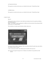
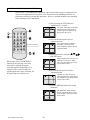
1. HANDLING PRECAUTIONS
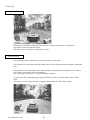
When installing or inspecting the machine, be very careful of the following points and pay attention to ensure that the player can enjoy the game safely.
Non-compliance with the following points or inappropriate handling running counter to the cautionary matters herein stated can cause personal injury or damage to the machine.
•
WARNING!
•
•
•
•
•
•
•
•
•
•
•
•
•
Before performing work, be sure to turn power off. Performing the work
without turning power off can cause an electric shock or short circuit. In the
case work should be performed in the status of power on, this manual always
states to that effect.
To avoid electric shock or short circuit, do not plug in or unplug quickly.
To avoid electric shock, do not plug in or unplug with a wet hand.
Do not expose Power Cords and Earth Wires on the surface, (floor, passage,
etc.). If exposed, the Power Cords and Earth Wires are susceptible to damage.
Damaged cords and wires can cause electric shock or short circuit.
To avoid causing a fire or electric shock, do not put things on or damage
Power Cords.
When or after installing the product, do not unnecessarily pull the power cord.
If damaged, the power cord can cause a fire or electric shock.
In case the power cord is damaged, ask for replacement through where the
product was purchased from or the office herein stated. Using the cord as is
damaged can cause fire, electric shock or leakage.
Be sure to perform grounding appropriately. Inappropriate grounding can
cause an electric shock.
Be sure to use fuses meeting specified rating. Using fuses exceeding the
specified rating can cause a fire or electric shock.
Completely make connector connections for IC BD and others. Insufficient
insertion can cause an electric shock.
Specification changes, removal of equipment, conversion and/or addition, not
designated by SEGA are not permitted.
Failure to observe this may cause a fire or an electric shock. Non-compliance
with this instruction can have a bad influence upon physical conditions of the
players or the lookers-on, or result in injury during play.
SEGA shall not be held responsible for damage, compensation for damage to
a third party, caused by specification changes not designated by SEGA.
Be sure to perform periodic maintenance inspections herein stated.
1
www.sauservice.com
STOP
•
IMPORTANT!
•
•
•
For the IC board circuit inspections, only the logic tester is allowed. The use
of a multiple-purpose tester is not permitted, so be careful in this regard.
The Projector is employed for this machine. The Projector's screen is
susceptible to damage, therefore, be very careful when cleaning the screen.
For details, refer to PROJECTOR.
Static electricity from your body may damage some electronics devices on the
IC board. Before handling the IC board, touch a grounded metallic surface so
that the static electricity can be discharged.
Some parts are the ones designed and manufactured not specifically for
this game machine. The manufacturers may discontinue, or change the
specifications of, such general-purpose parts. If this is the case, Sega cannot
repair or replace a failed game machine whether or not a warranty period has
expired.
www.sauservice.com
2
2. PRECAUTIONS CONCERNING INSTALLATION LOCATION
WARNING!
This product is an indoor game machine. Do not install it outside. Even indoors,
avoid installing in places mentioned below so as not to cause a fire, electric shock,
injury and or malfunctioning.
•
•
•
•
•
•
•
•
Places subject to rain or water leakage, or places subject to high humidity in
the proximity of an indoor swimming pool and or shower, etc.
Places subject to direct sunlight, or places subject to high temperatures in the
proximity of heating units, etc.
Places filled with inflammable gas or vicinity of highly inflammable/volatile
chemicals or hazardous matter.
Dusty places.
Sloped surfaces.
Places subject to any type of violent impact.
Vicinity of anti-disaster facilities such as fire exits and fire extinguishers.
The operating (ambient) temperature range is from 5ºC to 30ºC.
LIMITATIONS OF USAGE REQUIREMENTS
•
WARNING!
•
•
•
•
•
Be sure to check the Electrical Specifications.
Ensure that this product is compatible with the location's power supply, voltage and frequency requirements.
A plate describing Electrical Specifications is attached to the product.
Non-compliance with the Electrical Specifications can cause a fire and electric
shock.
This product requires the Breaker and Earth Mechanisms as part of the location facilities. Using them in a manner not independent can cause a fire and
electric shock.
Ensure that the indoor wiring for the power supply is rated at 10 A or higher
(AC single phase 100 ~ 120 V area). Non-compliance with the Electrical
Specifications can cause a fire and electric shock.
Be sure to independently use the power supply equipped with the Earth Leakage Breaker. Using a power supply without the Earth Leakage Breaker can
cause an outbreak of fire when earth leakage occurs.
Putting many loads on one electrical outlet can cause generation of heat and a
fire
resulting from overload.
When using an extension cord, ensure that the cord is rated at 10 A or higher
(AC 100 ~ 120 V area). Using a cord rated lower than the specified rating can
cause a fire and electric shock.
3
www.sauservice.com
Operation Area
•
WARNING!
•
•
STOP
IMPORTANT!
For the operation of this machine, secure a minimum area of 38.75 in. (W)
× 75.5 in. (D). In order to prevent injury resulting from the falling down
accident during game play, be sure to secure the minimum area for operation.
Be sure to provide sufficient space so as to allow this product's ventilation
fan to function efficiently. To avoid machine malfunctioning and a fire, do
not place any obstacles near the ventilation opening.
SEGA shall not be held responsible for damage, compensation for damage
to a third party, resulting from the failure to observe this instruction.
For transporting the machine into the location's building, the minimum necessary
dimensions of the opening (of doors, etc.) are 32.75 in. (W) and
71 in. (H).
Electric current consumption
MAX. 4.5 A (AC 120 V 60 Hz)
FIG. 2
www.sauservice.com
4
3. OPERATION
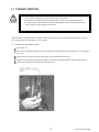
PRECAUTIONS TO BE HEEDED BEFORE STARTING THE OPERATION
To avoid injury and trouble, be sure to constantly give careful attention to the behavior and manner of the visitors and players.
In order to avoid accidents, check the following before starting the operation:
WARNING!
•
•
•
•
To ensure maximum safety for the players and the customers, ensure that
where the product is operated has sufficient lighting to allow any warnings
to be read. Operation under insufficient lighting can cause bodily contact
with each other, hitting accident, and or trouble between customers.
Be sure to perform appropriate adjustment of the monitor (projector). For
operation of this machine, do not leave monitor's flickering or deviation as
is. Failure to observe this can have a bad influence upon the players' or the
customers' physical conditions.
It is suggested to ensure a space allowing the players who feel sick while
playing the game to take a rest.
Check if all of the adjusters are in contact with the surface. If they are not,
the Cabinet can move and cause an accident.
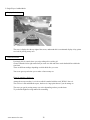
** Note: Image differs from actual product.
Ensure that all of the SUPPORT
BRACKET are in contact with the floor.
Ensure that all of the Adjusters are in contact
with the floor.
5
www.sauservice.com
•
WARNING!
•
•
•
Do not put any heavy item on this product. Placing any heavy item on the
product can cause a falling down accident or parts damage.
Do not climb on the product. Climbing on the product can cause falling down
accidents. To check the top portion of the product, use a step.
To avoid electric shock, check to see if door & cover parts are damaged or
omitted.
To avoid electric shock, short circuit and or parts damage, do not put the following items on or in the periphery of the product.
Flower vases, flowerpots, cups, water tanks, cosmetics, and receptacles/containers/vessels containing chemicals and water.
To avoid injury, be sure to provide sufficient space by considering the potentially crowded situation at the installation location. Insufficient installation
space can cause making bodily contact with each other, hitting accidents, and or
trouble between customers.
CAUTION!
PRECAUTIONS TO BE HEEDED DURING OPERATION (PAYING ATTENTION TO CUSTOMERS)
To avoid injury and trouble, be sure to constantly give careful attention to the behavior and manner of the visitors and players.
•
WARNING!
To avoid injury and accidents, those who fall under the following categories
are not allowed to play the game.
• Those who need assistance such as the use of an apparatus when walking.
• Those who have high blood pressure or a heart problem.
• Those who have experienced muscle convulsion or loss of consciousness when
playing video game, etc.
• Those who have a trouble in the neck and or spinal cord.
• Intoxicated persons.
• Pregnant women or those who are in the likelihood of pregnancy.
• Persons susceptible to motion sickness.
• Persons whose act runs counter to the product's warning displays.
•
•
•
•
•
A player who has never been adversely affected by light stimulus might experience dizziness or headache depending on his physical condition when playing the game. Especially, small children can be subject to those conditions.
Caution guardians of small children to keep watch on their children during
play.
Instruct those who feel sick during play to have a medical examination.
To avoid injury resulting from falling down and electric shock due to spilled
drinks, instruct the player not to place heavy items or drinks on the product.
To avoid electric shock and short circuit, do not allow customers to put hands
and fingers or extraneous matter in the openings of the product or small openings in or around the doors.
To avoid falling down and injury resulting from falling down, immediately
stop the customer's leaning against or climbing on the product, etc.
www.sauservice.com
6
WARNING!
•
To avoid electric shock and short circuit, do not allow the customers to unplug
the power plug without a justifiable reason.
•
This product is intended for 1 Player only per seat. Playing the game by 2 or
more Players riding on the seat together can cause falling down and collision
accidents by striking head, hand, or elbow.
•
Caution lookers-on so as not to touch the operating unit while in play.
Failure to observe this may cause bodily contact with the player and
trouble between the customers.
•Caution the player so as not to hold a child in her/his lap to play. Failure
to observe this may cause the child to be caught between the Control
Panel and the player and fall down.
•
CAUTION!
WARNING!
•
Immediately stop such violent acts as hitting and kicking the product. Such
violent acts can cause parts damage or falling down, resulting in injury due to
fragments and falling down.
Instruct the Player to adjust the seat before playing the game. Playing the
game in a forcible posture can cause a contingent accident.
WARNING: HAZARD TO EPILEPTICS.
• A very small portion of the population has a condition which may cause them
to experience epileptic seizures or have momentary loss of consciousness when
viewing certain kinds of flashing lights or patterns that are present in our daily
environment. These persons may experience seizures while watching some
kinds of television pictures or playing certain video games. People who have
not had any previous seizures may nonetheless have an undetected epileptic
condition.
• If you or anyone in your family has experienced symptoms linked to an epileptic condition (e.g., seizures or loss of awareness), immediately consult your
physician before using any video games.
• We recommend that parents observe their children while they play video
games. If you or your child experience the following symptoms: dizziness,
altered vision, eye or muscle twitching, involuntary movements, loss of awareness, disorientation, or convulsions, DISCONTINUE USE IMMEDIATELY
and consult your physician.
7
www.sauservice.com
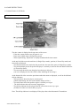
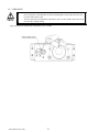
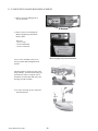
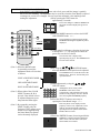
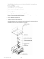
4. NAME OF PARTS
UK version and US version mount the coin tower on
opposite sides.
TABLE 4 Dimensions and Weights
When assembled
www.sauservice.com
Width x Length x
45 in x 104 in x
8
Height
95.5 in
Weight
unavailable
5. ACCESSORIES
When transporting the machine, make sure that the following parts are supplied.
Magnetic cards for the recording of play results, and cleaning kits for cleaning the head of the card
reader/writer are sold separately. Subsequent purchases of these items can be made by contacting
the office listed on this Owner's Manual or the dealer from whom the product was originally purchased. Be sure to provide the part number(s), name(s), and required number of items.
TABLE 5 a ACCESSORIES
DESCRIPTION
Part No. (Qty.)
Notes
OWNER'S MANUAL
999-2352
KEY MASTER
9301A (2)
For opening/closing
the doors
Figures
Parts not labeled with part numbers are as yet
unregistered or cannot be registered. Be sure to
handle all parts with care, as some parts are not
available for purchase separately.
KEY
(2)
For the CASHBOX DOOR
The Keys are inside the Coin
Chute Door at the time of shipment from the factory.
TAMPERPROOF
WRENCH
3/16 TMP SCR (1)
T-27 Torx 1/4-20 (1)
T-15 Torx 8/32 (1)
T-10 Torx 6/32 (1)
Tool
9
www.sauservice.com
The following Table 5b lists the parts that are separately marketed but are necessary when
booting this product's software. When having unpacked the shipping crate, make sure that all the
parts in this Table 5b are in the crate. If not so, contact where you have obtained the product.
TABLE 5 b (610-0617-01A : GD-ROM DRIVE KIT)
GD-ROM DRIVE
610-0617-01A
GD-ROM DRIVE CARTON BOX
(1)
Device that loads the software in a GD-ROM disc.
see 5 of Section 6.
Used for transporting the GD-ROM DRIVE.
See FIG. 5 b.
This carton box is a standard accessory of the
GD-ROM drive.
TABLE 5 c
GD ROM KIT ORP
CUSHION SPONGE
601-11137 (1)
GD-ROM Disc Protector
KEY CHIP (1)
CHIHIRO GDROM ORP ENG
(1)
NOTE: When you order the GD-ROM disc only, specify the part
number 610-0652-0014 (GD SOFT ORP ENG).
www.sauservice.com
10
HOW TO USE THE CARTON BOX (GD-ROM DRIVE)
STOP
IMPORTANT!
When you want to order for replacing or repairing service of the GD-ROM
drive that is used by the product, pack it in a carton box as instructed below,
and then deliver the carton box to a service agent. If you do not observe the
instruction, your order may not be accepted or may be charged additionally. If
you handle the GD-ROM drive differently from the following instructions, its
components may be damaged.
• Contain the GD-ROM drive in a dedicated carton box. Do not disassemble
it or remove any part from it unless otherwise instructed.
• Before containing the GD-ROM drive in a dedicated carton box, attach the
GD-ROM drive lid (DISC LID) onto the drive and fix the lid with a screw.
• Before containing the GD-ROM drive in a dedicated carton box, remove
the GD-ROM disk from the drive. Do not attempt to move the GD-ROM
drive with a GD-ROM disk inside.
• Before containing the GD-ROM drive in a dedicated carton box, remove
the GD-ROM drive bracket. Carefully keep the GD-ROM drive bracket
and the 4 set screws, because they will be reused.
• When inserting the GD-ROM drive into a dedicated carton box, be careful
about an inserting direction as illustrated below.
• The packing materials in a carton box are used as a cushion. Use them
always when inserting the GD-ROM drive into a dedicated carton box. Do
not bend them.
Remove the GD drive bracket.
FIG. 5 b
11
www.sauservice.com
6. ASSEMBLING AND INSTALLATION
Perform assembly work by following the procedure herein stated. Failing to comply with the
instructions can cause electric shock hazard.
Perform assembling as per this manual. Since this is a complex machine, erroneous assembling can
cause an electric shock, machine damage and or not functioning as per specified performance.
When assembling, be sure to use plural persons. Depending on the assembly work, there are some
cases in which working by one person alone can cause personal injury or parts damage.
Ensure that connectors are accurately connected. Incomplete connections can cause electric shock
hazard.
Be careful not to damage the wires. Damaged wires may cause electric shock or short circuit or present
a fire risk.
This work should be performed by the Location's Maintenance Man or Serviceman. Performing work
by non-technical personnel can cause a severe accident such as electric shock. Failing to comply with
this instruction can cause a severe accident such as electric shock to the player during operation.
Provide sufficient space so that assembling can be performed. Performing work in places with narrow
space or low ceiling may cause an accident and assembly work to be difficult.
To perform work safely and avoid serious accident such as the cabinet's falling down, do not perform
work in places where step-like grade differences, a ditch, or slope exist.
•
WARNING!
•
•
•
•
•
•
•
Handle molded parts with care. Undue weight or pressure may cause them to break and the
broken pieces may cause injury.
To perform work safely and securely, be sure to prepare a step which is in a secure and stable
condition. Performing work without using the step can cause violent falling down accidents.
Make sure that the GD cable connector is inserted parallel to the plug. Improper insertion
may cause damage to the connector and present a fire risk.
•
CAUTION!
•
•
When carrying out the assembling and installation, follow the following 4-item sequence.
1
SECURING IN PLACE(ADJUSTER ADJUSTMENT)
2
CABINET ASSEMBLY
3
POWER SUPPLY, AND EARTH CONNECTION
4
TURNING POWER ON
Tools such as a Phillips type screwdriver, wrench, socket wrench and Ratchet Handle are
required for the assembly work.
24mm
WRENCH
SOCKET WRENCH,RATCHET HANDLE
Phillips type screwdriver
www.sauservice.com
12
1
SECURING IN PLACE (ADJUSTER ADJUSTMENT)
Make sure that all of the adjusters are in contact with the floor. If they are not, the
cabinet can move and cause an accident.
WARNING!
This product has 8 casters and 8 Adjusters. (FIG. 6. 2 a) When the installation position is
determined, cause the adjusters to come into contact with the floor directly, make adjustments
in a manner so that the casters will be raised approximately 5 mm from the floor and make sure
that the machine position is level.
•
Transport the product to the
installation position.
•
Have all of the Adjusters make contact
with the floor. Adjust the Adjuster's
height by using a wrench so that the
machine position is kept level.
•
After making adjustment, fasten the
Adjuster Nut upward and secure the
height of Adjuster.
FIG. 6. 2 a BOTTOM VIEW
* Note:Picture may differ from actual unit.
FIG. 6. 2 b ADJUSTER
FIG. 6. 2 e
Provide ventilation space for the ventilation
opening.
Allow more than 28 in. of space for customer
traffic.
13
www.sauservice.com
2
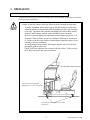
CABINET ASSEMBLY
[2.a] Assembling PTV To Main Cabinet
Before you can connect the PTV and Main Cabinet Assembly together, you have fix two connecction brackets to
each assembly.
1. Fix the connection brackets to the Main Cabinet Assembly using four M8 screws.
2. Fix the connection brackets to the PTV using four M8 screws.
Note: Removal of rear door may be necessary to facilitate the routing of the PTV harnesses.
3. Move the Main Cabinet and PTV together, close enough to facilitate connection of the video and power harnesses (stored in the Main Cabinet). Take great care when manoeuvring the PTV as it can be unstable when not secured
to the Main Cabinet.
4. Connect these harnesses to their respective sockets on the Connector Panel on the front of the PTV. Observe correct orientation of the connectors when inserting, to avoid damage. Fasten the fixing screws on the video connector
once inserted.
www.sauservice.com
14
Three M6 fixing holes
Three M6 fixing holes
5. Carefully slide the Main Cabinet and PTV together until the joint rackets overlap.
6. Use three M8 bolts to lock the brackets together.
15
www.sauservice.com
[2.b] Assembling The Coin Tower
1. Fix the Coin Tower Bracket to the Main Cabinet Assembly using two M6 screws.
2. Fix the Coin Tower to the Main Cabinet Assembly using three M8 screws.
3. Fix the Coin Tower to the Coin Tower Bracket using two M6 nuts and washers.
US model has coin tower mounted on opposite side.
www.sauservice.com
16
•
WARNING!
When moving the unit from location to location such as via truck or other
machinery, the marquee should be removed from the unit.
17
www.sauservice.com
POWER SUPPLY, AND EARTH CONNECTION
3
•
WARNING!
•
•
•
Be sure to independently use the power supply socket outlet equipped with
an Earth Leakage Breaker. Using a power supply without an Earth Leakage
Breaker can cause a fire when electric leakage occurs.
Ensure that the "accurately grounded indoor earth terminal" and the earth
wire cable are available (except in the case where a power cord plug with
earth is used). This product is equipped with the earth terminal. Connect the
earth terminal and the indoor earth terminal with the prepared cable. If the
grounding work is not performed appropriately, customers can be subjected to
an electric shock, and the product's functioning may not be stable.
Ensure that the power cord and earth wire are not exposed on the surface
(passage, etc.). If exposed, they can be caught and are susceptible to damage.
If damaged, the cord and wire can cause electric shock and short circuit
accidents. Ensure that the wiring position is not in the customer's passage
way or the wiring has protective covering.
After wiring power cord on the floor, be sure to protect the power cord.
Exposed power cord is susceptible to damage and causes an electric shock
accident.
The AC Unit is located on one side of Cabinet. The AC Unit has Main SW, Earth Terminal and
the Inlet which connects the Power Cord.
•
Ensure that the Main SW is OFF.
MAIN SW
INLET
Main SW off
FIG. 6. 4 a AC unit
* Note: Actual Power Supply connection
may vary from photo
AC Cable (Power Cord)
www.sauservice.com
18
4
TURNING POWER ON
Turn on the AC unit's main switch to supply power to the unit. Once power is turned on, the
fluorescent lamp lights up. The Start System Screen displays after a lapse of several seconds.
It is followed by the screen that indicates that the network is currently being checked if the
communication mode has been set. If there is a bad or improper communication connection, each
screen will not proceed to the next, remaining on the currently Network Check Screen. If this
occurs, resolve the error according to the instructions in this document.
If the communication mode has not been set or the communication check ends normally, the
Motor Check Screen returns. While the Motor Check Screen is on-screen, the steering wheel can
move either clockwise or counterclockwise. If you touch the wheel, the motor check is hindered
and the game will not operate normally. So, you must not touch it at this time. Failures are
displayed, if found. Resolve the errors according to the instructions in this document.
Once all the above steps have been completed, the Advertise Screen displays and voices are
output through the left and right loudspeakers, unless you have set the machine so that no voices
are output during the Advertise mode.
This product retains the number of credits and the ranking data even after the power is turned off.
It does not retain data about the fractional number of coins (i.e., the number of coins not reaching
one credit) or the bonus adder count.
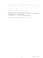
The following explanations apply to the
case the product is functioning satisfactorily.
Should there be any moves different from
the following contents, some sort of faults
may have occurred. Immediately look into
the cause of the fault and eliminate the cause
thereof to ensure satisfactory operation.
When the power is connected, the fluorescent
lamp in the FL box is always on. When in
an advertising state, the screen displays the
demonstration pictures and ranking data.
Sounds are heard from the speakers on the
right and left of the monitor. The advertising
sounds are not heard if you have set this
function to off (disabled).
The start button and the change view button
on the control panel are integrated with a
lamp.
* Note: Picture may differ from actual unit.
FIG. 6. 5
19
www.sauservice.com
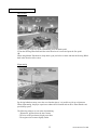
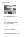
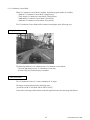
7. PRECAUTIONS WHEN MOVING THE MACHINE
•
WARNING!
•
•
CAUTION!
When moving the machine, be sure to unplug the power plug. Moving the
machine with the plug as is inserted can damage the power cord and cause fire
and electric shock hazards.
When moving the machine on the floor, retract the Adjusters and ensure
that Casters make contact with the floor. During transportation, pay careful
attention so that Casters do not tread power cords and earth wires. Damaging
the power cords can cause electric shock and short circuit hazards.
Do not push the cabinet from the left/right when attempting to move the
unit. Pushing from the sides may cause the unit to tip and result in injury and
damage to parts.
Do not push on any parts made of glass (e.g. CRT screen) or plastic, as these parts
may break and result in bodily injury.
** Note: Image differs from actual product.
Do not push the
cabinet from the
left/right direction.
FIG. 8 a
www.sauservice.com
20
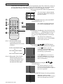
8. GAME DESCRIPTION
8-1 BASIC CONTROLS
Steering Wheel
Paddle Shifter
START and VIEW CHANGE Buttons
FIG. 8. 1
Pedals
Insert a coin and press the Start Button to begin a game.
Choose your car, game mode, background music, and other options. View choices with the Steering
Wheel, and enter your selection with the Gas pedal.
During game play with the Steering Wheel, use the Gas pedal to accelerate your car, and the Brake pedal
to stop.
The Gear Shifter can be used to shift up and shift down when using Manual transmission.
You can switch between three different view settings with the View Change Button.
21
www.sauservice.com
8-2 GAME OUTLINE
This is a driving game.
The player controls a car (Ferrari), listening to great music and enjoying roadside scenery in the
company of a gorgeous female passenger, all while racing towards the goal before time is up.
The time limit is extended at each checkpoint.
The game ends when the player runs out of time or reaches the goal.
Each game stage ends with a fork in the road where the player must decide the route using the
car during the race. There are a total of fifteen stages, and five separate goal areas. The left-hand
routes lead to less difficult stages.
A single course consists of 15 stages, with five separate goal areas.
The game has two courses, the OutRun2SP course and the OutRun2 course (from the previous
game).
The three single player game modes are OutRun Mode, Heart Attack Mode, and Time Attack
Mode.
The game's Versus Mode accommodates play for up to four players.
Route Guide with stage names
�OutRun2SP Courses
3A:
1A:
2A:
Bay Area
2B:
National Park
Sunny Beach
3B:
3C:
4A:
Lost City
4B:
Casino Town
4C:
Ice Scape
4D:
Jungle
Water Falls
Big Forest
Canyon
■OutRun2 Courses
3A:
1A:
2A:
Deep Lake
2B:
Alpine
Palm Beach
3B:
3C:
www.sauservice.com
4A:
Cloudy Highland
4B:
Industrial Complex
4C:
Snow Mountain
4D:
Ghost Forest
Castle Wall
Coniferous Forest
Desert
22
5A:
Giant Statues
5B:
Legend
5C:
Floral Village
5D:
Milky Way
5E:
Skyscrapers
5A:
Tulip Garden
5B:
Metropolis
5C:
Ancient Ruins
5D:
Imperial Avenue
5E:
Cape Way
8-3 SETUP SCREEN ORDER AND CONTENTS
This section explains the available options and controls for the setup screens.
1. Versus Mode Entry
If several machines are linked together,
inserting a coin and pressing the Start Button
on one machine will result in the message
"Entry has been closed. Please stand by." to
be displayed on the screen, following which
opposing players have the chance to enter
the race on other machines.
Any linked machines that players can race on display the message, "Waiting for entries." Other players
can join the race by inserting a coin and pressing the Start Button.
Note: See the later section "3. Versus Play Setup" for details of game flow after all players have joined
the race.
Closing Versus Mode Entry
To close Versus Mode entry, press the View Change Button and the Brake pedal at the same time before
other players join. (Press the Brake pedal while holding down the View Change Button.)
Versus Mode entry time can also be run down to "0" by holding the Start Button, thus closing Versus
Mode entry.
By closing Versus Mode entry in either of the above ways, the Single Player mode will commence,
provided no players have already joined.
Note: See the later section "2. Single Player Setup" for details of game flow after a single player race has
been selected.
23
www.sauservice.com
2. Single Player Setup
(1) Player's Car Selection
Controls: [Steering Wheel: View Choices], [Gas Pedal: Enter Selection], ["Brake Pedal" + "Shift": Color
Change]
The player can select one of the following 10 cars:
["F50", "Enzo Ferrari", "360 Spider" , "F40", "Testarossa", "288 GTO", "512 BB", "Dino 246 GTS",
"365 GTS/4, Daytona", "250 GTO"]
Changing the Car Color
Pressing the Brake pedal displays the available colors for the player's car at the bottom-right of the
screen. A color can be selected by moving the Gear Shifter up or down. In accordance with the selected
color, the color of the car displayed on the screen also changes.
www.sauservice.com
24
(2) Transmission Selection
Controls: [Steering Wheel: View Choices], [Gas Pedal: Enter Selection]
After the player has selected a car, they can then choose the type of transmission.
•Automatic Transmission:
Shifting up and down gears is performed automatically (the player does
not use the Gear Shifter).
•Manual Transmission:
The player shifts up and down gears using the Gear Shifter.
For Manual Transmission, the number of gears depends on the model of the car.
6-Speed: F50, Enzo Ferrari, 360 Spider
5-Speed: F40, Testarossa, 288 GTO, 512 BB, Dino 246 GTS, 365 GTS/4 Daytona, 250 GTO
25
www.sauservice.com
(3) Game Mode Selection
Controls: [Steering Wheel: View Choices], [View Change Button: OutRun2/OutRun2SP], [Gas Pedal:
Enter Selection]
The player selects which game mode they will play.
• OutRun Mode:
<Try to reach the goal with your girlfriend.>
Earn points by overtaking enemy or rival cars on your way to the finish line.
• Heart Attack Mode:
<Try to get as many "HEARTS" as possible by meeting your girlfriend's
demands.>
Carry out the various requests your girlfriend makes and try to accumulate
hearts.
• Time Attack Mode:
<Drive against the Ghost Car and challenge for the course record!!>
Compete against the fastest time achieved by another player on the machine
(the ghost car) to set a new record.
Note: See the section "8-4 Game Instructions" for further details of each mode.
Pressing the View Change Button allows the player to select the course from the previous game,
OutRun2.
Pressing the View Change Button again allows the player to select the OutRun2SP course.
www.sauservice.com
26
(4) Game Mode Selection (15-Continuous Course Mode)
When the 15-Continuous Course Mode is available, two icons for that mode are added to the game mode
selection screen.
Note: See the section "Test Mode" for information on how to setup 15-Continuous Course Mode.
Points about the additional 15-Continuous Course Mode:
• OutRun 15-Continuous Course Mode:
This allows the player to race 15 consecutive stages in OutRun Mode.
• Time Attack 15-Continuous Course Mode:
This allows the player to race 15 consecutive stages in Time Attack Mode.
Note: See the section "8-4 Game Instructions" for details of the 15-Continuous Course.
If the player has insufficient credits to play the 15-Continuous Course Mode, the outstanding required
credits are displayed above the course icons. In this state, it is not possible to select that mode.
27
www.sauservice.com
Pressing the View Change Button enables the selection of courses from the previous game, OutRun2. It is
possible to select a 15-Continuous Course from OutRun2.
(5) Settings Selection (Time Attack Mode only)
In Time Attack Mode, the player proceeds to the car settings screen after selecting the game mode.
Controls: [Steering Wheel: View Choices], [Gas Pedal: Enter Selection]
The following settings are available:
• Normal: Emphasis on handling, with a top speed of 293 km/h.
• Tuned:
Emphasis on speed, reaching 300 km/h maximum.
Note: The Tuned setting is aimed at experienced players as handling is made more difficult.
www.sauservice.com
28
(6) BGM Selection
Controls: [Steering Wheel: View Choices], [View Change Button: Music Change], [Gas Pedal: Enter
Selection], [Brake Pedal + Shift: Sound Balance Change]
The in-game background music can be chosen from a total of 14 different tunes.
By selecting the RANDOM icon on the far right, the music will be selected at random.
The list of selectable music can be changed by pressing the View Change Button.
� BGM List: First screen
- SPLASH WAVE
- MAGICAL SOUND SHOWER
- PASSING BREEZE
- Risky Ride
- Shiny World
- Night Flight (Includes lyrics)
- Life was a bore (Includes lyrics)
� BGM List: Second screen
- SPLASH WAVE -1986- MAGICAL SOUND SHOWER -1986- PASSING BREEZE -1986- Shake the Street -1989- Rush a Difficulty -1989- Who are you -1989- Keep Your Heart -1989-
29
www.sauservice.com
Sound Balance Adjustment
Pressing the Brake pedal brings up the sound balance window at the bottom right of the screen. The
sound balance can be adjusted by moving the Gear Shifter up or down.
Depending on the chosen sound balance, the relative volume of the BGM and engine noise varies.
3. Versus Play Setup
(1) Versus Stage Selection
Controls: [Steering Wheel: View Choices], [Gas Pedal: Enter Selection]
The player selects which stages the race will contain.
• Special:
A course specially designed for versus races.
This course combines stages from both OutRun2SP and OutRun2.
• OutRun2SP:
The OutRun2SP course.
• OutRun2:
The OutRun2 course.
www.sauservice.com
30
(2) Versus Stage Selection (15-Continuous Course Mode)
When the 15-Continuous Course Mode is available, two icons for that mode are added to the versus stage
selection screen.
Note: See the section "Test Mode" for information on how to setup 15-Continuous Course Mode.
Points about the additional 15-Continuous Course Mode:
• OutRun2SP 15-Continuous Course Mode:
This allows the player to race 15 consecutive stages in OutRun2SP Mode.
• OutRun2 15-Continuous Course Mode:
This allows the player to race 15 consecutive stages in OutRun2 Mode.
Note: See the "8-4 Game Instructions" section for details of the 15-Continuous Course Mode.
If the player has insufficient credits to play the 15-Continuous Course Mode, the outstanding required
credits are displayed above the course icons. In this state, it is not possible to select that mode.
It is only possible to play the 15-Continuous Course Mode if all drivers participating in the race select it.
31
www.sauservice.com
(3) Player's Car Selection
Controls: [Steering Wheel: View Choices], [Gas Pedal: Enter Selection], [Brake pedal + Shift: Player
Only Mode "PO" Entry], ([View Change + Shift: No Handicap "NH" Entry])
As with Single Player mode, there are 10 cars to choose from.
In Versus Play mode, car colors are fixed - Player 1: Red, Player 2: Yellow, Player 3: White or Silver
(depending on the car model), Player 4: Black.
No Handicap Setup
When a player is in 2nd position or below during Versus Play, they are compensated to help them catch
the lead driver more easily.
No Handicap is a mode without this compensation.
Pressing [View Change + Shift] (moving the Gear Shifter while pressing the View Change Button)
displays the "NH" icon on the left edge of the screen.
If all players participating in the race perform this operation, the race will take place in No Handicap
mode.
Player Only Setup
In Player Only mode, no cars appear
during the race other than the player's
own car.
Pressing [Brake Pedal + Shift] (moving
the Gear Shifter while pressing the Brake
Pedal) displays the "PO" icon on the left
edge of the screen.
If all players participating in the race
perform this operation, the race will take
place in Player Only mode.
www.sauservice.com
32
(4) Transmission Selection
This operation is carried out in the same way as described in the section "2. Single Player Setup".
(5) BGM Selection
This operation is carried out in the same way as described in the section "2. Single Player Setup".
4. Special Controls
Shortcut
During setup, the player can choose to start with the same settings as the previous game by performing
the following operation:
[Brake + View Change + Shift Up (putting the Gear Shifter in the down position while pressing the Brake
Pedal and the View Change Button)].
This combination of controls opens the shortcut window on the screen.
By turning the Steering Wheel to highlight "YES" and selecting it with the Gas pedal, play starts with the
same settings as the previous game.
If "NO" is selected, the window closes and the player is returned to the setup screen.
Note: If the previous game was played in 15-Continuous Course Mode it is not possible to use this
shortcut.
33
www.sauservice.com
8-4 GAME INSTRUCTIONS
1. Common Features in All Modes
Display Breakdown (All Modes)
The time counter is displayed at the top-center of the screen.
- If the time counter reaches zero, the game is over.
- Extra time is added when a checkpoint is passed.
- When slipstreaming, "Slipstream" is displayed underneath the time counter.
At the top-left of the screen the total time (in Single Player mode), position (in Versus Play mode) and
route map are displayed.
- The total time shows how much time has passed since the start of the game (in Single Player mode).
- The position display shows the position the player is currently in, between the start and the finish line
(in Versus Play mode).
- The route map shows the route the player has taken up to this point.
(An icon is displayed to the side of this at forks indicating the next stage.)
At the bottom-left of the screen the speed meter and tacho meter are displayed, as well as the shift and
shift-up indicators.
- The speed meter shows the player's current speed.
(When slipstreaming, the color of the number changes to blue.)
- The tacho meter shows the speed the engine is currently revving at.
- The shift indicator shows the currently engaged gear.
- The shift-up indicator lets the player know the correct time to move up a gear.
(It flashes red when it is time to shift up a gear.)
Note: The shift-up indicator is not displayed if the player has selected Automatic Transmission.
www.sauservice.com
34
Game Controls (All Modes)
How to Drift
1)After letting go of the Gas pedal, immediately press the Brake pedal.
2)Turn the Steering Wheel hard and fast in the direction of a corner and press the Gas pedal.
OR
When using Manual Transmission, drop down a gear just before a corner and turn the Steering Wheel
hard in the direction of the corner.
Slipstreaming
By driving behind an enemy car or the car of another player, it is possible to pick up a slipstream.
When slipstreaming, the player experiences enhanced acceleration and can drive faster than the car's
specified top speed.
The following changes are seen when slipstreaming:
- "Slipstream" appears below the time counter.
- The color of the speed meter display turns blue.
- The engine noise becomes slightly louder.
35
www.sauservice.com
2. Single Player: OutRun Mode
Display Breakdown
The score is displayed at the top-right of the screen, underneath this is an animated display of any points
received for passing enemy cars.
Game Instructions
Put simply, this is a mode where you enjoy taking a drive with a girl.
Choose either the left or right road when you come to a fork and aim to reach the finish line within the
time limit.
There are different endings depending on which finish line you cross.
Your score goes up each time you overtake a faster enemy car.
Hints for attaining a high score
Among the enemy cars there is a rival car which is marked with the word "RIVAL" above it.
The rival car is fast and difficult to pass, but there is a large point bonus if you do manage to.
The score you get for passing enemy cars varies depending on how you take them.
Try to find the highest scoring method for overtaking.
www.sauservice.com
36
3. Single Player: Heart Attack Mode
Display Breakdown
The number of hearts collected is displayed at the top-right of the screen.
At the bottom-right of the screen, the total number of hearts collected and a girl's silhouette is displayed.
As the total number of hearts collected increases, the girl's silhouette is filled out with color.
Game Instructions
In this mode, you impress a beautiful girl by doing everything she asks.
You must collect hearts which give an indication of how impressed the girl is with you.
You have to carry out the girl's requests in the interval between "START" and "END" being displayed.
You collect hearts in accordance with how well you carry out the various requests your girl asks of you.
The girl rates your performance in the following levels:
[AAA, AA, A, B, C, D, E]
Hints for picking up a lot of hearts
Crashing or bumping into enemy cars reduces the number of hearts you can get, so drive carefully.
If you continually achieve good ratings you may be given a "Special Request". That's your chance to
really impress her and get a triple-A score!
37
www.sauservice.com
4. Single Player: Time Attack Mode
Display Breakdown
At the top-right of the screen, the lap time for each stage is displayed.
(If the time is faster than the ghost car, it is displayed in green.)
At the bottom-right of the screen, the time for each sector of the stage is displayed.
When each sector is completed, ghost car information is displayed on the center left and right of the
screen.
[On the left is data for the ghost car that took the left-hand road at the fork.]
[On the right is data for the ghost car that took the right-hand road at the fork.]
The data is displayed in the following order:
• The ghost car icon (model and color), and the ghost car driver's name.
• Ghost: The ghost car's sector completion time.
• Player: The player's sector completion time.
• Diff:
The time difference between the ghost car and player's completion times.
(In green if the player is faster than the ghost car or red if the player is slower.)
The car's setup and transmission are shown at the bottom-left of the screen.
Game Instructions
In this mode you compete against the ghost car's time.
You aim to overtake the ghost car on each course and record your own fastest time to become the ghost
car.
The ghost car represents the fastest recorded time on each stage.
If you drive faster than the ghost car, your player data will be recorded as the ghost car data, and any
subsequent plays of the same stage will operate with your car as the ghost car.
www.sauservice.com
38
If you enter your name on the name entry screen you can also add that to the ghost car data.
Even if you quit the game part way through, if you have recorded a faster time than the ghost car, you
will have the opportunity to enter your name.
Each stage has data for two ghost cars; one which took the left-hand road at the fork and one which took
the right-hand road.
The fifth stage has no fork so there is only data for one ghost car.
The fastest player on each course is saved separately as the top ghost car.
If you enter the fifth stage within 1 second of the fastest player, the top ghost car appears in addition to
the normal ghost car. ("TOP" is shown above the car.)
If you beat the top ghost car, you become the fastest player for that course.
Pressing the Start Button toggles the display of the ghost car on and off.
39
www.sauservice.com
5. Versus Play
Display Breakdown
Opponent data is displayed at the top-right of the screen.
Each player's information is indicated with a face icon, and their current status is shown by the
expressions on the faces and with speech.
The order of the faces changes to reflect the race order.
Game Instructions
The starting grid order is determined by the order of entry into the game.
The first player to reach a fork can decide whether the race will continue down the left-hand or right-hand
road.
It is possible to set "No Handicap" mode, which eliminates compensation for trailing drivers, or "Player
Only" mode, where enemy cars are not displayed.
Note: See the previous section "3. Versus Play Setup" for details.
As soon as one of the competing players passes the finish line, the time counter display shows "Extra
Time".
The game is over for players who do not manage to finish within the "Extra Time" period.
www.sauservice.com
40
6. 15-Continuous Course Mode
When 15-Continuous Course Mode is enabled, the following game modes are available:
- "OutRun 15-Continuous Course Mode" (Single Player)
- "Time Attack 15-Continuous Course Mode" (Single Player)
- "OutRun2SP 15-Continue Course Mode" (Versus Play)
- "OutRun2 15-Continuous Course Mode" (Versus Play)
The 15-Continuous Course Mode differs from the normal game in the following ways:
Display Breakdown
The following differences are exhibited in the 15-Continuous Course Mode:
- The route map changes to the 15-Continuous Course map.
- In Versus Play, the position display is modified.
Game Instructions
The 15-Continuous Course is a course combining all 15 stages.
The stages are interconnected in the following order:
[1A:2A:2B:3A:3B:3C:4A:4B:4C:4D:5A:5B:5C:5D:5E]
At the end of each stage, both branches of the left-right fork lead to the same stage that follows.
41
www.sauservice.com
7. Game Pause
The game can be paused with the following combination of controls (in Single Player mode only):
With the car stopped, press [Brake + View Change + Shift Up (Put the Gear Shifter in the down position
while pressing the Brake Pedal and View Change Button down)]
This combination of controls opens the pause window on the screen.
By turning the Steering Wheel to highlight "YES" and selecting it with the Gas pedal, the game comes to
an end.
If "NO" is selected game play resumes.
(After "NO" has been selected once, it is no longer possible to use the game pause command again.)
The game pause command will not work in the following circumstances:
1) When the player is in the vicinity of the start area.
2) When the remaining time is 8 seconds or less.
3) When the game has already been paused once before, and "NO" was selected.
www.sauservice.com
42
8-5 NAME ENTRY AND INTERNET RANKING
1. Name Entry
Controls: [Steering Wheel: View Choices], [Gas Pedal: Enter Selection], [Brake Pedal: Delete], [Start
Button: END] (Moving the Gear Shifter up and down selects letters.)
This game has a function that can register all Single Player results with an Internet ranking system.
After finishing a game in Single Player mode, the player enters their name for Internet ranking purposes,
even if they have not achieved a rank on the actual machines they are playing on.
If the player gets into the ranking on the machine they are using, the name they enter will be used in that
machine's advertising demo display.
If the player makes a new ghost car record, their name is displayed with the new ghost car data.
43
www.sauservice.com
2. Internet Ranking
After the player has entered their name, an Internet ranking password is displayed.
Pressing the View Change Button switches to the game's in-depth data display.
Visit the following URL for Internet ranking registration and listings: http://outrun.jp/
The Internet ranking is calculated separately for the following game modes and courses:
OutRun2SP Courses
• OutRun Mode:
• Heart Attack Mode:
• Time Attack Mode [Normal, AT]:
• Time Attack Mode [Normal, MT]:
• Time Attack Mode [Tuned, AT]:
• Time Attack Mode [Tuned, MT]:
Each course (A - E) + the 15-Continuous Course
Each course (A - E)
Each course (A - E) + the 15-Continuous Course
Each course (A - E) + the 15-Continuous Course
Each course (A - E) + the 15-Continuous Course
Each course (A - E) + the 15-Continuous Course
OutRun2 Courses
• OutRun Mode:
• Heart Attack Mode:
• Time Attack Mode [Normal, AT]:
• Time Attack Mode [Normal, MT]:
• Time Attack Mode [Tuned, AT]:
• Time Attack Mode [Tuned, MT]:
Each course (A - E) + the 15-Continuous Course
Each course (A - E)
Each course (A - E) + the 15-Continuous Course
Each course (A - E) + the 15-Continuous Course
Each course (A - E) + the 15-Continuous Course
Each course (A - E) + the 15-Continuous Course
www.sauservice.com
44
8-6 CHARACTER INTRODUCTIONS
Three major characters appear in the game.
1. Driver
Name:
Alberto
Personal Info: Although easy-going on the outside, he's a real go-getter.
He has a very distinguished driving sense. He's also quite rich.
2. OutRun Mode Lady
Name:
Jennifer
Personal Info: She's a filthy rich 'princess', always selfishly seeking the next thrill. She's involved with
Alberto, his Ferrari a present from her. She has a sharp eye for driving techniques.
3. Heart Attack Lady
Name:
Clarissa
Personal Info: She's peppy and unmistakably sexy. A driving fan, with a weakness for thrill rides.
She's very demanding, but her sweet character makes her hard to dislike.
45
www.sauservice.com
9. EXPLANATION OF TEST AND DATA DISPLAY
By operating the switch unit, periodically perform the tests and data check. When installing the
machine initially or collecting cash, or when the machine does not function correctly, perform
checking in accordance with the explanations given in this section.
The following shows tests and modes that should be utilized as applicable.
This product's basic system consists of the Chihiro game board and the GD-ROM drive. The
system enables you to play several games one after the other just by changing a GD-ROM disc
that is to be set on the GD-ROM drive.
The product supports, therefore, the following 2 test modes:
(1) System test mode for an automatic self-diagnostic test (generally used by every product that
contains the basic system) and a coin assignment (specifically used by this product) and
(2) Game test mode for testing the input/output control devices and setting the difficulty level
(specifically used by this product).
TABLE 9. EXPLANATION OF TEST MODE
ITEMS
DESCRIPTION
REFERENCE
SECTIONS
INSTALLATION
OF MACHINE
When the machine is installed, perform the following:
1. Check to ensure each is the standard setting at shipment.
2. Check each Input equipment in the INPUT TEST mode.
3. Check each Output equipment in the OUTPUT TEST mode.
4. Test on-IC-Board IC's in the self-test mode.
MEMORY TEST
This test is automatically executed by selecting MEDIA BOARD
TEST or SYSTEM INFORMATION in the Menu mode.
PERIODIC
SERVICING
Periodically perform the following:
1. MEMORY TEST
2. Ascertain each setting.
3. To test each Input equipment in the INPUT TEST mode.
4. To test each Output equipment in the OUTPUT TEST mode.
CONTROL
SYSTEM
1. To check each Input equipment in the INPUT TEST mode.
2. Adjust or replace each Input equipment.
3. If the problem still remains unsolved, check each equipment's
mechanism movements.
MONITOR
In the Monitor Adjustment mode, check to see if Monitor (Projector) adjustments are appropriate.
9-2F
14
IC BOARD
MEMORY TEST
9-2B, C, D
DATA CHECK
Check such data as game play time and histogram to adjust the
difficulty level, etc.
9-3E
www.sauservice.com
46
9-3D
9-3A
9-3B
9-2B, C, D
9-2B, C, D
9-2B, C, D
9-2G, 9-3D
9-3A
9-3B
9-3A
9-3C
10, 11, 12
9-1 SWITCH UNIT AND COIN METER
CAUTION!
Never touch places other than those specified. Touching places not specified can cause
electric shock and short circuit accidents.
STOP
•
IMPORTANT!
•
Adjust the sound to the optimum volume, taking into consideration the
environmental requirements of the installation location.
Removing the Coin Meter circuitry renders the game inoperable.
SWITCH UNIT
Open the coin chute door, and the switch unit shown will
appear.
The functioning of each SW is as follows:
FIG. 9. 1 a SWITCH UNIT
• SOUND VOLUME:
Adjusts sound volume for all of the machines' Speakers.
• TEST BUTTON:
For the handling of the test button, refer to the following pages.
• SERVICE BUTTON:
Gives credits without registering on the coin meter.
(SPEAKER)
(TEST)
(SERVICE)
• DEMAGNETIZER SWITCH: Eliminates the on-screen color unevenness due to magnetization of
(DEMAG.)
CRT. First use this SW before performing the monitor's color adjustment.
COIN METER
Open the Cashbox Door by using the key to have the Coin Meter
appear underneath the Cashbox.
COIN METER
FIG. 9. 1 b
47
www.sauservice.com
9-2 SYSTEM TEST MODE
STOP
•
IMPORTANT!
•
•
•
Any settings that are changed by users during TEST MODE are saved upon exiting
TEST MODE with the EXIT command in the SYSTEM MENU. If the unit is
powered off prior to exiting, changes to settings will not take effect.
You may not enter GAME TEST MODE while the unit is reading from or checking
the GD-ROM. If error messages are displayed when exiting TEST MODE, you
should power the unit off and on again.
In the manual for this product, "Media Board" and "DIMM" are one and the same.
Use with the specified settings. If settings other than those specified are used,
inappropriate operations or malfunction may occur.
A. SYSTEM TEST MENU MODE
System Test Mode can be used to check that the main circuit operations are correct, adjust Monitor color,
and perform coin/credit settings.
However, this product can only be used with the settings shown below.
• SOUND TEST
- OUTPUT TYPE: STEREO
• COIN ASSIGNMENTS
- COIN CHUTE TYPE: COMMON
- SERVICE TYPE: COMMON
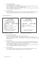
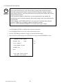
• Press the TEST Button after powering on the unit to display the following SYSTEM MENU.
SYSTEM MENU
MEDIA BOARD TEST
SYSTEM INFORMATION
JVS TEST
SOUND TEST
C.R.T. TEST
COIN ASSIGNMENTS
CLOCK SETTING
NETWORK SETTING(CORE)
NETWORK SETTING(MEDIA)
ENTER GAME TEST
[*******************]
→EXIT
SELECT WITH SERVICE BUTTON
AND PRESS TEST BUTTON
• Press the SERVICE Button to move the cursor to the desired test item.
• Move the cursor to the desired item and press the TEST Button to display each test screen.
• Move the cursor to ENTER GAME TEST and press the TEST Button to enter the individual test menus
for each game. Refer to "9-3 GAME TEST MODE".
• When testing is complete, move the cursor to EXIT and press the TEST Button. The game advertisement
screen should be displayed.
www.sauservice.com
48
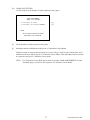
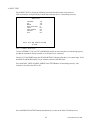
B. MEDIA BOARD TEST
STOP
IMPORTANT!
Powering off the system during the MEDIA BOARD TEST with a DIMM BOARD will
erase the game program data. It may be necessary to reload the data.
Always wait for the test to complete before attempting to exit.
MEDIA BOARD TEST is used to check the memory and IC on the MEDIA BOARD connected to the
Chihiro. Test screens and test times may differ depending on the type of MEDIA BOARD connected to
the unit.
l The following is the MEDIA BOARD TEST screen for a unit with a DIMM BOARD.
MEDIA BOARD TEST 1/2
DIMM BOARD(TYPE3)
VERSION ****
STATUS
GOOD
CHECKING 100%
DIMM TEST
DIMM0
DIMM1
GD-ROM
GOOD
NONE
GOOD
PRESS TEST BUTTON TO EXIT
l
MEDIA BOARD TEST begins immediately upon entering this test mode.
l
If "GOOD" is displayed to the right of each item, the MEDIA BOARD components are functioning
properly.
l
Press the TEST Button to display the following screen.
MEDIA BOARD TEST 2/2
NETWORK BOARD
VERSION ****
STATUS
GOOD
CHECKING 100%
NETWORK BOARD TEST
RAM CHECK-GOOD
--COMPLETED--
PRESS TEST BUTTON TO EXIT
l
After the test is complete, move the cursor to EXIT and press the TEST Button to return to the SYSTEM
MENU screen.
49
www.sauservice.com
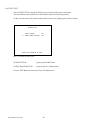
C. SYSTEM INFORMATION
Use SYSTEM INFORMATION to check version and other information for system programs.
Screens may differ depending on the type of MEDIA BOARD connected to the unit.
SYSTEM INFORMATION
MAIN BOARD
REGION
****
BOOT VERSION
****
QC FIRM VERSION
****
SC FIRM VERSION
****
SERIAL NO. ***************
MEDIA BOARD
DIMM BOARD(TYPE3) + GDROM
MEMORY SIZE
512MB
FIRM VERSION
****
SERIAL NO. ***************
NETWORK BOARD
FIRM VERSION
****
(A)
(B)
(B)
(B)
(C)
(D)
(E)
(F)
(G)
(H)
PRESS TEST BUTTON TO EXIT
Press the TEST Button to return to the SYSTEM MENU screen.
(A)
REGION
The COUNTRY CODE of the MAIN BOARD.
(B)
BOOT VERSION, QC FIRM VERSION, SC FIRM VERSION
Version information for the MAIN BOARD system programs.
(C)
SERIAL NO.
Serial number of the MAIN BOARD.
(D)
DIMM BOARD + GDROM
Type of MEDIA BOARD. This example shows a DIMM BOARD with a GD-ROM DRIVE connected.
(E)
MEMORY SIZE
Capacity of DIMM memory installed on the DIMM BOARD.
(F)
FIRM VERSION
Version information for the DIMM BOARD system program.
(G)
SERIAL NO.
Serial number of the DIMM BOARD.
(H)
FIRM VERSION
Version information for the NETWORK BOARD system program.
www.sauservice.com
50
D. JVS TEST
JVS TEST is used to verify the specs of the I/O BOARD connected to the Chihiro and to run input tests.
I/O BOARD specs are displayed initially.
Screens may differ depending on the type of I/O BOARD connected to the unit.
JVS TEST
INPUT TEST
NEXT NODE
→EXIT
NODE
****
NAME
****************
I/O BD JVS
Ver****
*********
CMD VER
1.1
JVS VER
2.0
COM VER
1.0
SWITCH
2 PLAYER(S) 13 BITS
COIN
2 SLOT
ANALOG
8 CH
ROTARY
0 CH
KEYCODE
0
SCREEN
X:0 Y:0 CH:0
CARD
0 SLOT
HOPPER OUT 0 CH
DRIVER OUT 6 CH
ANALOG OUT 0 CH
CHARACTER CHARA:0 LINE:0
BACKUP
0
SELECT WITH SERVICE BUTTON
AND PRESS TEST BUTTON
l
Use the SERVICE Button to move the cursor to the desired test item.
l
Move the cursor to INPUT TEST and press the TEST Button to enter the INPUT TEST screen for the I/O
BOARD currently displayed.
l
When 2 or more I/O BOARDS are connected, move the cursor to NEXT NODE and press the TEST
Button to enter the test screen for the next I/O BOARD. The lower the NODE number, the further away
the node is from the Chihiro.
l
Move the cursor to EXIT and press the TEST Button to return to the SYSTEM MENU screen.
51
www.sauservice.com
INPUT TEST Screen
JVS TEST
INPUT TEST
NODE
SYSTEM
PLAYER
PLAYER
COIN 1
COIN 2
ANALOG
ANALOG
ANALOG
ANALOG
ANALOG
ANALOG
ANALOG
ANALOG
1
2
1
2
3
4
5
6
7
8
1/1
00
0000
0000
0000
0000
0000
0000
0000
0000
0000
0000
0000
0000
(A)
(A)
(A)
(B)
(B)
(C)
(C)
(C)
(C)
(C)
(C)
(C)
(C)
PRESS TEST AND SERVICE BUTTON TO EXIT
l
l
On-screen values change according to the input from switches and the volume.
(A)
SYSTEM, PLAYER
Values change with input from control panel/other switches.
(B)
COIN
Increases with input from the COIN SWITCH. The count is cleared when exiting TEST
MODE.
(C)
ANALOG
Displays analog values from "0000" to "FFFF".
Press the SERVICE and TEST Buttons simultaneously to return to the JVS TEST main screen.
www.sauservice.com
52
E. SOUND TEST
Use SOUND TEST to test sound output and to select the stereo/mono/surround setting.
SOUND TEST
OUTPUT TYPE
RIGHT SPEAKER
LEFT SPEAKER
→EXIT
(A)
(B)
(B)
STEREO
OFF
OFF
SELECT WITH SERVICE BUTTON
AND PRESS TEST BUTTON
l
Use the SERVICE Button to move the cursor to the desired test item.
l
Press the TEST Button to enter the selected item.
l
(A)
OUTPUT TYPE(STEREO, MONO, SURROUND)
Select the sound output from the I/O PANEL audio output interface setting among
STEREO, MONO and SURROUND.
(B)
RIGHT/LEFT SPEAKER(ON, OFF)
When set to "ON", the test sends a beep to each audio output interface. Only the word
"SPEAKER" is displayed when the OUTPUT TYPE is set to "MONO", and when set to
"ON", the test sends the same beep to both the left/right audio output interfaces.
To test surround output, it is necessary to use a separate Audio Amp, and receive signal
from a terminal not in use at the time of shipping.
Note: Not available with this product.
Move the cursor to EXIT and press the TEST Button to return to the SYSTEM MENU screen.
53
www.sauservice.com
F. C.R.T. TEST
Use the C.R.T. TEST to adjust monitor colours and verify screen size.
COLOR CHECK Screen
l
Monitor COLOR CHECK screen is displayed initially.
Each of the colors (red, green and blue) is darkest at the far left and gets progressively lighter (32 steps)
towards the right.
Monitor brightness is set correctly if the white color bar is black at the left edge and white at the right
edge.
C.R.T. TEST 1/2
1
32
RED
GREEN
BLUE
WHITE
PRESS TEST BUTTON TO CONTINUE
l
Press the TEST Button to proceed to the next page.
SIZE CHECK Screen
C.R.T. TEST 2/2
PRESS TEST BUTTON TO EXIT
l
Adjust the CHECK GRID so that the entire GRID is displayed on the screen.
l
Press the TEST Button to return to the SYSTEM MENU screen.
www.sauservice.com
54
G. COIN ASSIGNMENTS
Use COIN ASSIGNMENTS to set the credit rate for each coin inserted.
l
Use the SERVICE Button to move the cursor to the desired test item.
l
Press the TEST Button to change the setting or to open the detailed settings.
l
Move the cursor to EXIT and press the TEST Button to return to the SYSTEM MENU screen.
COIN ASSIGNMENTS
COIN CHUTE TYPE
SERVICE TYPE
COIN CHUTE #1 COIN
1 COIN(S) COUNT AS
COIN CHUTE #2 COIN
1 COIN(S) COUNT AS
DETAIL SETTING
GAME COST SETTING
→EXIT
COMMON
COMMON
TO CREDIT RATE
1 CREDIT(S)
TO CREDIT RATE
1 CREDIT(S)
COIN ASSIGNMENTS
(A)
(B)
COIN CHUTE TYPE
SERVICE TYPE
(C)
COIN CHUTE #1 COIN TO CREDIT RATE
1 COIN(S) COUNT AS 1 CREDIT(S)
(C)
(D)
(H)
DETAIL SETTING
GAME COST SETTING
→EXIT
SELECT WITH SERVICE BUTTON
AND PRESS TEST BUTTON
COIN CHUTE TYPE…COMMON
(A)
INDIVIDUAL
INDIVIDUAL
SELECT WITH SERVICE BUTTON
AND PRESS TEST BUTTON
COIN CHUTE TYPE…INDIVIDUAL
COIN CHUTE TYPE(COMMON, INDIVIDUAL)
Adjust settings according to the specs of the cabinet COIN CHUTE.
COMMON
This is for cabinets where a single COIN CHUTE is used by multiple players.
Coins inserted by each player are treated as common credits.
Up to 2 COIN CHUTES (#1 and #2) may be used. The (C) COIN TO CREDIT RATE setting
for COIN CHUTE #1 and #2 may be set differently.
INDIVIDUAL
This is for cabinets with individual COIN CHUTES for each player.
Coins inserted by each player are treated as individual player credits.
The (C) COIN TO CREDIT RATE setting is used by all COIN CHUTES.
(B)
SERVICE TYPE(COMMON, INDIVIDUAL)
Use this to set the function of each SERVICE Button when there is more than one SERVICE
Button.
COMMON
Pressing any SERVICE Button enters service credits for all players.
INDIVIDUAL
Pressing the SERVICE Button enters service credits only for the corresponding player.
55
www.sauservice.com
(C)
COIN TO CREDIT RATE
Set the CREDIT RATE for each coin inserted.
The "x COIN(S) COUNT AS y CREDIT(S)" setting indicates that "Inserting x coins equals y credits".
Set this to "FREE PLAY" to allow game play without credits.
When (A) COIN CHUTE TYPE is set to "COMMON", COIN CHUTE #2 settings are restricted to some
extent by the settings for COIN CHUTE #1.
(D)
DETAIL SETTING
This mode allows for more detailed credit rate settings than the (C) COIN TO CREDIT RATE setting.
Changes made in DETAIL SETTING override any (C) COIN TO CREDIT RATE settings.
DETAIL SETTING Screen
COIN ASSIGNMENTS
DETAIL SETTING
COIN CHUTE #1 MULTIPLIER
1 COIN COUNT AS 1 COIN(S)
COIN CHUTE #2 MULTIPLIER
1 COIN COUNT AS 1 COIN(S)
BONUS ADDER
NO BONUS ADDER
COIN TO CREDIT
1 COIN(S) 1 CREDIT
→EXIT
COIN CHUTE #1 OPERATION
COIN
1 2 3 4 5 6 7 8 9
CREDIT 1 2 3 4 5 6 7 8 9
COIN CHUTE #2 OPERATION
COIN
1 2 3 4 5 6 7 8 9
CREDIT 1 2 3 4 5 6 7 8 9
SELECT WITH SERVICE BUTTON
AND PRESS TEST BUTTON
COIN CHUTE TYPE…COMMON
COIN ASSIGNMENTS
DETAIL SETTING
COIN CHUTE #1 MULTIPLIER
1 COIN COUNT AS 1 COIN(S)
(E)
(E)
(F)
(G)
BONUS ADDER
NO BONUS ADDER
COIN TO CREDIT
1 COIN(S) 1 CREDIT
→EXIT
COIN CHUTE #1 OPERATION
COIN
1 2 3 4 5 6 7 8 9
CREDIT 1 2 3 4 5 6 7 8 9
SELECT WITH SERVICE BUTTON
AND PRESS TEST BUTTON
COIN CHUTE TYPE…INDIVIDUAL
(E)
COIN CHUTE MULTIPLIER
Use this to set how many coins will be counted for each coin inserted.
The "1 COIN COUNT AS x COIN(S)" setting indicates that "Each coin will be counted as x coins".
When the (A) COIN CHUTE TYPE is set to "COMMON", the setting may be set individually for COIN
CHUTE #1 and #2.
(F)
BONUS ADDER
Use this to set the number of coins calculated with the (E) COIN CHUTE MULTIPLIER setting that
need to be inserted to get 1 bonus coin. When the (A) COIN CHUTE TYPE is set to "COMMON", the
sum of the coins for COIN CHUTE #1 and #2 is used for the calculation.
The "x COINS GIVE 1 EXTRA COIN" setting indicates that "For every x coins, 1 bonus coin is given".
Set this to "NO BONUS ADDER" to disable bonus coins entirely.
(G)
COIN TO CREDIT
Use this to set how many coins calculated with the (F) BONUS ADDER setting count as 1 credit.
The "x COIN(S) 1 CREDIT" setting indicates that "Every x coins equals 1 credit."
www.sauservice.com
56
(H)
GAME COST SETTING
Use this mode to set the number of credits required to start a game.
COIN ASSIGNMENTS
GAME COST SETTING
1 Credit(s) to Start
1 Credit(s) to Select 15COURSE
(I)
(J)
→EXIT
SELECT WITH SERVICE BUTTON
AND PRESS TEST BUTTON
(I)
Set the number of credits required to start a game.
(J)
Setting the number of additional credits for the 15 Continuous Course Modes.
When the credits are setup as shown in the above screen, it takes 1 credit to start a normal game, and 1
additional credit to be able to play the 15 Continuous Course Modes. This means that a total of 2 credits
are required to play the 15 Continuous Course modes.
NOTE: If 15 Continuous Course Mode has not been set up under GAME ASSIGNMENTS in Game
Test Mode, players will not be able to play the 15 Continuous Course Modes.
57
www.sauservice.com
H. CLOCK SETTING
Use CLOCK SETTING to set the Chihiro internal clock.
CLOCK SETTING
20XX/XX/XX(XXX)
XX:XX:XX
YEAR
MONTH
DAY
HOUR
MINUTE
→EXIT
SELECT WITH SERVICE BUTTON
AND PRESS TEST BUTTON
l
Use the SERVICE Button to move the cursor to the item to be set.
l
Move the cursor to the desired item and press the TEST Button to increase values.
The max value for YEAR is "2099"; further increases return the value to "2000".
l
Move the cursor to EXIT and press the TEST Button to return to the SYSTEM MENU screen.
www.sauservice.com
58
I. NETWORK SETTING (CORE)
Use the LAN PORT attached to the Main Board, and carry out the settings necessary for network
communication.
Note: This function is not available with this product.
NETWORK SETTING (CORE)
->REMOTE(C)
ENABLE
IP ADDRESS(C)
---.---.---.--SUBNET MASK(C)
---.---.---.--GATE WAY(C)
---.---.---.--PRIMARY DNS(C)
---.---.---.--EXIT
(A)
(B)
(C)
(D)
(E)
CURRENT ************
***.***.***.***
SELECT WITH SERVICE BUTTON
AND PRESS TEST BUTTON
(F)
l
Use the SERVICE Button to move the cursor to the desired test item.
(When setting IP ADDRESS, SUBNET MASK, GAME WAY or PRIMARY DNS, use the underline as a
guide.)
l
Press the TEST Button to change the setting.
l
Move the cursor to EXIT and press the TEST Button to return to the SYSTEM MENU screen.
(A)
REMOTE (C)
This sets up whether a communication setting is automatic or manual.
ENABLE: Sets the communication setting automatically.
DISABLE: Sets the communication setting manually.
(B)
IP ADDRESS (C)
This is one of the settings required for communication network. After setting the number, press TEST
Button on SET position to memorize the setting. If you set the REMOTE setting to ENABLE, you cannot
select this.
(C)
SUBNET MASK (C)
This is one of the settings required for communication network. After setting the number, press TEST
Button on SET position to memorize the setting. If you set the REMOTE setting to ENABLE, you cannot
select this.
(D)
GATE WAY (C)
This is one of the settings required for communication network. After setting the number, press TEST
Button on SET position to memorize the setting. If you set the REMOTE setting to ENABLE, you cannot
select this.
(E)
PRIMARY DNS (C)
This is one of the settings required for communication network. After setting the number, press TEST
Button on SET position to memorize the setting. If you set the REMOTE setting to ENABLE, you cannot
select this.
(F)
CURRENT
This displays the present setting value during a setup of each item [(B), (C), (D), (E)]. Pressing TEST
Button on SET position, the settings are memorized and the screen is changed.
59
www.sauservice.com
J. NETWORK SETTING (MEDIA)
STOP
IMPORTANT!
This product should only be used with the factory settings indicated in this manual.
Selecting certain options from the screens listed below may alter settings or bring up
other screens. However, since these functions are not used by this machine, they are not
described in this manual.
In the event that settings are altered on a screen not mentioned in this manual, the
machine may cease to function properly. Restore the settings to the values shown on the
screens below.
After changing a NETWORK SETTING, exit from Game Test Mode and restart the
machine. Changes are not enabled without restarting the machine.
Refer to "9-3D GAME ASSIGNMENTS" for actual network play settings.
Use NETWORK SETTING to establish and test network connections.
l
Use the SERVICE Button to move the cursor to the desired test item.
l
Press the TEST Button to change the setting or to open the detailed settings.
l
Move the cursor to EXIT and press the TEST Button to return to the SYSTEM MENU screen.
NETWORK SETTING (MEDIA)
NETWORK TYPE
(A)
ETHER
(B)
SET IP ADDRESS
CLEAR NETWORK SETTING
NETWORK TEST
->EXIT
SELECT WITH SERVICE BUTTON
AND PRESS TEST BUTTON
www.sauservice.com
60
(A)
NETWORK TYPE
Choose a type of the communication network.
Set to ETHER in this game machine.
NONE:
Sets that the communication system does not perform. Sets to NONE
when you don't set the network system.
ETHER:
Sets ETHER for the communication network.
MOBILE:
Sets a mobile communication terminal for the communication
network.
ETHER+MOBILE
DEFAULT ETHER:
ETHER+MOBILE
DEFAULT MOBILE:
(B)
Set ETHER or MOBILE automatically for the communication
network. Priority is given to ETHER.
Set ETHER or MOBILE automatically for the communication
network. Priority is given to MOBILE.
SET IP ADDRESS
This sets up the details of the communication network. Depending on the NETWORK TYPE
setting, the contents of setting vary. If setting to NONE, it does not appear.
•ETHER Setting
SET IP ADDRESS 1/1
REMOTE
DISABLE
IP ADDRESS(E)
*******
SUBNET MASK(E)
----.----.----.----
(C)
->EXIT
SELECT WITH SERVICE BUTTON
AND PRESS TEST BUTTON
(C)
REMOTE
This option determines whether network settings will be handled automatically.
For this machine, the option should be set to DISABLE.
The other items are set up automatically. It's not necessary to change anything.
61
www.sauservice.com
9-3 GAME TEST MODE
STOP
IMPORTANT!
When changing the game configuration, changes will not be enabled until the ENTER
Game Test has been completed. Be sure to exit the Game Test Mode properly after
configuration changes.
Select ENTER GAME TEST from the System Menu screen to display the Game Test Menu screen as
follows.
Use the SERVICE Button to move the cursor to the desired test item. Press the TEST Button to enter the
selected item.
NOTE: In Upright cabinet types, the DRIVE BOARD TEST is not necessary and the option will not be
displayed.
GAME TEST MODE
INPUT TEST
OUTPUT TEST
DRIVE BOARD TEST
GAME ASSIGNMENTS
BOOKKEEPING
BACKUP DATA CLEAR
--> EXIT
SELECT WITH SERVICE BUTTON
AND PRESS TEST BUTTON
FIG. 9. 3 GAME TEST Menu screen
After selecting an item, read the explanations below regarding operation.
After the test is complete, move the cursor to EXIT and press the TEST Button to return to the System
Menu screen.
www.sauservice.com
62
A. INPUT TEST
Select INPUT TEST to display the following screen and check the status of input devices.
This test should be used periodically to check that each input device is functioning correctly.
INPUT TEST
STEERING
GAS
BRAKE
GEAR POSITION
START
VIEW CHANGE
SERVICE
TEST
**H
**H
**H
N
OFF
OFF
OFF
OFF
PRESS TEST AND SERVICE BUTTON
TO EXIT
FIG. 9. 3 a INPUT TEST screen
Test the STEERING, GAS (ACCEL) and BRAKE controls to ensure that they are functioning properly
and that the parameters change smoothly as each input device is operated.
Display N, UP and DOWN using the GEAR POSITION. N displays that there is no control input. Verify
that both UP and DOWN display in sync with the position of the shift knob.
Press the START, VIEW CHANGE, SERVICE and TEST Buttons. If functioning correctly, each
indicator will switch from OFF to ON.
Press the SERVICE and TEST Buttons simultaneously to return to the Game Test Menu screen.
63
www.sauservice.com
B. OUTPUT TEST
Select OUTPUT TEST to display the following screen and check the status of each lamp.
This test should be used periodically to check that the lamps are functioning correctly.
On this screen the cursor will switch automatically between items, lighting up the respective lamps.
OUTPUT TEST
START BUTTON
--> VIEW CHANGE BUTTON
OFF
OFF
PRESS TEST BUTTON TO EXIT
FIG. 9. 3 b OUTPUT TEST screen
l START BUTTON:
Lights up the START button.
l VIEW CHANGE BUTTON:
Lights up the View Change button.
Press the TEST Button to return to the Game Test Menu screen.
www.sauservice.com
64
C. DRIVE BOARD TEST
Select DRIVE BOARD TEST to display
the following screen.
This performs an operation to initialize the
Steering Wheel motor, so make sure that
you do not touch the Steering Wheel.
DRIVE BOARD TEST
Once the initialization operation is
complete, the following screen is displayed
where you can view the status of the
Steering Wheel motor.
Press the SERVICE Button and move the
cursor to the item you want to update, then
press the TEST Button to operate.
Initializing the drive board
Please DO NOT touch the steering wheel.
FIG. 9. 3 c a DRIVE BOARD TEST screen
DRIVE BOARD TEST
STOP MOTOR
ROLL RIGHT
ROLL LEFT
CENTER OF STEER
:RIGHT
:LEFT
MOTOR POWER
--> EXIT
128
80%
SELECT WITH SERVICE BUTTON
AND PRESS TEST BUTTON
FIG. 9. 3 c b DRIVE BOARD TEST screen
• STOP MOTOR:
Halts motor activity.
• ROLL RIGHT:
Rotates steering wheel completely to the right.
• ROLL LEFT:
Rotates steering wheel completely to the left.
• CENTER OF STEER:
Steering wheel motor's center of control is displayed.
(Default setting: 128)
Moves center of control position to the right.
Moves center of control position to the left.
• RIGHT:
• LEFT:
• MOTOR POWER:
Sets the steering resistance.
There are four levels to choose from, 100% (strong resistance), 90%, 80%,
and 60%(weak resistance). (Default setting: 80%)
After changing the settings, select EXIT and press the TEST Button to return to the Game Test Menu
screen.
65
www.sauservice.com
D. GAME ASSIGNMENTS
Select GAME ASSIGNMENTS to display the current game settings and make changes.
Changes to settings are not enabled until Test Mode is exited. After changing settings, be sure to exit Test
Mode.
NOTE: When adjusting network play settings, DIFFICULTY, ADVERTISE SOUND, LANGUAGE,
SPEEDOMETER, and QUICK START items will be decided by the cabinet with LINK_ID
"1". Changes made to the game display or settings during game play do not affect the Game
Test Menu settings.
GAME ASSIGNMENTS
DIFFICULTY
CABINET
ADVERTISE SOUND
SPEEDOMETER
QUICK START
15 COURSE MODE
TITLE TYPE
LINK_ID
TOTAL MACHINE
GROUP
NORMAL
STANDARD
ON
KILO
OFF
OFF
AUTO
1
1
1
--> EXIT
SELECT WITH SERVICE BUTTON
AND PRESS TEST BUTTON
FIG. 9. 3 d GAME ASSIGNMENTS screen
Perform the following settings for each item.
•DIFFICULTY:
The game difficulty setting. There are 5 difficulty levels with VERY EASY
being the easiest setting and VERY HARD being the most difficult setting.
(Default Setting: NORMAL)
•CABINET:
The game cabinet type setting. Choose from either STANDARD or
UPRIGHT.
•ADVERTISE SOUND:
The setting to turn the advertising sound ON/OFF.
(Default Setting: ON)
•SPEEDOMETER:
The speed display setting. During game play, KILO will be displayed as
"km/h", and MILE as "mph". Choose one of these options. (Default Setting:
KILO)
•QUICK START:
Choose OFF or ON. The ON setting takes the player directly to the game
selection screen after entering credits into the machine. (Default Setting:
OFF)
•15 COURSE MODE:
This is the 15 Continuous Course Mode setting. The length of
www.sauservice.com
66
time for 1 play is longer than the normal game mode.
(Default Setting: OFF)
When this is set to OFF, players cannot play the 15 Continuous Course
Modes.
When this is set to ON CHARGE, players can play the 15 Continuous
Course Modes. You should update the additional credit settings in GAME
COST SETTING under COIN ASSIGNMENTS in System Test Mode.
When this is set to ON FREE, players can play the 15 Continuous Course
Modes without any additional credits.
•TITLE TYPE:
This is the setting for the type of title screen. There are two types provided
for the title screen: the Stars and Stripes or clouds. (Default Setting: AUTO)
When this is set to AUTO, the type of title screen is determined by the
REGION setting on the main board.
For JAPAN and USA, the Stars and Stripes are selected, and for EXPORT,
the clouds are selected.
When this is set to AMERICA, the Stars and Stripes are selected, and when
this is CLOUD, the clouds are selected.
•LINK_ID:
The setting which determines the Player Number of each cabinet. It assigns
unique numbers for cabinets in a single group. Do not assign two or more
cabinets the same number. For network play, it is necessary to complete the
LINK_ID, TOTAL MACHINE, and GROUP settings for each cabinet.
(Default Setting: 1, Maximum: 4)
•TOTAL MACHINE:
The number of network connected game cabinets. (Sets the number of
competing cabinets in Versus Mode.) Setting this to "1" limits possible play
modes to Single Player mode only.
(Default Setting: 1, Maximum: 4)
•GROUP:
Used for dividing networked cabinets into groups. For example, to split up
a group of four networked machines into two groups of two cabinets, set
two cabinets to "1" and the other two cabinets to "2". Generally, setting all
cabinets to "1" is recommended.
After changing the settings, select EXIT and press the TEST Button to return to the Game Test Menu
screen.
67
www.sauservice.com
<Network Versus Mode Cabinet Settings>
Cases for four cabinets (A, B, C, and D) connected via network cable.
4-Cabinet Versus
CABINET
A
B
C
D
LINK_ID
1
2
3
4
TOTAL MACHINE
4
4
4
4
GROUP
1
1
1
1
Status
Four cabinets can compete.
3-Cabinet Versus
CABINET
A
B
C
D
LINK_ID
1
1
2
3
TOTAL MACHINE
1
3
3
3
GROUP
1
2
2
2
Status
Single play only.
Three cabinets can compete.
2-Cabinet Versus
CABINET
A
B
C
D
LINK_ID
1
2
1
2
TOTAL MACHINE
2
2
2
2
GROUP
1
1
2
2
Status
www.sauservice.com
Two cabinets can compete.
68
Two cabinets can compete.
E. BOOKKEEPING
Select BOOKKEEPING to display the following three operating data screens.
Press the TEST Button on the BOOKKEEPING 1/3 and BOOKKEEPING 2/3 screens to move to the
second and third (BOOKKEEPING 3/3) screens. Press the TEST Button in the third screen to return to
the Game Test Menu Screen.
BOOKKEEPING
[CREDIT INFO]
COIN1:
COIN2
TOTAL COINS:
0
0
0
COIN CREDITS:
SERVICE CREDITS:
TOTAL CREDITS:
0
0
0
NUMBER OF GAMES
TOTAL TIME
PLAY TIME
AVERAGE PLAY TIME
: 0
: 0'00"00
: 0'00"00
: 0'00"00
1/3
PRESS TEST BUTTON TO CONTINUE
SELECT WITH SERVICE BUTTON
FIG. 9. 3 e a BOOKKEEPING 1/3 screen
• COIN1:
The number of coins inserted into Coin Slot 1.
• COIN2:
The number of coins inserted into Coin Slot 2.
• TOTAL COINS:
The total number of coins inserted into the coin slots.
• COIN CREDITS:
The number of credits for the coins inserted.
• SERVICE CREDITS:
The number of credits input by the SERVICE Button.
• TOTAL CREDITS:
Total credits from coins and the SERVICE Button.
• NUMBER OF GAMES:
The total number of games played.
• TOTAL TIME:
The amount of time the unit has been in operation.
• PLAY TIME:
Total playing time.
• AVERAGE PLAY TIME:
Total play time divided by the total number of games played.
Press the TEST Button to move to screen 2/3 of BOOKKEEPING.
69
www.sauservice.com
BOOKKEEPING
[GAME MODE INFO(1/2)]
2/3
OUTRUN MODE
OR2SP
GOAL/PLAY:
OR2
GOAL/PLAY:
OR2SP-15 GOAL/PLAY:
OR2-15
GOAL/PLAY:
0/
0/
0/
0/
0
0
0
0
GOAL
GOAL
GOAL
GOAL
SELECT
HEART ATTACK MODE
OR2SP
GOAL/PLAY:
OR2
GOAL/PLAY:
0/
0/
0
0
GOAL AVE TIME: 0'00"000
GOAL AVE TIME: 0'00"000
SELECT AVE TIME: 0'00"00
AVE
AVE
AVE
AVE
AVE
TIME:
TIME:
TIME:
TIME:
TIME:
0'00"000
0'00"000
0'00"000
0'00"000
0'00"00
PRESS TEST BUTTON TO CONTINUE
SELECT WITH SERVICE BUTTON
FIG. 9. 3 e b BOOKKEEPING 2/3 screen
The number of goals, number of plays, and average time to reach the goal are displayed separately
for each of the courses in OutRun Mode and Heart Attack Mode. Use this data as a rough guide when
adjusting the difficulty setting.
Press the TEST Button to move to screen 3/3 of BOOKKEEPING.
BOOKKEEPING
[GAME MODE INFO(2/2)]
3/3
TIME ATTACK MODE
OR2SP
GOAL/PLAY:
OR2
GOAL/PLAY:
OR2SP-15 GOAL/PLAY:
OR2-15
GOAL/PLAY:
0/
0/
0/
0/
0
0
0
0
GOAL
GOAL
GOAL
GOAL
SELECT
AVE
AVE
AVE
AVE
AVE
TIME:
TIME:
TIME:
TIME:
TIME:
0'00"000
0'00"000
0'00"000
0'00"000
0'00"00
VS MODE
OR2SP
OR2
VS-SP
OR2SP-15
OR2-15
0/
0/
0/
0/
0/
0
0
0
0
0
GOAL
GOAL
GOAL
GOAL
GOAL
SELECT
AVE
AVE
AVE
AVE
AVE
AVE
TIME:
TIME:
TIME:
TIME:
TIME:
TIME:
0'00"000
0'00"000
0'00"000
0'00"000
0'00"000
0'00"00
GOAL/PLAY:
GOAL/PLAY:
GOAL/PLAY:
GOAL/PLAY:
GOAL/PLAY:
PRESS TEST BUTTON TO CONTINUE
SELECT WITH SERVICE BUTTON
FIG. 9. 3 e c BOOKKEEPING 3/3 screen
The number of goals, number of plays, and average time to reach the goal are displayed separately
for each of the courses in Time Attack Mode and Versus Mode. Use this data as a rough guide when
adjusting the difficulty setting.
Press the TEST button to return to the Game Test Menu screen.
www.sauservice.com
70
F. BACKUP DATA CLEAR
BACKUP DATA CLEAR
Select BACKUP DATA CLEAR to display
the following screen, and you can clear the
BOOKKEEPING data, top score ranking
data, or coin/credit related data.
CLEAR ALL BACKUP DATA
CLEAR RANKING & GHOST CAR DATA ONLY
CLEAR BOOKKEEP DATA ONLY
-->
EXIT
SELECT WITH SERVICE BUTTON
AND PRESS TEST BUTTON
FIG. 9. 3 f a BACKUP DATA CLEAR screen
Select the data to clear.
• CLEAR ALL BACKUP DATA:
Initializes all of the data.
•
CLEAR RANKING & GHOST CAR DATA ONLY:
Only initializes the ranking and ghost car data.
•
CLEAR BOOKKEEP DATA ONLY:
Only initializes the BOOKKEEPING data.
Use the SERVICE Button to move the cursor to the item corresponding to the data to clear, then press the
TEST Button. The following confirmation screen is displayed.
BACKUP DATA CLEAR
CLEAR *********
-->
YES (CLEAR)
NO (CANCEL)
SELECT WITH SERVICE BUTTON
AND PRESS TEST BUTTON
FIG. 9. 3 f b BACKUP DATA CLEAR screen
To clear data, use the SERVICE Button to move the cursor to YES (CLEAR) and then press the TEST
Button. When the data has been cleared, the message "COMPLETED" will be displayed.
Press the TEST Button again to return to the Game Test Menu screen.
Move the cursor to NO (CANCEL) and press the TEST Button to return to the Game Test Menu screen
without clearing the data.
71
www.sauservice.com
10. HANDLE MECHANISM
•
WARNING!
•
In order to prevent an electric shock and short circuit, be sure to turn power off before perform
ing work by touching the interior parts of the product.
Be careful so as not to damage wirings. Damaged wiring can cause an electric shock or short
circuit accident.
In the test mode, if the steering wheel’s VR variations are not within the allowable range, the VR installation position adjustments or VR replacement is needed. Also, be sure to apply grease to the VR gear portion once every 3
months.
10 - 1 ACCESS TO THE HANDLE MECHA’S VR
Access to the handle mecha’s VR can be made via removal of the bonnet cover.
The Bonnet Cover is attached using six fixings, three on either side.
www.sauservice.com
72
10 - 2 REPLACING AND ADJUSTING THE HANDLE’S VR
•
WARNING!
•
Never touch places other than those specified. Touching places not specified can cause electric
shock and/or short circuit.
After the replacement or adjustment of the VR, be sure to set the variable value of the VR in the
test mode’s Volume Setting.
REPLACING THE VOLUME
Remove the Bonnet Cover as detailed above. Locate the V.R. on the rear surface of the HANDLE MECHA.
1
Turn off the power.
2
Disconnect the connector.
3 Take out the 2 screws which secure the volume Bracket and remove the Volume Bracket.
4
Take out the 2 screws to remove the Volume Gear and replace the Volume.
5 After replacing the Volume, perform Volume setting in the Volume Setting Mode.
ADJUSTING THE VOLUME
1
Using a screwdriver, loosen the 2 machine screws which secure the V
2
Loosen the 2 screws which secure the Volume Bracket to disengage Gear Mesh.
3 With the Steering Wheel in the centering position, cause gears to be engaged in the manner so that the Volume
Shaft is in the status shown below.
4
Fasten screws which secure the Volume Bracket.
5
Perform Volume setting as per the Volume Setting Mode.
73
www.sauservice.com
10 - 3 GREASING
•
WARNING!
•
Never touch places other than those specified. Touching places not specified can cause elec
tric shock and/or short circuit.
After the replacement or adjustment of the VR, be sure to set the variable value of the VR in
the test mode’s Volume Setting.
Apply greasing to the Volume gear mesh portion every 3 months.
www.sauservice.com
74
11. PADDLE SHIFTER
•
CAUTION!
•
•
In order to prevent electric shock and short circuit, be sure to turn off the
power before performing work on the interior parts of the product.
Be careful not to damage wiring. Damaged wiring can cause electric shock or short circuit.
Do not touch places other than those specified. Touching places other than those specified can
cause an electric shock or short circuit accident.
In the test Mode, if the Paddle Shifter switches cannot be input correctly, the switch will need to be replaced. Also be
sure to apply grease to all moving parts every 3 months.
11 - 1 REMOVING THE SHIFT LEVER
1 Turn Power off.
2 Take out the 4 SPECIAL BOLTS and remove the BOSS COVERS paying careful attention so as not to damage
the wiring.
3 Disconnect the wiring to the microswitch. Remove microswitch and retain screws.
4 Adjust the microswitch’s actuating arm so that it is not depressed until the paddle is moved in that direction.
5 Check switch operation in the game test mode (input test).
75
www.sauservice.com
11 - 2 SWITCH REPLACEMENT
Each microswitch is secured with
2 screws. Remove the 2 screws
and replace the Microswitch.
Refit is reverse of removal.
www.sauservice.com
76
12. ACCEL & BRAKE(S)
•
WARNING!
•
•
In order to prevent an electric shock and short circuit, be sure to turn power off before performing
work by touching the interior parts of the product.
Be careful so as not to damage wirings. Damaged wiring can cause an electric shock or short circuit
accident.
Do not touch places other than those specified. Touching places not specified can cause an electric
shock or short circuit accident.
If Accel and Brake operation is not satisfactory, adjustment of Volume installation position or Volume replacement is
needed. Also, be sure to apply greasing to the gear mesh portion once every three months.
12 - 1 ADJUSTING AND REPLACING THE V.R.
ACCEL:
BRAKE:
When released:
Under 30 H
Under 30 H
When stepped on:
Over C0H
Over C0H
Check Volume values in the Test Mode.
Since work is performed inside the energized cabinet, be very careful so as not to touch undesignated portions. Touching
places not specified can cause an electric shock or short circuit.
1
Take out the 2 truss screws and remove the Front Cover
from the Accel. & Brake unit.
2
Loosen the screw which secures the Potentiobase, and
adjust the Volume Value by moving the Base.
3
Secure the Potentiobase.
4
Perform Volume setting in the Volume Setting Mode.
77
www.sauservice.com
Check Volume values in the Test Mode.
Since work is performed inside the energized
cabinet, be very careful so as not to touch undesignated portions. Touching places not specified can cause an electric shock or short circuit.
1
Take out the 2 truss screws and remove the Front Cover
from the Accel. & Brake unit.
2
Loosen the screw which secures the Potentiobase, and
adjust the Volume Value by moving the Base.
3
Secure the Potentiobase.
4
Perform Volume setting in the Volume Setting Mode.
12-2 GREASING
Once every 3 months, apply greasing to the Spring and Gear Mesh portion.
www.sauservice.com
78
13. LIGHTING
13 - 1 BILLBOARD RELACEMENT
•
WARNING!
•
Never touch places other than those specified. touching places other than
those specified can cause electric shock and short circuit. disconnect the machine from the power supply before attempting the replacement of any lamp.
Lamps should only be replaced by qualified service personnel.
Note: use a step when performing this procedure.
Remove the Billboard Holder, slide the Billboard up,
and replace the Flourescent Tube by carefully
withdrawing it from the two mounting clips.
79
www.sauservice.com
13 - 2 START/VIEW CHANGE BULB REPLACEMENT
1. Remove 4 screws holding front of
Assy Switch Plate
2. Remove the 5 screws holding the
Multi Language Play Instrustions
Panel in place.
There are:
1 screw on top.
2 screws underneath.
2 screws on the front.
Multi-Language Play Instructions Panel
Access is now available to the rear of
the Assy Switch Plate through the front
aperture.
The lamp (bulb) is on the inner side of the
lamp assembly. Turn the metal locking tag
anticlockwise (when viewing the rear of
the button) on each button and remove the
housings from the assembly.
4. To remove the lamp, press it down and
turn anticlockwise.
www.sauservice.com
80
13 - 3 BRAKE LIGHT BULB REPLACEMENT
Access to the rear brake lights is gained via the rear door.
1. Slide seat as forward as it will go to increase the access area to the rear door.
2. Open the rear door by removing the 2 screws and using the keys.
3. For the outer lights, press the bulb holder legs together then remove the bulb holder and bulb.
4. For the inner lights, you can use the same procedure as above but, if access is too difficult, you will have to
remove the bulb holder bracket.
13 - 4 LED STRIP REPLACEMENT
1. Remove rear door (see above).
2. Loosen the two LED mounting bracket nuts.
3. The bracket will now slide down if pressure is
applied.
4. Completely remove the bracket.
5. Change the LED strip.
6. Replace the bracket and slide it upwards so that the LED strip is located square and central in the rear molding
cut away.
7. Tighten the two LED mounting bracket nuts and replace the rear door.
81
www.sauservice.com
14. COIN SELECTOR
HANDLING THE COIN JAM
If the coin is not rejected when the REJECT button is pressed, open the coin chute door and
open the selector gate. After removing the jammed coin, put a normal coin in and check to see
that the selector correctly functions.
CLEANING THE COIN SELECTOR
STOP
•
IMPORTANT!
•
•
GATE
Remove and clean smears by using a
soft cloth dipped in water or diluted
chemical detergent and then squeezed
dry.
Never apply machine oil, etc. to the
Coin Selector.
After cleaning the Coin Selector, insert
a regular coin in the normal working
status and ensure that the Selector correctly functions.
FIG. 14 a
The coin selector should be cleaned once every 3 months.
When cleaning, follow the procedure below:
(1) Turn the power for the machine OFF. Open the
coin chute door.
(2) Remove the coin selector from the coin chute door.
(3) Open the gate and dust off by using a soft brush
(made of wool, etc.).
(4) Remove and clean smears by using a soft cloth
dipped in water or diluted chemical detergent and
then squeezed dry.
(5) Remove the CRADLE.
When removing the retaining ring
(E ring), be very careful so as not to bend the
rotary shaft.
(6) Remove stain from the rotary shaft and shaft
receiving portions by wiping off with a soft cloth,
etc.
(7) After wiping off as per (6) above, further apply
a dry cloth, etc. to cause the coin selector to dry
completely.
Insert a coin while keeping
COIN INSERTION TEST
Once every month, when performing
the Coin SW Test, simultaneously
check the following:
FIG. 14 b
the Reject Button pressed
down and check if it is
rejected.
COIN METER
• Does the Coin Meter count satisfactorily?
• Does the coin drop into the Cashbox correctly?
• Is the coin rejected when inserted while keeping the
Reject Button pressed down?
www.sauservice.com
CRADLE
82
FIG. 14 c
COIN DOOR
83
www.sauservice.com
OPTIONAL DOLLAR BILL ACCEPTOR
THE COIN DOOR ASSEMBLY USED ON OUTRUN 2 SPECIAL TOURS
STANDARD COMES EQUIPPED TO ACCEPT A DOLLAR BILL ACCEPTOR.
ALL NEEDED WIRING CONNECTIONS ARE CONVIENENTLY LOCATED
INSIDE THE GAME FOR THIS APPLICATION.
THE COIN DOOR CAN ACCCOMMODATE THE FOLLOWING VALIDATORS:
HOLE POSITION#1
(FORWARD-MOST POSITION)
Mars 2000 series
HOLE POSITION#2
Mars 2000 series
DBV45 (JCM)
HOLE POSITION #3
CURRENTLY NOT USED
HOLE POSITION #4
DSI01*
*The back flange on the chute can be removed for hold position #4. If the flange is
not removed, it may interfere with the back of the cabinent.
The frame and cashbox enclosure on this coindoor has been modified to accomodate a Mars 2000 series upstacker. A 2000 series stacker can be added by simply removing the top two entry door and replacing it with a one entry
door with a cut-out for a stacker. This one entry door can be ordered through Coin Controls or one of Coin Controls
authorized distributors. The part number is 91-4000-01. The Mars stacker can be obtained through an autherized Mars
distibutor.
www.sauservice.com
84
15. PROJECTOR
CAUTION!
STOP
IMPORTANT!
Since the Projector has been adjusted at the time of shipment, avoid making
further adjustments without good reason.
The Projector is subject to color deviation due to Convergence deviation caused
by the geomagnetism at the installation location and peripheral magnetic field.
After the installation of machine, and before commencing operation, check for
Convergence deviation and if deviated, make adjustments.
Projector adjustments are stored. Due to distortion or color deviation in the TEST mode, if an
adjustment is necessary, use the Remote Control to make adjustments.
15 - 1 CLEANING THE SCREEN
Since the Projector screen is susceptible to damage, pay careful attention to its
handling. When cleaning, refrain from using water or volatile chemicals.
When the screen surface becomes dirty with dust, etc., clean it by using a soft cloth such as
gauze. When water, and volatile chemicals such as benzine, thinner, etc., spill on the screen
surface, it may be subject to damage, therefore, do not use them. Also, since the surfaces are
susceptible to damage, refrain from rubbing them with a hard material or using a duster.
85
www.sauservice.com
15 - 2 PROJECTOR ADJUSTMENT
SETTING THE INTERFACE
In this product, set to INPUT LEVEL: 0.7 V and IMPEDANCE: 75Ω. Failure
to observe this can cause CRT membrane to burn or Shutdown device to function
resulting in power off.
The Projector's Connector Panel contains the Interface setting SW.
WINNER
LAMP
COM
AC IN
AC100-120V~
AC100-120V~
RGB IN
IMPEDANCE
HIGH
INPUT LEVEL
75Ω 0.7V
1~3V
REMOTE CONTROL BUTTONS
When adjusting the Projector, direct the Remote Control's light emitting portion towards the
Projector Screen.
REMOTE CONTROL LIGHT EMITTING PORTION
MODE (mode selection)
TEST (adjust/normal shift)
R. G. B. (color selection)
TEST
MODE
WRITING
R
G
B
P
SET
WRITING (storing the data)
P (automatic color matching)
SET (to decide the selection)
PIC - ADJ (item selection)
POSITION (to select the position)
PIC-ADJ
POSITION
RESET
ADJUST (adjustment)
RESET
ADJUST
SELECT (pattern selection)
SELECT
www.sauservice.com
86
AUTOMATIC COLOR MATCHING
The Projector may be subject to color deviations affected by earth magnetism, the building steel
frames, etc. When the Projector is initially installed or the Projector's installation position is
changed, have the color matching performed automatically.
TEST
MODE
WRITING
R
G
B
POSITION
ADJUST
P
(1) Keep pressing the P button (red) for approximately
3 seconds to have the ensuing movements
performed automatically.
The Projector will shift to the color
deviation correction mode from the
game mode, with the green cross
pattern appearing on the screen.
SET
PIC-ADJ
RESET
SELECT
The cross pattern moves up/down
and right/left to start the movement
of searching the correct screen
position and inclination.
When the green cross pattern movements are finished, similar
detection is performed sequentially in order of red and then blue
cross movements. After detecting by green, red and blue cross
movements, the game mode returns with the color deviation
status being corrected.
•
Although very rarely, the TRY AGAIN error display in red may appear. At this time, press
the P button (red) for approximately 3 seconds.
Even after the above operation is repeated, if the error condition still exists, then the display
shifts to PLEASE ADJ. In this case, the auto color matching function can not be used.
Contact the place of contact herein stated or where the product was purchased from.
•
If the automatic color matching indicates an error, color matching can manually be
performed. Refer to CONVERGENCE ADJUSTMENT (manual color matching).
87
www.sauservice.com
ADJUSTING THE SCREEN BRIGHTNESS
Although the on-screen picture quality has been adjusted at the time of shipment from the
factory, readjustment can be made if desired. When the Game Board is replaced, readjustment
may be necessary. Changing the BRIGHTNESS causes the brightness of the on-screen images
of black portions to be changed.
(1) Press either or
PIC - ADJ button.
TEST
MODE
WRITING
R
G
B
POSITION
PIC-ADJ
P
The on-screen menu will have
one item in purple and 6 items
in white.
SET
PIC-ADJ
(2) Choose BRIGHTNESS by using either
PIC - ADJ button.
ADJUST
RESET
Have the BRIGHTNESS
displayed in purple.
PIC-ADJ
SELECT
or
(3) Press the SET button (to decide selection).
SET
When the selection of the
BRIGHTNESS adjustment
mode is decided, the
adjustment data scale bar
appears on the screen.
(4) Make adjustment by using either
ADJUST button.
ADJUST
or
As the Cursor is moved, the
adjustment data value changes.
Make adjustment so as to
obtain the desired on-screen
brightness status.
(5) Press the WRITING button (for storing and
finish).
WRITING
•
•
•
The WRITING display appears
and the adjustment data is
stored.
When discontinuing the adjustment, choose EXIT from the menu at the stage of procedure and press the
SET button.
To continue adjusting other menu items, repeat procedure.
Unless the adjustment data is stored, the data in the adjusted status will be erased at the time the power is
turned off and the pre-adjustment status will remain when the power is turned on next time.
www.sauservice.com
88
ADJUSTING THE ON-SCREEN DISPLAY POSITION
Although the on-screen display position (H. POSI, V. POSI) has been adjusted at the time of
shipment from the factory, readjustment can be made if desired. When the Game Board is
replaced, readjustments may be necessary.
(1) Press either
TEST
MODE
WRITING
R
G
B
POSITION
ADJUST
SET
PIC-ADJ
(2) Choose H. POSI or V. POSI by using either
or
PIC - ADJ button.
RESET
Have the H. POSI or V. POSI
displayed in purple. The Figure
shows the status in which
H. POSI is selected.
PIC-ADJ
SELECT
(3) Press the SET button (to decide selection).
SET
When the selection of the
H. POSI or V. POSI is decided,
the adjustment data scale bar
appears on the screen.
(4) Make adjustment by using either
ADJUST button.
ADJUST
(5) Press the WRITING button (for storing and
finish).
WRITING
•
•
or
As the Cursor is moved, the
adjustment data value changes.
Make adjustment so as to
obtain the desired on-screen
position status.
When making adjustments
in vertical directions,
also use either
or
ADJUST button.
•
PIC - ADJ button.
The on-screen menu will have
one item in purple and 6 items
in white.
PIC-ADJ
P
or
The WRITING display appears
and the adjustment data is
stored.
When discontinuing the adjustment, choose EXIT from the menu at the stage of the second procedure and
press the SET button.
To continue adjusting other menu items, repeat procedure.
Unless the adjustment data is stored, the data in the adjusted status will be erased at the time the power is
turned off and the pre-adjustment status will remain when the power is turned on next time.
89
www.sauservice.com
ADJUSTING THE SCREEN SIZE
Although the on-screen size (H. SIZE, V. SIZE) has been adjusted at the time of shipment
from the factory, readjustment can be made if desired. When the Game Board is replaced,
readjustments may be necessary.
(1) Press either
or
PIC - ADJ button.
TEST
MODE
WRITING
R
G
B
POSITION
PIC-ADJ
P
SET
CONTRAST
BRIGHTNESS
H.POSI
V.POSI
H.SIZE
V.SIZE
EXIT
The on-screen menu will have
one item in purple and 6 items
in white.
PIC-ADJ
(2) Choose H. SIZE or V. SIZE by using either
or
PIC - ADJ button.
ADJUST
RESET
PIC-ADJ
SELECT
CONTRAST
BRIGHTNESS
H.POSI
V.POSI
H.SIZE
V.SIZE
EXIT
Have the H. SIZE or V. SIZE
displayed in purple. The Figure
shows the status in which
H. SIZE is selected.
(3) Press the SET button (to decide selection).
SET
H.SIZE
128
. . . . . . . . . . . . . . . . . . . .
When the selection of the
H. SIZE or V. SIZE
adjustment mode is decided,
the adjustment data scale bar
appears on the screen.
(4) Make adjustment by using either
ADJUST button.
ADJUST
or
As the Cursor is moved, the
adjustment data value changes.
Make adjustment so as to
obtain the desired on-screen
position status.
When making adjustments
in vertical directions, also
use either
or
button.
H.SIZE
156
. . . . . . . . . . . . . . . . . . . .
(5) Press the WRITING button (for storing and
finish).
WRITING
The WRITING display appears
and the adjustment data is
stored.
WRITING
•
•
•
When discontinuing the adjustment, choose EXIT from the menu at the second stage of the procedure and
press the SET button.
To continue adjusting other menu items, repeat procedure.
Unless the adjustment data is stored, the data in the adjusted status will be erased at the time the power is
turned off and the pre-adjustment status will remain when the power is turned on next time.
www.sauservice.com
90
CONVERGENCE ADJUSTMENT (manual color matching)
CAUTION!
To avoid circuitry malfunctioning due to electrical load increase, never utilize
CONVERGENCE ADJUSTMENT (Line Convergence Adjustment in particular)
for adjusting screen size changes.
There is no means to restore the Convergence Adjustment data once stored,
to its original state. To avoid changing the screen size by erroneously using
convergence adjustment, do not perform the green Line Convergence Adjustment.
As such, be sure to perform the adjustment work from this page onward by the
Technical staff and the Location's Maintenance Man who are well versed in
such adjustment work. In the Static Convergence Adjustments, if satisfactory
adjustments can not be performed, do not make another convergence adjustments
inadvertently. Contact the office herein stated or where the product was purchased
from.
STOP
•
IMPORTANT!
To avoid making the adjustment work ineffective, do not press the RESET
button during adjustment.
•
To discontinue adjustment work, keep pressing the TEST button for
approximately 3 seconds at the stage before storing the adjustment data by
pressing the WRITING button.
•
Should the screen be abnormally disturbed by noise due to static electricity,
etc., turn the power off without storing the adjustment data.
•
Pressing the or
PIC - ADJ
button in the Convergence
Adjustment mode status will display
the Adjustment Menu shown right.
Do not utilize this Adjustment Menu
as this is the one applied at the
factory.
Adjusting this menu causes the
Customer's adjustment range to be
deviated.
ADJUST MODE
SUB VSIZE
SUB HSIZE
SUB BRIGHT
EXIT
Adjustment menu used in the factory.
Should the menu shown right be displayed by mistake, first choose EXIT by
using either or PIC - ADJ button and then press the SET button.
91
www.sauservice.com
STATIC CONVERGENCE ADJUSTMENT
In the STATIC CONVERGENCE adjustment, each of red and blue images is comprehensively
moved to and superimposed on the green color. If automatic color matching function is not
sufficiently satisfactory, perform this adjustment. Be sure to perform automatic color matching
before starting the above adjustment.
(1) Keep pressing the TEST button for
approximately 3 seconds.
ADJUST MODE
TEST
MODE
WRITING
R
G
B
POSITION
P
SET
(2) Press the R button to have the red
adjustment mode.
PIC-ADJ
ADJUST MODE
DO NOT PUSH THIS.
ADJUST
The screen will change to ADJUST
MODE from the Game mode to
cause the green test pattern to be
displayed on the screen.
RESET
The red test pattern is added to
the display. The frame color
turns red and this signifies the red
adjustment mode.
SELECT
(3) Make adjustment by using the
ADJUST buttons.
ADJUST MODE
When either of the COLOR SELECT
buttons (R, B) is pressed, if the color
desired to be adjusted disappears,
press that particular button again. For
example, if the red color needs to be
adjusted again at the stage of Writing, the
R button need to be pressed twice.
▲▼
Make adjustment so as to have red
superimposed on green. When
red is superimposed on green, the
color becomes yellow.
(4) Press the B button to have the blue
adjustment mode.
ADJUST MODE
Similarly as in the case of red,
adjust the blue color. When green,
red, and blue are superimposed, the
color becomes white.
(5) Press the WRITING button (for storing
and finish).
ADJUST MODE
WRITING
www.sauservice.com
92
The WRITING display appears
and the adjustment data is stored.
After the data is stored, the Game
mode returns.
POINT CONVERGENCE ADJUSTMENT
In the POINT CONVERGENCE adjustment, each of red, green and blue images is partially
moved for color matching. The adjustment may be necessary when the Game Board is replaced
or changed, or screen size is changed. Be sure to perform automatic color matching before
starting the adjustment.
(1) Keep pressing the TEST button for
approximately 3 seconds.
ADJUST MODE
TEST
MODE
WRITING
R
G
B
(2) Press the MODE button twice to have the POINT
ADJUSTMENT mode. (Note 1)
P
SET
ADJUST MODE
MARKER
POSITION
The screen changes to ADJUST MODE from
the Game mode and displays the green test
pattern.
The crosshatch test pattern appears and the
MARKER indicating the adjustment point is
displayed.
PIC-ADJ
DO NOT PRESS.
RESET
ADJUST
SELECT
(3) Using either R or B button, select the desired color
to be adjusted. (Note 2) By using the G button, the
green color can also be selected.
ADJUST MODE
(Note 1) When the MODE button
is repeatedly pressed, the
adjustment modes will circulate
as follows:
The selected color is displayed by
superimposing on green. The MARKER will
be in the color selected.
▲▼
(4) By using the
POSITION buttons,
move the MARKER to the position to be adjusted.
ADJUST MODE
STATIC ADJUSTMENT MODE
The MARKER moves in the direction of the
button's arrow. However, the movable point
is predetermined.
�
LINE ADJUSTMENT MODE
�
POINT ADJUSTMENT MODE
(Note 2) When either of the COLOR
SELECT buttons (R, B) is
pressed, if the desired color to
be adjusted disappears, press
that particular button again.
(Note 3) By repeatedly pressing the
SELECT button, only the
Projector's TEST pattern screen
and the screen superimposing
the Game Board Test pattern
can be alternately displayed.
(5) Make adjustment by using the
ADJUST buttons.
▲▼
Although the direct vicinity of the
MARKER's center moves most
conspicuously, make adjustment by paying
attention to the periphery area also. Shown
left is the magnified MARKER periphery.
(6) Press the SELECT button as necessary to
superimpose Game Board images. (Note 3)
ADJUST MODE
If the test pattern is not displayed in the
periphery of the screen, adjustments can be
made by pressing the SELECT button to
superimpose the test pattern and the Game
Board's CRT test screen.
(7) Press the WRITING button (for storing and finish).
ADJUST MODE
WRITING is displayed and the adjustment
data is stored. After the data is stored, the
Game Board screen returns.
WRITING
93
www.sauservice.com
LINE CONVERGENCE ADJUSTMENT
In the LINE CONVERGENCE adjustment, the adjustment point of the column line (vertical) or
row line (horizontal) is comprehensively moved for color matching. It is convenient to utilize
this adjustment when the color of the column line or row line is uniformly deviated.
(1) Keep pressing the TEST button for approximately
3 seconds.
ADJUST MODE
TEST
MODE
WRITING
R
G
B
The screen changes to ADJUST MODE
from the Game Board mode and displays
the green test pattern.
(2) Press the MODE button once to have the POINT
ADJUSTMENT mode. (Note 1)
P
SET
ADJUST MODE
MARKER
The crosshatch test pattern appears and
the vertically long MARKER is shown.
PIC-ADJ
POSITION
DO NOT PUSH.
RESET
ADJUST
SELECT
(3) Using either R or B button, select the desired color
to be adjusted. (Note 2) Although the green color can
also be selected by using the G button, to avoid
the screen size change adjustment, do not choose
green.
ADJUST MODE
(Note 1) When the MODE button
is repeatedly pressed, the
adjustment modes will circulate
as follows:
STATIC ADJUSTMENT MODE
▲▼
(4) By using the
POSITION buttons,
move the MARKER to the position to be adjusted.
�
ADJUST MODE
LINE ADJUSTMENT MODE
�
POINT ADJUSTMENT MODE
(Note 2) When either of the COLOR
SELECT buttons (R, B) is
pressed, if the desired color to
be adjusted disappears, press
that particular button again.
The selected color is displayed by
superimposing on green. The MARKER
will be in the color selected.
ADJUST MODE
Use the
buttons to select the
column line, and the MARKER moves
in the right/left direction. However, the
movable range is predetermined.
Use the ▲ ▼ buttons to select the row
line and the MARKER moves in the up/
down direction. However, the movable
range is predetermined.
(5) Make adjustment by using the
ADJUST buttons.
ADJUST MODE
▲▼
The selected column line or row line
(shown left is the column line) can be
moved in the desired up/down or right/left
directions as applicable.
(6) Press the WRITING button (for storing and finish).
ADJUST MODE
WRITING
www.sauservice.com
94
WRITING is displayed and the
adjustment data is stored. After the data is
stored, the Game Board screen returns.
16. PERIODIC INSPECTION TABLE
The items listed below require periodic check and maintenance to retain the performance of this
machine and to ensure safe business operation.
When handling the controller, the player will be in direct contact with it . In order to always
allow the player to enjoy the game, be sure to clean it regularly. Also, it is advisable to provide
wet tissue, etc. available for player use.
•
WARNING!
•
•
Be sure to check once a year to see if Power Cords are damaged, the plug
is securely inserted, dust is accumulated between the Socket Outlet and the
Power Plug, etc. Using the product with dust as is accumulated can cause fire
and electric shock hazards.
Never use a water jet, etc. to clean inside and outside the cabinet. If wetness
occurs for any reason, do not use the product until it has completely dried.
Periodically once a year, request the place of contact herein stated or the
Distributor, etc. where the product was purchased from, as regards the internal
cleaning. Using the product with dust as is accumulated in the interior without cleaning can cause a fire or accident. Note that cleaning the interior parts
can be performed on a pay-basis.
TABLE 16
ITEMS
DESCRIPTION
PERIOD
REFERENCE
CABINET
Check Adjusters'contact with surface.
Daily
3
CONTROL PANEL
Cleaning
As necessary
--
Inspection of VR
Monthly
10, 11
Inspection of adjusting gear mesh
Trimonthly
11-2
Greasing
Trimonthly
11-3
Inspection of SW
Monthly
10, 12
Greasing
Trimonthly
12-3
Inspection of VR
Monthly
10, 13
Gear and Spring portion greasing
Trimonthly
13-2
SCREEN cleaning.
Weekly
15-2
Check adjustments.
Monthly or when moving.
6, 10, 15
Inspection of COIN SW
Monthly
10
Coin insertion test
Monthly
14
Cleaning of COIN SELECTOR.
Trimonthly
14
SEAT
Greasing to the seat rail
Trimonthly
FIG.17
GAME BD
MEMORY TEST
Monthly
10
Check settings.
Monthly
10
POWER SUPPLY PLUG
Inspection and cleaning
Annually
See above.
INTERIOR
Cleaning
CABINET SURFACES
Cleaning
As necessary
Next Page
SHIFT LEVER
ACCEL. & BRAKE
MONITOR
COIN CHUTE DOOR
95
www.sauservice.com
CLEANING THE CABINET SURFACES
When the cabinet surfaces are badly soiled, remove stains with a soft cloth dipped in water or
diluted (with water) chemical detergent and squeezed dry. To avoid damaging surface finish, do
not use such solvents as thinner, benzine, etc. other than ethyl alcohol, or abrasives, bleaching
agent and chemical dustcloth.
SEAT (Greasing to Seat Rail Portion)
Move the Seat to the rearmost position and apply
spray greasing to the portion shown at the right
once every 3 months .
After greasing, move the Seat a few times forward
and backward so as to allow the grease to be
applied all over uniformly. Be sure to wipe grease
which attaches to the surfaces of the PROTECT
RUBBER on the Seat Rail, or any excess grease.
FIG. 16
www.sauservice.com
96
17. GAME BOARD
•
WARNING!
•
•
•
•
CAUTION!
STOP
IMPORTANT!
•
In order to prevent electric shock and short circuit hazards, be sure to turn power off
before performing work.
Be careful not to damage the wires. Damaged wires may cause electric shock or short
circuit or present a fire risk.
Do not expose the Game BD, etc. without a good reason. Failure to observe this can
cause electric shock hazard or malfunctioning.
Do not use this product with connectors other than those that were connected and
used with the Game Board at the time of shipping. Do not carelessly connect wires to
connectors that were not used at the time of shipping, as this may cause overheating,
smoke or fire damage.
In this product, setting changes are made during the test mode. The Game BD need
not be operated. Use the Game BD, etc. as is with the same setting made at the time of
shipment so as not to cause electric shock and malfunctioning.
Static electricity from your body may damage some electronics devices on the IC
board. Before handling the IC board, touch a grounded metallic surface so that the
static electricity can be discharged.
When having the game board replaced or repaired, use the included carton box to ship it.
Do not disassemble it. If the board is not received in the proper condition, it may not be
eligible for repair or replacement, or extra service charges may be applied.
The disassembly procedure for the game board is described in this manual for the
purpose of replacing the battery inside the board. Do not disassemble the board when
sending it in for replacement or repair.
97
www.sauservice.com
17 - 1 ACCESSING GD_ROM AND GAME BOARD
STOP
•
IMPORTANT!
•
•
•
•
Carefully handle the GD-ROM drive so as not to contaminate the disc and the
readout lens with stains and dust particles.
Do not continue to use the scratched GD-ROM disc. The scratched GD-ROM
disc may cause the system to malfunction.
Set the GD-ROM disc onto the GD-ROM drive with its labeled side facing
upward.
The key chip is a precision device. Handle it carefully and avoid exposure to
heat, shock and static electricity, as these may cause damage to the device.
The key chip is contained in the GD-ROM disc case. Always use them as a
set.
1. Turn power off
2. The lower rear door is located at the back of the main
cabinet underneath the fairing.
3. Remove 1 truss screw located next to the lower rear
door lock
4. Disconnect the 5 plug breaks on the panel mount bracket
on the right hand side.
5. Disconnect 2 plug breaks from the panel mount bracket
situated in the roof of the base box (to the left of the
game board).
6. Uncouple the fan loom from the lower rear door
7. Disconnect the LAN cable from the game board
FIG. 17. 1
www.sauservice.com
98
8. Disconnect he USB cable from the game board
9. Remove the M6 bolt holding the game board in place. It is situated on the front edge of the board.
10. Slowly remove the game board ensuring that no wires are trapped or still connected.
17 - 2 REMOVING THE GD-ROM DRIVE
1. Before you can remove the GD ROM Drive, you must remove the Game Board Assembly (see below).
FIG. 17. 2
2. Remove the GD cable and power cable from the GD ROM Drive.
3. Remove the 3 screws fixing the drive to the assembly board.
99
www.sauservice.com
17 - 3 COMPOSITION OF THE GAME BOARD
Once the Chihiro Board has the Key Chip inserted, it is this product's specialized
Game Board.
ASSY CASE BOX ORT
FIG. 17. 3 a
DIP SW SETTING
Use this product with the DIP SW settings shown in the figure below.
FIG. 17. 3 b
www.sauservice.com
100
17 - 4 REPLACING THE MAIN BOARD BATTERY
•
•
To prevent overheating, explosion, or fire:
• Do not recharge, disassemble, heat, incinerate, or short the battery.
• Do not allow the battery to come into direct contact with metallic objects
or other batteries.
• To preserve the battery, wrap it in tape or other insulating material.
Follow local regulations when disposing of the battery.
Improper disposal can damage the environment.
To avoid risk of malfunction and damage:
• Make sure the positive and negative ends are aligned correctly.
• Use only batteries approved for use with this unit.
If an error appears indicating that the battery power is very low within the first year
of use, it is usually an indication of a problem or abnormality with something other
than the battery. Be sure to inspect the board that the battery is connected to.
• There is a Media Board Button Battery underneath the
Media Board.
FIG. 17. 4
• Carefully remove the battery from its holder.
• Insert a new battery into the holder with the "+" terminal facing up.
101
www.sauservice.com
17 - 5 REPLACING THE MEDIA BOARD BATTERY PACK
Prohibitions and Cautions to Handle the Battery Pack
Be careful when handling the battery pack.
We bear no responsibility for problems caused by handling clearly contrary to the content of this
manual.
•
•
•
•
•
•
Do not disassemble the battery pack and the batteries.
If you should fail to observe this instruction, the internal wires and/or
protective devices may be damaged; as a result the safety system may not
function when discharging and recharging, eventually causing an overheating,
fire and explosion. If you should disassemble the batteries, the generated
gases may harm your throat and the negative plate may overheat and make a
fire.
Do not make an external short circuit of the battery pack and the batteries.
If you should fail to observe this instruction, the batteries may overheat, make
a fire, and explode.
Do not fire the battery pack and the batteries.
If you should fail to observe this instruction, the batteries may make a fire and
explode.
Do not leave the battery pack and the batteries nearby the heat source (fire or
heater) or under the intense direct sunlight and flaming sun. If you should fail
to observe this instruction, the batteries may reduce the service life and in the
worst case may overheat, make a fire, and explode.
Do not leave the battery pack and the batteries in water or seawater. Also do
not apply water or seawater onto the battery pack and the batteries. If you
should fail to observe this instruction, the internal wires and/or protective
devices may be damaged; as a result the safety system may not function
when discharging and recharging, eventually causing an overheating, fire and
explosion. Also water may be electrolyzed into oxygen and hydrogen, and
eventually the battery's sealed section may be corroded and the internal liquid
may leak.
Do not solder on the battery pack's terminals.
If you should fail to observe this instruction, the armor may be heated
and melted or the internal wires may be damaged, eventually causing an
overheating, fire and explosion. Also, when the battery's temperature reaches
to 100º or more, the battery may leak its internal liquid due to destruction
of its plastic parts (gasket, separator, etc.), or may overheat, make a fire, or
explode due to internal short-circuit.
Do not insert or connect the battery in a reversal polarity.
If you should fail to observe this instruction, the battery may be externally
short-circuited and eventually overheat, make a fire, or explode, depending on
the device you connect with.
www.sauservice.com
102
•
•
•
•
•
•
•
•
•
•
Do not tightly seal the battery pack when installing it onto an external device.
Flammable gas is generated from the battery when its safety mechanism has
functioned. If you should fail to observe the above-described instruction,
sparks from motors, switches, etc. may cause the gas to fire. Therefore, install
the battery pack so that the gas can be quickly released from the external
device.
Do not use the battery pack for the device/usage other than this game system.
If you should fail to observe this instruction, the battery and/or the device may
be damaged due to non-applicable specifications.
Do not strike a nail in, hammer, step on, or apply any other forms of pressures
and shocks on, the battery.
If you should fail to observe this instruction, the battery may be deformed. As
a result, the battery may burst at its sealed sections to leak the internal liquid,
or may be short-circuited internally to overheat, make a fire, and explode.
Do not use a battery charger because any battery charger is not usable for this
battery pack.
If you should fail to observe this instruction, the gas may be suddenly
generated in the battery and eventually the battery may overheat, make a fire
or explode.
If the battery in use or in keeping shows an abnormal indication (deformation,
change of color, bursting of the armor cover, etc.), immediately stop using or
keeping it. If it leaks and smells abnormally, immediately keep it away from
fire and put it in a safety box.
If the liquid leaks from the battery and gets in your eyes, do not rub your eyes
but immediately wash them with clean water (city water etc.); and consult a
medical doctor for a treatment. If you should fail to observe this instruction,
the liquid may harm your eyes.
The battery pack armor (a polyvinyl chloride tube) may be damaged or
deformed by external force or heat. When transporting the battery pack or
replacing it with a new one, therefore, be careful not to drop or excessively
shock it. Do not continue to use any damaged or deformed battery pack. If
you should fail to observe this instruction, the battery may overheat, make a
fore, or explode.
The battery pack contains a printed circuit board (PCB) for protective
circuitry. It may be destroyed by the static electricity. When handling or
servicing the battery pack, therefore, take preventive measures against the
static electricity.
If your battery pack has shown destruction of a protective circuitry PCB, do
not continue to use it. If you should fail to observe this instruction, the battery
may overheat, make a fore, or explode.
When wiring the battery pack to a device, be careful not to apply excessive
force onto the connectors and lead wires. The battery may overheat, make a
fire, or explode if the connectors and lead wires are damaged.
Do not do away with the used battery packs carelessly because they may
contaminate the environment. Be sure to dispose of the used battery packs in
accordance with the laws/regulations of your country.
103
www.sauservice.com
If the GD-ROM read time becomes excessively long, it is likely that the Media Board battery
pack life if running low.
No battery pack charger is available.
Follow the procedure to replace the battery pack.
•
Remove 4 screws from the upper face of the board.
•
Remove the top cover.
•
Remove 1 tapping screw and remove the cover battery holder.
•
Disconnect the connector at the end of the wire coming out of the battery pack. Remove by
pressing the projection on the connector and pulling.
•
Securely connect the new battery pack.
•
Attach the cover battery holder and top cover.
Submit the used battery packs to an industrial waste disposal plant. Thus they must be disposed
according to the local laws and the regulations in your country.
FIG. 17. 5
www.sauservice.com
104
18. NETWORK PLAY
Up to 4 machines can be linked for network play. Properly connected network cables and correct network
play settings are required for network play.
18 - 1 PRECAUTIONS REGARDING NETWORK PLAY SETUP
•
WARNING!
•
•
•
•
•
•
Before starting to work, ensure that the Power SW is OFF. Failure to observe this
can cause electric shock or short circuit.
Use care so as not to damage wirings. Damaged wiring can cause electric shock or
short circuit.
Do not touch undesignated places. Touching places not designated can cause
electric shock or short circuit.
This work should be performed by the site maintenance individual or other skilled
professional. Performing work by non-technical personnel can cause electric shock
hazard.
When linking a number of machines, be sure to supply sufficient power for the
corresponding number of machines. Be sure to secure per machine current as
stated in this manual. Failure to observe this can cause a fire and an electric shock
accident.
Due to the length of the network cable, the distance in between the machines is
limited. However, to avoid accidents, be sure to secure space in excess of 70 cm
between the machines.
To perform work safely and avoid serious accident such as the cabinet's falling
down, do not perform work in places where step-like grade differences, a ditch, or
slope exist.
To perform work safely, be sure to secure the space corresponding to number of
machines to be linked. Failure to observe this can cause accident.
• To avoid accidents, use a cable cover that will not cause patrons to trip when laying
network cables in areas of heavy foot traffic.
• To prevent accidents and acts of vandalism, cover the network cables with the strongest
cover possible.
•
CAUTION!
STOP
Network play is not possible between game machines with different cabinet types.
IMPORTANT!
When connecting several games machines together, make sure that a sufficient amount of electrical
power is available for each machine. Plan on providing 7A for each machine in 100-120V locations, and
4A in 220-240V locations.
105
www.sauservice.com
SPACING OF GAME MACHINES
Be sure to secure space in excess of the described distance between machines.
Leave at least 6in of space between game machines when they are positioned facing each other.
Leave at least 28in of space between game machines when they are positioned adjacent to each other.
FIG. 18. 1
www.sauservice.com
106
18 - 2 CONNECTING NETWORK CABLES
To enable network play, the hubs inside each of the game machines involved must be connected with
network (LAN) cables. Connect the hub inside one of the machines to the hubs in each of the other
machines using LAN cables. There is no need to connect the other machines to each other.
Do not connect LAN cables to game machines when they are not used for network play.
•
Turn off the power and unplug the power cord from the outlet. Place the power cord so as not to damage
it while working.
•
Move the machines so that they are lined up. Leave enough space on the back lid side of the machine to
perform the rest of the operations in this procedure.
•
Pass the LAN cable through the edge holder (the rectangular frame-shaped plastic part.) Pressing down
on the edge holder from above will cause it to stretch elastically and open up.
•
Plug the connector on the end of the LAN cable into port 2 or above on the hub. Port 1, located at the
front closest to the front lid, is connected to the CHIRIHO in the base interior.
Any of the ports 2 or above can be used to connect to any of the other game machines.
Since the hub in one machine will be connected to the hubs in each of the other machines via LAN
cables, only one machine needs to be fitted with enough LAN cables for all machines involved. The other
machines will only have 2 cable connections each.
•
Once the machines have been linked for network play, line them up. Leave as much space as possible
between the machines.
•
Connect the power cord and grounding wire for each machine.
Screws
Lock
LAN cable hole
107
www.sauservice.com
19. DESIGN RELATED PARTS
999-2334
Decal POP Art ORT2
999-2337
Marquee Artwork Underlay ORTS
999-2342
Lower Marquee
999-2342
Billboard Plate
999-2354 Decal Speedometer Plx
FRI-2002
Steering Emblem FRI
999-2338 Decal Speedometer
999-2340
Decal Seat Back ORTS
999-2316
Decal PTV Side Right ORTS
999-2315
Decal PTV Side Left ORTS
999-2350
Decal Front Right Side
999-2349
Decal Front Left Side
999-2348
Decal Rear Trunk ORT2
999-2343
Inst Play ORT2 DLX
999-2353
Decal Lic SEGA ORT2
999-2346
Decal Right Front Seat ORT2
999-2344
Decal Left Front Seat ORT2
999-2347
Decal Right Rear Seat ORT2
999-2345
Decal Left Rear Seat ORT2
999-2351
Decal Rear Exhaust ORT2
www.sauservice.com
108
20. PARTS LIST
1
5 6
7 8 9
13 14
4 15
10 12
16 17
11
2
ITEM NO.
1
2
3
4
5
6
7
8
9
10
11
12
13
14
15
16
17
3
PART NO.
DESCRIPTION
NOTE
Local Purchase
999-0167
999-0168
999-2081
Local Purchase
MGL-1150
FRI-2600
SPG-2001
FRI-2550
ORP-2032UK
SPG-2200
ORP-A838-001UK
SPG-2054-BL
SPG-2031-A-YE
ORTT-00242
999-2118
999-1861
Fluorescent bulb 24” F20T12CW
Leg Leveler 1/2-13 3”
Caster 160-2 1/2 Swivel
Seat
Lenticular Lens
Assy Mask
Assy Paddle shifter
Steering Wheel
Assy Handle Mecha
Rear Fairing
Accel and Brake Assy.
Brake Light Cont board
Control Panel Bezel ORT DLX
Front Cabinet Hood Yel
Slide Seat Assy w/ Modified Handle
Pushbutton Rect. VLT Blue View
Pushbutton Rnd. SM VLT Yel Start
“Coolwhite”
109
www.sauservice.com
Marquee
2
1
3
4
ITEM NO.
1
2
3
4
PART NO.
DESCRIPTION
SPG-0502-YE
SPG-0501-YE
Local Purchase
999-2355
OR2SPDLX BILLBOARD COVER R
OR2SPDLX BILLBOARD COVER L
Flouresent Fixture
OR2SPDLX BILLBOARD PLEX BLANK
NOTE
Parts Not Indicated
ITEM NO.
1
2
3
4
5
6
7
8
9
10
PART NO.
DESCRIPTION
999-1899
DUT-2403
ORT-2100
999-1222
999-1177
600-7141-100
600-7247-500
600-7269-0200
ORP-2369UK
130-5162-01
Meter Coin 6VDC (6)digit w/diode
BASE SHAKER
ASSY SWITCH PLATE
POT O5K OHM 31VA305
Cash Box
Cable JVS Type A-B 100CM
Cable SCSI ST-L Type2 500MM
Assy Lan Cable 200CM
TAILPIPE EXHAUST
GULL BOX SPEAKER 16 OHM 8W
www.sauservice.com
110
NOTE
ASSY ACCEL&BRAKE (SPG-2200)
111
www.sauservice.com
ASSY ACCEL&BRAKE (SPG-2200)
ITEM NO.
PART NO.
DESCRIPTION
1
2
3
4
5
6
7
8
9
10
11
12
13
14
15
16
17
19
20
21
SPG-2201
SPG-2202
SPG-2203
SPG-2204
SPG-2205
SPG-2206
SPG-2207
SPG-2208
SPG-2209
SPG-2210
SPG-2211
SPG-2212
SPG-2213
SPG-2214
SPG-2215
SPG-2216
SPG-2217
SPG-2219
SPG-2220
SPG-2221
BASE
ACCEL PEDAL
BRAKE PEDAL
ACCEL SPRING
BRAKE SPRING
SHAFT
ACCEL GEAR
BRAKE GEAR
NEUTRAL STOPPER
VR PLATE ACCEL
VR PLATE BRAKE
AMPL GEAR
GEAR SHAFT
STOPPER
RUBBER CUSHION
COVER
VR COVER
GEAR STAY
WSHR
NEUTRAL STOPPER D
101
102
104
105
106
100-5263
220-5484
601-7944
310-5029-F15
280-0419
BEARING 12(OILES 80F-1212)
VOL CONT B-5K OHM
GEAR 15
SUMITUBE F F15MM
HARNESS LUG
201
202
203
204
205
206
207
208
209
210
028-A00304-P
020-000520-0Z
000-P00420
000-P00508-W
000-T00408-0C
FAS-450005
000-P00405
FAS-000001
050-H00500
060-F00400
SET SCR HEX SKT CUP P M3×4
HEX SKT H CAP SCR BLK M5×20
M SCR PH M4×20
M SCR PH W/FS M5×8
M SCR TH CRM M4×8
SPR PIN BLK OZ 6×10
M SCR PH M4×5
M SCR TH CRM M3×6
HEX NUT M5
FLT WSHR M4
www.sauservice.com
112
NOTE
ASSY HANDLE MECHA (SPG-2500)
D-1/2
113
www.sauservice.com
ASSY HANDLE MECHA (SPG-2500)
D-2/2
ITEM NO.
PART NO.
DESCRIPTION
1
2
3
4
5
6
7
8
9
10
11
12
13
14
15
SPG-2501
SPG-2502
SPG-2503
SPG-2504
SPG-2505
SPG-2506
SPG-2507
SPG-2108
SPG-2109
SPG-2453
ASK-3502
ASK-3503
DYN-1270
SLC-1130
SPG-2454
HANDLE BASE
BASE LID
HANDLE SHAFT
PULLEY 20 S5M
PULLEY 60 S5M
MOTOR BRKT
VR BRKT
STOPPER BOLT
STOPPER RUBBER
KEY 4×4×40
MOTOR SPACER
MOTOR COLLAR
STOPPER KEY
ADJUST RING
MOTOR SHAFT COLLAR
101
102
103
104
105
106
107
108
350-5448-01
100-5112
601-8966
601-6172
601-6959
601-9173
220-5484
220-5373
310-5029-F20
SERVO MOTOR 500W NEW
BEARING 17
GEAR HOLDER
GEAR 48
GEAR 64
TIMING BELT
VOL CONT B-5K OHM
VOL CONT B-5K
SUMITUBE F F 20MM
201
202
203
204
205
206
207
208
209
210
211
212
028-A00408-P
028-A00308-P
065-S012S0-Z
065-S020S0-Z
000-P00408-W
000-P00412-W
030-000612-S
060-F00600
050-U00600
030-000840-S
068-852216
050-U00800
SET SCR HEX SKT CUP P M4×8
SET SCR HEX SKT CUP P M3×8
STP RING BLK OZ S12
STP RING BLK OZ S20
M SCR PH W/FS M4×8
M SCR PH W/FS M4×12
HEX BLT W/S M6×12
FLT WSHR M6
U NUT M6
HEX BLT W/S M8×40
FLT WSHR 8.5-22 ×1.6
U NUT M8
301
600-6866
WIRE HARN ASSY HANDLE MECHA VR
www.sauservice.com
114
NOTE
ASSY MAIN BD
2
1
ITEM NO.
1
2
3
3
PART NO.
DESCRIPTION
843-0011D-01
400-5443-01
610-0617-01A
ASSY CASE BOX ORP US
SW REGU FOR CHIRIRO VA
GD-ROM DRIVE UNIT NAOMI
115
NOTE
www.sauservice.com
TOP ELEC BOARD
1
2
3
4
5
6
ITEM NO.
1
2
3
4
5
6
PART NO.
DESCRIPTION
NOTE
0053-465-01
LOCAL PURCHASE
0053-479-000
0053-473-000
KLS30-12
838-13142
ISOLATION TRANSFORMER
FUSES 3A SLO BLO
XMFR 2x24V
TRANSFORMER
PWR SPPLY
AMP BD
ER-503
www.sauservice.com
116
4-06-8036
ASSY AMP BOARD
1
2
4
3
ITEM NO.
1
2
3
4
PART NO.
DESCRIPTION
838-13578
838-14174
838-13616
837-13551-52
2CH PWR AMP
SERVO MIDI BD
AUDIO AMP
I/O BD.
117
NOTE
www.sauservice.com
ASSY FUSE BOARD
1
3
2
ITEM NO.
1
2
3
PART NO.
DESCRIPTION
LOAL PURCHASE
0057-003-000
?????
FUSE 10 AMP 250V SLO BLO MDA10
LINE FILTER FUSE( 3AMP SLO BLO)
8 PORT SWITCHING HUB ETHERNET
www.sauservice.com
118
NOTE
21. WIRE COLOR CODE TABLE
THE WIRE COLOR CODE is as follow:
A
B
C
D
E
PINK
SKY BLUE
BROWN
PURPLE
LIGHT GREEN
Wires other than those of any of the above 5 single colors will be displayed by 2
alphanumeric characters.
1
2
3
4
5
7
8
9
RED
BLUE
YELLOW
GREEN
WHITE
ORANGE
BLACK
GRAY
If the right-hand side numeral of the code is 0, then the wire will be of a single color shown
by the left-hand side numeral (see the above).
Note 1: If the right-hand side alphanumeric is not 0, that particular wire has a spiral color
code. The left-hand side character shows the base color and the right-hand side
one, the spiral color.
<Example>
51 ……… WHITE / RED
RED
WHITE
Note 2: The character following the wire color code indicates the size of the wire.
U:
K:
L:
None:
AWG16
AWG18
AWG20
AWG22
119
www.sauservice.com
Notes:
www.sauservice.com
120
FUSE 10A Slow Blow
80KX2
43UX2
50KX2
U
10A
TRANSFORMER (ER-503)
Input: 120V AC
Output: 100V 5A 14V 10.5A
80K
43U
50K
ON/OFF
80KX2
43UX2
50KX2
U
AC 120V
50/60HZ
43U
80K
43U
50K
DBA
OPTIONAL
120V
FRONT
FRONT
80K
43U
50K
FAN
120V
80KX2
43UX2
50KX2
80KX2
43UX2
50KX2
80K
43U
50K
43U
FAN
120V
80KX2
43UX2
50KX2
80K
43U
50K
L
N
100-240V
80KX2
43UX2
50KX2
601-11351
SW HUB
U
MELCO LSW10/100-8HW
U
120V
0V
100V
28K
0V
AK
0V
14V
78K
DK
3A Slow Blow
20K
50K
70K
30K
28K
AK
78K
DK
43U
TRANSFORMER MCI
Input: 120V AC
Output: 36V
80KX2
5
43UX2
18V
10
8
50KX2
1
3A Slow Blow
0V
18V
6
20K
50K
70K
30K
3A Slow Blow
80KX2
50KX2
12
3
10
1
8
70K
70K
80K
80K
80K
80K
70K
70K
LED BRAKE
LIGHT ARRAY
ORP-2363UK
80KX2
43UX2
50KX2
80K
43U
50K
FAN
120V
O.
(to 2/3 pos. C2)
80KX2
43UX2
50KX2
10
(to 2/3 pos. C2)
30
18
A8
15
A5
50
91
92
50
38
40
58
D.
(to 3/3 pos. A3)
CN6
PADDLE UP
VIEW SW
PADDLE DOWN
SERVICE
TEST
COIN1
COIN2
COIN METER1
COIN METER2
START LP
VIEW LP
+12V
91
A5
92
75
D5
32
35
81
85
18
A8
10
10
53
57
10
58
84
+12V
I/P
GND
BRAKE LIGHT GND
CONTROLLER
ORP-A838-001UK
10
80
51
52
10
51
80
52
10
51
80
52
10
51
84
52
RED
YEL
ORG
BRN
GRN
VIO
BLU
GRY
WHT
SH
90
90
43K
SH
92
93
WH
BK
WH
BK
SH
WHT
90
BLK
RED
CN3 RA60P
L.
(to 2/3 pos. C2)
BK
WH
BK
WH
SH
H.
(to 2/3 pos. C4)
P.
(to 2/3 pos. C3)
Q.
(to 2/3 pos. C5)
43K
43U
AK
AC100V
AC100V
53
57
28K
52
AC100V
AC100V
38
40
58
34
20
54
31
84
52
50
50
50
50
50
15
51
O/P 2
O/P 3
32
35
50
50
30
43U
30
30
30
30
30
30
10
10
10
58
(to 3/3 pos. A2)
I/O CONTROL BD FOR JVS
CN4
837-13551-92
B.
USB-B
1
3
4
5
6
7
8
10
11
12
13
14
15
16
17
19
20
21
22
23
24
25
26
27
41
43
45
46
49
50
51
53
54
55
56
59
+12V
+12V
+12V
O/P 1
D5
75
50
30
30
81
85
+EXV
+5V
+5V
+5V
+5V
+5V
+5V
GND
GND
GND
GND
GND
GND
GND
START SW
G.
(to 2/3 pos. G1)
REAR
DOOR
85
80
38
38
58
58
58
58
18
18
M.
10
N.
(to 2/3 pos. C2)
5
43U
50
34
20
54
31
84
52
10
PROJECTION DSPL
50 TYPE 31K
14
7
12X12 2.6W
WEDGE TYPE BULB
50
ASSY REAR CABINET
(to 2/3 pos. C5)
0V
GND
AC120V
80KX2
50K
80K
50KX2
43UX2
RGB
J.
50K
40K
80K
0V
GND
AC120V
38
38
18
18
58
58
58
58
F.
(to 2/3 pos. G6)
TRANSFORMER MCI
Input: 120V AC
Output: 48V 5A
50K
43U
80K
50K
40K
80K
FL UNIT
30W 120V
20K
50K
70K
30K
28K
AK
78K
DK
43U
93
92
OUT RUN 2 SP TOURS
RED
YEL
ORG
BRN
GRN
VIO
BLU
GRY
WHT
SH
SH
WHT
BLK
RED
E.
(to 3/3 pos. A5)
90
10
51
73
93
70K
CN4
80K
80K
BASS SHAKER REAR (-)
1313
1414
1515
51
CN6
40K
BASS SHAKER REAR (+)
D8K
WH
BK
SH
D8K
40K
73
93
75
95
BK
WH
11 11
51
1212
10
WH
BK
SH
D8K
40K
73
93
75
95
BK
WH
51
10
90
D8K
40K
71
91
72
92
GND
AC120V
43U
H.
(to 1/3 pos. G3)
CN2
90
400-5443-01
SW REGU FOR
CHIHIRO
GND
GND
+3.3V
+5V
GND
GND
GND
+3.3V
+5V
91
+5V
+5V
+12V
+12V
GND
GND
GND
GND
0V
AC120
30
30
30
10
10
50
50
50
50
50K
43U
80K
38
18
18
58
58
58
58
50K
43U
80K
K.
(to 3/3 pos. E5)
RCA WHITE
SOUND 1 L
38
30
10
10
50
50
50
50
34
20
54
31
84
52
RCA RED
SOUND 1 R
J.
73
93
FRONT SPEAKER L(+)
FRONT SPEAKER L(-)
98
WHITE(U-P)
WH
BK
SH
WH
BK
SH
WH
BK
SH
C.
(to 3/3 pos. A1)
75
95
FRONT SPEAKER R(+)
FRONT SPEAKER R(-)
RED(U-P)
(to 1/3 pos. A2)
838-13616
34
20 11
54
12
31 13
84(2)
14
52(2)
15
84
52
A.
(to 3/3 pos. A2)
10
0V
K
K
KLS30-12
BASS AMP
50WX2
K
K
K
K
80KX2
43UX2
50KX2
SW POWER SUPPLY
75
95
CN1
RE(+)
RE(-)
FR(-)
FR(+)
SE
SE
SE
SE
10
82
AC14V
AC14V
BK
92
WH
BK
93
WH
SH
50&57
SH&87
SH&80
10&15
51
10
AC24V
AC24V
70K
11 11
1212
I.
K
K
JST NH 5P
(CN8)
93
P.
VCC
BASS SHAKER VR
GND
BLK
WHT
SE (+)
SE (-)
R(+)
R(-)
L(-)
L(+)
BK
WH
BK
WH
SH
57
87
80
15
51
10
(to 3/3 pos. E6)
K
K
1
DK
93
92
(to 1/3 pos. G4)
K
K
JP2
40
40
78K
92
SPEAKER
SPEAKER
SPEAKER
SPEAKER
BK
WH
BK
WH
SH
57
87
80
15
80K
BK
WH
SH
K
K
K
9
72
92
91
71
92
REAR
(to 1/3 pos. G3)
BK
WH
BK
WH
SH
WHT
SH
SH
RED
50K
+12V
+5V
GND
GND
JP1
WH
BK
SH
CN3
O.
LAN PORT
838-13142
90
838-13578
PWR AMP 2CH
& MIXER
N.
BK
WH
K
K
K
R(+)
R(-)
L(-)
L(+)
G.
(to 1/3 pos. G2)
91
JST NH 9P
(CN2)
(to 2/3 pos. A3)
93
K
K
K
2
2
2
2
(to 1/3 pos. A3)
ASSY CASE BOX ORT USA
K
K
K
SOUND
SOUND
SOUND
SOUND
JST NH 4P
(CN3)
843-0005D-01
K
K
K
92
M.
USB-A
RGB
D-SUB
K
K
K
15
80
87
57
93
WH
BK
SH
VCC
REAR SP VR
GND
JST VL
(CN1)
10
30
50
50
L.
(to 1/3 pos. A6)
BK
WH
BK
WH
SH
JST VH 4P
(CN5)
50
50
70K
80K
80K
70K
CN1
30
0V
0V
610-0652-0004
10
20K
50K
70K
30K
20K
50K
70K
30K
AC17V
0V
0V
AC17V
STEREO PWR AMP
Q.
(to 1/3 pos. G3)
VCC
LVR
RVR
FRONT SP VOLUME
GND
WH
58
58
BK
SH
F.
(to 1/3 pos. G5)
JST VH
CN3
78K
DK
98
WHITE(U-P)
CN1
OUT RUN 2 SP TOURS
BK
B.
(to 1/3 pos. A4)
(to 2/3 pos. G3)
98
98
BK
BASS SP.
VOLUME
BK
BK
REAR SP.
VOLUME
BK
FRONT SP.
VOLUME
7 7
8 8
9 9
BK
D5
75
50
30
30
80
D5
75
50
30
30
81
85
LINK WIRING
CHIHIRO
TOTAL MACHINE 3
LINK-ID 1
GROUP 1
50X2
30
30
80
2
ASSY SERVICE UNIT
BASS SHAKER
(4OHM 50W)
DK
40K
71
91
72
92
10
80
30
32
58
43U
38
50
1
2
3
4
5
6
1
2
3
4
5
6
30X2
32X2
58X2
43U
38
50X3
COIN SIGNAL
(OPTIONAL)
GULL BOX SPKRS
(8OHM 8W)
600-7247-500
ASSY COIN UNIT
RIGHT
CHIHIRO
TOTAL MACHINE 2
LINK-ID 1
GROUP 1
ASSY SEAT
ASSY SW PLATE
(to 1/3 pos. A5)
30
18
30
18
A8
15
A5
50
A8
15
A5
50
CHIHIRO
TOTAL MACHINE 2
LINK-ID 2
GROUP 1
+5V
START LAMP
VIEW LAMP
8 PORT SW HUB
D.
30
18
A8
15
A5
50
91
92
50
38
40
58
CHIHIRO
TOTAL MACHINE 3
LINK-ID 3
GROUP 1
600-7247-500
LEFT
10
80
CHIHIRO
TOTAL MACHINE 3
LINK-ID 2
GROUP 1
1
7 7
43U
8 8
80
9 9
43U
85
32
38
50
50
30
43U
D8K
40K
71
91
72
92
BK
32
50
A.
91
8 PORT SW HUB
BK
91
START
VIEW
GND
43U
ORP-2100
8 PORT SW HUB
(to 2/3 pos. G5)
90
8 PORT SW HUB
C.
90
8 PORT SW HUB
BK
600-7247-500
38
40
58
PNK
GRN
BRN
K.
91
92
50
ASSY CONTROL PANEL
E.
(to 1/3 pos. G5)
RED
YEL
ORG
BRN
GRN
VIO
BLU
GRY
WHT
SH
SH
WHT
BLK
RED
RED
YEL
ORG
BRN
GRN
VIO
BLU
GRY
WHT
SH
SH
WHT
BLK
RED
TOF-2500
RE
BL
WH
50
50X2
(to 2/3 pos. B6)
UP/DOWN PADDLE SHIFT
RED
YEL
YEL
YEL
YEL
YEL
YEL
WHT
SH
BLU
PNK
WHT
BLU
GRN
34
20
54
31
80
52
34
A
54
C
31
A
52
C
ASSY BRAKE & ACCEL
SPEAKER R
8 OHM 10W
I.
(to 2/3 pos. C4)
75
95
73
93
75
95
75
95
73
93
75
95
SPEAKER L
8 OHM 10W
ASSY FRONT SPKR
OUT RUN 2 SP TOURS
Warranty
Your new Sega Product is covered for a period of 90 days from the date of shipment. This
certifies that the Printed Circuit Boards, Power Supplies and Monitor are to be free of defects in
workmanship or materials under normal operating conditions. This also certifies that all Interactive
Control Assemblies are to be free from defects in workmanship and materials under normal
operating conditions. No other product in this machine is hereby covered.
Sellers sole liability in the event a warranted part described above fails shall be, at its option, to
replace or repair the defective part during the warranty period. For Warranty claims, contact your
Sega Distributor.
Should the Seller determine, by inspection that the product was caused by Accident, Misuse,
Neglect, Alteration, Improper Repair, Installation or Testing, the warranty offered will be null and
void.
Under no circumstances is the Seller responsible for any loss of profits, loss of use, or other
damages.
This shall be the exclusive written Warranty of the original purchaser expressed in lieu of all other
warranties expressed or implied. Under no circumstance shall it extend beyond the period of time
listed above.
SEGA AMUSEMENTS USA, INC.