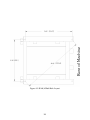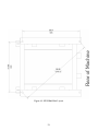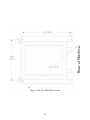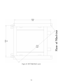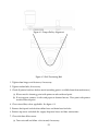
1
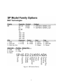
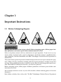
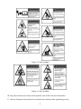
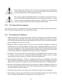
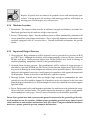
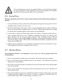
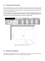
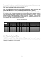
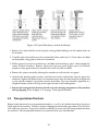
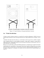
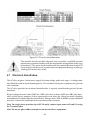
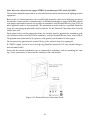
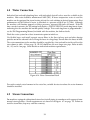
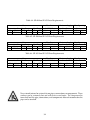
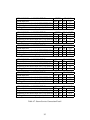
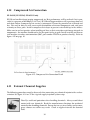
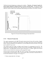
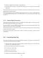
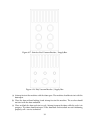
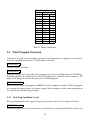
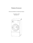
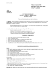
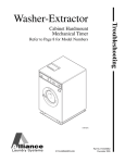
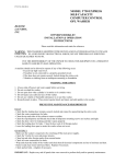
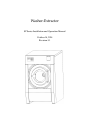
Washer-Extractor
SP Series Installation and Operation Manual
October 14, 2014
Revision 3.1
Contents
1
2
Important Instructions
2
1.1
Before Attempting Repairs . . . . . . . . . . . . . . . . . . . . . . . . . . . . . . . . . .
2
1.2
Parts Ordering Information . . . . . . . . . . . . . . . . . . . . . . . . . . . . . . . . .
3
1.2.1
Nameplate Location . . . . . . . . . . . . . . . . . . . . . . . . . . . . . . . . .
3
1.3
Key Symbols . . . . . . . . . . . . . . . . . . . . . . . . . . . . . . . . . . . . . . . . . .
3
1.4
Safety Information . . . . . . . . . . . . . . . . . . . . . . . . . . . . . . . . . . . . . .
3
1.5
Installation and Operational Safety Instructions . . . . . . . . . . . . . . . . . . . . .
4
Introduction
7
2.1
Customer Service . . . . . . . . . . . . . . . . . . . . . . . . . . . . . . . . . . . . . . .
8
2.2
Replacement Parts . . . . . . . . . . . . . . . . . . . . . . . . . . . . . . . . . . . . . .
8
2.3
Theory of Operation . . . . . . . . . . . . . . . . . . . . . . . . . . . . . . . . . . . . .
8
3
General Specifications
10
4
Installation
13
4.1
Receiving Inspection . . . . . . . . . . . . . . . . . . . . . . . . . . . . . . . . . . . . .
13
4.2
Safety Checklist . . . . . . . . . . . . . . . . . . . . . . . . . . . . . . . . . . . . . . . .
13
4.2.1
Operator Safety . . . . . . . . . . . . . . . . . . . . . . . . . . . . . . . . . . . .
14
4.2.2
Safe Operation Environment . . . . . . . . . . . . . . . . . . . . . . . . . . . .
15
4.2.3
Environmental Conditions . . . . . . . . . . . . . . . . . . . . . . . . . . . . .
15
4.2.4
Machine Location . . . . . . . . . . . . . . . . . . . . . . . . . . . . . . . . . . .
16
4.2.5
Input and Output Services . . . . . . . . . . . . . . . . . . . . . . . . . . . . . .
16
4.2.6
Inverter Drive . . . . . . . . . . . . . . . . . . . . . . . . . . . . . . . . . . . . .
17
i
4.2.7
5
Machiner Misuse . . . . . . . . . . . . . . . . . . . . . . . . . . . . . . . . . . .
17
4.3
Dimensional Clearances . . . . . . . . . . . . . . . . . . . . . . . . . . . . . . . . . . .
18
4.4
Machine Foundation . . . . . . . . . . . . . . . . . . . . . . . . . . . . . . . . . . . . .
18
4.4.1
Mounting Bolt Installation . . . . . . . . . . . . . . . . . . . . . . . . . . . . . .
19
4.4.2
Mounting Bolt Location . . . . . . . . . . . . . . . . . . . . . . . . . . . . . . .
27
4.5
Transportation Brackets . . . . . . . . . . . . . . . . . . . . . . . . . . . . . . . . . . .
28
4.6
Drain Installation . . . . . . . . . . . . . . . . . . . . . . . . . . . . . . . . . . . . . . .
29
4.7
Electrical Installation . . . . . . . . . . . . . . . . . . . . . . . . . . . . . . . . . . . . .
30
4.8
Water Connection . . . . . . . . . . . . . . . . . . . . . . . . . . . . . . . . . . . . . . .
33
4.9
Steam Connection . . . . . . . . . . . . . . . . . . . . . . . . . . . . . . . . . . . . . . .
33
4.10 Compressed Air Connection . . . . . . . . . . . . . . . . . . . . . . . . . . . . . . . . .
36
4.11 External Chemical Supplies . . . . . . . . . . . . . . . . . . . . . . . . . . . . . . . . .
36
4.11.1 Chemical Connection . . . . . . . . . . . . . . . . . . . . . . . . . . . . . . . .
37
4.11.2 Chemical Signal Connections . . . . . . . . . . . . . . . . . . . . . . . . . . . .
38
4.12 Control Function Test . . . . . . . . . . . . . . . . . . . . . . . . . . . . . . . . . . . . .
38
Operation
41
5.1
Door Lock Operation . . . . . . . . . . . . . . . . . . . . . . . . . . . . . . . . . . . . .
41
5.1.1
Opening and Closing the Door . . . . . . . . . . . . . . . . . . . . . . . . . . .
41
5.1.2
Periodic Maintenance . . . . . . . . . . . . . . . . . . . . . . . . . . . . . . . .
42
5.2
Machine Loading . . . . . . . . . . . . . . . . . . . . . . . . . . . . . . . . . . . . . . .
42
5.3
Wash Program Execution . . . . . . . . . . . . . . . . . . . . . . . . . . . . . . . . . . .
43
5.3.1
End Step Condition: Level . . . . . . . . . . . . . . . . . . . . . . . . . . . . . .
43
5.3.2
End Step Condition: Temperature . . . . . . . . . . . . . . . . . . . . . . . . .
44
5.3.3
End Step Condition: Time . . . . . . . . . . . . . . . . . . . . . . . . . . . . . .
44
5.3.4
Single Step Execution . . . . . . . . . . . . . . . . . . . . . . . . . . . . . . . .
44
5.3.5
Partial Program . . . . . . . . . . . . . . . . . . . . . . . . . . . . . . . . . . . .
45
5.3.6
Displaying the Current Program and Step . . . . . . . . . . . . . . . . . . . . .
45
5.3.7
Soak . . . . . . . . . . . . . . . . . . . . . . . . . . . . . . . . . . . . . . . . . .
45
5.3.8
Advance . . . . . . . . . . . . . . . . . . . . . . . . . . . . . . . . . . . . . . . .
45
ii
5.3.9
6
7
8
Halting a Program . . . . . . . . . . . . . . . . . . . . . . . . . . . . . . . . . .
45
5.3.10 Water Level Refresh . . . . . . . . . . . . . . . . . . . . . . . . . . . . . . . . .
45
5.3.11 Unbalance . . . . . . . . . . . . . . . . . . . . . . . . . . . . . . . . . . . . . . .
46
5.3.12 Power Failure . . . . . . . . . . . . . . . . . . . . . . . . . . . . . . . . . . . . .
46
5.3.13 End of Program . . . . . . . . . . . . . . . . . . . . . . . . . . . . . . . . . . . .
46
5.3.14 Malfunction Alarms . . . . . . . . . . . . . . . . . . . . . . . . . . . . . . . . .
46
5.3.15 Maintenance Alarm . . . . . . . . . . . . . . . . . . . . . . . . . . . . . . . . .
47
Maintenance
49
6.1
Daily . . . . . . . . . . . . . . . . . . . . . . . . . . . . . . . . . . . . . . . . . . . . . .
49
6.1.1
Beginning of Day . . . . . . . . . . . . . . . . . . . . . . . . . . . . . . . . . . .
49
6.1.2
End of Day . . . . . . . . . . . . . . . . . . . . . . . . . . . . . . . . . . . . . .
50
6.2
Weekly . . . . . . . . . . . . . . . . . . . . . . . . . . . . . . . . . . . . . . . . . . . . .
50
6.3
Monthly . . . . . . . . . . . . . . . . . . . . . . . . . . . . . . . . . . . . . . . . . . . .
50
6.4
Quarterly . . . . . . . . . . . . . . . . . . . . . . . . . . . . . . . . . . . . . . . . . . . .
51
6.5
Care of Stainless Steel . . . . . . . . . . . . . . . . . . . . . . . . . . . . . . . . . . . . .
53
Service & Parts
55
7.1
Service . . . . . . . . . . . . . . . . . . . . . . . . . . . . . . . . . . . . . . . . . . . . .
55
7.2
Parts . . . . . . . . . . . . . . . . . . . . . . . . . . . . . . . . . . . . . . . . . . . . . .
55
Decommisioning
56
iii
Figure 1: SP Product Family
1
Chapter 1
Important Instructions
1.1
Before Attempting Repairs
Moving parts can cause serious injury or death. Before attempting repairs, follow proper shutdown procedures and remove power before commencement of service.
Safety is of primary concern with any maintenance or repair operation. If you are in any way
unsure of how to proceed with a repair or adjustment, consult this manual, a qualified maintenance technician, your local distributor, or the B&C Technologies Technical Service Department at
850-249-2222.
Only trained and experienced personnel should attempt maintenance or repair work on this equipment. Follow all safety procedures including lock-out/tag-out procedures carefully. Ensure that
any loose fitting clothing or jewelry is tucked in or not worn to avoid being pulled into the machine. Remember, the machine has no brain - you must use your own.
Before attempting repairs, follow proper shutdown procedures and remove power before commencement of service.
Never attempt to clean or service any area of the machine without removing power at the main
disconnect.
Read, follow, and obey these safety rules! The B&C Technologies Technical Service Department
2
is available to answer any questions you may have about the operation and servicing of your
machine. Please call with any questions or concerns about the operation of your machine.
1.2
Parts Ordering Information
If you require literature or spare parts, please contact your local distributor. If a local distributor
is unavailable, you may contact B&C Technologies directly at (850) 249-2222 for the name of your
nearest parts dealer.
For technical assistance in the United States, contact B&C Technologies:
(850) 249-2222 Phone
(850) 249-2226 FAX
[email protected]
www.bandctech.com
1.2.1
Nameplate Location
When contacting B&C Technologies about your equipment, please make note of the model and
serial number, located on the nameplate as shown in figure 1.1.
1.3
Key Symbols
Anyone operating or servicing this machine must follow the safety rules in this manual. Particular attention must be paid to the DANGER, WARNING, and CAUTION blocks which appear
throughout the manual and shown in figures 1.2 on page 5 and 1.3 on page 5.
1.4
Safety Information
Installation Notice: For personal safety and for proper operation, the machine must be grounded
in accordance with state and local codes and in the USA in accordance with the National Electric
Code, article 250-96. Elsewhere, the equipment should be grounded in accordance with ANSI/NFPA
70, or the Canadian Electrical Code, CSA C22.1. The ground connection must be to a proven earth
ground, not to conduit or water pipes.
3
Figure 1.1: Serial Decal
1.5
Installation and Operational Safety Instructions
1. Read all instructions prior to operating this equipment.
2. Ensure that the equipment is properly grounded before applying power and operation commences.
3. Do not allow children to play in or around or operate this equipment.
4. Check the operation of all safety interlocks at the start of every shift. If the interlocks do not
stop the equipment immediately, the machine must be removed from service. Notify your
immediate supervisor, and do not operate the machine.
5. Never attempt to service the machine while it is running. Never reach over, under, around, or
behind any safety device, or into any area near moving parts or hot surfaces without shutting
off power and allowing the machine to adequately cool.
6. Read, understand, and follow all safety instructions. Do not come close to moving parts and
hot surfaces. Do not wear loose clothing, jewelry, neckties, or any other garment that could
be come caught in the machine while operating or near the machine.
7. Only a qualified technician should attempt to service or repair the machine.
8. Do not install the machine in an area where it could be exposed to water or weather.
9. Do not alter or tamper with the control system.
4
Figure 1.2: Key Symbols
Figure 1.3: Key Symbols
10. Keep the interior and exterior of the machine clean of lint, dirt, dust and debris.
11. Always disconnect the electrical service from the machine before performing service.
5
12. This machine must be installed according to the installation instructions. All utility connections must comply with state and local codes and must be made by a licensed installer where
required.
6
Chapter 2
Introduction
The B&C SP Series is the professional freestanding washer-extractor series of machines from B&C
Technologies. It is an open pocket washer-extractor with a large door opening for easy and quick
loading and unloading. It has been developed for the on premise market, and is suitable for
commercial laundries, hotel and other places where laundry might be processed
The design allows for top performance at lowest possible operation cost and investment. The
flexible electronic control center ensures that maximum productivity is obtained.
The SP series utilizes high quality material, such as 304 (18/8) stainless steel in vital parts in contact
with the wash solution. It has a stainless steel cabinet for long life with easily removable panels.
The key advantages of this series are the simplicity of the microprocessor and the electronic AC
drive system, which utilizes only one motor. The system allows for washing and extraction at
any speed and mechanical action to suit any textile fiber used today and tomorrow. A built in
suspension system isolate objectionable vibrations and the high speed final extraction saves time
and energy in the finishing operation.
A single compartment supply dispenser for powder and liquid detergents is standard (five compartment optional) and the machine is designed to accept the connection of 8 additional external
chemical lines and pumps.
The SP series is also prepared to accept the connection of water reuse systems. These systems can
be installed separate or on top of the machine. They are available in either single or dual tanks
for maximum savings of water up to 40%. The tanks can be equipped with or without steam or
electrical heat depending on installation and operation. The water reuse system is programmable
by the machines electronic control center.
Wetcleaning and Ozone integration are also possible with the SP series, making them the most
flexible machine available today.
7
2.1
Customer Service
For technical assistance:
In the United States
Phone: (850)-249-2222
FAX: (850) 249-2226
e-mail: [email protected]
Web: www.bandctech.com
2.2
Replacement Parts
In the event that literature or replacement parts are required, contact the local distributor of the
equipment, or contact B&C Technologies at the above phone numbers/internet addresses.
2.3
Theory of Operation
The B&C SP models use a single-speed motor to drive the cylinder via V-belts in all speeds. The
cylinder is supported by two spherical roller bearings located in a cast steel bearing housing or
split pillow block housings made of cast steel.
The motor is controlled by the computer control located in the front and the AC inverter drive
located in the rear panel. Any speed can be programmed for any wash cycle. Some speed ranges
are blocked out for programming due to safety reasons. These speed ranges are the ones that
the machine cannot operate at due to its spring or suspension resonance. This speed range is not
important and normally speeds for wash or extraction are not selected within this range. Any wash
speed in the range of 3-50 RPM and extraction speeds 150-Maximum RPM can be programmed.
Further any reversing action can be programmed. Normal reversing action is 16 seconds forward,
pause for 4 seconds, and 16 seconds reverse. Any temperature between 70F to 200F (20-95C) can
be programmed. Any water level in the range of the machine parameters can be programmed in
centimeters. The computer will automatically provide safety levels for steam injections and door
operations.
Water entry into the machine is through an air gap vacuum breaker utilizing electro-magnetic water valves controlled by the computer. By utilizing the air gap vacuum breaker, backflow into the
water supply is impossible. The computer also controls the drain, supply dispenser, any external
liquid supplies, steam injection and any other vital functions of the wash program. The computer
can even record cycles and data of importance that could be used for maintenance purpose.
The steam, if installed, is injected in the bottom of the shell via a steam injector. The steam is
controlled by a steam valve that is programmed by the EL6 / FM7 micro computer.
The cylinder is perforated, allowing water to pass through and drain from within during drain
and extract steps. Lifting ribs inside the cylinder lift the load from the wash solution and allow
the load to tumble and falling back into the solution when the load reaches the approximate 10-11
8
oclock or 1-2 oclock positions. This mechanical action removes soil from the fabric. Furthermore,
the lifters are perforated on the top so that water can cascade over the goods and wet them quickly.
This reduces water consumption as water is picked up at the cylinders lowest point and lifted and
splashed over the goods at the highest point as the cylinder rotates.
A stainless steel door is provided for loading and unloading. A door lock system prevents operation of the machine when the door is open. The door is locked during operation utilizing a
solenoid and a manual latch for safety reasons. The door lock is provided with a magnetic sensor
to indicate that the machine is locked and provide for start of the machine when the door is closed
and locked.
The AC drive, contactor, circuit overload protectors, input power supply connections, external
supply connections, and control transformer are behind a cover on the rear of the machine.
The supply dispenser is mounted on the front of the machine and is accessed by opening the cover
door. Supplies, both liquid and powder, may be added by pulling the dispenser cups out and
placing the appropriate supply in each. Supplies are flushed into the machine at the proper time
in the cycle, controlled by the microcomputer.
Holes are provided at the rear of the machine for connection to an external, central liquid supply
unit. Electrical connections are provided for the liquid supply unit on a terminal strip inside the
rear control module.
9
Chapter 3
General Specifications
10
MODEL
Maximum Capacity
Overall Dimensions
A - Width
B - Depth
C - Height
Wash Cylinder Information
Cylinder Diameter
Cylinder Depth
Cylinder Volume
Motor
Size
Cylinder Speeds (Programmable)
Wash
Distribution
Intermediate Extract
High Extract 1
High Extract 2
High Extract 3
Door Opening
Door Opening Diameter
Height to Bottom of Door
Drain System
Overflow Size
Drain Outlet Size
Number of Drains
Steam Inlet
Connection Size
Water Inlet
Connection Size
Number of Inlets
Chemical Supply System
Dry Chemical Compartments
Liquid Supply Connections
Liquid Supply Connection Size
Weight and Shipping Information
Net Weight
Shipping Weight
Electrical Service
208-240VAC, 50/60HZ, 1PH
208-240VAC, 50/60HZ, 3PH
380-460VAC, 50/60HZ, 3PH
208-240VAC, 50/60HZ, 3PH Heat
380-460VAC, 50/60HZ, 3PH Heat
Metric
kg
US
lbs
SP-45
20.5
45.0
SP-50
22.7
50.0
SP-65
29.6
65.0
SP-75
34.1
75.0
mm
mm
mm
in
in
in
925
1093
1466
36.4
43.0
57.7
925
1153
1466
36.4
45.4
57.7
1003
1231
1615
39.5
48.5
63.6
1003
1306
1615
39.5
51.4
63.6
mm
mm
liters
in
in
cu ft
680
515
187
26.8
20.3
6.6
680
575
209
26.8
22.6
7.4
789.94
558.8
274
31.1
22.0
9.7
789.94
633.73
311
31.1
25.0
11.0
kW
HP
2.2
3
2.2
3
3.75
5
3.75
5
G
G
G
G
G
G
rpm
rpm
rpm
rpm
rpm
rpm
0.8
2
150
200
250
350
46
73
829
725
811
960
0.8
2
150
200
250
350
46
73
829
725
811
960
0.8
2
150
200
250
350
42
67
583
673
753
890
0.8
2
150
200
250
350
42
67
583
673
753
890
mm
mm
in
in
370
655
14.6
25.8
370
655
14.6
25.8
450
740
17.7
29.1
450
740
17.7
29.1
mm
mm
Standard
in
in
Optional
38.1
60.452
1
1.5
2.38
2
38.1
60.452
1
1.5
2.38
2
38.1
76.2
1
1.5
3
2
38.1
76.2
1
1.5
3
2
NPT
1/2”
NPT
Standard
Optional
Standard
Optional
Standard
Optional
NPT
1/2”
3/4”
1/2”
3/4”
1/2”
3/4”
3/4”
2
3
2
3
2
3
2
3
1
8
5
12
1
8
5
12
1
8
5
12
1
8
5
12
1/2”
1/2”
1/2”
1/2”
kg
kg
lb
lb
591
610
1300.2
1342
615
634
1353
1394.8
660
720
1452
1584
687
747
1511.4
1643.4
Amps
Amps
Amps
Amps
Amps
Breaker
Breaker
Breaker
Breaker
Breaker
8
5
3
48
24
15
15
15
60
30
9
6
3
49
25
15
15
15
60
30
14
8
4
52
26
15
15
15
60
30
14
9
4
53
27
15
15
15
60
30
Table 3.1: SP Series General Specifications
11
MODEL
Maximum Capacity
Overall Dimensions
A - Width
B - Depth
C - Height
Wash Cylinder Information
Cylinder Diameter
Cylinder Depth
Cylinder Volume
Motor
Size
Cylinder Speeds (Programmable)
Wash
Distribution
Intermediate Extract
High Extract 1
High Extract 2
High Extract 3
Door Opening
Door Opening Diameter
Height to Bottom of Door
Drain System
Overflow Size
Drain Outlet Size
Number of Drains
Steam Inlet
Connection Size
Water Inlet
Connection Size
Number of Inlets
Chemical Supply System
Dry Chemical Compartments
Liquid Supply Connections
Liquid Supply Connection Size
Weight and Shipping Information
Net Weight
Shipping Weight
Electrical Service
208-240VAC, 50/60HZ, 1PH
208-240VAC, 50/60HZ, 3PH
380-460VAC, 50/60HZ, 3PH
208-240VAC, 50/60HZ, 3PH Heat
380-460VAC, 50/60HZ, 3PH Heat
Metric
kg
US
lbs
SP-110
50.0
110.0
SP-135
61.4
135.0
SP-165
75.0
165.0
SP-195
88.7
195.0
mm
mm
mm
in
in
in
1204
1395
1805
47.4
54.9
71.1
1300
1600
1765
51.2
63.0
69.5
1538
1730
1826
60.6
68.1
71.9
1602
1784
1894
63.1
70.2
74.6
mm
mm
liters
in
in
cu ft
940
690
479
37.0
27.2
16.9
1067
660
590
42.0
26.0
20.8
1092
757
709
43.0
29.8
25.0
1174
780
844
46.2
30.7
29.8
kW
HP
7.5
10
7.5
10
11
15
15
20
G
G
G
G
G
G
rpm
rpm
rpm
rpm
rpm
rpm
0.8
2
150
200
250
350
39
62
535
618
690
817
0.8
2
150
200
250
350
36
64
360
515
600
767
0.8
2
150
200
250
350
36
64
360
480
600
725
0.8
2
150
200
250
350
35
62
380
465
580
700
mm
mm
in
in
508
800
20.0
31.5
509
820
20.0
32.3
635
830
25.0
32.7
635
870
25.0
34.3
mm
mm
Standard
in
in
Optional
38.1
76.2
1
1.5
3
2
63.5
101.6
1
2.5
4
2
63.5
102
1
2.5
4
2
63.5
101.6
1
2.5
4
2
NPT
3/4”
NPT
Standard Optional
Standard Optional
Standard Optional
NPT
1”
1”
1”
1”
2
3
2
1
8
5
12
8
1/2”
1-1/4”
1”
3
2
12
8
5
1-1/4”
3
2
12
8
3
5
1/2”
5
1/2”
12
1/2”
kg
kg
lb
lb
1068
1091
2349.6
2400.2
1790
1809
3938
3980
1910
1955
4202
4301
2090
2135
4598
4697
Amps
Amps
Amps
Amps
Amps
Breaker
Breaker
Breaker
Breaker
Breaker
31
18
9
78
39
40
20
15
80
40
n/a
26
13
n/a
n/a
n/a
60
20
n/a
n/a
n/a
32
16
n/a
n/a
n/a
40
25
n/a
n/a
n/a
58
29
n/a
n/a
n/a
60
30
n/a
n/a
Table 3.2: SP Series General Specifications
12
Chapter 4
Installation
4.1
Receiving Inspection
Upon receipt of the equipment, visually inspect for shipping damage and note any damage with
the carrier before signing the shipping receipt, or advise the carrier of the damage as soon as it is
noted.
If damage is discovered, a written claim must be filed with the carrier as soon as possible.
Note: Warranty is VOID unless the equipment is installed according to instructions. The installation must comply with the minimum requirements listed in this manual. All national, state and
local codes must be followed including but not limited to gas, electrical, plumbing and HVAC.
Due to various requirements, statutory codes should be well understood before installation commences.
Important: The machine should be transported and handled in an upright position.
4.2
Safety Checklist
Before Initial start up of a B&C free-standing washer extractor perform the following safety check:
1. Make sure all electrical and plumbing connections have been made in accordance with applicable codes and regulations.
2. Make sure the machine is grounded electrically.
3. Make sure the machine has flexible water fill and drain connections of the correct size, length
and type, with no kinks, and that they are securely attached and/or clamped.
4. Make sure the transport brackets have been removed.
Before machine is placed in operation, the door safety interlock must be checked for proper operation as follows:
13
Before servicing any equipment, make certain it is disconnected from the electrical
power source. Never allow operation of the machine when any safety device is
malfunctioning. Never bypass safety devices.
Never insert hands or objects into basket until it has completely stopped. Doing
so could result in serious injury.
1. When the washer is energized electrically and in operation, the loading door must be locked
in the closed position. Verify this by attempting to open the loading door when the machine
is operating. If necessary, check the door safety interlock and sensors for proper operation.
Consult the service manual, or call a qualified service technician if necessary.
2. When the washers loading door is open, it should not be possible to start the machine. Verify
this by attempting to start the washer with the door open. Also, close the door without
locking it and verify that it is not possible to start the machine with the door not locked. If
necessary, check the door lock sensors for proper operation,. Consult the service manual, or
call a qualified service technician. If additional information is required, contact your local
distributor or call the manufacturer of the machine.
• To provide personal safety and keep the machine in proper working order, follow all maintenance and safety procedures presented in this manual. If questions regarding safety arise.
Contact the factory immediately.
• Use factory authorized spare parts to avoid safety hazards.
4.2.1
Operator Safety
To ensure the safety of machine operators the following maintenance checks must be performed
daily.
1. Prior to operating the machine, verify that all warning signs are present and legible. Missing
or illegible signs must be replaced immediately. Make certain that spares are available.
2. Check door interlock before starting operation of the machine, see safety check list.
3. Do not attempt to operate the machine if any of the following conditions are present:
(a) The door does not remain securely locked during the entire cycle.
(b) Excessively high water level is evident.
(c) Machine is not connected to a properly grounded circuit.
Do not bypass any safety devices in the machine.
14
Never operate the machine with a bypassed or disconnected out-of-balance
switch. Operating the machine with severe out-of-balance loads could result
in personal injury and serious equipment damage.
Do not place volatile or flammable fluids in any machine. Do not clean the machine with volatile or flammable fluids such as acetone, lacquer thinners, enamel
reducers, carbon tetrachloride, gasoline, benzene, naphtha, etc. Doing so could
result in serious personal injury and/or damage to the machine.
4.2.2
Safe Operation Environment
Safe operation requires an appropriate operating environment for both the operator and the machine. If questions regarding safety arise, contact the factory.
4.2.3
Environmental Conditions
1. Ambient temperature. Water in the machine will freeze at temperatures of 32F (0C) or below.
Temperatures above 120 F (50C) will result in more frequent motor overheating and, in some
cases, malfunction or premature damage to solid state devices that are used in the machines.
Special cooling devices may be necessary.
2. Humidity. Relative humidity above 90% may cause the machines electronics or motors to
malfunction or may trip the ground fault interrupter. Corrosion problems may occur on
some metal components. If the relative humidity is below 30% belts and rubber hoses may
eventually develop dry rot. This condition can result in hose leaks, which may cause hazards
external to the machine in conjunction with adjacent electrical equipment.
3. Ventilation. The need for make-up air openings for such laundry room accessories as dryers , ironers, water heaters, etc. must be evaluated periodically. Louvers, screens, or other
separating devices may reduce the available air opening significantly.
4. Radio Frequency Emissions. A filter is available for machines in installations where floor
space is shared with equipment sensitive to radio frequency emissions. All machines that are
shipped to CE countries are equipped with this filter and comply with the EMI regulations.
5. Elevation. If the machine is to be operated at elevations over 3280 feet (1000 meters) above sea
level, pay special attention to water levels and electronic settings ( particularly temperature)
or desired result may not be achieved.
6. Chemicals. Keep stainless steel surfaces free of chemical residues to avoid corrosion.
7. Water damage. Do not spray the machine with water. Short circuiting and serious damage
may result. Repair immediately all seepage due to faulty gaskets, etc.
15
Replace all panels that are removed to perform service and maintenance procedures. Do not operate the machine with missing guards or with broken or
missing parts. Do not bypass any safety devices.
4.2.4
Machine Location
1. Foundation. The concrete floor must be of sufficient strength and thickness to handle the
floor loads generated by the machine at high extract speeds.
2. Service/ Maintenance Space. Provide sufficient space to allow comfortable performance of
service procedures and routine maintenance. This is especially important in connection with
machines equipped with AC inverter drives. Consult installation instructions for specific
details.
4.2.5
Input and Output Services
1. Water pressure. Best performance will be realized if water is provided at a pressure of 30-85
psi (2.0-5.7 bar). Although the machine will function properly at lower pressure, increased
fill time will occur. Water pressure higher than 120 psi (8.0 bar) may result in damage to
machine plumbing. components failure (s) and personal injuries.
2. Optional Steam heating pressure. Best performance will be realized if steam pressure is
provided at a pressure of 30-80 psi (2.0-5.4 bar). Steam pressure higher than 125 psi (8.5 bar)
may result in damage to steam components and may cause personal injuries. For machines
equipped with optional steam heat, install piping in accordance with approved commercial
steam practices. Failure to install a steam filter may void the warranty.
3. Drainage System. Provide drain lines or troughs large enough to accommodate the total
quantity of water that could be dumped if all machines on the site drained at the same time
from the highest attainable level. If drain troughs are used, they should be covered to support
light foot traffic
4. Power. For personal safety and for proper operation, the machine must be grounded in accordance with state and local codes. The ground connection must be to a proven earth ground,
not to conduits or water pipes. An easy-access disconnect switch should be provided.
Ensure that a ground wire from a proven earth ground is connected to the ground lug in the electrical junction box on this machine. Without proper grounding personal injury from electrical
shock could occur and machine malfunctions may be evident. Computer-controlled machines
must have a proper ground to prevent computer malfunctions.
16
Always disconnect power and water supplies before a service technician performs
any service procedure. Where applicable, steam and/or compressed air supplies
should also be disconnected before service is performed.
4.2.6
Inverter Drive
Machines equipped with AC drives require special attention with regard to the operating environment.
1. An especially dusty or linty environment will require more frequent cleaning of the AC drive
cooling fan filter and of the AC drive itself.
2. Power line fluctuations from sources such as an uninterruptible power supplies (UPS) can
adversely affect machines equipped with the AC drive. Proper suppression devices should
be utilized on the incoming power to the machine to avoid problems.
3. A clean power supply free from voltage spikes and surges is absolutely essential for machines equipped with the AC drive. Nonlinear inconsistencies (peaks and valleys) in the
power can cause the AC drive to generate nuisance errors. If voltage is above 230V for
200 V installations or above 460V for 400V installations, a buck/boost transformer is recommended. If voltage is above 240V or 480V, a buck/boost transformer is required unless the
factory advises differently.
4. Sufficient space to perform service procedures and routine preventive maintenance is especially important for machines equipped with AC drives.
4.2.7
Machiner Misuse
Even though this machine is an atmospheric vessel, never use it for any purpose other than
washing fabrics.
1. Never wash petroleum-soaked rags in the machine. This could result in an explosion.
2. Never wash machine parts or automotive parts in the machine. This could result in serious
damage to the wash cylinder.
3. Never stone wash in the machine. It could wear the wash cylinder and serious damage might
occur to the machine.
4. Never use the machine for dyeing nor with harsh chemicals that can cause corrosion and
other health hazards.
5. Never allow children to play on or around this machine. Death or serious injury can result
if children become trapped in the machine. Do not leave children unattended while the
machine door is open. These cautions apply to animals as well.
17
4.3
Dimensional Clearances
When installing the washer-extractor, it is important to allow adequate clearance on all sides of the
machine. When multiple machines are installed, it is important to allow for the specified minimum
clearances between machines. The following table shows recommended minimum clearances for
the various freestanding models.
Note: The dimensions are approximate and subject to normal manufacturing tolerances. If
exact dimensions are required for construction purposes, request certified drawings from the
factory. We reserve the right to make changes at any time without notice.
Figure 4.1: Minimum Service Clearances
4.4
Machine Foundation
Thoroughness of details must be stressed with all foundation work to insure a stable unit installation, eliminating possibilities of excessive vibrations during extraction.
18
For a successful installation, a smooth level surface, so that the entire base of the machine is supported and rests on the mounting surface, is absolutely requried.
Note: Do not support the machine on only four points.
Note: Freestanding washer-extractors do not require anchoring bolts unless specified by state
or local codes. However it is always recommended that the machines be anchored.
Special care must be taken when machines are installed on an upper floor. Make sure that the floors
are designed to carry the static and dynamic loads of the machines. Further vibrations should be
taken into consideration so that the machine does not create vibrations in the building. Static and
dynamic loads on the floor or foundation are shown in the figure 4.1 on page 19. This table can
be used as reference when designing floors and foundations. See the figures beginning on page
20 for mounting bolt layout measurement and pattern.
Table 4.1: Floor Load Data
SP-45
SP-50
SP-65
SP-75
SP-110
SP-135
SP-165
SP-195
4.4.1
Static floor load
kN
lbs
7.28
1635
7.64
1718
8.41
1890
8.9
2001
13.34
2999
14.88
3344
22.64
5089
24.53
5514
Static pressure
kN/m2 lbs-ft2
7.21
150
7.17
150
6.8
142
6.8
142
7.95
166
7.15
149
8.5
178
8.59
179
Dynamic floor load
kN
lbs
2.8
631
3.1
701
4
909
4.7
1048
6.9
1542
8.4
1893
9.4
2116
11.1
2505
Dynamic pressure
kN/m2
lbs-ft2
2.8
58
2.9
61
3.3
68
3.6
74
4.1
85
4
85
3.5
74
3.9
81
Dynamic Frequency
Hz
16
16
14.8
14.8
13.6
12.8
12.1
11.7
Mounting Bolt Installation
All SP Machines use 1/2-13 bolts. Embed the bolts in 3500 psi reinforced concrete with a minimum
of 4”’ thickness. The threaded end of the bolt should extend 2 inches from the surface of the floor.
Grouting is recommended, but not required.
19
Figure 4.2: SP-40/45 Bolt Hole Layout
20
Figure 4.3: SP-50 Bolt Hole Layout
21
Figure 4.4: SP-60/65 Bolt Hole Layout
22
Figure 4.5: SP-75 Bolt Hole Layout
23
Figure 4.6: SP-100/110 Bolt Hole Layout
24
Figure 4.7: SP-130/135 Bolt Hole Layout
25
Figure 4.8: SP-155/165 Bolt Hole Layout
26
Figure 4.9: SP-185/195 Bolt Hole Layout
4.4.2
Mounting Bolt Location
All B&C washer-extractors should be secured by the use of machinery anchor bolts. High strength
machinery anchors should be embedded in 3500 psi (24000 N/m2) reinforced concrete. For detailed information regarding the machine anchor bolt, see the instructions included with the anchor bolts themselves. The information provided is just an example. Ensure that the concrete is
fully cured before proceeding.
Place the machine adjacent to the foundation. Do not attempt to move it by pushing on the sides.
27
Figure 4.10: Typical Machinery Anchor Installation
1. Remove the wood skid by unscrewing the carriage bolts holding it to the bottom frame of
the machine.
2. Carefully place the machine over the anchor bolts. Raise and level it 1/2 inch above the floor
on four points, using spacers that can be removed.
3. Fill the spaces between the machine base and floor with machinery grout. Grout completely
under all frame members. Remove front panel and rear panel to gain access to all frame
members. Force grout under the machine base until all voids are filled.
4. Remove the spacers carefully, allowing the machine to settle into the wet grout.
5. Attached the mounting bolt washers and lock nuts to the anchor bolts after the grout has
hardened. Tighten the lock nuts by even increments-one after the other-until all are tightened
evenly and the machine is fastened securely to the floor. The nuts should be tightened in a
diagonal fashion, which will help ensure equal tension at all anchor points.
6. Remove the transportation brackets which secure the moving components of the machine
during shipping. Refer to figure 4.11 on page 29 for typical locations.
4.5
Transportation Brackets
Remove both front and rear transportation brackets, as well as the bracket located on the lower
inside right of the machine. Failure to remove shipping brackets before operation of the SP series
will void your warranty. Inspect the machine carefully to ensure that all transportation brackets
are removed. All transportation brackets are painted red for easy identification.
28
Figure 4.11: Typical Machinery Transportation Bracket Location
4.6
Drain Installation
A drain system of adequate capacity is essential to the machine performance. Ideally the water
should empty through a 4 inch vented pipe directly into a sump or floor drain. See figure 4.12 on
30.
A flexible connection must be made to a vented drain system to prevent an airlock or siphon
effect. If proper drain size is not available or practical, a surge tank is required. A surge tank in
conjunction with a sump pump should be used when gravity drainage is not possible, such as in
below-ground-level installations.
Before any deviation from specified installation procedures is attempted, the customer or installer
should contact the manufacturer. Increasing the drain hose length, installing elbows, or causing
bends will decrease drain flow rate and increase drain time, impairing machine performance. If
the drain arrangement is inadequate, the machine will not extract and will not discharge water
properly.
29
Figure 4.12: Drain System Information
This machine must be installed, adjusted, and serviced by a qualified electrical
maintenance personnel familiar with the construction and operation of this type
of machinery. They must also be familiar with the potential hazards involved. If
this warning is not observed, personal injury or equipment damage resulting in
voiding the warranty may result.
4.7
Electrical Installation
The AC drive requires a clean power supply free from voltage spikes and surges. A voltage monitor should be used to check incoming power. The customers local power company may provide
such a monitor.
The AC drive provides for an internal circuit breaker. A separate circuit breaker governs the control circuit.
If input voltage measures above 230V for a 200V class drive or above 460V for a 400V class drive,
either ask the power company if their representative can lower the voltage or install a bucking
transformer kit available from the manufacturer. Voltages above 250V and 490V require additional
measures. Contact the distributor or the manufacturer for assistance.
Note: For single phase operation (up to SP-110 only), connect input power to R and S, leaving
the T terminal open.
Note: Do not use phase adders (roto-phase) on inverter driven equipment!
30
If controlling the AC drive with a parameter unit, the machines computer and
its safety features are bypassed. This could allow the basket to rotate at high
speeds with the door open. When using a parameter unit to control the AC
drive, a large sign should be placed on the front of the machine warning people
of the imminent danger.
Never touch terminals or components of the AC drive unless power is disconnected and the ”‘CHARGE”’ indicator LED is off. The AC drive retains potential
deadly voltage for some time after the power is disconnected. There are no userserviceable parts inside the AC drive. Tampering with the drive will void the
warranty.
Dangerous voltage are present in the electrical control boxes and at the motor
terminals. Only qualified personnel familiar with electrical test procedures, test
equipment, and safety precautions should attempt adjustments and troubleshooting. Disconnect power from the machine before removing the control box cover,
and before attempting any service procedures.
Table 4.2: 200V Electrical Service Requirements
Machine
SP-40 / 45
SP-50
SP-60 / 65
SP-75
SP-100 / 110
SP-130 / 135
SP-155 / 165
SP-185 / 195
200-230V, 1 PH
200-230V, 3 PH
Max Amps Breaker
Wire Size
Max Amps Breaker
Wire Size
8
15
14ga / 1.6mm
5
15
14ga / 1.6mm
11
15
14ga / 1.6mm
6
15
14ga / 1.6mm
14
15
14ga / 1.6mm
8
15
14ga / 1.6mm
14
15
14ga / 1.6mm
9
15
14ga / 1.6mm
31
40
10ga / 2.5mm
18
20
14ga / 1.6mm
N/A
26
30
10ga / 2.5mm
N/A
32
40
10ga / 2.5mm
N/A
58
60
6ga / 4mm
Table 4.3: 400V Electrical Service Requirements
Machine
SP-40 / 45
SP-50
SP-60 / 65
SP-75
SP-100 / 110
SP-130 / 135
SP-155 / 165
SP-185 / 195
380-460V
Max Amps Breaker
Wire Size
3
15
14ga / 1.6mm
5
15
14ga / 1.6mm
4
15
14ga / 1.6mm
5
15
14ga / 1.6mm
9
15
14ga / 1.6mm
13
15
14ga / 1.6mm
16
25
14ga / 1.6mm
29
30
12ga / 2mm
31
Note: Wire sizes shown are for copper, THHN, 90 conductor per NEC article 310 (USA).
The machine should be connected to an individual branch circuit not shared with lighting or other
equipment.
Because this is a vibrating machine, the use of SO cable or similar, with a twist-lock plug, to connect
the machine to main power is recommended. A shielded liquid tight or approved flexible conduit
with proper conductor of correct size installed in accordance with National Electric Code (USA) or
other applicable codes is also acceptable. The connection must be made by a qualified electrician
using the wiring diagram provided with the machine. See the Electrical Connection data Chart for
correct wire sizes.
For personal safety and for proper operation, the machine must be grounded in accordance with
state and local codes and in the USA in accordance with the National Electric Code, article 250-96.
The ground connection must be to a proven earth ground, not to conduit or water pipes.
Do not connect the ground to the neutral (N) leg at the terminal strip (if so equipped).
If a DELTA supply system is used, the high leg should be connected to T, since control voltage is
derived from R and S.
Insure that the control transformer taps are connected in accordance with the incoming line voltage. Verify connections as shown on the schematic with each machine.
Figure 4.13: Electrical Service Connection Detail
32
4.8
Water Connection
Individual hot and cold plumbing lines with individual shut-off valves must be available to the
machine. Hot water should be minimum of 160F (70C). If lower temperature water is used the
machine can be equipped for steam heating to heat the wash solution to desired temperature. Best
performance will be realized if water is provided at a pressure of 30-85 psi (2-7 Bar). Although
the machine will function properly at lower pressures, increased fill times will occur. If the fill
time exceeds 9 minutes, the EL6 control will display a WDT LEVEL EXP (watch dog timer) alarm,
indicating that the machine did not fill quickly enough. This watch dog timer is programmable –
see the EL6 Programming Manual, included with the machine, for further details.
Flush the water system for at least two minutes prior to initial use.
Use flexible hoses and install separate screen filters in the lines to keep rust and other foreign
particles out of the solenoid valves. Hang the hoses in a large loop. Do not allow the hoses to kink.
The water connections to the machine should be supplied by a hot and cold water line of least the
sizes shown in table 4.14 on page 33. SP-185 should use the next larger size pipe. Refer to table
4.4, 4.5, and 4.6 on page 34 for details on individual machine requirements.
Figure 4.14: Water Connection Detail
To avoid eventual water hammer in the water line, suitable devices to reduce the water hammer
should be installed.
4.9
Steam Connection
For machines equipped with optional steam heat, install piping in accordance with approved commercial steam practices. Steam requirements are shown in the figure 4.7 on page 35. Failure to
install a steam filter/trap may void the warranty.
33
Table 4.4: SP-40 thru SP-65 Water Requirements
Connection Size
US
Metric
3/4”
DN 19
Water
Line Pressure
PSI
Bar
30-75
2-5
Max Temp
F
C
200
93
Flow Rate
(@45PSI/3Bar)
gal/min liter/min
11
40
Minimum Supply
Line Size
US
Metric
3/4
DN 19
Max Operating
Pressure
US
Metric
125 PSI 8 Bar
Table 4.5: SP-100 thru SP-165 Water Requirements
Connection Size
US
Metric
1”
DN 25
Water
Line Pressure
PSI
Bar
30-75
2-5
Max Temp
F
C
200
93
Flow Rate
(@45PSI/3Bar)
gal/min liter/min
30
113
Minimum Supply
Line Size
US
Metric
1-1/4
DN 32
Max Operating
Pressure
US
Metric
125 PSI 8 Bar
Table 4.6: SP-185 thru SP-195 Water Requirements
Connection Size
US
Metric
1-1/4” DN 32
Water
Line Pressure
PSI
Bar
30-75
2-5
Max Temp
F
C
200
93
Flow Rate
(@45PSI/3Bar)
gal/min liter/min
37
140
Minimum Supply
Line Size
US
Metric
1-1/2
DN 38
Max Operating
Pressure
US
Metric
125 PSI 8 Bar
Never touch internal or external steam pipes, connections, or components. These
surfaces can be extremely hot and will cause severe burns. The steam must be
turned off and the pipe, connections, and components allowed to cool before the
pipe can be touched.
34
STEAM INLET and CONSUMPTION:
UNITS
Steam inlet size
DN in
Required steam to heat bath 10F (5.55C)LOW
kg lbs
Required steam to heat bath 10F (5.55C)HIGH kg lbs
Average Steam consumption per cycle
kg lbs
SP-40/45
13
1/2
1.2
2.4
1.4
3.1
23
50.6
STEAM INLET and CONSUMPTION:
UNITS SP-60/65/75
Steam inlet size
DN in 13
1/2
Required steam to heat bath 10F (5.55C)LOW
kg lbs 1.5
3.2
Required steam to heat bath 10F (5.55C)HIGH kg lbs 1.8
4
Average Steam consumption per cycle
kg lbs 31
66
STEAM INLET and CONSUMPTION:
UNITS
Steam inlet size
DN in
Required steam to heat bath 10F (5.55C)LOW
kg lbs
Required steam to heat bath 10F (5.55C)HIGH kg lbs
Average Steam consumption per cycle
kg lbs
SP-100/110
20
3/4
2.5
5.5
3.4
7.4
60
132
STEAM INLET and CONSUMPTION:
Units
Steam inlet size
DN in
Required steam to heat bath 10F (5.55C)LOW
kg lbs
Required steam to heat bath 10F (5.55C)HIGH kg lbs
Average Steam consumption per cycle
kg lbs
SP-130/135
25
1
3.1
6.8
4.4
9.6
74
163
STEAM INLET and CONSUMPTION:
Units
Steam inlet size
DN in
Required steam to heat bath 10F (5.55C)LOW
kg lbs
Required steam to heat bath 10F (5.55C)HIGH kg lbs
Average Steam consumption per cycle
kg lbs
SP-155/165
25
1
3.8
8.4
5.8
12.76
88
194
STEAM INLET and CONSUMPTION:
Units
SP-185/195
Steam inlet size
DN in 25
1
Required steam to heat bath 10F (5.55C)LOW
kg lbs
5
11
Required steam to heat bath 10F (5.55C)HIGH kg lbs 7.7
16.9
Average Steam consumption per cycle
kg lbs 117
194
Table 4.7: Steam Service Connection Detail
35
4.10
Compressed Air Connection
SP-130/135, SP-155/165, SP-185/195 only
SP-110 and smaller do not require compressed air. Best performance will be realized if air is provided at a pressure of 80-100psi (5.4-6.7 bar). SP-130 and larger machines will experience door seal
and drain failure if compressed air service is interrupted. Ensure the provided air is filtered and
dry. Wet and/or dirty air will cause rapid deterioration of internal components and void your
warranty on these parts. Install a compressed air dryer to prevent water build up in the airlines.
Make sure to use best practice when installing air lines so that water does not damage internal air
components - the machine should not be the low point in the air path. Install an inline air filter on
each machine to reduce contamination (B&C part number 270-324 or purchase locally). Refer to
figure 4.15 on page 36.
Figure 4.15: Compressed Air Connection Detail
4.11
External Chemical Supplies
The following procedures must be observed when connecting any chemical injector to the washerextractor. See figure 4.16 on 37 for a typical supply injection system setup.
Wear Eye and hand protection when handling chemicals. Always avoid direct
contact with raw chemicals. Read the manufacturers directions for accidental
contact before handling chemicals. Ensure that an eye-rinse facility and an emergency shower are within easy reach. Check at regular intervals for chemical
leaks.
36
Undiluted chemicals dripping can damage the machine. Therefore, all chemical supply dispenser pumps should be mounted below the washers injection point. All dispenser tubing
should also run below the injection point. Loops do not prevent drips if these instructions are not
followed. Failure to follow these instructions could damage the machine and void the warranty.
Figure 4.16: External Chemical Supply Connection Detail
4.11.1
Chemical Connection
The supply compartment on the B&C SP models is located on the front of the machine. Supply
cups can be accessed by opening the dispenser lid. The supply cups can be removed and filled as
desired. Supply compartments are numbered 1,2,3,4 and 5 from the left of the machine to the right
for the optional 5 cup system.
The standard single cup supply will flush when Detergent 1 is programmed in the EL6. The
optional five cup supply dispenser will flush each cup when Detergent 1 through Detergent 5 is
programmed. The programmed chemical signal also appears as a 24VAC signal at the external
chemical terminal strip for the duration of each programmed signal.
External supply connections for the B&C SP washer-extractors with the Stainless Steel supply box
are located on rear of the machine at the vacuum breaker. Hose connections should be made via
the threaded connectors. See figure 4.17 on page 39.
1. Remove plugs from base. See figure.
37
2. Install the supplied chemical nipple, using teflon tape.
3. Insert tubes onto the nipples, using small hose clamps or wire ties to prevent the hose from
slipping off.
The chemical flush water valve (relay 12) should be used with each chemical signal (see the EL6
programming manual for details).
For the poly supply box, you must drill the nipples prior to use (max 1/4 bit). A NPT connection
is also provided for flushing systems. The chemical flush valve is not necessary. See figure 4.18
on page 39.
4.11.2
Chemical Signal Connections
Connection terminals are located in the rear control box for output signals to the chemicals injection supply pump. Refer to figure 4.19 on page 40.
Terminals SUPPLY 1 through SUPPLY 8 provide signals for external chemical supply pumps. The
signal is a maximum of 1 amp at 24V 50/60Hz.
Do not attempt to increase circuit breaker rating as this will cause damage to the washer-extractor
circuitry and void the warranty.
Any injection system pump, which requires 24-220V AC must be powered by a separate external
power source.
4.12
Control Function Test
The machine should be cleaned after the installation is complete. A function test should then be
executed on the unloaded machine as follows:
1. Check the proper supply for such characteristics as correct voltage, phase, and cycles to be
certain they are correct for the machine.
2. Open manual shut-off water valves to the machine.
3. Press Emergency Stop button.
4. Apply power to the machine.
5. Release the Emergency button.
6. Check the door interlock before starting the machine.
38
Figure 4.17: Stainless Steel Vacuum Breaker / Supply Box
Figure 4.18: Poly Vacuum Breaker / Supply Box
(a) Attempt to start the machine with the door open. The machine should not start with the
door open.
(b) Close the door without locking it and attempt to start the machine. The washer should
not start with the door unlocked.
(c) Close and lock the door and start a cycle. Attempt to open the door while the cycle is in
progress. The door should not open. If the door lock and interlock are not functioning
properly, call a service technician.
39
Attempting to obtain power from the machine terminals may damage the machine circuit and/or the chemical injection system. Consult the chemical injection supply system instructions for operational details.
Figure 4.19: External Chemical Supply Terminal Block Detail
7. For testing, select program 30 by pressing key 3 and key 0 on the keypad. Then press ENTER
followed by the START key. Run the complete program, checking operation of water inlet
valves, drain, and extract functions. Program 30 is a test program that goes through most
machine functions. Please note that the Spin 99 routine is designed to fail balance. Simply
advance the program to the Spin 3 cycle after balance fails (use the appropriately named
ADVANCE key). Refer to the EL6 Stock Program Listing that came with the machine for
further details on the test program.
8. Cylinder rotation must be counter-clockwise in the extract step. If rotation is not correct,
disconnect the power to the machine. A qualified technician must reverse any two leads
between the AC drive and the motor. See figure 4.20 on page 40.
Figure 4.20: Inverter Drive to Motor Detail
40
Chapter 5
Operation
5.1
Door Lock Operation
The lock system uses a ”‘push-to-open / push-to-close”’ style mechanism which differentiates it
from any other door lock in the industry. This design was developed as a result of analyzing the
shortcomings of other door lock mechanisms on the market. It hence has many fundamental safety
and mechanical advantages.
5.1.1
Opening and Closing the Door
SP-110 and smaller
To open the door the machine must not be running a wash program – ”‘Program n.”’ should be
displayed on the EL6 or ”‘ENTER PROG”’ on the FM7. Simply push and release the door handle
with the palm of your hand. As you push the handle in the door lock solenoid will energize and
the pin will retract and release the door. Then as you release the pressure on the handle the door
will be free and you can pull it open. To close the door swing it closed, then push the handle firmly
until you hear the solenoid engage, releasing the door lock pin to lock the door. When you start a
wash program the door lock is securely disabled so that the door cannot be accidentally opened.
SP-130 and larger
To open the door the machine must not be running a wash program – ”‘Program n.”’ should be
displayed on the EL6 or ”‘ENTER PROG”’ on the FM7. Press the door open button which activates
the door lock air cylinder. This will allow the pin to retract and release the door. Now rotate the
door lock bar counter-clockwise and the door can pulled open. To close the door, press the door
open button, swing the door closed, then rotate the door lock bar clockwise fully. Release the door
lock button allowing the door lock pin to lock the door. When you start a wash program the door
lock is securely disabled so that the door cannot be accidentally opened.
41
5.1.2
Periodic Maintenance
• The door should be tested every day for safe operation by trying to start a program with
the door open. If the machine will begin operation in this state it should immediately be
removed from service, locked out, and a qualified service technician called to repair it.
• If the door lock is malfunctioning in any way, the machine should immediately be removed
from service, locked out, and a qualified service technician called to repair it.
• The door lock pin and handle hinge should be lubricated with ”‘silicon spray lube”’ monthly.
This product is available at almost any auto parts store. This procedure does not require any
disassembly.
• The door handle nose bushing should be checked for wear and cracking monthly. It should
be replaced when it is cracked, missing, or worn out.
• The door lock tongue and lock pin alignment should be checked monthly and adjusted as
needed.
• For detailed instructions on door alignment, request TSB009 when contacting technical service.
5.2
Machine Loading
Proper loading of your SP series washer-extractor is a great factor in determining both the performance and longevity of your investment. Small loads are wasteful on many levels:
1. Small loads waste water, chemicals, electricity, and most expensively, time. Running your
machine at lower than its rated capacity costs you time and money.
2. Small loads cause more wear and tear on the machine. Small loads are very difficult to
balance properly, and will cause excessive vibration during extract. These vibrations mean
that bearing loads are higher, reducing the life of the main bearings. The extra vibrations also
tend to cause other fasteners on the machine to loosen over time, causing premature wearing
and more frequent service.
3. Smaller loads are not easier for the machine to handle - quite the opposite, they are more
difficult on the entire machine. When the machine is under loaded, it causes greater stress on
the inverter drive, belts, and motor, leading to reduced life of these expensive components.
Refer to table 5.1 on page 43 for proper loading weights.
If a scale isnt available, fill the machine up with goods to be laundered. Do not attempt to ”‘stuff”’
the machine full, but ensure that there is no gap at the top of the cylinder.
42
Dry Weight Capacity
Model
Capacity
SP-40
40 lbs 18 kg
SP-45
45 lbs 21 kg
SP-50
50 lbs 23 kg
SP-60
60 lbs 27 kg
SP-65
65 lbs 30 kg
SP-100 100 lbs 45 kg
SP-110 110 lsb 50 kg
SP-130 130 lbs 59 kg
SP-135 135 lbs 61 kg
SP-155 155 lbs 71 kg
SP-165 165 lbs 75 kg
SP-185 185 lbs 84 kg
SP-195 195 lbs 89 kg
Table 5.1: Proper Load Sizing
5.3
Wash Program Execution
After power is applied to the machine, and the internal diagnostics are complete, the machine is
ready for a program to be chosen. The EL6 display will show:
PROGRAM N.
The FM7 display will show:
ENTER PROG
Using the keypad, type the number of the program you wish to run followed by the ENTER key.
Standard programs are outlined in the EL6 stock program list, included with the machine. The
display will change to show the fist cycle of the selected program:
PRWH1 EXECUT.?
press START to execute the program, or RESET to return to program selection. While the program
is executing, the display shows the current segment of the program, and the ending condition of
the segment. See the following examples:
5.3.1
End Step Condition: Level
If the end requirement of the segment (step) is a particular water level, the display will show:
RINSE1 LVL=cm12
cm12 is the actual water level in the machine (12 centimeters). Pressing the LEVEL key shows, for
43
3 seconds, the required value to advance. If INC or DEC is pressed, you can temporarily modify
the value for the current step. Pressing TEMP allows you to see the current temperature of the
water. Pressing the TIME key shows the watch dog timer (WDT) value for the current step.
5.3.2
End Step Condition: Temperature
If the end condition of the segment is a temperature, the display will show:
WASH3 TEMP=35C
where 35C is the actual temperature of the wash solution. By pressing TEMP the display will
change, for 3 seconds, show the required step temperature for advance. Pressing INC or DEC
allows modification of the value for the step. Pressing LEVEL allows you to see the current water
level. Pressing the TIME key shows the watch dog timer (WDT) value for the current step.
5.3.3
End Step Condition: Time
If the end of the step calls for a time to elapse, the display shows:
RINSE1 T=2m 30s
In this case, the display shows the time left in the step. INC and DEC allow you to add or subtract
minutes for the current cycle. TEMP allows you to view the current water temperature, and LEVEL
shows the current water level. Note: During heating, fill and drain phases, the WDT (watch dog
timer) is activated. If the phase does not complete before the timer expires, an alarm will be
displayed indicating that the particular phase did not complete within the time allowed.
5.3.4
Single Step Execution
A single step or cycle of a wash program can be executed. At the main prompt, enter zero for the
program number. For two seconds, the display changes to:
SINGLE CYCLE
Then quickly to:
PREWASH=?
Now, using the INC and DEC keys, you may choose the cycle you wish to run (PREWASH, WASH,
RINSE, SPIN, UNROLL). When you have selected the cycle type, press ENTER and select the cycle
number. Confirm by pressing ENTER. The display changes to:
PRWH1 EXECUT.?
Pressing the START key will execute the cycle you chose (Prewash1 in this example).
44
5.3.5
Partial Program
A program can be started from the beginning, or at any subsequent cycle. After selecting the
program you wish to execute, the display will show:
PRWH1 EXECUT.?
Instead of pressing START to execute the program, press the ADVANCE key. The cycles within
the program will be displayed incrementally. Choose the point at which you would like to begin,
and press the START key. The machine will begin operation from this point.
5.3.6
Displaying the Current Program and Step
While the machine is in operation, pressing then ENTER key will cause the display to show the
current program number and step.
PRG 1 STP 3
5.3.7
Soak
You can insert a pause at any point of the wash program with the exception of distribution and
spin. To do so, simply press the PAUSE key. The display will begin showing a time, counting up as
long as the machine remains paused. Pressing the START key will restart the program at the point
it was paused. As long as the machine is paused, all other WDT (watch dog timers) are paused as
well.
5.3.8
Advance
While any program is running, you can end the current step and advance to the next one by
pressing the ADVAN key. If the key is pressed during a spin, the spin will be aborted, and the
standard spin slow down time will be activated. It is possible to disable the advance function.
5.3.9
Halting a Program
At any time during the execution of the wash program, the running program can be terminated
by pressing the STOP key.
5.3.10
Water Level Refresh
While a program is running, if the water level drops to a level which is 3cm below the target level,
cold water will automatically be added to replenish the level.
45
5.3.11
Unbalance
If the load is excessively out of balance, the spin routine will stop and a redistribution of the
goods will take place. If three consecutive out of balances occur, the control will end the current
program. After the first unbalance, the balance indicator will light on the EL6 control panel and
remain illuminated until a new program is started. The balance indicator light does not necessarily
indicate a problem, but that one or more retries was required. The FM7 has no indicator.
5.3.12
Power Failure
If the power fails during execution of a program, and is of less than one second, it is ignored. If the
failure is longer than one second, the machine stops. Upon restoration of mains power, the display
shows CYCLE CONTINUE? and the power failure indicator illuminates on the front panel (EL6
only - FM7 has no indicator). If you wish to restart the program at the point in which power failed,
press the START key. At this point, the program restarts at the point of power failure and the
power failure indicator turns off. If you wish to cancel the program, simply press the RESET key.
This function is not active while a single cycle is running.
5.3.13
End of Program
When a program has completed, the message PLEASE WAIT is displayed and the buzzer sounds.
The buzzer can be silenced by pressing the RESET key. If the temperature or water level are out of
bounds, the display shows the offending value and the door cannot be opened.
5.3.14
Malfunction Alarms
The state of the water temperature and water levels are constantly monitored to prevent functioning problems with these devices. Watch Dog Timers (WDT) are used to prevent cycle failure when
temperatures, fills, drains, and levels dont meet programmed values. In the event of a program
fault, the buzzer sounds and the display changes to show the fault:
LEVEL FAULT
Indicates a problem with the level sensing system. This could be a loose or cracked water level
tube, the level sensor, or the level sensing circuit. As long as the system detects a problem with the
level sensing system, the machine will be inoperable. The buzzer can be disabled with the RESET.
Refer to the EL6 Manual for possible remedies.
TEMP FAULT
Indicates a problem with the temperature sensing circuitry, temperature probe, or wiring. The machine continues to function, although auxiliary heating (if equipped) is disabled. The Temperature
fault indicator on the control panel will be illuminated (EL6 only - FM7 has no indicator).
WDT TEMP EXP
46
Indicates the programmed temperature was not reached within the allotted time. The most common cause is a malfunctioning auxiliary heating system. A short WDT time and very cold water
can also cause this problem. Pressing the START key will cancel the alarm and allow the program
to continue.
WDT LEVEL EXP
eached within the allotted time. The most common causes:
During Fill
• Faulty water inlet valve
• Low or no water pressure
• Faulty drain valve
• Problem with water level tube
Pressing START will continue the program, while RESET will cancel the program.
During Drain
• Drain valve blocked
• Drain hose blocked
• Faulty Drain Valve
Pressing START will continue the program, while RESET to end the program.
OVERLOAD!
Not normally used on the SP Series. Indicates an electrical problem on the EL6 i/o board. Contact
a qualified service technician.
OPEN DOOR
Indicates the door is not closed properly. This fault disables the machine until cleared, and aborts
a program if active. Press RESET to clear the fault.
LEVEL=cm4
Indicates a water level of greater than 2cm a the onset of spin or at cycle end. The machine will
resume the spin or unlock the door when the level falls below the threshold. Press RESET to abort
the cycle. Can also indicate a problem with the EL6 water level system. See the EL6 manual for
additional remedies.
5.3.15
Maintenance Alarm
After 450 wash programs have completed, the control will call for maintenance:
47
MAINTENANCE
The message appears at the start of a program, and is repeated at the beginning of each wash
program until reset (see function 217 in the EL6/FM7 Programming and Operation Manual for
full details). Before resetting the alarm, PERFORM ROUTINE MAINTENANCE AS OUTLINED
ELSEWHERE IN THIS MANUAL.
For further information regarding access functions and programming, see the EL6/FM7 Computer
Programming and Operating Instructions manual, included with the machine or from the B&C
Technologies website: www.bandctech.com.
48
Chapter 6
Maintenance
Routine maintenance maximizes operating efficiency and minimizes downtime. The maintenance
procedures described below will prolong the life of the machine and help prevent accidents. Daily,
weekly, monthly, and quarterly checklist are provided at the end of this section. Laminate the
checklists to preserve them for repeated copying. Operators and technicians are encouraged to
add checks specific to their machines particular application. When possible, space is provided on
the checklists for this purpose.
The following maintenance procedures must be performed regularly at the required intervals.
6.1
6.1.1
Daily
Beginning of Day
1. Inspect water inlet valve hose connections on the back of the machine for leaks.
2. Inspect steam hose connections for leaks, where applicable.
3. Verify that insulation is intact on all external wires and that all connections are secured. If
bare wire is evident, call a service technician.
4. Check door interlock before starting operation:
(a) Attempt to start the washer with the door open. The washer should not start with the
door open.
Replace all panels that are removed to perform service and maintenance procedures. Do not operate the machine with missing guards or with broken or
missing parts. Do not bypass any safety devices.
49
(b) Close the door without locking it and attempt to start the machine. The machine should
not start with the door open.
(c) Close and lock the door and start a cycle. Attempt to open the door while the cycle is
in progress. The door should not open. If manual latch is moved out of position the
machine should stop.
If the door lock and interlock are not functioning properly, call a service technician.
6.1.2
End of Day
1. Clean the door gasket of residual detergent and foreign matters.
2. Clean the automatic supply dispenser and the lid inside and out with mild detergent. Rinse
with clean water.
3. Clean the washers top, front and side panels with mild detergent. Rinse with clean water.
4. Leave loading door open at the end of each day to allow moisture to evaporate.
NOTE: Leave loading door open at end of each complete cycle to allow moisture to evaporate.
Unload the machine promptly after each completed cycle to prevent moisture build up.
6.2
Weekly
1. Check the machine for leaks.
(a) Start an unloaded cycle to fill the machine.
(b) Verify that door and door gasket do not leak.
(c) Verify that the drain valve is operating. If water does not leak out during the prewash
segment, drain valve is closed and functioning properly.
2. Clean the AC drive box air filters.
(a) Snap off the external plastic cover which contains the filter. Remove the foam filter from
the cover.
(b) Wash the filter in a mild soap solution or vacuum it clean. Replace if damaged. Operating the machine without filter will cause premature inverter failure.
6.3
Monthly
NOTE: Disconnect power to the machine at its source before performing the monthly maintenance procedures.
50
1. Each month or after every 200 hours of operation, lubricate bearing and seals. See instructions on the machine.
(a) Use a premium grade lithium complex grease. Never mix two types of grease.
(b) Pump the grease gun slowly, permitting only the following number of strokes:
(a) Bearing grease fitting, 2 strokes
(b) Seal grease fitting, 1 stroke.
Do not pump the grease gun if grease comes out of the bearing housing. This can result in
over lubrication, causing damage to bearings and seals.
2. If the machine is provided with automatic lubricators, check that they are injecting grease.
Normally they last for approximately one year (see TSB016 for details). Mark new lubricators
with installation date.
3. Clean the AC drive fins:
(a) Remove the AC drive box cover.
(b) Blow the fins clean using compressed air at a pressure of 60- 90 psi ( 4-6 Bar) or by using
canned compressed air. Use care to avoid damaging cooling fan or other components.
NOTE: No amount of visible foreign matter should be allowed to accumulate on fins, finger
guard, cooling fan or fan filter. Replace damaged fan filters.
4. Use the following procedures to determine if V-belts require replacement or adjustment. Call
a qualified service technician in either case.
(a) Check V-belts for uneven wear and frayed edges.
(b) After disconnecting power to the machine and removing all panels necessary for access
to the drive belts, use the following method to verify that the V-belts are properly tensioned. Belt tensioning is straightforward, and accomplished by loosening the tension
adjusting bolts and adjusting the belts to the proper tension. Then the bolts should be
tightened. See figure 6.2.
(c) Verify that V-belts are properly aligned by checking pulley alignment. Place a straightedge across both pulley faces. The straight edge should make contact with the pulleys
in four places. See figure 6.1.
6.4
Quarterly
NOTE: Disconnect power to the machine before performing the quarterly maintenance procedures.
51
Figure 6.1: Proper Pulley Alignment
Figure 6.2: Belt Tensioning Bolt
1. Tighten door hinges and fasteners, if necessary.
2. Tighten anchor bolts, if necessary.
3. Check all painted surfaces for bare metal (matching paint is available from the manufacturer.)
(a) If bare metal is showing, paint with primer or solvent-based paint.
(b) If rust appears, remove it with sand paper or chemical means. Then paint with primer
or solvent-based paint.
4. Clean steam filter, where applicable. See figure 6.3.
5. Remove back panel and check overflow hose and drain hose for leaks.
6. Remove top cover and check the supply dispenser hoses and hose connections.
7. Clean inlet hose filter screen:
(a) Turn water off and allow valve to cool, if necessary.
52
Table 6.1: Belt Tension Guide
Model
SP-40/45
SP-60/65/75
SP-100/110
SP-130/135
SP-155/165
SP-185/195
in
0.24 6.1
0.29 7.4
0.33 8.4
0.3 7.6
0.29 7.4
0.52 13.2
lb
2.4
4.3
5.3
4.8
5.4
7.7
1.1
2
2.4
2.2
2.5
3.5
(b) Unscrew inlet hose and remove filter screen.
(c) Clean with compressed air and reinstall. Replace if worn or damage.
8. Tighten motor mounting bolts and bearing housing bolts, if necessary.
9. Use compressed air to clean lint from motor.
10. Clean external water and steam filters
Figure 6.3: Steam Trap Service
6.5
Care of Stainless Steel
Maintain the natural beauty of stainless steel and prolong its service life by following these steps.
1. Ordinary deposits if dirt and grease can be removed with detergent and water. The metal
should be thoroughly rinsed and dried after washing. Periodic cleaning will help to maintain
the bright surface appearance and prevent corrosion.
53
2. Contact with dissimilar metal should be avoided whenever possible. This will help prevent
galvanic corrosion when salty or acidic solutions are present.
3. Salty or acidic solutions should not be allowed to evaporate and dry on stainless steel. They
may cause corrosion. Ensure that the stainless steel is wiped clean of acidic solution residues.
4. Deposits that adhere to the stainless steel should be removed, especially from crevices and
corners. When using abrasive cleaners, always rub in the direction of the polish lines or grain
of the stainless steel to avoid scratch marks. Never use ordinary steel wool or steel brushes
on the stainless steel. Use stainless steel wool or soft non-metal bristle brushes..
5. If the stainless steel appears to be rusting the source of the rust may actually be an iron or
steel part not made of stainless steel, such as a nail or screw. One remedy is to paint all
carbon steel parts with a heavy protective coating. Stainless steel fasteners should be used
when possible.
6. Discolorations or heat tint from overheating may be removed by scouring with powder or
by employing special chemical solutions.
7. Sanitizers or sterilizing solutions should not be left in stainless steel equipment for prolonged
periods of time. They often contain chlorine, which may cause corrosion. The stainless steel
should be cleaned and rinsed thoroughly of any solution containing chlorine.
8. When an external chemical supply system is used, make certain that no siphoning of chemicals occurs when the washer-extractor is not in use. Highly concentrated chemicals can cause
severe damage to stainless steel and other components within the machine. Damage of this
kind is not covered by the manufacturers warranty. Locate the pump below the washers
injection point to prevent siphoning of chemicals into the machine.
54
Chapter 7
Service & Parts
7.1
Service
Service must be performed by a qualified trained technician, service agency, or gas supplier. If
service is required, contact the distributor from whom the equipment was purchased. If the distributor cannot be contacted or is unknown, contact B&C Technologies for a distributor in your
area.
For technical assistance in the United States, contact B&C Technologies:
(850) 249-2222 Phone
(850) 249-2226 FAX
[email protected]
www.bandctech.com
NOTE: When contacting B&C Technologies be sure to supply the correct model number and serial
number so that your inquiry is handled in an expeditious manner.
7.2
Parts
Replacement parts should be purchased from the distributor from whom the equipment was purchased. If the distributor cannot be contacted or is unknown, contact B&C Technologies for a
distributor in your area. Parts may also be purchased directly from the factory
NOTE: When ordering replacement parts from a dealer or B&C Technologies, be sure to supply
the correct model number and serial number so that your parts order can be processed in an expeditious manner.
55
Chapter 8
Decommisioning
In the event that the machine must be decommissioned, follow these steps:
1. Clean interior of machine, both basket and shell.
2. Disconnect electrical power.
(a) Shut of main power supply at the breaker box or main control panel.
(b) Do not attempt to disconnect power supply wires from power supply. Have a qualified
electrician disconnect power to machine at its source.
3. Disconnect gas/steam supply.
4. Disconnect exhaust system.
5. Remove the machine from its foundation pad.
(a) Keep all panels in place to provide stability when moving the machine.
(b) Verify that door is closed and secure
(c) Place the machine on skid and bolt the frame to the skid. This will facilitate the removal
of the machine on to a truck.
6. Recycle.
The manufacturer uses the highest quality material in their products so that those material may be
recycled at the end of the product’s service life.
56