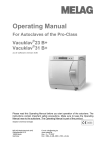
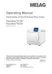
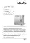
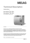
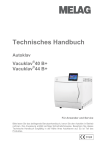
Download Technical Manual - Frank`s Hospital Workshop
Transcript
Technical Manual Autoclave Vacuklav®41-B Vacuklav®43-B For Users and Service personnel Please read the accompanying User Manual before you start operation of the autoclave. The instructions contain important safety precautions. Make sure to keep the Technical Manual together with the User Manual near the autoclave. The instructions are part of the product. Foreword This manual has been created for the autoclaves Vacuklav®41-B and Vacuklav®43-B. They are identical except for their chamber depth and device depth. The device name "autoclave" is used to designate the steam sterilizers Vacuklav®41-B and Vacuklav®43-B. You also receive a User Manual with the autoclave. It contains important safety instructions and information which you need to operate the autoclave. Read the User Manual completely through in proper sequence before beginning operation with the autoclave. This Technical Manual includes declarations of conformity, suitability statements and recommendations, instructions for setting up, installing and initial start-up of the autoclave including installation record, extended technical information on the software and hardware and other technical data. The Technical Manual is meant for interested persons and service personnel. Technical Manual Vacuklav®41-B, Vacuklav®43-B MELAG Medical Technology Berlin Valid for Vacuklav®41-B, Vacuklav®43-B as of software version 2.4x 1st Edition February 2008 Responsible for the contents: Engineering Department MELAG Medical Technology Geneststraße 7-10 10829 Berlin Germany E-Mail: [email protected] www.melag.de © 2008-2009 MELAG Berlin Document: Melag_Vacuklav_41B_43B_TechnicalManual_v3.doc/Revision: 3 – 09/1793 Subject to technical changes Technical Manual Vacuklav®41-B and Vacuklav® 43-B CONTENTS Foreword.......................................................................................................................................................... 2 Device views......................................................................................................................................................... 8 Device views Flex-Display................................................................................................................................... 9 Installation and setting up................................................................................................................................... 10 Removal from the packaging............................................................................................................................ 10 Space requirements......................................................................................................................................... 11 Installation surface............................................................................................................................................ 11 Electrical connection......................................................................................................................................... 11 One-way drain.................................................................................................................................................. 11 Supply with → feed water................................................................................................................................. 12 Installation material........................................................................................................................................... 12 Installation examples........................................................................................................................................ 13 Record of installation and setting up................................................................................................................. 16 Please send to MELAG.................................................................................................................................... 16 Device and installation data.............................................................................................................................. 16 Executed work.................................................................................................................................................. 17 Contrast setting................................................................................................................................................ 19 Counter readings.............................................................................................................................................. 19 Program modifications...................................................................................................................................... 19 Electromagnetic compatibility............................................................................................................................ 20 Electromagnetic environment........................................................................................................................... 20 Recommended protective distances................................................................................................................ 21 Technical tables................................................................................................................................................... 22 Precision and drift behaviour – Sensors ..........................................................................................................22 Precision and drift behaviour – Measuring chain............................................................................................................................................... 22 Precision and drift after 1 year.......................................................................................................................... 22 Precision and drift after 5 years........................................................................................................................ 22 Nominal value tolerances................................................................................................................................. 23 Pressure-Time-Charts...................................................................................................................................... 24 Quality of the → feed water.............................................................................................................................. 26 Frequently asked questions (FAQ) about the software....................................................................................27 Checklist for software update............................................................................................................................. 42 Technical Manual Vacuklav®41-B and Vacuklav®43-B Konformitätserklärung im Sinne der EG Richtlinie über Medizinprodukte 93/42/EWG Declaration of conformity Vacuklav®41-B Vacuklav®43-B In accordance with the EC- guidelines for medical devices 93/42/EWG Manufacturer: Address: Country: Product: Type of device: Classification: MELAG oHG Geneststraße 9 – 10 10829 Berlin Germany Steam sterilizer (autoclave) Vacuklav®41-B/Vacuklav®43-B Class 2a We herewith declare that the above designated product conforms to the following guideline: Appendix I of the EC-guidelines for medical devices 93/42/EWG. Notified body: DEKRA Certification Services GmbH Handwerkstraße 15 70565 Stuttgart No. of registration: 50199-Z2-00 The cited medical device is designated with the CE sign since 25-06-2004. Berlin, 12-03-2008 .............................................. General Management Quality – Made in Germany Evidence Based Sterilization 2 www.melag.de Technical Manual Vacuklav®41-B and Vacuklav®43-B Konformitätserklärung im Sinne der EN 13060 für Dampf-Kle in-Sterilisatoren („Beschein igung“) Declaration of conformity Vacuklav®41-B Vacuklav®43-B Declaration of conformity according to EN 13060 for small steam sterilizers Manufacturer: Address: MELAG oHG Geneststraße 9 - 10 10829 Berlin Germany Steam sterilizer (autoclave) Vacuklav®41-B/Vacuklav®43-B Class 2a Country: Product: Type of device: Classification: We herewith declare that the above designated product conforms to the general requirements set forth in the EN13060 Standard and has successfully passed the Type tests according to EN 13060 for fulfilling requirements on a device with „Class B“ – Sterilization program (B-method) Berlin, 12-03-2008 .............................................. General Management Quality – Made in Germany Evidence Based Sterilization www.melag.de 3 Technical Manual Vacuklav®41-B and Vacuklav®43-B Eignungsbeleg nach den Empfehlungen der KHI am RKI (vom April 2006) Certificate of Suitability Vacuklav®41-B Vacuklav®43-B According to the recommendations of the Commission for Hospital Hygiene and Infection Prevention at the Robert-Koch Institute (of April 2006) Manufacturer: Address: Country: Product: Type of device: Classification: MELAG oHG Geneststraße 9 - 10 10829 Berlin Germany Steam sterilizer (autoclave) Vacuklav®41-B/ Vacuklav®43-B Class 2a We herewith declare that the above designated sterilizer is suited for sterilization of ▪ Solid instruments (wrapped and unwrapped) ▪ Porous goods (wrapped and unwrapped) ▪ Hollow bodies-instruments Type A (wrapped and unwrapped) ▪ Hollow bodies-instruments Type B (wrapped and unwrapped) Instructions on load quantities and loading variants are set forth in the User Manual and must be observed. Be sure to observe the manufacturer's instructions for medical devices intended for sterilization according to DIN ISO 17664. Berlin, 12-03-2008 .............................................. General Management Quality – Made in Germany 4 Technical Manual Vacuklav®41-B and Vacuklav®43-B Evidence Based Sterilization www.melag.de 5 Technical Manual Vacuklav®41-B und Vacuklav®43-B Geeigneter Prüfkörper nach den Empfehlungen der KHI am RKI (vom April 2006) Suitable test body Vacuklav®41-B Vacuklav®43-B According to the recommendations of the Commission for Hospital Hygiene and Infection Prevention at the Robert-Koch Institute (of April 2006) Manufacturer: Address: Country: Product: Type of device: Classification: MELAG oHG Geneststraße 9 - 10 10829 Berlin Germany Steam sterilizer (autoclave) Vacuklav®41-B/Vacuklav®43-B Class 2a We herewith declare that the following test system is suited for testing the above cited sterilizer: Product: Type designation: Helix-Test body according to EN 867-5 MELAcontrol® Berlin, 12-03-2008 .............................................. General Management Quality – Made in Germany Evidence Based Sterilization 6 www.melag.de Technical Manual Vacuklav®41-B and Vacuklav® 43-B Device views Front side (1) Protective cap for slot of the →CF card (2) Control panel (3) Door (pivot opens to the left) (4) Protective cap for manometer to display the pressure of the →double jacket steam-generator (5) Cap for emergency opening of the door (7) Mains switch (concealed, accessible from the side) (8) Ethernet-1-Data connection* (9) Reset button overheating protection* (10) Front foot of the unit (adjustable) *behind covering Back side (11) Tank filler cap (12) Ethernet-2 data connection (13) Ethernet-3 data connection (can be retrofitted) (14) Power cable (15) Safety valve chamber (16) Sterile filter (17) Safety valve double jacket (18) Emergency overflow (19) One-way drain (20) Connection pressure discharge (21) Purified feed water inlet (for MELAdem®, swivelling threaded fitting for hose ∅8x1, alternatively straight) (22) Back foot of the unit (23) Cooler Fig. 1:Front- and rear view 7 Technical Manual Vacuklav®41-B und Vacuklav®43-B Device views Flex-Display Front side (1) Protective cap for slot of the →CF card (2) Control panel (3) Door (pivot opens to the left) (4) Protective cap for manometer to display the pressure of the →double jacket steam-generator (5) Cap for emergency opening of the door (6) (7) Mains switch (concealed, accessible from the side) (8) Ethernet-1-Data connection* (9) Reset button overheating protection* (10) Front foot of the unit (adjustable) *behind covering Back side (11) Tank filler cap (12) Ethernet-2 data connection (13) Ethernet-3 data connection (can be retrofitted) (14) Power cable (15) Safety valve chamber (16) Sterile filter (17) Safety valve double jacket (18) Emergency overflow (19) (20) One-way drain (21) Connection pressure discharge (22) Purified feed water inlet (for MELAdem®, swivelling threaded fitting for hose ∅8x1, alternatively straight) (23) Back foot of the unit (24) Cooler 8 Technical Manual Vacuklav®41-B and Vacuklav® 43-B Installation and setting up Warning Please read the User Manual of the autoclave and the water treatment unit before setting up the autoclave. If the autoclave has already been put into operation, please observe the following before setting up again in case of any eventual transport: Warning ■ ■ To transport the autoclave, for instance if the practice moves to a new location, wait until the pressure indicator on the manometer display shows null bar after the autoclave is switched off. Be sure to check the pressure indicator on the manometer before moving the autoclave To transport the unit over longer distances, an →authorised person must prepare the autoclave beforehand according to instructions and completely empty the →double jacket steam generator. In order to do so, you can use the Draining program in the SPECIAL menu. Non-compliance can lead to severe burns and damages to the autoclave as well as malfunctions. The autoclave sterilizes on the basis of the →fractionated vacuum. A membraneous pump is used to create the especially deep vacuum. Thus the autoclave can be immediately put into operation without additional installation work, apart from providing the necessary power supply. For the optional connection of the one-way drain and an external water treatment unit please follow the water main and general information for the proper installation which must be observed when setting up the device. Removal from the packaging Unpack autoclave Remove carrying strap After switching on Lift the autoclave out of the carton with the carrying strap. To remove the carrying strap, unscrew the four screws on each side of the housing. Retighten these screws firmly without the washers. Keep the carrying strap and the washers. After switching on the autoclave and before initial start-up, open the door and remove the trays and the accessories from the chamber. ▪ Notice! 9 To do this you must go into door mode: Press the Door button on the Welcome start screen; afterwards the door can be opened. After 5 seconds of inactivity, the display automatically switches back to the main menu. The autoclave then begins to suck in the feed water needed for the sterilization, which triggers an error message! Installation and setting up Space requirements The space requirements for the autoclave corresponds to its dimensions plus at least 5 cm on the side and 10 cm at the back side. The autoclave should be freely accessible from above, for easy filling of the storage tank and to ensure proper ventilation. The autoclave works with a cooler located at the rear of the device. The function and service life can be impaired if the heat dissipation over the cooler is restricted. Therefore we do not recommend incorporating the autoclave; this is only possible if sufficient air circulation is ensured. Dimensions in parentheses: Vacuklav®43-B Fig. 2: Dimensions Vacuklav®41-B/43-B For →Feed water supply In case of external feed water supply there is additionally required space for the water treatment unit MELAdem40 or MELAdem47. Installation surface Flat and level Load capacity Place the autoclave on a flat and level surface. The Vacuklav®41-B weighs without load and without feed water 59 kg. The Vacuklav®43-B weighs without load and without feed water 66 kg. Electrical connection Power socket Power cable Log printer MELAprint®42 230 V, 50 Hz, connected load 3400 VA, separate fuse protection 16, protection from leakage current 30 mA The power cable is 1.35 m long. If you want to connect a log printer to the autoclave, you need another socket for its power supply. One-way drain Wall drain or siphon drain Waste water hose One-way overflow hose on the siphon A wall drain, nominal DN40 or a siphon drain (sink drain) is required for the one-way drain. A 1 m wastewater hose (MELAG Art. No. 39180) can be ordered from MELAG to directly connect the autoclave to the waste water, i.e. the pressure discharge goes directly into the siphon of the domestic water supply. If you close the one-way overflow hose of the autoclave at the siphon of the domestic water supply, you need a 2 m wastewater hose (Art. No. 36585) which you can also order from MELAG. The drain must be located at least 30 cm beneath the autoclave and be installed dip-free with continuous descent. 10 Installation and setting up Supply with → feed water Feed water one-way system Quality of feed water Provide feed water supply from internal storage tank Notice! Since the contamination of feed water in autoclaves using a water circulation system regularly leads to early damages to the autoclaves and instruments, the autoclave works in the gentle yet effective one-way water system. This means that it uses fresh purified feed water for every sterilization run. The autoclave gets the feed water either from a water storage container which the practice team has refilled e.g. with distilled water from the MELAdest®65. Or it gets the feed water fully automatically from the water treatment unit MELAdem®40 or MELAdem47. The quality of the →distilled or demineralized feed water for the steam generation must be at least VDE 0510. Before the initial start-up of the autoclave, the right chamber of the internal storage tank of the autoclave must be filled with feed water up to the maximum marking. At the initial start-up of the autoclave, the unit needs to be filled once with 2.5 L to fill the double jacket. For this reason we recommend you to refill the right chamber of the internal storage tank afterwards immediately. Installation material Additional material, that can be ordered Water connection-Set MELAdem®40 Water connection-Set MELAdem®47 Water connection-Set consisting of (contained in Art. No. 09033 and 09034: Feed water-inlet fixtures for hose ∅6x1 (replaces pipe fitting for hose ∅8x1) Hollow screw for feed water inlet fixtures 2x Cu seal 1/8“ for Art. No. 53461 2x Cu seal 1/4" for Art. No. 53471 (replace by twisting Art. No. 53471) Pressure discharge fitting (1/4"-fast screw connection for hose (∅8x1 (screw on at the device) One-way drain hose PTFE-pipe ∅8/6 –cut to size One-way drain hose (overflow hose, 2m) Surface-mounted siphon with double hose nozzle Double hose nozzle with anti-flooding flap for connection to existing sink siphon Water tap 3/4“ (with safeguard combination) additional tap with return flow inhibitor and pipe aerator (to attach to an available angle valve) Leak monitor (water stop) with shut-off valve and probe Safety combination, consisting of return flow inhibitor and pipe aerator according to EN 1717 MELAG Art. No. 09033 09034 25655 21140 53430 42360 36060 53471 39180 36585 37410 37400 37310 58130 01056 49600 Table 1: Installation material 11 Installation and setting up Installation examples Example 1 – Standard scope of delivery Direct of →feed water from the internal storage tank Wastewater is collected in the wastewater chamber of the storage tank No water connection necessary The autoclave is supplied with feed water directly over a hose from the internal storage tank. Thus no additional water connection is required aside from the power supply line. An integrated float-actuated level switch in the device notifies a lack of feed water. A program can be started only after water is refilled. The used feed water (wastewater) is collected in the wastewater chamber of the internal storage tank and later drained off manually. A float-actuated level switch in the wastewater chamber also notifies that the wastewater chamber is full. Fig. 3: Direct feed water supply from the internal storage tank (1) Tank filler cap (2) Sterile filter (3) Safety valve chamber (4) Safety valve double jacket (5) Emergency overflow (6) One-way drain (7) Connection pressure discharge (8) Feed water inlet fitting (9) Power cable (10) Cooler (11) Ethernet-3-Data connection (can be retrofitted) (12) Ethernet-2-Data connection Example 2 – MELAdem®40 12 Supply of →feed water from the Ion exchanger MELAdem®40 Pressure discharge is directly connected with siphon Installation and setting up Connection of the ion exchanger MELAdem40 with MELAjet®. The simplest installation is to connect the MELAdem40 directly to the purified feed water inlet of the autoclave and thus generate demineralized water from normal tap water. The spray pistol MELAjet® is for the final rinsing of the instruments with demineralized water before sterilization. Fig. 4: Feed water-supply from the Ion exchanger MELAdem40 (1) Safety combination, consisting of return flow inhibitor and pipe aerator according to EN 1717 (2) MELAjet® (MELAG Art. No. 30300 – optional) (3) MELAdem®40 (4) One-way drain (5) Feed water inlet fitting (swivelling threaded fitting for hose ∅6x1, alternatively straight) (6) Inlet hose feed water (7) Feed water filter MELAdem® (8) Wall drain (available on-site) (9) (10) Double hose nozzle with anti-flooding flap (MELAG Art. No. 37400 – in the surface-mounted-siphon (contained in Art. No. 37410) Pressure discharge hose (MELAG Art. No. 39180) (11) Water tap (available on-site) (12) (13) Leak monitor (water stop) with shut-off valve and probe (MELAG Art. No. 01056 – optional), recommended with fixed water connection Power cable (14) Cooler (15) Ethernet-3 Data connection (can be retrofitted) (16) Ethernet-2 Data connection Before you upgrade from the standard version to one with a water treatment unit, empty both chambers of the internal storage tank! The feed water inlet fixture (5) on the autoclave must be exchanged with the hollow screw (MELAG Art. No. 53430) with feed water inlet fixture for hose ∅6x1 (MELAG Art. No. 21140) because of the other hose diameter. Likewise exchange the two Cu seals (MELAG Art. No. 42360) – in the water connection set). The used feed water (wastewater) is conducted under pressure directly over the one-way drain hose (MELAG Art. No. 39180) into the siphon of the domestic water supply. An automatic one-way-overflow is also possible and is described in example 3. 13 Installation and setting up Example 3 – MELAdem®47 Supply of →feed water from the reverse osmosis unit MELAdem 47 Drain via one-way drain and doublechamber wastewater trap Connection of the reverse osmosis unit MELAdem®47, which can be directly attached to the purified feed water inlet of the autoclave. Other water treatment units with corresponding water quality can also be connected after consultation with MELAG. Fig. 5: Feed water-supply from the reverse osmosis unit MELAdem47 (1) Tank filler cap (2) (3) Safeguard combination, consisting of a return flow inhibitor and pipe aerator according DIN EN 1717 – optional One-way drain (4) Feed water tap (5) Feed water inlet fitting (swivelling threaded fitting for hose ∅6x1, alternatively straight) (6) Feed water filter MELAdem® (7) Double-chamber waste water trap (MELAG Art. No. 26635) (8) Wall drain (NW40 – available on-site) (9) Double hose nozzle with anti-flooding flap (MELAG Art. No. 37400 – contained in the surface-mounted siphon with Art. No. 37410 (10) Concentrate drain MELAdem®47 (11) Inlet hose feed water (12) One-way overflow hose (MELAG Art. No. 36585) (13) MELAdem®47 (14) Water tap (available on-site) (15) Power cable (16) (17) Leak monitor (water stop) with shut-off valve and probe (MELAG Art. No. 01056 – optional), recommended with fixed water connection Ethernet-3 Data connection (can be retrofitted) (18) Ethernet-2- Data connection Installation as in example 2 – MELAdem®40. The wastewater drainage is automated here. The one-way overflow hose (12) is connected to the one-way drain of the autoclave and connected over the double hose nozzle (9) with the double-chamber wastewater trap (7). In the case of direct connection of the water treatment unit to the domestic water supply, we recommend the additional Installation of the leak monitor (water stop valve) with shut-off valve and probe (16). 14 Fax +49(0)30 75791199 Telephone +49(0)30 7579110 Record of installation and setting up Please send to MELAG. Dear Madam/Sir, within the scope of Quality Assurance we are obligated, in cooperation with you, the responsible specialist MELAG dealer, to install this MELAG autoclave at the operator's in accordance with good engineering practice and provide instructions in its use. Please copy, fill out and sign this form and send it to us after the autoclave has been successfully installed. MELAG Medical Technology Geneststraße 7 - 10 10829 Berlin The returned form is prerequisite for the MELAG factory warranty. Device and installation data We, hereinafter referred to as specialist MELAG dealer, have today installed, instructed the personnel and performed the initial start-up of the autoclave Vacuklav ® 41-B/43-B as described below: Specialist dealer (name, address, stamp) Operator (name, address/ stamp) ………………………………………………………………. ………………………………………………………………. E-mail-address for software update E-mail-address for software update ………………………………………………………………. ………………………………………………………………. Serial No. Vacuklav® 41-B/43-B Remarks ………………………………………………………………. ……………………………………………………………… Please place checkmark where applicable O First installation O Date ……………………………………………………………… Subsequent installation The following persons were present during the instructions for use: Name, first name (please print in block letters) From the practice/ clinic: Signature ………………………………………………………...... ……………………………………. ………………………………………………………….. ……………………………………. ………………………………………………………….. ……………………………………. ………………………………………………………….. ……………………………………. Name, first name (please print in block letters) 15 Signature Instructing technician ………………………………………………………….. ……………………………………. From the company: ………………………………………………………….. ……………………………………. Record of installation and setting up Executed work Please confirm the respective points with a checkmark after completion of the described task Secure feed water supply (depending on installation variant O Right feed water chamber of the internal storage tank filled up with feed water O O O Water treatment unit MELAdem®40 or MELAdem®47 set up according to installation instructions In case of installing a water treatment unit : Autoclave was set in the user menu on „water supply – extern“ It was pointed out that demineralized water with a minimum quality according to VDE 0510 must be used as feed water, and the items to be sterilized must be clean and free of cleanser and disinfectant residues Install wastewater connection (depending on installation variant) O Wastewater is collected in the internal storage tank (no wastewater connection) O One-way drain connected to the existing siphon of the domestic water supply or the double-chamber wastewater trap from MELAG Align the autoclave For fault-free operation, the autoclave must be set up horizontally with the help of a water level located close to the sterilization-chamber flange. Then depending on the type of autoclave, the front feet of the unit must be unscrewed by about three or five rotations in order to give the autoclave a slight backwards tilt. O Vacuklav®41-B: front feet of the unit screwed out 3 rotations O Vacuklav®43-B: front feet of the unit screwed out 5 rotations Conduct and record vacuum test with empty chamber and Universal-Program with 1.5 kg load (instruments) O Vacuum test performed with empty cold chamber. Leakage: ……………..mbar/min O O Universal-Program successfully executed with about 1.5 kg load (instruments) A printout of the program cycle was created with the log printer MELAprint®42 and pasted into lower fields provided for this purpose O No printer available – leakage rate and successful run of the Universal-Program were recorded in the fields provided for this purpose n Check the time setting, if necessary reset the time according to instructions in the User Manual O Time is correct or correctly reset Reset service meter according to separate instructions O Service meter is reset O Service meter is not reset Instructing the operating personnel and handing over the technical documentation O Instruction on documenting with CF card to archive and print out the data has been concluded O O O O O Operating personnel were instructed O User Manual was handed over Technical Manual was handed over Chamber certificate was handed over MDD Certificate of Conformity was handed over Warranty Certificate was handed over The device was properly installed by the above named technician O without fault O with fault: Logs ……………………………………………………………………………………….. ........ Vacuum test Universal program Please paste and fold up logs here; if no printer is available, then enter leakage rate and successful completion of the Universal program. 16 17 Technical Manual Vacuklav®41-B and Vacuklav® 43-B Contrast setting You can set the contrast of the →Display in the SETUP menu. To do so, select the option Display Contrast. Press Edit, so that reverse display appears. Increase or reduce the contrast of the display by holding down the navigation keys respectively. Exit the SETUP menu by pressing MENU exit and SAVE, to permanently save the contrast setting. Counter readings You can retrieve counter readings and other current technical data of the autoclave in the INFO Menu Counter Readings. To get to the menu, simultaneously press the keys 2 + 3. Program modifications The autoclave program cycles correspond to the practice-relevant requirements of fractionation, heating up, sterilization, pressure discharge, drying and ventilation with their parameters of pressure, temperature and time. Additional drying The standard function of additional drying provides an option for influencing the program cycle. Further changes to the program cycles are possible in individual cases and within the scope of the guaranteed sterilization efficiency, but can only be executed by authorised persons. Please consult your specialist dealer or contact MELAG. 18 Technical Manual Vacuklav®41-B and Vacuklav® 43-B Electromagnetic compatibility Electromagnetic environment Warning The autoclave is designed for operation in an environment as described below. The customer or user must ensure that the autoclave is operated in such an environment as here described The abbreviation HF is used for high frequency in the following tables. Emitted interference measurements Compliance Electromagnetic environment guideline HF emissions as per CISPR 11 Group 1 The autoclave uses HF energy exclusively for its internal function. Consequently, its HF emission is very slight, and it is unlikely that adjacent electronic instruments might be disturbed. HF emissions as per CISPR 11 Class B Emissions of harmonics as per IEC 61000-3-2 Class A The autoclave is suited for use in all facilities including those containing living areas and those which are directly connected to a public supply system which likewise serves residential buildings. Emissions of voltage fluctuations / flickers as per IEC 61000-3-3 Complies Table 2: Electromagnetic compatibility - Emitted interference measurements Interference im- IEC 60601 munity tests test level Compliance level Electromagnetic environment guideline Electrostatic discharge (ESD) as per IEC 61000-4-2 ±6kV contact discharge ±6kV contact discharge ±8kV air discharge ±8kV air discharge Floors should be made of wood or concrete or laid with ceramic tiles. If the flooring is furnished with synthetic material, the relative humidity must be at least 30%. Rapid transient electrical disturbances/ bursts as per IEC 61000-4-4 ±2kV for mains cables ±2kV for mains cables ±1kV for input and output cables ±1kV for input and output cables Surges as per IEC 61000-4-5 ±1kV push-pull voltage ±1kV push-pull voltage ±2kV common-mode voltage ±2kV common-mode voltage Voltage drops, short-term interruptions and fluctuations of the supply voltage as per IEC 61000-4-11 <5% UT* (5% sag of the UT) for ½ period <5% UT* (95% sag of the UT) for ½ period The quality of the supply voltage should correspond to a typical business or hospital environment. The quality of the supply voltage should correspond to a typical business or hospital environment. The quality of the supply voltage should correspond to a typical business or hospital environment. <40% UT* (60% sag of the <40% UT* (60% sag of the If the autoclave user demands continual functionUT) for 5 periods UT) for 5 periods ing of the device even when there are interruptions <70% UT* (30% sag of the <70% UT* (30% sag of the in the energy supply, we recommend supplying the autoclave from an interruption-free power supply UT) for 25 periods UT) for 25 periods or a battery. <5% UT* (95% sag of the <5% UT* (95% sag of the UT) for 5 s UT) for 5 s Magnetic fields 3 A/m with the supply frequency (50Hz) as per IEC 61000-4-8 3 A/m Magnetic fields with the mains frequency should correspond to the typical values found in the business and hospital environment. * UT is the ac mains supply before the application of the test level Table 3: Electromagnetic compatibility - Interference immunity tests 1 19 Technical Manual Vacuklav®41-B and Vacuklav® 44-B Interference im- IEC 60601 munity tests test level conducted HF dis- 3 Veff turbances as per 150 kHz to 80 MHz IEC 61000-4-6 radiated HF disturbances as per IEC 61000-4-3 3 V/m Compliance level Electromagnetic environment guideline*1 Portable and mobile radio equipment should not be placed closer to the autoclave (including hoses and pipes) than the recommended protective distance calculated according to the formula for the transmitting frequency. (see table below: Recommended protective distances) 3 Veff The field intensity of stationary radio transmitters should be less than the compliance level for all frequencies according to an on-site*2 investigation*3. 3 V/m 80 MHz to 2.5 GHz Disturbances are possible in the environment of devices bearing this symbol. *1 This guideline might not be applicable in all cases. The dispersion of electromagnetic magnitudes is influenced by the absorption and reflection of buildings, objects and people. 2 The field intensity of stationary transmitters, such as e.g. base stations of radio telephones and mobile land radio devices, amateur radio stations, AM and FM radio broadcasting and TV transmitters are not able to be exactly theoretically determined beforehand. You should consider conducting a study of the location to determine the electromagnetic environment with respect to the stationary transmitters. If the measured field intensity at the location where the autoclave is to be used exceeds the above compliance level, then observe the autoclave carefully to verify its proper functioning. If unusual performance characteristics are observed, additional measures might be required, such as for instance modifying the alignment or finding another location for the autoclave. *3 Within the frequency range of 150 kHz to 80 MHz, the field intensity should be less than 3 V/m. Table 4: Electromagnetic compatibility - Interference immunity tests 2 Recommended protective distances Between portable and mobile HF telecommunication devices and the autoclave The autoclave is designed for operation in an electromagnetic environment in which the HF disturbances are monitored. The customer or the user of the autoclave can thus help to avoid electromagnetic disturbances by complying with the minimum distance required between portable and mobile HF telecommunication devices (transmitters) and the autoclave, depending on the power output of the communication device, as stated below. For transmitters whose maximum nominal power is not specified in the following table, the recommended protective distance d in meters (m) can be determined by using the equation in the respective column, whereby P is the maximum nominal power of the transmitter in watt (W) according to the specifications of the transmitter manufacturer. Nominal power of the transmitter [W] Protective distance depending on the transmitting frequency [m] 150 kHz to 80 MHz* 80 MHz to 800 MHz* 800 MHz to 2.5 GHz* d =1.2 P d =1.2 P d = 2.3 P d… recommended protective distance in meters P… maximum nominal power of the transmitter in watt according to information of the transmitter manufacturer * 0.01 0.12 0.12 0.23 0.1 0.38 0.38 0.73 1 1.2 1.2 2.3 10 3.8 3.8 7.3 100 12 12 23 For 80 MHz and 800 MHz the higher frequency range applies Table 5: Electromagnetic compatibility -Protective distance depending on the transmitting frequency [m] 20 Technical Manual Vacuklav®41-B and Vacuklav® 43-B Technical tables Precision and drift behaviour – Sensors Sensor type PT 1000 Class A according to DIN EN 60751 Precision at 135 °C ±0.42 K Drift per year ±0.05 K Drift in 5 years ±0.25 K Table 6: Precision and drift behaviour of the temperature sensors n Sensor type piezoresistant absolute pressure sensor 0 to 4000 mbar Precision ±0.3 % corresp. to ±12 mbar corresp. to ca. ±0.13 K steam Drift per year ±0.2 % corresp. to ±8 mbar corresp. to ca. ±0.09 K steam Drift in 5 years ±1.0 % corresp. to ±40 mbar corresp. to ca. ±0.44 K steam Table 7: Precision and drift behaviour of the pressure sensor Precision and drift behaviour – Measuring chain Precision at 135 °C ±0.2 K Drift per year ±0.005 K Drift in 5 years ±0.025 K Table 8: Precision and drift behaviour of the measuring chain for the temp. measurement on the electronics (w/o sensor) Precision ±0.2 % corresp. to ±8.0 mbar corresp. to ca. ±0.09 K steam Drift per year ±0.004 % corresp. to ±0.16 mbar corresp. to ca. ±0.017 K steam Drift in 5 years ±0.02 % corresp. to ±0.8 mbar corresp. to ca. ±0.09 K steam Table 9: Precision and drift behaviour of the measuring chain for the pressure measurement on the electronics (w/o sensor) Precision and drift after 1 year Precision at 135 °C at pure addition of indiv. errors ca. ±0.70 K Precision at 135 °C per Gaussian law of propagation ca. ±0.47 K Table 10: Precision including drift of the entire measuring chain of the temperature measurement after 1 year Precision at pure addition of indiv. errors ±0.70 % corresp. to ±28.0 mbar corresp. to ca. ±0.30 K steam temp. Precision per Gaussian law of propagation ±0.41 % corresp. to ±16.5 mbar corresp. to ca. ±0.18 K steam temp. Table 11: Precision including drift of the entire measuring chain of the pressure measurement after 1 year Precision and drift after 5 years Precision at 135 °C at pure addition of indiv. errors ca. ±0.70 K Precision at 135 °C per Gaussian law of propagation ca. ±0.47 K Table 12: Precision including drift of the entire measuring chain of the temperature measurement after 5 years Precision at pure addition of indiv. errors ±0.70 % corresp. to ±28.0 mbar corresp. to ca. ±0.30 K steam temp. Precision per Gaussian law of propagation ±0.41 % corresp. to ±16.5 mbar corresp. to ca. ±0.18 K steam temp. Table 13: Precision including drift of the entire measuring chain of the pressure measurement after 5 years 21 Technical Manual Vacuklav®41-B and Vacuklav® 43-B Nominal value tolerances Tolrenaces for nominal values to be achieved by Premium autoclaves ◄ ◄ ◄ ◄ ◄ ◄ ◄ ◄ ----◄ ◄ ◄ ◄ ◄ ◄ ◄ ◄ ------◄ ◄ ◄ ◄ ◄ ◄ ◄ ◄ ◄ ◄ ◄ ◄ ◄ ----◄ ◄ ◄ ◄ ◄ ◄ ◄ ◄ ------◄ ◄ ◄ ◄ ◄ Prion pr. P Tol. Gentle pr. P Tol. ◄ ◄ ◄ ◄ ◄ ◄ ◄ ◄ ◄ ◄ ◄ ◄ ◄ ◄ ◄ ◄ ◄ ◄ ◄ ◄ ◄ ◄ ◄ ◄ ◄ ◄ ◄ ◄ ◄ ◄ ◄ ◄ ◄ ◄ ◄ ◄ ◄ ◄ ◄ ◄ ◄ ◄ ◄ ◄ ◄ ◄ 1500 1850 1950 2080 2150 1300 ◄ ◄ ◄ ◄ ◄ ◄ ◄ ◄ ◄ ◄ ◄ ◄ ◄ ◄ ◄ ◄ ◄ ◄ ◄ ◄ ◄ ◄ ◄ ◄ ◄ ◄ Table 14: Tolerances for nominal values in the program cycle 22 ◄ ◄ ◄ ◄ ◄ ◄ ◄ ◄ ◄ ◄ ◄ ◄ ◄ ◄ ◄ ◄ ◄ ◄ ◄ ◄ ◄ ◄ ◄ ◄ ◄ ◄ Quick S ◄ same meaning as in Universal pr. P Tol. Alle values in mbar steam entry ◄ ◄ pressure release ◄ ◄ steam entry --- --pressure release --- --steam entry ◄ ◄ pressure release ◄ ◄ steam entry --- --pressure release --- --steam entry --- --pressure release --- --evacuate ◄ ◄ steam entry ◄ ◄ pressure release ◄ ◄ evacuate 380 ◄ steam entry ◄ ◄ pressure release --- --evacuate --- --steam entry --- --pressure release --- --evacuate --- --steam entry --- --keep. steam entry ◄ ◄ keep control ◄ ◄ sterilization start ◄ ◄ sterilization ◄ ◄ pressure release ◄ ◄ Conditioning Quick B P Tol. Fractionation Universal program Step Press. P Tolerance SK11 1600 +100/ - 20 SK12 1300 + 20/ - 50 SK11 1600 +100/ - 20 SK12 1300 + 20/ - 50 SK21 1600 +100/ - 20 SK22 1300 + 20/ - 50 SK21 1600 +100/ - 20 SK22 1300 + 20/ - 50 SK21 1600 +100/ - 20 SK22 1300 + 20/ - 50 SF12 500 + 30/ - 30 SF13 1600 +100/ - 20 SF21 1300 + 20/ - 50 SF22 180 + 30/ - 30 SF23 1800 +100/ - 20 SF31 1300 + 20/ - 50 SF32 200 + 30/ - 30 SF33 1900 +100/ - 20 SF41 1300 + 20/ - 50 SF42 400 + 30/ - 30 SF43 1700 +100/ - 20 SH01 2750 + 60/ - 60 SH02 2850 + 60/ - 60 SS01 3080 + 60/ - 60 SS02 3170 + 60/ - 60 SA00 1300 + 20/ - 50 Technical tables Pressure-Time-Charts Fig. 6: Pressure-Time chart for Universal-Program, 134 °C and 2.1 bar Fig. 7: Pressure-Time chart for Quick-Program B, 134 °C and 2.1 bar 23 Technical Manual Vacuklav®41-B and Vacuklav® 43-B Fig. 8: Pressure-Time chart for Quick-Program S, 134 °C and 2. bar Fig. 9: Pressure-Time chart for Gentle-Program, 121 °C and 1.1 bar 24 Technical tables Fig. 10: Pressure-Time chart for Prion-Program, 134 °C and 2.1 bar Quality of the → feed water Residue on evaporation ≤ 10 mg/L Silcon, SiO2 ≤ 1 mg/L Iron ≤ 0.2 mg/L Cadmium ≤ 0.005 mg/L Lead ≤ 0.05 mg/L Heavy metals except for those named ≤ above 0.1 mg/L Chlorides ≤ 2 mg/L Phosphate ≤ 0.5 mg/L ph value 5–7 Colour colourless, clear, without sediments Hardness ≤ 0.02 mmol/L Table 15: Minimum requirements to the feed water following the EN 13060, Appendix C 25 Technical Manual Vacuklav®41-B and Vacuklav® 43-B Frequently asked questions (FAQ) about the software 1 Version 2.4 Which improvements do the software versions V2.0, V2.2 and V2.3, V2.4 contain? A program start time can be pre-set to any time using the pre-selection Start time function. (key #4) ▪ Additional drying is selection using the #1h key The energy saving mode was supplemented in the SETUP menu ▪ The program Draining was supplemented in the SPECIAL Menu Version V2.3: ▪ Logs can now be read out by a suitable program (e.g. MELAview V2.0) via a TCP Port ▪ The FTP server password consists of the word MELAG+ a five digit sequence, which can be changed in the SETUP Menu under LAN TCP/IP FTP FTP-Server-Password-Attachment ▪ During a program run, it s possible to record graphic logs in real time (via a CF card or computer) and displayed in MELAview V2.0 as a curve diagram. We recommend using MELAflash CF cards with a minimum of 1GB memory capacity. ▪ By calling up the MELAnet website it is possible to follow the program status on the computer during a running program via a browser window. ▪ Changes of the Quick-Program B unwrapped into Quick-Program B for single wrapped instruments; loading with simple packaged instruments up to maximum 1.5 kg or with unpacked instruments up to maximum 5 kg is possible. With the new key DETAILS, the log recording state, conductivity, temperatures, pressures and software version can now be displayed in alarm and fault messages Selection state of the journal list in the DOKU menu is now retained after OUTPUT ▪ ▪ ▪ Further improved recognition of CF cards of other manufacturers Version V2.2: ▪ ▪ ▪ Insignificant change of the keyboard layout for messages Employment of CF cards of diverse manufacturers possible Batch documentation in the SETUP Menu now means Automatic logging V2.0: Network capability ▪ Computer and/or MELAprint® 42 can be connected to the autoclave directly or over the computer network. Simple network integration of the autoclaves by means of IP address menu. ▪ V2.0: Intelligent batch documentation ▪ ▪ ▪ ▪ ▪ 26 Every combination of the output medium CF card, computer and MELAprint® can be set. For every selected medium, autoclave "stores" log records that have not been outputted and outputs these automatically at the next opportunity. Autoclave automatically creates its own directories on the CF card or computer (device directory, therein month directories, directory is doubled) Three formats can be selected for the report output: 0: without program steps, 1: with program steps without explanation, 2: with program steps and their explanation Electronic "stamp" in the journal as authenticity proof (assurance Frequently asked questions (FAQ) about the software ▪ ▪ V2.0: DOCU menu ▪ ▪ ▪ ▪ ▪ V2.0: Door ▪ ▪ V2.0: Miscellaneous ▪ ▪ ▪ ▪ ▪ ▪ ▪ 2 against manipulation). Formatting CF Cards at the autoclave is possible Aside from the automatic log, any number of media can be selected for a "manual" log output Still more criteria for the selection of log output Individual output of logs with the journal list, including sort function. Specification of a consecutive identification number of the device events, such as E065, for messages, cautionary notes or fault messages. Output of the error texts in the log. Door mode ("door" button after switching on) permits the door opening without starting up the autoclave. Door motor functions and messages integrated for Vacuquick File names of the update modules now permit both recognition of version as well as type and language. Blocking/skipping of programs with a parameter change is possible. Access to DEMO mode and service counter is simplified. DEMO mode is recognizable during program sequence and in the logs (inverse texts). Message "only for unwrapped instruments" also appears in the DEMO mode No feed water cautionary notes or fault messages any longer in the DEMO mode Total batch number from service after an exchange of circuit boards can be set. Fault messages defined and display texts optimized What does the lighting of the LED next to the card slot signify? short lighting up (1 s) ▪ ▪ During boot loader phase (device ON) After CF card was inserted in the card slot Blinking (every 0.5 s) ▪ No firmware present; occurs e.g. after power loss or during an update process, if for instance the update CF card is too rapidly removed; in this case a CF card with firmware must be plugged in during the boot loader phase (see Question 15, Page 37) so that the device can run again Long lighting (up to 1 min) ▪ After apparatus is switched on with inserted update CF card, which is then automatically recognized. The light can be interrupted between the downloading of the files. Therefore you must wait until the start screen (droplet picture) appears. Attention ▪ Flicker (lighting up of the LED) at irregular intervals 3 Storing of logs on the MELAflash CF Card; the process takes longer as of V2.0 due to the automatic verification and creation of the directories How do I recognize the batch number of the completed cycles? You have the following options for examining the batch number of a completed cycle: On the end image of the display With the DOKU key After a completed cycle, also for programs terminated by the operator or system, an end screen display appears. As of V2.0, the entire batch number of the concluded program is displayed here in the user interface. In the end image, you can display the log header by pressing the button 27 Technical Manual Vacuklav®41-B and Vacuklav® 43-B DOCU, where you can ascertain for instance the day and the entire batch number. In the log header In every log (paper printout or file), the total batch number is cited in the log header. 4 How can I format a CF card at the autoclave itself? Attention All saved data on the CF card is deleted during formatting! Therefore you should check the CF card contents and save possibly existing backup records or other data on the PC or on some other storage medium. Procedure for formatting 1. Stick the CF card correctly into the card slot (noticeable raised rib at the edge points to the display), on no account apply force 2. Select main menu SPECIAL Menu DOCU Menu Media se3. 5 As of V2.0, it is possible and safer to format the CF card at the autoclave (see question 5). lection in screen Key CONTINUE 15 Format CF card Format CF card in screen? Button YES If the message "formatting completed" appears, you can remove the CF card How is a CF card formatted at the PC so that it is recognized by the autoclave? The following is therefore only conditionally interesting: The CF card must be formatted with the file system FAT16. Only on cards formatted in such a manner can the autoclave store or read data. Cards delivered by MELAG are already correctly formatted. The formatting on the PC can be done without problems only with Windows XP: 1. Plug the CF card into the MELAflash card reader which is installed and connected at the PC 2. Click START 3. Click Execute… 4. Enter the format command as specified below in the input field of the Execute window. X stands for the letter of the hard drive of the card reader, A determines the cluster size on the CF card, which varies depending on the memory capacity of the CF card (see Table 16, page 14). 5. Confirm the entry of the format command and if desired enter a name (max. 8 characters) for the CF card. In the log header In every log (paper printout or file), the total batch number is cited in the log header. capacity of format instructhe CF card tion to be entered 2 GB format X: /A:32K 1 GB format X: /A:16K By adjusting parameter A you for instance prevent Windows XP from otherwise automatically formatting with FAT16 or FAT32 depending on the card size. We recommend using MELAflash CF cards with a minimum of 1GB memory capacity in accordance with the latest technical standards. Table 16: Format Instruction to be entered depending on the memory capacity of the CF card 28 Frequently asked questions (FAQ) about the software 6 Where do I find the outputted logs? After a log output a directory is automatically created with the encoded serial number of the respective autoclave. the name of the directory consists of five characters, which are identical to the first five characters of every log, e.g. 43D0J. Under this directory there are subdirectories with the months of the log creation, e.g. 12_2008 for December 2008. The subdirectories contain all the logs created by the autoclave in the respective month. The device directory in the main directory is created on the CF card. After log output in the device directory on all memory media When using the MELAG FTP server Direct transfer of the log on a computer via the network and using the MELAG FTP server allows you to determine directly in the FTP server where on your computer the device directory with log files is to be saved. Do not rename directories For every type of log output (immediate printout after run cycle or transfer of multiple log records at once), the autoclave also verifies the storage medium and automatically creates a directory of the device and the month if none exists. Do not rename the directories, since then the logs would be stored both in the renamed directory as well as in the device directory automatically recreated by the autoclave. Directory "doubled" If multiple log records are outputted on one and the same storage medium, then in the device directory a directory "double" is created in which these log records are stored once. 7 Position 1 2 Example 8 3 What do the numerals and letters in the directories and log file name mean 3 4 5 6 7 8 D 0 J 0 B M . X X X P R O Serial number Meaning Year of manuf. Type Explanation 6…2006 7…2007 8…2008 9…2009 . . . A…2013 B…2014 0…40-B 1…41-B 3…43-B 4…44-B . . . 8…13-B 9…14-B Manuf. No. → Batch Manuf. No. and total batch numbers are converted according to the same principle. A small Excel application facilitates the conversion Log file extension PRO… GPD STR… STB… LOG… STA… LEG… DEM… DES… successful program Graphic log malfunction malfunction in standby system log status log abbreviation legend demo log demo malfunction Table 17: Explanation of the numerals and letters in the directory and log names based on an example Log files must be allocated to a text editor in order to open them easily A PC is initially not aware of the extensions of the log files. If you permanently allocate a log file with the corresponding typical file extension to the text editor program, then you can always open this file type with a doubleclick from then on (see Question 8). Do not rename log file names A complete encryption of both the serial number as well as the total batch number is carried out directly in the eight-place log file name. A manual renaming of a file is therefore discernible, but not recommended. A file name is not allocated twice. The log file name ensures a good sortability of records. Date and time of the log files Date and time of the log files in the Windows Explorer are identical with the date and time of the program start, provided that these were saved on the respective medium by immediate printout. For later collected output on a medium or for sending by e-mail, this information is lost. Serial No. and total batch number are found in the log It is not necessary to know the encryption within the name of the log file, since by double-clicking on the file the contents and hence also the serial 29 Technical Manual Vacuklav®41-B and Vacuklav® 43-B file number and total batch number can be seen. The prerequisite is the above mentioned allocation of the log file to a text editor (see Question 8). Total batch number must be entered when the circuit board is exchanged In the rare event that a circuit board must be exchanged, the total batch number must be entered. This is possible for authorized experts in the SERVICE menu. 8 The program MELAview V2.0 for displaying, editing and printing log files How can I open and print a log file? (MELAview) MELAview V2.0 is a program developed by MELAG for displaying and sorting sterilization logs. Furthermore, you have the option of logging graphic logs during a program run. Text and graphic logs can be printed from MELAview V 2.0 or exported in various data formats. For test purposes you can display DUMMY logs without a license code. The complete autoclave protocol function of MELAview V2.0 can only be used with a license which has to be purchased. An installations assistant leads you through the installation of the program. Regular transfer of log data from CF card to the PC The program MELAview V2.0 does not have any administration functions. This means for example, that logs are not automatically synchronized with the log storage folder on your computer by a CF card. The MELAview program has no administrative functions. This means that the log files are not automatically synchronized from a CF card with the folder for log archiving on your computer. We therefore recommend that you regularly (weekly or monthly) transfer the data from the CF card to your PC. To do this, create a folder on the hard drive of your PC named for instance MELAG Autoclave Logs, where you can save and archive the log files. You can copy the log files from the CF card to the PC using the Windows Explorer. With MELAview V2.0, you can: Display complete protocol lists Sort and filter files Statistically evaluate data automatically Save preferred paths Log files can also be read with other text editors MELAview V2.0 is able to display complete log lists. You can sort by double clicking on the headers within the list and fitter the files via the selection field below. A statistical analysis of the logs is carried out automatically (number of successful programs, program type etc). You can save preferred paths by selecting the path and right-clicking the folder symbol. You can record graphic logs during a program run using MELAview V2.0 and display them as curve diagrams in MELAview V2.0. You can export the graphic logs from the program in various data formats, e.g. for archiving. All log files are text files in ASCII format, which you can read, edit, and print with the simplest text editors of every operating system or with text processing or table calculation programs. Graphic logs can only be displayed with MELAview V2.0. Link with the Windows Editor 30 An operating system uses the file extension to recognize which program it should use to open or edit the file. Using the example of the Windows editor, you will learn below how you link other Windows programs (here the Text Editor) with a certain file extension. Your computer does not yet recognize the extensions of the log files explained under Question 7. Therefore you have to "tell" the operating system that a file with for instance the extension PRO, STR or LOG is always to be opened with the Text Editor. Frequently asked questions (FAQ) about the software Example: file.END represents a log file whose extension "END" is not yet recognized by the operating system. 1. 1. Double-click on the log file in the Windows Explorer 2. If the extension is not known, Windows XP issues the following message. Choose Select program from a list and confirm with OK. 3. Select the Editor from the list of programs in the window that opens. It is important that you set a checkmark on Always open this file type with the selected program so that the operating system will recognize the extension in the future as well. Confirm with OK. (From now on you can always open files with this extension by double-clicking in the Windows Editor.) Fig. 11: Allocation of a file type to the Windows Editor 9 IP address Subnetwork and IP address What do the terms IP address and subnetwork mean? The IP address is the identification of the respective computer in a network expressed in numbers and unambiguously identifies the respective computer or autoclave with four number blocks (e.g. 192.168.88.8). Every IP address is divided into a network and an appliance part (host part). The division is carried out by the network mask (subnetwork/Sub Net Mask). The network part of the IP address must be the same for devices to be able to communicate with each other on the network. With a network mask = 255.255.255.0 (the most frequent), the first three figures (e.g. 192.168.88.x) must match. The device part of the IP address is assigned individually and only once. The first (network itself) and the highest (broadcast) device address may not be assigned here. 10 How can I verify or change the IP addresses stored in the autoclave? The IP addresses are saved in the autoclave as parameters for the following devices: 31 Technical Manual Vacuklav®41-B and Vacuklav® 43-B Device IP address Comment Autoclave itself 192.168.40.40 Default setting ex factory Computer 192.168.40.140 Default setting ex factory MELAprint 192.168.40.240 Default setting ex factory [Client3] [192.168.40.144] [..] not employed or not modifiable Gateway 192.168.40.244 Not relevant within a network. sub-network mask 255.255.255.0 Possibly take over from the customer network Table 18: IP addresses saved in the autoclave 32 Frequently asked questions (FAQ) about the software There are two different possibilities for integrating into a practice network In the standard ex factory delivery, the autoclave contains IP addresses that all belong to the network with the above cited sub-network mask. To integrate the autoclave into a medical practice network (and only then!), two possibilities are to be distinguished: Automatically configured network (DHCP) The network is automatically configured. That means, the IP addresses are awarded dynamically: It is currently not possible to administer the autoclave automatically in a dynamical network. Manually configured network If the network is manually configured, then the sub-network mask of the medical practice network must be known. If another sub-network mask is used than the one preset in the autoclave, a software expert should adapt the IP addresses in the autoclave. If the masks conform and the abovementioned IP addresses are not assigned, then a printer can be connected directly or via the network, without having to set anything. Access to the parameters "IP addresses": SETUP menu 02 Automatic Logging: key 4 = EDIT key 4 = CONTINUE with keys +/ to line LAN TCP/IP FTP with keys +/- to Autoclave IP with key 4 = EDITModify IP addresses. Notice Adjustment of the numbers in the screen " Modify IP addresses " can be accelerated by keeping the keys pressed longer than one second, whereby upon release the value runs on for about 20 counts. Notice Adjusted IP addresses are only permanently saved upon exiting the SETUP menu via the MENU Exit and SAVE and also only then are they correctly visible. 11 How do I ascertain the IP address and network settings of a PC in Windows XP? Determination of the IP address of a PC under Windows XP: 1. Start Settings Network connections LAN connection Register Network Support Start IP Address 2. For instance you can discern whether a PC is integrated into a dynamic network: Start Settings Network connections right mouse button on LAN Connection Properties: Scroll in the window This connection uses the following elements to Internet protocol (TCP/IP) and click with left mouse key, then press on button Properties. If in the window Properties of Internet protocol (TCP/IP) the option obtain IP address automatically is selected, the PC in the network is dynamically addressed. 12 How is the MELAprint® log printer directly connected to the autoclave? Procedure when connecting the log printer 1. The actual network function is carried out by a MELAG network adapter (Type.-No. 40295). 2. Prerequisite is therefore the network adapter connected with the MELAprint®42. The MELAprint®42 is exchangeable at any time; re-install after an exchange of the network adapter. 3. Switch on autoclave, in case not already switched on. 4. Now first switch on the printer MELAprint®42 or establish power supply, a signal thereby starts the autoclave. 5. Switch off autoclave and switch on again. The autoclave then sends the IP address stored in the autoclave as a parameter to the network adapter and stores it. If not successful If the aforementioned steps do not lead to success, the IP addresses set as parameters in the autoclaves and the MELAprint® probably no longer belong to a subnetwork (see Question 10), because the original settings were changed. 33 Technical Manual Vacuklav®41-B and Vacuklav® 43-B 13 How is a computer connected directly or via the network to the autoclave? Prerequisites 1. It is best to connect the autoclave into the network with the help of the computer support firm which supports your doctor's office. A network card with RJ45 socket is necessary at the computer. The autoclave must have at least the software version V2.2 (see Question 14). A FTP server program must be available which allows the creation of users with edit rights independent of the operating system. MELAG provides its own FTP program free of charge. Using the MELAG FTP server, it is possible to register multiple autoclaves as users simultaneously and receive data from the autoclaves in parallel. The FTP server supports the so-called multithread capability. In the FTP server program, you can determine the folder in which the device directory and protocol files should be stored. Warning Above version 2.4, the password for the FTP server consists of MELAG + five adjustable digits (standard: MELAG12345). If your autoclave is already connected to a network via an FTP server, the previous password “MELAG” in the FTP server program must be changed to the new password. Otherwise, no further logs will be transferred after the update. The digit sequence for the FTP server password can be changed in the autoclave in the SETUP menu. Please ensure that the new password is also adapted in the FTP server. The passwords to the autoclave and computer must always correspond so that logs can also be transferred to your computer faultlessly after updating or changing the digit sequence. Change FTP-Server Password Attachment Determine computer for FTP server program 2. Since of the autoclave itself is furnished with a hub, a network en- Determine the IP address of the computer 3. Get the IP address of the computer from the computer administrator Determine the network situation 34 SETUP Menu 02 Automatic logging key 4=EDIT key 4=CONTINUE with navigation keys +/- to LAN TCP/IP FTP key 4 =EDIT with navigation keys +/- to FTP-Server Password Attachment key 4= EDIT digits inversely highlighted and then can modified with the keys +/-. sues with the direct connection of a computer to the autoclave. Therefore the procedures for direct connection or on connection via a network only differ slightly. In a network, the computer must be determined on which the small FTP server program should run. This program receives the logs via data transfer. The autoclave seeks this computer with the help of the IP address which is set in the autoclave, and registers at the FTP server. The logs of the completed programs are later also stored on this computer. When selecting the computer, take into account that it would be of advantage to include the stored logs in the automatic data backup of the medical practice. or determine it yourself (see Question 11, page 33). 4. In principle the following applies: The selected computer must always receive a fixed IP address independent of automatically or manually configured networks. For automatically configured networks, the DHCP server must be informed of the range of the number or the number itself as a static IP address. The computer can also be assigned several IP addresses, in case the one already existing in the computer cannot be employed. Autoclave and computer must belong to a sub-network. This means in the majority of cases that the IP addresses of the sub-network must agree with the first three numbers (e.g. 192.168.40.xx). Frequently asked questions (FAQ) about the software The IP addresses of the autoclave and computer must be different in the fourth number (e.g.: IP autoclave: 192.168.40.40 and IP computer: 192.168.40.140) The default setting of the IP addresses in a MELAG autoclave satisfies this prerequisite. Connect Ethernet cable 5. a) autoclavecomputer with 1:1 cable b) autoclave network with crossover cable If so-called "intelligent switches" are employed in the network, then the type of cable is of no consequence. Every interface can be employed on the autoclave. Enter established IP addresses 6. Enter the established IP addresses for the autoclave and connected Server installation 7. The following example describes the MELAG FTP server: Copy the devices at the autoclaves (see Question 10, page 31) installation file of the FTP server to your computer and start the installation. If you have already acquired MELAview V2.0, start the installation directly from the installation assistant from MELAview V2.0 and follow the installation instructions. Notice In order to be able to install the MELAG FTP server, the free media library “→Microsoft .NET Framework 2.0“ or a higher version must be installed on your computer. Start the program by left double clicking on the FTP symbol on your desktop. In the register user, create the autoclave as a new user. User name = serial number of the autoclave, e. g. 200440-B1000; user password = MELAG12345. Click on the folder and choose the favoured directory. Notice Notice Testing Enter the four digits of the year of construction as the user name. Device labels show only the last two digits of the year of construction. Example: If the label contains “0440-B1000“, enter exactly “200440B1000 “ as the user name. Moving the FTP server to another folder on the computer results in the loss of the user settings. 8. The FTP server is started by double-clicking on the link symbol on the desktop or the FTP symbol in the Windows start menu. Depending on the computer's configuration, it might be necessary to inform the computer's firewall that the FTP server is an exception. With SPECIAL Menu DOCU Menu you can create system and status logs, since these are also always available without a running program. The logs document all current settings of the autoclave and can be employed for testing. Furthermore make a test run with the immediate output of a log. In the event of problems with the FTP server it is advisable to send a ping to the IP address of the autoclave. 35 Technical Manual Vacuklav®41-B and Vacuklav® 43-B Start the input prompt at the computer with the FTP server (Start programs Accessories (input prompt). Enter the following lines: xxx.xxx.xxx.xxx (X = IP address of the autoclave) If this ping is answered successfully as displayed here, then the data transfer between computer and autoclave has been established. Cable, network or the IP address of the autoclave can be excluded as causes for errors that can occur. Fig. 12: Sending a ping to the IP address of the autoclave on the Windows XP input prompt Messages which can enter in the window of the FTP server ! Server started on Port 21 Possible cause/significance ▪ Cable connection defective ▪ IP address of the computer not set correctly in the autoclave (see Question 10, page 31) Over a longer time period, the following lines are repeated: ▪ The following line remains on the screen for a longer time: < 14:12:22 192.168.40.100 USER: 200440-B1000 < 14:12:22 192.168.40.100 USER: 200440-B1000 << Incorrect login or password >> ▪ The following rows enter c. every eight seconds: < 14:03:22 192.168.40.100 USER: 200440-B1000 > 14:03:22 192.168.40.100 USER: 200440-B1000 << is logged in.>> > 14:03:52 192.168.40.100 USER: 200440-B1000 << C:\Documents and Settings\Admin\own files \protocols >> < 14:12:22 192.168.40.100 QUIT the password MELAG(12345) was not entered correctly Successful handshake between autoclave and FTP server in which however no autoclave protocol was imported. Table 19: Possible messages in the window of the FTP server and their significance 14 How can I verify the version of the autoclave software? As of V2.0 by the file names Version check in the INFO menu As of software Version V2.0, you can recognize the contents or the version of the update files directly by the file names. Check the version state of the software on the autoclave, e.g. after a update process, on the running autoclave on main menu INFO Menu 21 Technical data installed software versions. …or faster via the status display Or by the short and simultaneous pressing of the keys 2 and 3 from an arbitrary display, display the autoclave status. The status display disappears after 30 seconds and the initial screen appears again. Check within the status display: Status display example Line What in the You check example 01 Type of unit 41-B 02 Manuf. No. B1333 may not change and may never be precisely 1000 11 Version No. of the software module Are the versions of all four software modules in fact updated to the newest version (V2.4)? 12 13 15 36 Conforms with the type of your autoclave? Frequently asked questions (FAQ) about the software Table 20: Check the autoclave software (e.g. after an update) If while the status is being displayed you simultaneously press the keys 2 and 3 again within 30 seconds, then you can exit the status display only by switching off the autoclave. Notice Module Designation in Software packet Description File name of Size the update file in MB 28.11.08 FirmWare ( module) FW_2431 1.8 26.11.08 Parameters ( module) P41B_2430 0.3 the display Version 2.3 from 11 Dec 08 1□ Firmware 2► Parameters BO User interface = UI consists of: 3□ BUS.. 11.12.08 Operating logic (USer module) BUS_2431 0.1 4■ B1L.. 11.12.08 1st Language (language module) B1L_2431D 0.4 5■ B2L.. 11.12.08 2nd Language (language module) B2L_2431GB 0.4 6□ Display-FW Feb 24 2006 Display driver (FirmWare) 7Φ Symbols 08-22-2008 Display Fonts (symbols, characters) □ independent of type, a file applies for all types of units and is same for all types ■ independent of type, but dependent on desired language Φ independent of type, but dependent on language regarding font ► type-dependent, every type of unit needs its respective file 0.3 DSY_2420 0.4 all extensions are *.mot Table 21: Modules of a software package 15 How do I conduct an update? See checklist for software update, page 41 Notice CF card Notice Short form of the checklist for software update Carrying out the update procedure is uncomplicated. It cannot cause an autoclave malfunction. Device-specific numbers such as the serial number, overall charges and maintenance counter are not changed. Ensure that the autoclave device type and the parameter file of the update CF card correspond. The parameter update files of the V 2.4 do not exceed the IP addresses during the update procedure. Prerequisite is an update CF card (see Question 16) suitable for the device type of the autoclave, which you can also assemble yourself. The update to V2.0 software still does not contain any warning that all the program records stored in the autoclave are lost with the firmware update. Please therefore be sure to back up any not yet archived program logs and if necessary also the malfunction, status and system logs. As of the firmware Version 2, the warning appears at update: Mainboard Firmware Update WARNING … Proceed? Acknowledge with YES if you want to continue the update process. If no update should take place, in no case switch off the device! In this situation, despite lighted LED, you can remove the CF card from the card slot of the autoclaves. Then press the NO button. 1. Do you have a suitable CF card for the device type? 2. Does the existing update of the CF card contain the most current software version? 37 Technical Manual Vacuklav®41-B and Vacuklav® 43-B 3. Does the autoclave have the latest version? 4. Have you archived all the logs still stored in the internal storage of the autoclave, e.g. on the CF card? 5. Is your autoclave already connected to the computer network? 6. Plug the update CF card correctly in the card slot before switching on the device: the CF card must be easily inserted completely (without force!!) with the appreciably raised handle corner edge pointing to the left towards the display. Switch the autoclave on. The update process begins automatically. Appropriate references appear in the display in English. The process takes about 5 minutes. Notice Attention The LED illumination on the card slot can be interrupted between downloading the files. The update is terminated when the welcome-screen appears on the display. Then remove the CF card from the card slot. If the CF card is not removed, a renewed update takes place the next time the autoclave is switched on. The update procedure may under no circumstances be interrupted by removing the CF card or switching off the device. This can result in data loss. 1. Please be sure to verify the version states of the software modules (see Question 14). Boot loader update is only necessary in exceptional cases The execution of the boot loader update process is only necessary if the LED blinks after switching on the autoclave with inserted update CF card. Such a situation arises only seldom, for instance if the current fails during the update or the update CF card is removed during the download (LED lights up). Then the autoclave lacks the most important software module, the firmware. A bootload is only to be used as a last resort, and only after consultation with MELAG, if after a correctly executed firmware update the old version nevertheless remains on the device. (You can determine this when verifying the update result.) An error can occur during or after an update if the data transfer or the unpacking or copying of the update files does not proceed correctly. You can check the precise size of the file under file properties. (Not to be mistaken with "size on the data medium". These can be different for every data medium.) An update process is forced by the boot load update. For the boot loader update, the CF card is inserted while the LED shortly illuminates for about one second (boot loader phase) after the autoclave is switched on. Plug the CF card into the slot while the device is still switched off, press on the black ejection pin, and leave the CF card in this position in the card slot. This procedure facilitates a rapid and correct insertion of the CF card if the LED illuminates after the autoclave is switched on. The display remains blank. Depending on the technology, it can subsequently immediately come to a renewed firmware update. Therefore be sure to wait until the autoclave displays the start-up screen (this can take up to 7 minutes). 16 Which CF card can I use for an update? Every CF card formatted with FAT16 The files for a software update must be stored in the main directory for an update CF card 38 You can employ every CF card formatted with FAT16 (file system) as an update CF card. The CF cards delivered from MELAG are already formatted accordingly. As it is possible to record graphic logs on the CF card above version 2.4, we recommend using only CF cards with 1GB or more memory capacity, preferably MELAG-approved MELAflash CF cards. It is well-known that some older CF cards with 256 MB memory capacity cause file system problems whilst recording graphic protocols (implausible files on the CF card). If an update CF card is in the card slot of the autoclave, then the update files are automatically recognized by the software modules every time the device is switched on (see Question 14) and the autoclave is updated with this software. The update files must be in the main directory of the CF card. Files in Frequently asked questions (FAQ) about the software sub-folders are permitted. They are ignored. Logs or other files in the main directory do not disturb the update. Update from Version 1 to Version 2 For the update from Version 1 to Version 2, the autoclave software only updates the modules 1 to 5. in the simplest case, the modules 1 to 5 are together on a CF card, which then is employed for a certain type of device. Software modules can also be individually updated when this is compatible with the other modules. The file with the old name 11030.mot is still used only for the update from Version 1 to Version 2 for the firmware module. The file with the new name FW_2xxx.mot from Version 1 is not recognized. The contents of the two files are identical. The prerequisite for a correctly executed update is the employment of the correct parameter module Take care that the parameter module corresponds to the type of your autoclave. An update with an improper parameter module can lead to implausible fault messages. Always update the modules (3 to 5) of the user interface (UI) together. The structure and texts of the UI necessitate each other. When nonsensical texts appear in incorrect areas of the displays, unrelated UI modules can be the cause. 17 How can I change the language of the user interface of the autoclave? In general the choice of two languages is possible The autoclave offers the selection of two languages. The two languages contained in the autoclaves can be set by means of the adjustable digit in the Menu Item 06 Language setting in the SETUP menu. Replace languages If you want to replace the two languages by other languages, carry out an update with these languages. The update file names necessary for this purpose are B1Lxxxkk.mot and B2Lxxxkk.mot. Notice Languages are valid for all device types Always update the user interface completely, i.e. with BUSxxx.mot in one version! In this case xxx is the version of the user interface, which always must agree and kk is the international motor vehicle identification of the desired language country. Every combination of language files is technically possible, but nevertheless please employ only the following language combinations: Customer language Additional language Update module Module 4: 1 language Module 5: 2 languages File name B1Lxxx_D.mot B2LxxxGB.mot Set digit in SETUP Menu/06 Language setting 1 2 Germany D GB Europe National language GB Great Britain GB D Table 22: Combinations to be observed in setting up the languages 39 Technical Manual Vacuklav®41-B and Vacuklav® 43-B 18 What are concealed key combinations and which are available? The functions of the keys in the respective operating situation are shown by the labelling in the display. (Softkeys). Furthermore there are functions which are concealed, i.e. not displayed. The key combinations available for the user are presented here. Above right in the display is the index (digit sequence) for display status to identify the operating situation. MAIN menu 1h SETUP menu 4h DOCU menu SPECIAL menu 2 + 3 For log output independent of the automatic logging. The setting is not changed thereby. Additional drying Pre-selection iselectable in the start time respective selectable in the program respective program 1 + 3 Access to SETUP Menu without messages, about 5 seconds (no processes are started) Repeat with key 2 (in V2.0 hold key1) changes the output medium. DOCU employs precisely those media which are set in the Automatic logging (SETUP menu). 2 Status display of the autoclave Access to DIAGNOSIS- and SERVICE area, (only for authorized persons) Darstellung Meaning 123:456 above right in the display is the index (digit sequence) for display status to identify the operating situation 1+3 1h simultaneously press key 1 + 3 shortly (< 1 Sec.) hold key 1 for at least 1 second You can permit the status indication in every display screen. The display automatically jumps back to the initial image after 30 sec. The status display of V2.0 deviates slightly. 1h latest log first 2h 3h 4h oldest log sorted by sorted by first program success Technical Manual Vacuklav®41-B and Vacuklav® 43-B Checklist for software update You can employ every CF card formatted with FAT16 (file system) for a software update. The CF cards delivered from MELAG are already formatted accordingly. A CF card is designated as an update CF card, if the required files for a software update are located in its main directory. Files in sub-folders are permitted, but are ignored by the autoclave. Logs or other files in the main directory do not disturb the update. MELAG delivers immediately writable update CF cards for the individual autoclave types of the premium class. You can tell by the labelling (e.g. 40-B) which type of device the CF card is for. MELAG also delivers cards which contain the update data for all autoclave types of the premium class. They are recognized by the labelling "premium ALL…" Before inserting these cards into the card slot of the autoclave you must copy the appropriate parameter file for your autoclave from the folder parameter into the main directory. The suitable file for your autoclave type can be clearly recognized by the file name. If your autoclave is already connected to a network via a FTP server, please ensure that: With versions above 2.4, the password for the FTP server consists of MELAG + five adjustable digits (standard: MELAG12345). If your autoclave is already connected to a network via an FTP server, the previous password “MELAG” in the FTP server program must be changed to the new password. Otherwise, no further protocols will be transferred after the update. It is well-known that some older CF cards with 256 MB memory capacity can cause file system problems (e.g. implausible files on the CF card). For this reason, and due to the large memory requirements, please purchase MELAflash CF cards with 1GB memory capacity or more. Attention Notice Do you have an update CF card? 1 Does the existing update of the CF card contain the most current software version? 2 Attention 41 no: continue to 2 Order an update CF card from MELAG or configure an update CF card yourself. continue to 2 You can verify the version level or download the most current version via internet. Please check the download area from our website www.melag.de and compare the version states in the corresponding directory. Since if Internet Explorer 7 is used, there might be problems in downloading the software, we recommend using an alternative internet browser, e.g. Mozilla Firefox. Notice Is the autoclave version at the latest version status? yes: 3 yes: no: continue to 3 Please download the files and possibly update all your update CF cards. Then continue to 3 You can determine the version of the firmware in the screen image. If you press the two middle keys 2 and 3 shortly together in an arbitrary display image, the status display appears. The higher the four digit version number (e.g. firmware V2.306), the more current is the version. (see Question 14, page 14) Do not update versions that are older than those displayed on the autoclave! D circuit boards do not function with versions 2.2xx or older. Technical Manual Vacuklav®41-B and Vacuklav® 43-B yes: no: No update neces- continue to 4 sary end Have you archived all the existing logs on a CF card that are still in the internal autoclave storage? 4 Attention Is your autoclave already connected to the computer (network)? Execute update 5 For the update of Version 1 to Version 2 of the autoclave software, there is yet no warning that subsequent to a firmware update all logs are lost which are found in the internal autoclave storage and were not yet backed up on an external storage medium. Therefore be sure to back up all program, malfunction, status and system logs that are still not archived. As of firmware Version 2, at an update an appropriate warning message appears, which you acknowledge with YES if you want to continue the update process. yes: no: continue to 5 Enter the program logs and if necessary the malfunction, status and system logs on the CF card. continue to 5 yes: no: Note all IP adcontinue to 6 dresses (or note them from the status log). Re-enter the IP addresses in the autoclave after the update. (see Question 10) continue to 6 6 1. Plug the update CF card correctly in the card slot before switching on the device: The CF card must be easily inserted completely (without force!!) with the appreciably raised handle corner edge pointing to the left towards the boiler. 2. Switch the autoclave on. The question appears mainboard firmware update WARNING … Proceed? Never switch off the autoclave in this situation. If you want to answer with NO, first remove the CF card from the card slot despite lighted LED. If you answer with YES, the update process begins automatically. 3. Appropriate references appear in the display in English. An update of the complete software package takes about 5 minutes. The illumination of the LED can be interrupted between the downloading of the files. The update is only terminated when the "Welcome" picture appears. 4. You must then remove the CF card from the card slot, otherwise a renewed update takes place when you switch on the autoclave the next time. Attention 5. Was the update process successful? 7 continue to 7 Verify the version states of the software modules: In an arbitrary display press the two middle keys 2 and 3 shortly together. Verify in the status display which appears: Line 1: Is the type correct? Line 2: The serial no. is not allowed to have changed and may never be precisely 1000. Lines 11, 12, 13, 15: Are the versions of all four principal parts of the software in fact updated to the most current version (V2.4)? The status display automatically jumps back to the initial screen after 30 seconds. (You can also press BACK). 42 yes: no: End Carry out update process once again, look for appropriate error in FAQ or contact MELAG. 43


