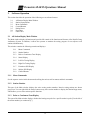
1
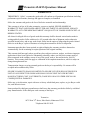
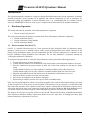
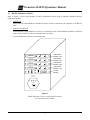
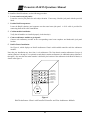
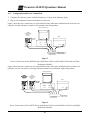
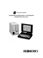
Tremetrics RA650
MICROPROCESSOR GROUP AUDIOMETER
OPERATIONS MANUAL
Tremetrics RA650 Operations Manual
WARRANTY
TREMETRICS, “Seller”, warrants the goods sold will conform to all pertinent specifications including
performance specifications, drawings and approved samples, as furnished.
Seller also warrants said goods to be free of defective materials and workmanship.
This warranty is in lieu of all other warranties, express or implied. SELLER MAKES NO
WARRANTY THAT SAID GOODS ARE FIT FOR ANY PARTICULAR PURPOSE, NOR ANY
WARRANTY AS TO THE MERCHANTABILITY OR QUALITY OF GOODS SOLD EXCEPT AS
HEREIN STATED.
All claims for alleged defects of goods under this warranty shall be deemed waived unless made in
writing and delivered to Seller within twelve (12) months after date of shipment, unless otherwise
specified herein below, and on any such claims, Seller has the option of inspecting the goods claimed
defective at the Buyer’s place of business or having them returned to Seller for inspection.
Instrument parts that have been repaired or replaced during the warranty period are themselves
warranted only for the remaining un-expired portion of the original warranty.
This warranty shall not apply where goods have been subject to misuse, neglect, accident or improper
application or have been repaired or substantially altered by others, nor does this warranty apply to
items consumed in the ordinary course of use of the goods, such as, but not limited to, fuses or
batteries. This warranty shall not apply to calibration of the earphone transducers, which is subject to
change through normal use.
Transportation charges covering returned goods are the buyer's responsibility. No returns will be
accepted unless authorized by Seller.
SELLER’S LIABILITY SHALL BE LIMITED TO SELLER’S STATED SELLING PRICE PER
UNIT OF ANY DEFECTIVE GOODS AND SHALL IN NO EVENT INCLUDE BUYER’S
MANUFACTURING COST, LOST PROFITS, GOOD WILL OR ANY OTHER SPECIAL OR
CONSEQUENTIAL DAMAGES.
Seller may, at its discretion, repair with new or factory refurbished parts, replace, or give Buyer credit
for, such defective items.
Items produced by third party manufacturers shall carry that warranty provided to Seller by said third
party manufacturers. Seller shall pass such warranty to the Buyer.
Tremetrics
9675 West 76th Street, Eden Prairie, Minnesota 55344
Telephone 800-825-0121
i
Tremetrics RA650 Operations Manual
TREMETRICS RA650 AUDIOMETER
This pure tone air conduction Audiometer manufactured by TREMETRICS was designed primarily for
use in determining hearing threshold levels in comparison with standard reference threshold levels. The
Audiometer is a screening device that, if properly operated, maintained, and calibrated, will allow the
operator to screen subjects for shifts in hearing acuity. The Audiometer is used to record the subject’s
current threshold, which may be affected from day to day by noise exposure, colds, sinus infections, or
other problems.
Testing, as referred to in this manual, is the screening procedure used to establish thresholds (hearing
levels) and is in no way trying to diagnose, monitor, or treat any medical problem, disease or injury. If
a problem is suspected, the subject should be referred to an audiologist or medical doctor for
evaluation.
The audiograms obtained from this screening procedure provide a way for records to be maintained for
the subject and for the company where the subject works, in order that an audiologist or medical doctor
may more fully evaluate and prevent major hearing problems.
To guarantee accuracy, each audiometer must be re-calibrated at least once each year and receive an
exhaustive calibration every two years. Daily biological tests through the use of an Electro-Acoustic
Ear (for daily comparisons to acoustic ear baseline obtained at time of calibration) and the operator
listening to each frequency and verifying the attenuator operation, ensures accuracy and purity of the
audiometer tones.
ii
Tremetrics RA650 Operations Manual
Table of Contents
WARRANTY ........................................................................................................................................... i
TREMETRICS RA650 AUDIOMETER................................................................................................. ii
Introduction...............................................................................................................................................1
1. Hardware Operation............................................................................................................................1
1.1 Electro-Acoustic Ear (Oscar™)...................................................................................................1
1.2 RA650 Audiometer Chassis ........................................................................................................2
1.3 RA650 Audiometer Control Module...........................................................................................3
1.4 RA650 Audiometer Module ........................................................................................................3
2. Software Operation .............................................................................................................................4
2.1 All Station Display Main Window ..............................................................................................4
2.2 Station Popup Menu ....................................................................................................................6
2.3 Menu Commands.........................................................................................................................6
2.4 Control Buttons .........................................................................................................................15
2.5 Dialog Boxes .............................................................................................................................16
2.6 Procedures .................................................................................................................................18
2.6.1 Standard Audiometry Test Procedure ....................................................................................18
2.7 Automatic Retest Procedure ......................................................................................................19
2.8 Fault Code Instructions and Responses.....................................................................................19
3. Calibration Procedures......................................................................................................................22
4. Hardware and Software Installation .................................................................................................23
Introduction .........................................................................................................................................23
4.1 Hardware Installation ................................................................................................................23
4.1.1 Configuration and Power Connections ..................................................................................25
4.1.2 Control Module Connections .................................................................................................26
4.1.3 Audiometer Module Connections ..........................................................................................26
4.1.4 Completed Wiring ..................................................................................................................27
4.1.5 Software Installation ..............................................................................................................28
4.1.6 RA650 Chassis Power On ......................................................................................................28
4.1.7 Computer Power On and Boot ...............................................................................................28
4.1.8 Microphone Volume Adjustment...........................................................................................28
4.2 Software Installation..................................................................................................................29
INDEX ....................................................................................................................................................30
iii
Tremetrics RA650 Operations Manual
LIST OF FIGURES
Figure 1 RA650 Audiometer Chassis with Controller and Audiometer Modules....................................2
Figure 2 RA650 Audiometer Control Module..........................................................................................3
Figure 3 RA650 Audiometer Module .......................................................................................................3
Figure 4 RA650 Audiometer Chassis with Controller and Audiometer Modules..................................24
Figure 5 Power Connection, Single RA650 Chassis ..............................................................................25
Figure 6 Power Connection Multiple RA650 Chassis............................................................................25
Figure 7 RA650 Control Module............................................................................................................26
Figure 8 RA650 Audiometer Module .....................................................................................................26
Figure 9 Single RA650 Group Audiometer Chassis...............................................................................27
Figure 10 Multiple RA650 Group Audiometer Chassis .........................................................................27
iv
Tremetrics RA650 Operations Manual
Introduction
This operations manual is intended as a guide in using the RA650 Microprocessor Group Audiometer. It includes
detailed descriptions of the operation of all hardware and software components, as well as procedures for
audiometer testing and calibration. If major difficulties arise, it is recommended that you contact Customer
Service at TREMETRICS. Please be ready to give a complete and accurate detail of the problem encountered.
1.
Hardware Operation
This section describes the operation of the following hardware component:
1.1
Electro-Acoustic Ear (Oscar™)
This section also describes the final pre-operation check of the following three hardware components:
1.2
1.3
1.4
1.1
RA650 Audiometer Chassis
RA650 Audiometer Control Module
RA650 Audiometer Module
Electro-Acoustic Ear (Oscar™)
Oscar™ is a portable Electro-acoustic ear. Oscar performs the daily biological check for audiometer quality
assurance. Oscar serves as a substitute subject with a known hearing threshold level. When connected to the
RA650 Group Audiometer station, the unit automatically provides reference audiogram for comparison to the
baseline established during installation and calibration. The test data establishes a permanent running log
verifying the audiometer’s calibration.
To perform a biological check of a RA650 Group Audiometer station, perform the following procedure:
1. Turn the Oscar power switch to on position.
2. Confirm that the earphone to be tested has the same serial number as the audiometer module to be tested.
3. Place the earphones in the proper coupler on either side of the Oscar, making sure that they are firmly
seated.
Confirm that the left (blue) ear of the earphones is matched with the Left Ear side of the Oscar.
Confirm that the right (red) ear of the earphones is matched with the Right Ear side of the Oscar.
4. Substitute the handswitch cord from the Oscar for the handswitch of the station to be tested.
5. Perform an Electro-acoustic test on the selected station.
6. Save the test for comparison to the baseline audiogram.
7. When testing is complete, turn the Oscar power switch to the off position.
Note: Your biological audiometer check is considered acceptable if the variation in threshold readings is less than
10 dB, deviations of 10 dB or greater are not acceptable. If the difference for any frequency is greater than 10 dB
than inspect the placement of the earphones on the Oscar couplers, ensuring that the cushions are properly seated.
Also ensure that outside noise is not erroneously triggering the Oscar. Re-run the test, then if the problem persists,
you should contact your technical support resource and report the problem. DO NOT USE THE STATION.
The baseline for the Oscar is typically between 60 and 80 dB. This baseline should be established immediately
after audiometer calibration. Battery replacement should occur at the same time. A blinking low battery light
indicates that battery replacement is necessary.
1
Tremetrics RA650 Operations Manual
1.2
RA650 Audiometer Chassis
Refer to Figure 1 below which displays a RA650 Audiometer Chassis with an installed controller and four
audiometer modules.
1. Stations 1-4
Ensure that the Control Module is installed in Chassis A and is connected to the computer via an RS-232
cable.
2. Stations 4-8 (Optional)
Ensure that the Control Module in Chassis A is connected to the Control Module installed in Chassis B
using a cable with RJ-45 connectors attached to the 4+4 jacks.
3. Turn the Audiometer Chassis on/off switch to on.
EARPHONE HANDSWITCH
Audiometer
Module 4 (8)
EARPHONE HANDSWITCH
Audiometer
Module 3 (7)
EARPHONE HANDSWITCH
Audiometer
Module 2 (6)
EARPHONE HANDSWITCH
Audiometer
Module 1 (5)
SERIAL NO.
XXXX-XXXXX
SERIAL NO.
XXXX-XXXXX
SERIAL NO.
XXXX-XXXXX
SERIAL NO.
XXXX-XXXXX
MIC
MSG
LINE
MIC
PWR
4x4
COMPUTER
RJ-45
RS-232
Control
Module
90-240 VAC
50-60 Hz
ON
OFF
Figure 1
RA650 Audiometer Chassis with Installed Controller
and Four Audiometer Modules
2
Tremetrics RA650 Operations Manual
1.3
RA650 Audiometer Control Module
Refer to Figure 2 below which displays a RA650 Audiometer Control Module.
1. Stations 1-4
Ensure that the Control Module is installed in Chassis A and is connected to the computer via an RS-232
cable.
2. Stations 4-8 (Optional)
Ensure that the Control Module in Chassis A is connected to the Control Module installed in Chassis B
using a cable with RJ-45 connectors attached to the 4+4 jacks.
3. Ensure that the Line jack is connected to the multimedia connector on the computer.
4. Ensure that the MIC jack is connected to the microphone.
5. Use a screwdriver to adjust the microphone volume at the MIC set screw.
6. Confirm that the MSG and PWR lights are working.
MSG
MIC
LINE
MIC
PWR
4x4
COMPUTER
RJ-45
RS-232
Figure 2
RA650 Audiometer Control Module
1.4
RA650 Audiometer Module
Refer to Figure 3 below which displays a RA650 Audiometer Module.
1. Confirm that the Audiometer Serial Number matches the headphone serial number.
2. Confirm that the Earphone with the same serial number is plugged into the Earphone jack.
3. Confirm that the station Handswitch is plugged into the Handswitch jack and activates the LED for the
Audiometer module.
4. Repeat Steps 1 through 3 for each station audiometer module.
RESPONSE
EARPHONE
SERIAL NO.
XXXX-XXXXX-XXX
Figure 3
RA650 Audiometer Module
3
HANDSWITCH
Tremetrics RA650 Operations Manual
2.
Software Operation
This section describes the operation of the following seven software features:
2.1
2.2
2.3
2.4
2.5
2.6
2.7
2.1
All Station Display Main Window
Station Popup Menus
Menu Commands
Control Buttons
Dialog Boxes
Procedures
Fault Codes
All Station Display Main Window
The Main window displays all stations and provides full control of the functions and features of the RA650 Group
Audiometry System. In addition, it allows the operator to monitor the testing progress of test subjects at all
stations simultaneously.
This window contains the following controls and displays:
2.1.1
2.1.1
Menu Commands
2.1.2
Station Number
2.1.3
Pulse or Continuous Tone Display
2.1.4
Status Display
2.1.5
Left Ear Testing Display
2.1.6
Right Ear Testing Display
2.1.7
Examiners SSN Display
2.1.8
Subject SSN Display
2.1.9
Control Buttons
Menu Commands
See the separate section in this document describing the various tool bar menus and their commands.
2.1.2
Station Number
This part of the Main window displays the active testing station numbers. Inactive testing stations are shown
grayed out. You can right-click the mouse button on any active station number to display the Station Popup menu,
which allows you to select station-specific functions.
2.1.3
Pulse or Continuous Tone Display
This part of the Main window displays whether the hearing test pulse for a specific station is pulse [P to the left of
the station number] or continuous [C].
4
Tremetrics RA650 Operations Manual
2.1.4
Status Display
This part of the Main window displays the current status of a specific testing station. At any time, each station has
one of the following statuses:
Offline
The station has been removed from the list of available testing stations.
Paused
The station is in a temporary pause state.
Reset
This station has just been reset and is ready for the next hearing test.
Testing
This station is currently testing a subject.
Saved
This hearing test data for this station has been saved.
Error
An error condition has occurred at the station. See Fault Code Instructions and Responses for
further explanation.
2.1.5
Left Ear Testing Display
The left ear is usually tested first, then the right ear. This display allows you to monitor the hearing thresholds at
each frequency as data are captured automatically by the RA650 system. As the test proceeds, the AA in the
screen changes to the level being tested. For example the level detected for station 1 may be 35 dB at 1K (1000
Hz). A level displayed with a green background signifies, a bad, or no response at that level, while a blue
background signifies a good response. The operator can monitor the progress of the test. As thresholds are
established, the results are stored for the frequency specified. The test results usually proceed from left to right on
the display. However, the right ear can be tested first by using the “Right Ear First” command from the Stations
menu.
2.1.6
Right Ear Testing Display
See Left Ear Testing Display above.
2.1.7
Examiners SSN Display
The examiner must enter his or her social security into the database before saving a test. To change the current
social security number, left-click the mouse button on the Examiners SSN text box to open the Enter Examiners
SSN dialog box.
2.1.8
Subject SSN Display
The social security number of each test subject must be entered into the test records prior to the saving of a
hearing test. To change the current social security number, left-click the mouse button on the station number to
the left of the subject social security number to open the Enter SSN for Station dialog box.
2.1.9
Control Buttons
See separate section in this document containing descriptions of the various Control Button functions.
5
Tremetrics RA650 Operations Manual
2.2
Station Popup Menu
This popup menu is activated by right-clicking the mouse button on one of the station numbers, [1-8] in the Main
window. The following commands in the menu are then active only for the selected testing station:
Commands
Function Key
Start/Resume
F2
Play and Start
F4
Pause
F6
Talk-over
F5
Reset
F8
Save
F10
Print
F11
Restart
F7
Manual
F9
Enter Data
F3
Enable/Disable Station
Daily Biological:
2.3
Menu Commands
The following menus are provided in the RA650 operating software:
2.3.1
2.3.2
2.3.3
2.3.4
2.3.5
2.3.6
File Menu
Edit Menu
Functions Menu
Setup Menu
Calibrate Menu
Help Menu
6
Tremetrics RA650 Operations Manual
2.3.1
File Menu
The File menu provides the following commands:
Command
Shortcut
Key
Function
Print command
F11
This command prints a report of the stations that are currently being tested.
Use the Print Setup command to open the Print Setup dialog box so that you
can set printing parameters.
Allows you to set printer type, orientation, paper size, and paper source.
Print Setup
command
Allows you to close the RA650 software application.
Exit command
2.3.2
Edit Menu
The Edit menu provides the following commands:
Command
Cut command
Shortcut
Key
Function
Not active at this time.
Copy command
Not active at this time.
Paste command
Not active at this time.
7
Tremetrics RA650 Operations Manual
2.3.3
Functions Menu
The Functions menu provides the following commands:
Command
Shortcut
Key
Start/Resume
command
F2
Play and Start
command
F4
Pause command
F6
Function
Starts the audiometry test, for all test subjects. or resumes all paused
audiometer tests.
Alternatively, you can use the Start/Resume button. Double-clicking the left
mouse button on the desired station will also start or resume a test.
Allows you to play multimedia instructions prior to the start of a test. When
the instructions are completed the hearing test is initiated.
Temporarily stops the selected audiometry test(s). This command can be
used if a problem occurs during the administration of one or more audiometry
tests.
Alternatively, you can use the Pause button. Double-clicking the left mouse
button on the desired station will also pause a specific test in progress.
F5
Pauses the test and allows you to talk over the microphone to a single
audiometry test subject.
Talk-over All
command
Alt + F5
Pauses the test and allows you or the multimedia to talk over the microphone
to all audiometry test subjects simultaneously.
Reset command
F8
Talk-over
Individual
command
Alternatively, you can use the Talk Over All button.
Clears all subject information and all audiometry testing information so that
you can start another group of subjects.
Alternatively, you can use the Reset button.
Save Test
command
Restart command
Manual command
F10
Allows you to save the current audiometry test data to the computer hard
drive.
F7
Resets audiometry test data for the selected test subjects, but does not change
subject information that has been previously entered. Alternatively, you can
use the Restart button.
F9
Allows you to administer the hearing test manually. This is accomplished by
specifying the ear, frequency, and initial presentation level. You can use the
keyboard or mouse, to present the first tone. You can also initiate subsequent
tones. The level of the tone is a function of the response of the subject in
accordance with the Hughson Westlake procedure. Test completion is
indicated on the Main window and the HTL is stored with an M to indicate
that the test results were derived using the manual method.
8
Tremetrics RA650 Operations Manual
Enter Data
command
F3
Allows you to enter social security information for test subjects.
This command allows you to print a hearing test report.
Print command
Use the Print Setup command to open the Print Setup dialog box so that you
can set printing parameters.
Retrieve Status
command
Allows you to display all data from all stations.
Check All Stations
command
Allows you to verify that a station is installed in the module chassis.
9
Tremetrics RA650 Operations Manual
2.3.4
Setup Menu
The Setup menu provides the following commands:
Command
Shortcut
Key
Function
Allows you to conduct group test in a common sound room.
Group Testing
Command
If this command is enabled, a check mark appears to the left of the menu
command. If this command is disabled, no check mark appears to the left of
the menu command.
Allows you to administer the hearing test with either pulsed or continuous
tones sent to the earphones.
This command is a toggle between the two modes of operation.
Pulsed /
Continuous
Command
The pulsed tone character is 0.2 second on and 0.2 second off, corresponding
to a 50% duty cycle with three pulsed tone presentations.
The continuous tone character is 1.0 seconds in duration.
If pulsed is enabled, a check mark appears to the left of the menu command.
If continuous is enabled, no check mark appears to the left of the menu
command.
Delete 8K
Command
Right Ear
First command
Enable / Disable
Station Command
Allows you to delete the 8,000 Hz (8K Hz) part of the hearing test. This
effectively reduces the time required to administer the hearing test.
If this command is enabled, a check mark appears to the left of the menu
command.
This command results in a test subject’s right ear being tested first, followed
by testing of the left ear. This is the opposite of normal convention.
If the Right Ear First is enabled, a check mark appears to the left of the menu
command.
This command allows you to remove an enabled station from the testing
group or to add a previously disabled station to the testing group. This
ensures that no sounds are emitted from unused headphones during group
testing.
If the Stations are enabled, a check mark appears to the left of the menu
command.
10
Tremetrics RA650 Operations Manual
Set Lower HTL to
00 dB command
Adaptive Mode
Command
Check and
Retest on:
Adjacent
Frequencies
command
HTL ≥ 90dB or
500 Hz ≥ 30 dB
command
Contralateral
of 40 dB
command
STS of 15 dB
Command
Sets the lower hearing threshold level tested to 00 dB, instead of –10 dB.
If 00dB is the lowest level to test, a check mark appears to the left of the
menu command.
Automatically extends the length of the hearing test to accommodate slow
responses. This mode increases the response acceptance window time.
If Adaptive is enabled, a check mark appears to the left of the menu
command.
Activates a switch that enables or disables the comparison of adjacent
frequencies looking for a difference of 50 dB or greater. If the difference is
greater than 50 dB, the frequency of the higher HTL of the adjacent
frequencies is re-tested. An EC Error is displayed and the frequency in error
is automatically re-tested.
Allows you to automatically retest the subject in the event that the HTL was
equal to or greater than 90 dB for any frequency. This result will generate a
ED Error condition.
This command allows you to also automatically retest the subject in the event
that the HTL was greater than or equal to 30 dB at 500 Hz. This result will
generate a ED Error condition.
Activates a switch that compares the HTL for the same frequency of the
opposite ear and, if greater or equal to 40 dB, then the higher level is retested. An EA Error is displayed and the frequency is re-tested
automatically.
Compares the levels of the current hearing test to the reference baseline
hearing of the subject. If the baseline data is stored with the subject
demographics, the baseline data is downloaded to the audiometer when you
enter the subject’s social security number. An EB Error is displayed if the
difference between the current test and the baseline data is 15 dB or greater.
If any of these commands is enabled, a check mark appears to the left of its
menu command. If any of these commands is disabled, no check mark
appears to the left of its menu command.
Multimedia:
Play Instructions
on Error command
Error Handling:
Military Error
Processing
command
Automatically plays an error-specific multimedia recording when an error
occurs during a test.
If this command is enabled, a check mark appears to the left of the menu
command. If this command is disabled, no check mark appears to the left of
the menu command.
Allows you to enter the number of times that a prerecorded message will be
played.
11
Tremetrics RA650 Operations Manual
Process Errors in
Manual Mode
command
Activates multimedia announcements while operating in manual mode.
Reset Error Count
on Error Test
command
Allows you to specify the number of times that the system will automatically
start after a station error.
Frequency Order
command
Not used at this time.
RS232
Configuration
command
Timing
Parameters
command
Station Summary
command
Allows you to specify the Com Port that is being used.
Not used at this time.
Displays station diagnostic messages.
12
Tremetrics RA650 Operations Manual
2.3.5
Calibrate Menu
The Calibrate menu provides the following commands:
Command
Acoustic:
Calibration
command
Verification
command
Shortcut
Key
Function
Allows you to calibrate each audiometer module.
Allows you to test the rise and fall times of each tone as it is turned on and
off, the linearity of the audiometer attenuation from 100 dB to -10dB, check
the total harmonic distortion signal (tone) on to off ratio, and check the
crosstalk from one ear to the other ear.
Remote
Verification
command
Allows you to verify the operation of an audiometer channel from the sound
room (remotely). The audiometer module will automatically step through a
70 dB test tone frequency sequence, starting at 500 Hz. Activation of the
handswitch steps to the next tone of the verification sequence.
Daily Biological:
Run Test
Disables the check for HTL over 30 dB. This is intended for the daily
verification of the audiometer.
Functional
command
Performs part of the daily check. The technician listens for unusual clicks or
noises in the earphone at a listening station. Each time the handswitch is
depressed, the frequency of the tone changes.
Memory
command
Requests that the selected audiometer module station performs a RAM and
ROM memory test. If the system is operating correctly, nothing is
displayed. If a problem is detected, an E8 message is displayed for the
station with the memory problem.
13
Tremetrics RA650 Operations Manual
2.3.6
Help Menu
The Help menu provides the following commands:
Command
Shortcut
Key
Function
Contents
command
F1
Opens RA650 Group Audiometer online Help at the Contents tab. You can
then use the contents, index, or find functions to find the topic(s) of interest.
Search for Help
On command
Opens RA650 Group Audiometer online Help at the Find tab. You can then
use the find function to find topic(s) of interest by searching all online Help
topics.
How to Use Help
command
Opens a Help file that describes how to use the Online Help provided with
your RA650 Group Audiometer System.
On Main
Window
About
Opens a Help file that describes the main window functions and features.
Displays RA650 developed by Tremetrics, Version number, and copyright
message.
14
Tremetrics RA650 Operations Manual
2.4 Control Buttons
The following control buttons are provided in the RA650 operating software:
2.4.1
2.4.2
2.4.3
2.4.4
2.4.5
2.4.6
2.4.1
Start/Resume button
Pause button
Reset button
Restart button
Talk Over All button
Talk Over Each button
Start/Resume button
This button starts the audiometry test for all test subjects or resumes all paused audiometer tests. Alternatively,
you can use the Functions | Start/Resume command, or the F2 key.
2.4.2
Pause button
This button temporarily stops the selected audiometry test(s). This command can be used if a problem occurs
during the administration of one or more audiometry tests. Alternatively, you can use the Functions | Pause
command, or the F6 key.
2.4.3
Reset button
This button clears all subject information and all audiometry test information so that you can start another group
of subjects. Alternatively, you can use the Functions | Reset command, or the F8 key.
2.4.4
Restart button
This button resets audiometry test data for the selected test subjects, but does not change subject information that
has been previously entered. Alternatively, you can use the Functions | Restart command, or the F7 key.
2.4.5
Talk-Over All button
This command allows you to talk over the microphone to all audiometry test subjects simultaneously.
Alternatively, you can use the Functions | Talk Over Group command, or the Alt-F5 key combination.
2.4.6
Talk-Over Each button
This button allows you to talk over the microphone to a single audiometry test subject. Alternatively, you can use
the Functions | Talk Individual command, or the F5 key.
15
Tremetrics RA650 Operations Manual
2.5 Dialog Boxes
The following dialog boxes are provided in the RA650 operating software:
2.5.1
2.5.2
2.5.3
2.5.4
2.5.5
2.5.1
Calibrating Station #[ ] dialog box
Calibration dialog box
Enter Examiners SSN dialog box
Enter SSN for Station #[ ] dialog box
Select a Subject dialog box
Calibrating Station #[ ] dialog box
Refer to the RA650 Microprocessor Group Audiometer Service Manual.
2.5.2
Calibration dialog box
Refer to the RA650 Microprocessor Group Audiometer Service Manual.
2.5.3
Enter Examiners SSN dialog box
This dialog box allows you to enter the social security number of the current hearing test examiner into the
database records.
The Enter Examiners SSN text box displays the social security of the current examiner. To change the current
social security number, type the social security number using the format xxx-xx-xxxx into the text box.
Alternatively, left-click the button beside the SSN dialog box to select an Examiner from the Examiner database.
The Examiner must already be in the database to be selected in this way. Choose OK when you have completed
your entry.
2.5.4
Enter SSN for Station #[ ] dialog box
This dialog box allows you to enter the social security number of the hearing test subject assigned to a specific
testing station and to enter the purpose of the hearing test examination into the subject’s records.
The Enter SSN for Station #[ ] text box displays the social security of the subject assigned to the selected testing
station. To change the current social security number, type the social security number using the format xxx-xxxxxx into the text box. Alternatively, click on the text box to open the Select a Subject dialog box so that you can
select a previously entered subject by Last Name, First Name, or Social Security Number. To be a valid entry, the
subject SSN must already be in the database. Choose OK when you have completed your entry.
The Enter SSN for Station #[ ] dialog box also includes a section which allows you to enter the purpose of the
exam. The following Purpose of Exam selection option buttons are offered:
16
Tremetrics RA650 Operations Manual
Symbol
Name
A
Annual option button
B
Reference Baseline
option button
To complete a hearing baseline test in which future hearing tests will
be compared.
1
Follow-Up No. 1
option button
To complete a hearing test as a follow up to a previous incident or test.
2
Follow-Up No. 2
option button
To complete a hearing test as a second follow up to a previous incident
or test.
9
90 Day
option button
R
Re-established Baseline
option button
To complete a new hearing baseline test in which future hearing tests
will be compared.
E
Reference Following
Exposure option button
To complete a new hearing baseline reference test in which future
hearing tests will be compared.
T
Termination option
button
To complete a final hearing test upon the completion of an assignment
and subsequent termination of a position.
O
Other option button
To complete a hearing test for a reason not covered by the other
options in this list of option buttons.
OK option button
Select the OK button to store the selected options and close the current
dialog box.
Cancel option button
Select the Cancel button to ignore all entries and to return to the
previous dialog box or window.
2.5.5
Purpose of Exam
To complete an annual hearing test.
To complete a hearing test every 90 days.
Select a Subject dialog box
This dialog box allows you to select the Last Name, First Name, and Social Security Number of a test subject who
has been entered into the hearing test database. The alternative entry method is to enter the social security number
using the Enter SSN for Station #[ ] dialog box. Scroll to select a subject and choose the Select button.
17
Tremetrics RA650 Operations Manual
2.6 Procedures
This section describes the procedures for the following audiometer tests:
2.6.1
2.6.2
2.6.3
Standard Audiometry Test
Automatic Retest
Daily and Yearly Calibrations
It also includes a description of the Fault Codes that may arise during audiometer testing, and the appropriate
operator responses.
2.6.1
Standard Audiometry Test Procedure
1.
Prepare for next test subjects:
SAVE THE CURRENT TEST. Then, click on the Reset button to clear all previous data and get ready
for the next hearing tests. Tests can be started at this time.
2. Enter operator’s social security number:
Left-click the mouse button on the Examiners SSN number displayed in the Main window to open the
Enter Examiners SSN dialog box. Enter your social security number in the Examiner SSN text box.
Choose OK to save your entry.
The new examiner’s social security number is displayed in the Main window.
3. Enter subject’s social security number and purpose of exam:
Left-click the mouse button on 000-00-0000 to the right of the subject’s assigned station number to
open the Enter SSN for Station [ ] dialog box. Enter the subject’s social security number in the Station
SSN text box (The SSN must already be entered in the database.) and select the appropriate Purpose of
Exam option button. Repeat as required for other subjects.
Alternatively, you can select the number from the database. Left-click the mouse button on the Station
SSN text box to open the Select a Subject dialog box. Scroll to the appropriate row and click to select
the subject’s Last Name, First Name, and Social Security Number. Choose the Select button to save the
selection and return to the Enter SSN for Station [ ] dialog box.
Choose OK to save entries and return to the Main window.
The new subject’s social security number is displayed. Repeat as required for other subjects at other
stations.
4. Talk to test subjects:
Click the Talk-over all button, or select Functions | Play and Start, to provide instructions to all
testing subjects.
5. Start hearing test:
Click the Start button to start all hearing tests.
6. Monitor test:
Monitor the progress of all tests.
7. Respond to problems:
Respond to error codes and problems.
8. Retest as required:
Provide special additional testing, as required.
9. Save test data:
Select Functions | Save to save all data for the testing group.
10. Store data in Hears database:
Select Functions | Print to save all data to the Hears Database.
18
Tremetrics RA650 Operations Manual
2.7 Automatic Retest Procedure
2.7.1
Automatic Retest Criteria
The RA650 Group Audiometer automatically performs a retest of the subject under the following circumstances
(if Check and Retest has been selected):
•
Error EB - A threshold change of ± 15 dB HTL or greater occurs at any frequency, during testing,
relative to the reference.
•
Error ED - Any frequency has an HTL of 90 dB or greater.
•
Error ED - The HTL at 500 Hz is greater than 30 dB.
•
Error EA - There is an HTL difference of 40 dB or more between ears at the same frequency.
•
Error EC - There is a difference of 50 dB or greater for an adjacent frequency.
2.8 Fault Code Instructions and Responses
A fault code is an immediate warning, including both an on screen visual and auditory signal. The intensity of the
auditory signal is controlled by the RA650 Group Audiometer.
A fault code is generated under the following conditions:
•
Error E1 - A listener response is not obtained for the first ear tested at 1000Hz.
•
Error E2 - There is no validation for the first test ear response at 1000 Hz. This can occur if too much
time has elapsed without achieving threshold validation.
•
Error E3 - The first ear fails the 1000 Hz re-test. A validity check is performed by testing each ear twice
at 1000 Hz. The threshold values must be within ± 5 dB. If this is achieved, the lower of the
two threshold levels is retained. If this is not achieved, the test is stopped, the technician is
summoned, and the entire test is repeated.
•
Error E4 - There is no release of the hand switch button.
•
Error E5 - More than one response per frequency is given without additional tone presentations.
•
Error E6 - The retest did not validate the HTLs at the required one or two frequencies. A maximum of
20 tone presentations or 60 seconds are allowed at each test frequency.
•
Error E7 - There is no validation of HTLs at three frequencies.
For each of the above errors, the appropriate operator responses, either through Talk-over or the multimedia
function provides additional instructions to the test subject, as follows:
Error E1:
No Response at 1000 Hz. Test
Instructions: “You are not pushing the handswitch when you hear the tone. I will restart the test, remember
to push and release the handswitch as soon as you hear the tone.”
Error E2:
No validation of 1000 Hz. Test
Instructions: “Press and release the handswitch button as soon as you hear a tone, even if the tone is very
soft.”
19
Tremetrics RA650 Operations Manual
Error E3:
Failed 1000 Hz. Retest.
Instructions: (Single Test; First Time, First Ear) “Press and release the handswitch button as soon as you
hear a tone, even if the tone is very soft.”
Response: Start the test over.
(Single Test; First Time, Second Ear) “Press and release the handswitch button as soon as
you hear a tone, even if the tone is very soft.”
(Single Test; Second Time, Second Ear) “Press and release the handswitch button as soon as
you hear a tone, even if the tone is very soft.”
Response: Start the test over.
(Group Test; First Time, First Ear) “Sit quietly and I will retest you when the group finishes.
Press and release the handswitch button as soon as you hear a tone, even if the tone is very
soft.”
Response: Start the test over.
(Group Test; Second Time, Second Ear) “Sit quietly and I will retest you when the group
finishes. Press and release the handswitch button as soon as you hear a tone, even if the tone
is very soft.”
Response: Start the test over.
Error E4:
No release of handswitch button.
Instructions: “You are not releasing the handswitch quickly enough. Remember to press and release the
handswitch quickly, as soon as you hear the tone.”
Error E5:
Responding when no tone is present.
Instructions: “You are pushing the handswitch when no tone is present. Be sure you hear the tone and press
and release your handswitch quickly.”
Error E6:
No validation on one or two frequencies.
Instructions: None.
Response: Switch to manual mode and administer a manual test at the missed frequencies.
Error E7:
Failed to validate at three frequencies.
Individual Instructions: None.
Response: Re-instruct the individual on the entire test procedure. Press the Reset button, then press
Start. You will need to reassign the individual to a station.
Group Instructions: “Sit quietly and I will retest you when the group finishes.”
Response: Re-instruct the individual on the entire test procedure. Press the Reset button, then press
Start. You will need to reassign the individual to a station.
20
Tremetrics RA650 Operations Manual
Error EA: Contralateral of 40 dB recorded.
Response: Will not stop the test. Automatically re-tested at the end of the test.
No operator intervention required.
Error EB: Difference between the current test and baseline data is ≥ 15 dB.
Response: Will not stop the test. Automatically re-tested at the end of the test.
No operator intervention required.
Error EC: Difference between adjacent frequencies is ≥ 50 dB.
Response: Will not stop the test. Automatically re-tested at the end of the test.
No operator intervention required.
Error ED: HTL ≥ 90 dB. or 500 Hz ≥ 30 dB.
Response: Will not stop the test. Automatically re-tested at the end of the test.
No operator intervention required.
Error EE: No responses at frequencies other than 1000 Hz. Test.
Response: Will not stop the test. Automatically re-tested at the end of the test.
No operator intervention required.
Error EF: No validation at frequencies other than 1000 Hz. Test.
Response: Will not stop the test. Automatically re-tested at the end of the test.
No operator intervention required.
Error NR: No response at any level of frequency presented.
21
Tremetrics RA650 Operations Manual
3. Calibration Procedures
Two different types of calibration procedures should be performed on the RA650 Audiometer, Biological
Calibration and Acoustical Calibration.
3.1
Biological Calibration
Biological Calibration provides an electronic calibration monitor that tests the acoustic output of each test station
for 500 to 8000 Hz, inclusive. Calibration is provided with the Tremetrics Oscar™ instrument. See the section in
this document, which describes the operation of the Electro-acoustic ear Oscar. Also the operator, to verify pure
tones without odd or distorted sounds should perform a daily functional check.
3.2
Acoustical Calibration
Acoustical Calibration is a password protected calibration mode in which the earphones are controlled using a 70
dB continuous tone beginning at 500 Hz.
The calibration date in YYMMDD format is required before the calibration is completed. Y=year, M=month, and
D=day.
Certified calibration should be performed approximately once per year or as required. This procedure requires the
use of a calibrated sound level meter.
Note: Only qualified personnel should perform this calibration procedure.
See the RA650 Microprocessor Group Audiometer Service Manual for this procedure.
22
Tremetrics RA650 Operations Manual
4. Hardware and Software Installation
Introduction
This installation manual provides a qualified technician with sufficient information for the installation of both the
hardware and the software components of the RA650 Microprocessor Group Audiometer. If major problems are
encountered, it is recommended that the technician contact Customer Service at TREMETRICS, giving complete
and accurate details; such as serial number, date of purchase, description of part, and TREMETRICS part number.
The reader should refer to the illustrations of this manual to aid in the installation process.
4.1
Hardware Installation
The RA650 Group Audiometer System should be installed in a well-lighted, well-ventilated area near the
audiometric sound room. The table space required for a 4-station installation is five feet by three feet. The table
space required for an 8-station installation is six feet by three feet.
The RA650 requires power connection to 90-264 VAC at 47 to 63 Hz with a 500 VA (voltage/ampere) rating.
The power receptacle should be marked “Hospital Grade” or “Hospital Only” to comply with safety regulations.
Outside the continental United States, usage must comply with European standards.
Hardware requirements for the RA650 Group Audiometer System are as follows:
Computer:
IBM compatible PC (486 or higher)
8 MB RAM
340 MB hard drive
3.5” floppy drive
EGA/VGA monitor
Keyboard
Mouse
Windows Office Professional
An available communication port (to communicate with the RA650)
Printer:
A parallel printer is required to print reports.
23
Tremetrics RA650 Operations Manual
To install the RA650 hardware, use the following procedure:
1. Locate sound room jack panels:
Locate the exterior jack panels for each subject location. If necessary, label the jack panel with the provided
labels.
2. Position RA650 components:
Locate the RA650 chassis(s) and computer near the sound room jack panel. A 30-ft. cable is provided for
connecting the RA650 to the Sound Room.
3. Confirm module installation:
Verify that all modules are installed properly in the chassis(s).
4. Connect audiometer modules to jack panel:
Connect each audiometry module to the corresponding sound room earphone and handswitch jack panel
location.
5. RA650 Chassis Installation:
See Figure 4, which displays an RA650 Audiometer Chassis with installed controller and four audiometer
modules.
Note that your installation may have from 1 to 8 audiometers. The first chassis contains audiometers for up to 4
stations (Stations 1 through 4). An optional second chassis contains audiometers for additional stations (Stations 5
through 8). Also note that the station number is defined by the location of the audiometer in the RA650 chassis, as
shown in the figure 4.
EARPHONE HANDSWITCH
Audiometer
Module 4 (8)
EARPHONE HANDSWITCH
Audiometer
Module 3 (7)
EARPHONE HANDSWITCH
Audiometer
Module 2 (6)
EARPHONE HANDSWITCH
Audiometer
Module 1 (5)
SERIAL NO.
XXXX-XXXXX
SERIAL NO.
XXXX-XXXXX
SERIAL NO.
XXXX-XXXXX
SERIAL NO.
XXXX-XXXXX
MIC
MSG
LINE
MIC
PWR
4x4
COMPUTER
RJ-45
RS-232
Control
Module
90-240 VAC
50-60 Hz
ON
OFF
Figure 4
RA650 Audiometer Chassis with Installed Controller and Four Audiometer Modules
24
Tremetrics RA650 Operations Manual
4.1.1
Configuration and Power Connections
1. Configure the computer, printer, and RA650 hardware, as shown in the following figures.
2. Plug in each component, but do not turn them on at this time.
Figure 5 shows the power connections of a typical RA650 Group Audiometer installation with one chassis, one
controller, and four audiometer modules to accommodate four testing stations.
Computer and Monitor
RA650
Microprocessor
Audiometer
Rack 1
Printer
4
3 Audiometer
2 Modules
1
COM 1
LPT 1
Power Strip with
Surge Protection
To 90-240 VAC
50-60 Hz Outlet
Figure 5
Power Connections of One RA650 Group Audiometer Chassis with Installed Controller and Four
Audiometer Modules
Figure 6 shows the power connections of a typical RA650 Group Audiometer installation with two chassis, two
controllers (one for each chassis), and eight audiometer modules to accommodate eight testing stations.
Computer and Monitor
RA650
Microprocessor
Audiometer
Rack 2
8
7
6
5
RA650
Microprocessor
Audiometer
Rack 1
Printer
4
3 Audiometer
2 Modules
1
COM 1
LPT 1
Power Strip with
Power Strip with
Surge Protection
Surge Protection
To
ACVAC
Outlet
To 110v
90-240
50-60 Hz Outlet
Figure 6
Power Connections of Two RA650 Group Audiometer Chassis with Installed Controllers and Eight
Audiometer Modules
25
Tremetrics RA650 Operations Manual
4.1.2
Control Module Connections
Figure 7 presents an illustration of the RA650 Audiometer Control Module.
1. Connect the 9-pin RS-232 cable from the Control Module on RA650 Chassis 1 to the available
communication port on the computer.
2. Connect the stereo multimedia cable from the RA650 Control Module Line jack to the sound card on the
computer, if the sound card is available.
MSG
MIC
LINE
MIC
PWR
4x4
COMPUTER
RJ-45
RS-232
Figure 7
RA650 Control Module
3. Connect the microphone cable to the MIC jack on the RA650 control module.
4. Optional. If you are installing two RA650 chassis to accommodate more than four testing stations, connect
the RJ-45 cable from the 4+4 RJ-45 port on the control module of Chassis 1 to the 4+4 RJ-45 port on the
control module of Chassis 2.
4.1.3
Audiometer Module Connections
Figure 8 displays the RA650 Audiometer Module.
1. Connect the Earphones and Handswitches to their respective jacks in each of the sound rooms. Ensure that
the station number tag on each handswitch (HS #X) and earphone (EAR #X) wire (from Step 3) correlates
with the audiometer module station number, as defined by the placement in the RA650 chassis(s).
RESPONSE
EARPHONE
HANDSWITCH
SERIAL NO.
XXXX-XXXXX-XXX
Figure 8
RA650 Audiometer Module
Note: Each set of earphones must be matched to its respective audiometer. Match the Serial Number tag on
each audiometer to the Serial Number tag on each earphone package. Assign each earphone to the corresponding
testing station.
26
Tremetrics RA650 Operations Manual
4.1.4
Completed Wiring
Figures 9 and 10, below, illustrate all connections of a typical RA650 Group Audiometer. Installation with one
chassis, one controller, and four audiometer modules to accommodate four testing stations, and all connections of
a typical RA650 Group Audiometer installation with two chassis, two controllers, and eight audiometer modules
to accommodate eight testing stations.
Computer and Monitor
RA650
Microprocessor
Audiometer
Rack 1
4
3 Audiometer
2 Modules
1
Microphone
Printer
COM 1
LPT 1
Line
To Sound
Room
Stations 1-4
Power Strip with
Surge Protection
To 110v AC Outlet
Figure 9
Complete Connections of One RA650 Group Audiometer Chassis with Installed Controller and Four
Audiometer Modules
Computer and Monitor
RA650
Microprocessor
Audiometer
Rack 2
RA650
Microprocessor
Audiometer
Rack 1
8
7
6
5
Printer
4
3 Audiometer
2 Modules
1
COM 1
To Sound
Room
Stations 5-8
To Sound
Room
Stations 1-4
LPT 1
Power Strip with
Surge Protection
To 110v AC Outlet
Figure 10
Complete Connections of Two RA650 Group Audiometer Chassis with Installed Controllers and Eight
Audiometer Modules
27
Tremetrics RA650 Operations Manual
4.1.5
Software Installation
Install the RA650 operating software as directed in the Software Installation section of this manual.
4.1.6
RA650 Chassis Power On
Turn on power to the RA650 Chassis(s) using the power switch in the back. Confirm that the PWR light on the
Control Module(s) comes on.
4.1.7
Computer Power On and Boot
1. Turn on power to the computer, monitor, and printer. The computer should boot and the Windows
95/98/ME/XT starting screen should appear.
2. Because the RA650 is Plug-and-Play compatible, the computer should recognize that the RA650 is on line
and ask that the driver be loaded. (This should happen only once.)
3. Use the Start button to navigate to the RA650 program, and double-click to start the RA650 software
program. Alternatively, double-click on the earphone icon. The RA650 main control window will appear.
4. The RA650 software will locate all installed audiometers and display each installed station on the screen.
Note that the assigned station number is defined by the placement of each RA650 audiometer in its RA650
chassis.
4.1.8
Microphone Volume Adjustment
1. Turn on Talk-Over using the RA650 software.
2. Plug in the matching earphone to a station and speak into the microphone. Use a screwdriver to adjust the
volume using the MIC adjustment.
3. Turn clockwise to turn volume up and counter-clockwise to turn volume down.
4. Repeat to confirm volume level for all stations.
5. Use Operation instructions to perform audiometer testing.
28
Tremetrics RA650 Operations Manual
4.2 Software Installation
Note: The diskettes that are used with the computer warrant special considerations. The disks are covered in a
flexible housing for protection. Nevertheless, they can vary in quality so the prudent user will always use the very
highest quality diskettes. Do not store the diskettes in an area near magnets or large motors. Always store them in
their proper containers. Even with these precautions, data on the disks can be destroyed, so be sure to use your
computer to make backup copies (copy to another disk) of the installation disks. These limited precautions, if
followed, will help to ensure good results with your computer system.
Completion of the RA650 Group Audiometer system installation requires one of the following operating systems:
Windows 95/98/ME/XT
or Windows NT 4.0 / Windows 2000
To install the RA650 software, use the following procedure:
1. Insert the RA650 software disk.
2. From the Windows Start Menu, click Run.
3. Type into the window D:\SETUP. (where “D” is the letter of your CD ROM drive.)
4. The Setup program will automatically start and prompt you through the remainder of the installation process.
29
Tremetrics RA650 Operations Manual
INDEX
90 Day option button
17
Enable/Disable Station command
Acoustical Calibration
22
Enter Data command
Adaptive Mode command
11
Enter Examiners SSN dialog box
16, 18
Adjacent Frequencies command
11
Enter SSN for Station #[ ] dialog box
16, 17
Annual option button
17
Error
audiometer module
1, 2, 3
Audiometer Module
2, 3
audiometer modules
Automatic Retest
6, 9
5, 11, 12, 19, 20, 21
Examiners SSN
5
Exit command
7
Fault Code
25, 27
6, 10
4, 5, 18, 19
File Menu
19
7
1, 17
Follow-Up No. 1 option button
17
Biological Calibration
22
Follow-Up No. 2 option button
17
Calibrate Menu
13
Frequency Order command
12
Calibrating Station #[ ] dialog box
16
Functional command
13
Calibration command
13
Functions Menu
Calibration dialog box
16
Group Testing command
Cancel option button
17
handswitch
baseline
Check All Stations command
8
10
1, 19, 20, 26
Handswitch jack
9
3
23, 28
hardware
23, 24, 25
Contents command
14
Hardware
23
Contralateral of 40 dB command
11
Help Menu
14
How to Use Help command
14
HTL ≥ 90dB or 500 Hz ≥ 30 dB command
11
Computer
Control Buttons
5
Control Module
2, 3, 26, 28
controller
2
Left Ear Testing Display
5
Copy command
7
Main Window
4
Cut command
7
Manual command
6, 8
Delete 8K command
10
Memory command
13
EA Error
11
Menu Commands
4, 6
earphone
Earphone jack
1, 10, 22, 26, 28
microphone
3
3, 8, 15, 26, 28
Military Error Processing command
11
EB Error
11
multimedia
8
EC Error
11
Multimedia
11
ED Error
11
Offline
30
5
Tremetrics RA650 Operations Manual
OK option button
Retrieve Status command
17
9
1, 22
Right Ear First command
5, 10
Other option button
17
Right Ear Testing Display
5
password
22
RS232 Configuration command
12
Run Test command
13
Save Test command
8
Saved
5
Oscar
Paste command
7
Pause button
8, 15
Pause command
6, 8, 15
Paused
5
Search for Help On command
Play and Start command
8
Select a Subject dialog box
14
16, 17, 18
Play Instructions on Error command
11
Set Lower HTL to 00 dB command
11
power connection
25
Setup Menu
10
power switch
28
software
23, 28, 29
Print command
7, 9
sound card
26
Print Setup command
7, 9
Standard Audiometry Test
18
Printer
23
Start/Resume button
Process Errors in Manual Mode command
12
Start/Resume command
Pulse or Continuous Tone Display
Station Number
4
Pulsed/Continuous command
10
Station Popup Menu
Purpose of Exam
16
Station Summary command
rack
Status Display
24, 25, 26, 27, 28
Rack
STS of 15 dB command
2, 3
Re-established Baseline option button
17
Subject SSN
Reference Baseline option button
17
Talk Over All button
8, 15
6, 8, 15
4
4, 6
12
5
11
5
8, 15, 18
Reference Following Exposure option button 17
Talk Over Each button
15
Remote Verification command
TalkOver All command
8
TalkOver Individual command
8
13
Reset
Reset button
Reset command
5
Termination option button
15, 18, 20
Testing
6, 8, 15
Reset Error Count on Error Test command
12
testing station
Restart button
15
threshold
Restart command
Verification command
6, 8, 15
31
17
5
25, 26, 27
1, 5, 11, 19
13
Information disclosed herein may not be reproduced in any
form without the express permission of TREMETRICS
Copyright © 2002 TREMETRICS
1162-0203 Rev. A 7/02