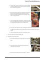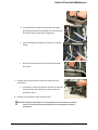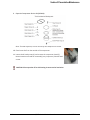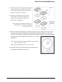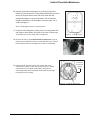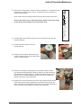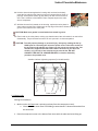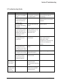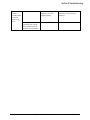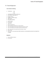
1
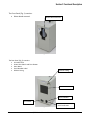
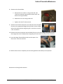
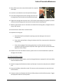
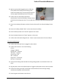
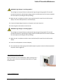
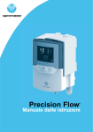
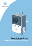
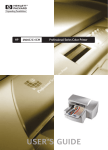
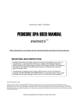
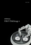
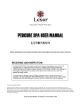
Q50 Compressor Technical Service Manual 3100792 Revision A This document contains proprietary information to Vapotherm Corporation, and its receipt or possession does not convey any rights to reproduce its content, or to manufacture or sell any product described. Reproduction, disclosure, or use other than for the intended purpose without specific written authorization of Vapotherm Corporation is strictly forbidden. This Technical Service Manual is subject to change without notification. Revision/Change Record REVISION A ECO # 15-281 Important Safety Information This manual is subject to periodic review, update and revision. Always obtain and consult the latest revision before undertaking any service of the equipment. Before performing any service on the Q50 Compressor read and review this entire manual. After performing any service or repair always perform the operational checkout in Section 8 of this manual. All tests must pass before unit can be put back in service. Always disconnect the electrical power before performing service or maintenance procedures detailed in this manual. Genuine replacement parts manufactured or sold by Vapotherm must be used for all repairs. Technical Competence The procedures described in this service manual should only be performed by competent individuals who have a general knowledge of and experience with devices of this nature. No repairs should ever be undertaken or attempted by anyone not having such qualifications. Use a static strap and/or a static control work station to ensure that static charges are safely conducted to ground and not through static sensitive devices. Whenever this Electrostatic Discharge (ESD) symbol appears beside a procedure, follow appropriate static control precautions. i Q50 Technical Service Manual 3100792 Rev A Limited Warranty Vapotherm expressly warrants, for a period of one (1) year from the date of shipment by Vapotherm to the initial purchaser of the Q50 device (“Customer”) that the Q50 device shall meet the specifications set forth in the applicable official operating instructions for use provided with each Q50 device (the “Instructions”). The sole remedy for this warranty is that Vapotherm shall, at its sole option, either refund, repair or replace any part or all of any Q50 device that is defective at no cost to the Customer. Vapotherm shall pay any shipping charges required in repairing or replacing any part or all of a Q50 device provided that such Q50 device is shipped back to Vapotherm within three (3) months of the date the Q50 device was originally shipped to the Customer. Thereafter, shipping charges shall be paid by the Customer. Customer shall also be responsible for the cost of labor for repairs. The warranty set forth herein shall become null and void if: (1) the Q50 device is not used or serviced in accordance with the applicable Instructions or any related preventative maintenance instructions provided with the Q50 device; or (2) repairs or service are performed or attempted on the Q50 device by anyone other than Vapotherm or a Vapotherm-certified service center. EXCEPT AS EXPRESSLY SET FORTH ABOVE, VAPOTHERM MAKES NO WARRANTY, EXPRESS, IMPLIED, STATUTORY OR OTHERWISE, WITH RESPECT TO THE PRODUCTS OR ANY OTHER ITEMS PROVIDED BY VAPOTHERM OR OTHERWISE IN CONNECTION WITH THIS AGREEMENT, AND HEREBY EXPRESSLY DISCLAIMS ANY OTHER FORM OF WARRANTY, INCLUDING, WITHOUT LIMITATION, ANY WARRANTY OF MERCHANTABILITY OR FITNESS FOR A PARTICULAR PURPOSE. THIS STATED WARRANTY IS EXCLUSIVE AND IN LIEU OF ALL OTHER WARRANTIES PROVIDED BY LAW. ii Q50 Technical Service Manual 3100792 Rev A TABLE OF CONTENTS Important Safety Information ................................................................................................................................. i Technical Competence ........................................................................................................................................... i Limited Warranty ................................................................................................................................................... ii 1. Introduction ................................................................................................................................................... 1-1 2. Principles of Operation ................................................................................................................................. 1-1 3. Functional Description .................................................................................................................................. 1-1 4. Specifications ................................................................................................................................................ 4-1 4.1 Main Specifications ................................................................................................................................. 4-2 4.2 Performance ........................................................................................................................................... 4-3 4.3 Environmental Requirements ................................................................................................................. 4-4 4.4 Life Expectancy of Compressor .............................................................................................................. 4-5 5. Preventative Maintenance ............................................................................................................................ 5-1 5.1 4000 Hour PM Procedure ....................................................................................................................... 5-1 5.1.1 Replace the Air Intake Muffler (IFU refers this as Suction filter) .................................................... 5-1 5.1.2 Replace the filter in the Auto-draining Air Filter .............................................................................. 5-2 5.2 8000 Hour PM Procedure ....................................................................................................................... 5-3 5.2.1 Servicing the Compressor Motor .................................................................................................... 5-4 5.2.2 Reassembly .................................................................................................................................. 5-15 5.2.3 Electrical Analyzer Testing ........................................................................................................... 5-15 5.2.4 Hi Pot Safety Testing .................................................................................................................... 5-15 5.2.5 Replacing the Air Intake Filter....................................................................................................... 5-15 5.2.6 Fuse Replacement ........................................................................................................................ 5-17 6. Ordering PM parts....................................................................................................................................... 5-18 7. Cleaning and disinfection .............................................................................................................................. 7-1 7.1 Exterior .................................................................................................................................................... 7-1 7.2 Air Inlet Filter ........................................................................................................................................... 7-1 8. Troubleshooting Guide ................................................................................................................................. 8-1 9. Operational Checklist .................................................................................................................................... 9-1 9. Tools and Equipment .................................................................................................................................. 10-1 For further information contact: Vapotherm Inc. 22 Industrial Drive Exeter, NH 03833 USA Phone: 603-658-0011 Fax: 603-658-0181 www.vtherm.com May be patented www.vtherm.com/patents iii Q50 Technical Service Manual 3100792 Rev A Section 1 Introduction 1. Introduction The Vapotherm Q50 air compressor supplies air up to 35L/min. in order to support use of the Vapotherm Precision Flow system in the absence of wall or tank supplied air. The compressor was designed to be mounted on a Precision Flow Roll Stand, or placed directly on a flat level floor. The low profile footprint, light weight, and pole mounting capability allow for multiple use configurations and modes of transport. The Vapotherm Q50 Air Compressor is designed for use only with the Vapotherm Precision Flow system. The compressor is intended to supplement the air needs of the Precision Flow in the event that wall or tank air is not available. It is for institutional use only. It is not intended for home use. GENERAL WARNING: Federal law (US) restricts the sales of this device to, or on the order of, any physician. This device should be used ONLY by a trained operator. For more information, see the Precision Flow Operating Instruction Manual. 2. Principles of Operation The air compressor starts after being plugged in and power inlet switch toggled. The power inlet switch is located above the power inlet on the unit. Ambient room air is pulled in through the air intake filter on the unit, past the heat exchange coil and into the compressor. (Note: Excess moisture is directed to the water bottle reservoir.) Here it is compressed, moves through the heat exchange coil, in order to reduce the air temperature, through an auto draining air filter, pressure relief valve, and pressure regulator. The air then exits the unit and is delivered to the Precision Flow via the air hose. 3. Functional Description The air compressor is comprised of the following components: Air Intake Filter Compressor Heat Exchange Coil Auto-drain Air Filter Air Intake Muffler Pressure Regulator Pressure Relief Valve Tubing/Piping Sound Deadening Foam Housing Top/Bottom 1-1 Q50 Technical Service Manual 3100792 Rev A Section 3 Functional Description The Front Panel (Fig. 1) contains: Water bottle reservoir Water Bottle Reservoir Figure 1 The Rear Panel (Fig. 2) contains: Air Intake Filter Power Inlet Switch and Fuse Drawer Hour Meter Serial Number Label DISS Air Fitting DISS Air FItting Air Intake Filter Serial Number Label Hour Meter Figure 2 3-1 Q50 Technical Service Manual Power Inlet Switch and Fuse Drawer 3100792 Rev A Section 3 Functional Description Power Inlet Switch The Vapotherm Q50 compressor makes use of a medical grade power inlet switch. The power inlet switch contains two (2) fuses. 5ET 8-R (5mm X 20mm, 8A, SLOW BLOW, GLASS FUSE, 250V) WARNING: To avoid risk of electric shock, this equipment must only be connected to supply mains with protective earth. Air Intake The compressor utilizes air from its surrounding environment. It passes through multiple stages of filtration prior to delivery to the Precision Flow. The first filtration stage is accessible from the outside and should be cleaned one per week according to maintenance procedures below. WARNING: Never restrict or block the air intake. This could result in failure to deliver therapy as intended. Air Outlet The air exiting the Q50 compressor is to be used only in conjunction with the Vapotherm Precision Flow system. The compressor output is designed to match the performance needs of the Precision Flow and as such has no user adjustable settings or gauges. WARNING: The Q50 Compressor is only to be used with the Vapotherm Precision Flow system. 3-2 Q50 Technical Service Manual 3100792 Rev A Section 4 Specifications 4. Specifications 4.1 Main Specifications Power Supply: 115V~ ±10%, 60Hz Continuous Flow: 0-35 Input Power: <600VA 4.2 Performance No. Item Description 1 Output Pressure The output pressure is 35-40 psi. 2 Flow 0-35 L/min. 3 Safety Pressure of Air Path Air Tightness The compressor will recirculate pressures in excess 75 psi through a feedback loop The compressor shall not bleed any quantity of air that would otherwise impact full therapy at 35 L/min A pressure of 35 psi will be reached within 30 seconds of the compressor being turned on The noise level is 54 dBA on average* 4 5 6 Pressure Rise Time Noise 7 Electrical Safety Electrical Safety: Meets requirements as defined by IEC 60601-1 “medical electrical equipment, Part 1 general safety requirement”. *Results obtained as follows: The average sound level measure 1m from the front of the unit, at height of 1m in an anechoic chamber is 54 dB(A). 4.3 Environmental Requirements Operation: Temperature +18°-+30°C Relative Humidity 10-90% Storage: -10°-+50°C 20-90% CAUTION: If the storage conditions are outside of the stated operating range, the Q50 Compressor must be acclimated to the operating environment for a minimum of 8 hours prior to use. 4-1 Q50 Technical Service Manual 3100792 Rev A Section 4 Specifications 4.4 Life Expectancy of Compressor The average life expectancy will be 20,000 hours, based upon operating conditions and with maintenance being performed as outlined on page 5-1. Dimensions and Weight Dimensions: Weight: 4-2 20.5in(L)X19in(H)X9in(W) 44lbs Q50 Technical Service Manual 3100792 Rev A Section 5 Preventative Maintenance 5. Preventative Maintenance 5.1 4000 Hour PM Procedure The 4000 hours preventive maintenance procedure includes the following: Replacing the air intake muffler Replacing the filter in the auto-draining air filter Replacing the air intake filter Note: Before you begin, read these instructions thoroughly and assemble the necessary tools. Tools required: 1/8 Allen wrench 3/16 Allen wrench - to remove the pole clamp if needed (a manual set of Allen wrenches is recommended to prevent the threads from stripping) WARNING: Unplug the compressor before beginning disassembly. 1. Remove 18 screws from the housing top with 1/8 Allen wrench (9 per side) If you are unable to access the screw under the pole mount, remove the pole mount with a 3/16 Allen wrench first. 2. Remove the housing top. 5.1.1 Replace the Air Intake Muffler 3. Locate the Air Intake Muffler on the intake side of the compressor. 4. Grasp the tubing near the Air Intake Muffler and the Air Intake Muffler and pull the tubing away from the foam insert (Tubing Constraints). 5-1 Q50 Technical Service Manual 3100792 Rev A Section 5 Preventative Maintenance 5. Remove the Air Intake Muffler from the tubing. 6. Replace with a new Air Intake Muffler. 7. Reseat the tubing in the tubing constraints. 5.1.2 Replace the filter in the Auto-draining Air Filter Clear tubes (to disconnect) Auto-draining Air Filter 8. Disconnect the blue water-drain tubing (push in on the connector to release the tubing). 9. Disconnect the clear tubes (push in on the connector to release the tubing) on either side of the Auto-draining Air Filter. 10. Grasp the Auto-draining Air Filter by the bowl and pull away from the constraints. Water drain tube 11. Unscrew the polycarbonate bowl (1/4 turn to the left). Note the lock and unlock markings on the bowl. 12. Slide the bowl off the filter assembly. 13. Unscrew the white plastic wheel and remove the filter from the assembly. 14. Replace the white filter ensuring the larger diameter end is inserted on to the post first (filter will not seat firmly if the smaller diameter end is installed first). 15. Screw on the white plastic wheel on to the filter assembly. 5-2 Q50 Technical Service Manual 3100792 Rev A Section 5 Preventative Maintenance 16. Reattach the polycarbonate bowl to the assembly. 17. Reattach the tubing coming from the Relief Valve to the filter assembly. 18. Reseat the filter assembly into the foam constraints. 19. Reattach the remaining tubing. Ensure all tubing is firmly connected to prevent air leakage and potential loss of air pressure. Filter 20. Replace the housing top. a. Extend the black foam side while replacing to prevent damage to the internal components. b. Ensure the insulated foam is facing the exhaust side of the compressor (the side with no components). c. Ensure the top edges of the housing extend over the front and back ends of the compressor base (this will prevent water ingress to the unit and also facilitate alignment of the screws). 21. Reattach the screws with Allen wrenches. (Power driver not recommended due to potential damage to the threads). 22. Connect the compressor to a PF unit and run the PF unit at 35 at 21% FiO2 for 5 minutes to confirm the is functional and able to maintain flow. 5.1.3 Replace the Air Intake Filter 23. Locate the Air Intake Filter on the back of the compressor and remove from the compressor. 24. Place a new filter in the inlet opening making sure that the filter is completely tuced into the opening and that there are no gaps around the filter. 5-3 Q50 Technical Service Manual 3100792 Rev A Section 5 Preventative Maintenance 5.2 8000 Hour PM Procedure The 8000 hours preventive maintenance procedure includes the following: Servicing the Compressor Motor Replacing the filters This procedure is recommended every 8000 hours of compressor operation. Note: Before you begin, read these instructions thoroughly and assemble the necessary tools. Tools Required: 7/8” wrench Flat head screwdriver 11/32” socket ¼” nut driver Teflon tape Spline insertion tool 1/4” Hex Socket attachment for torque wrench Torx T-20 attachment for torque wrench (for retainer screws) Torx T-25 attachment for torque wrench (for head screws) 5/32” Hex wrench for torque wrench (eccentric screw) Clean Cloths Electrical Safety Analyzer Hi-Pot tester Allen wrench set (a manual set of Allen wrenches is recommended to prevent the threads from stripping) WARNING: Unplug the compressor before beginning disassembly. 5.2.1 Servicing the Compressor Motor 1. Remove 18 screws from the housing top with 1/8 Allen wrench (9 per side) If unable to access the screw under the pole mount, remove the pole mount with a 3/16 Allen wrench first. Save these screws. 2. Remove the housing top. 5-4 Q50 Technical Service Manual 3100792 Rev A Section 5 Preventative Maintenance 3. Remove the through-wall connector (bulkhead fitting) from the air outlet port. a. Loosen and then completely removing the nut on the inside of the housing by the regulator using two 7/8” wrenches (one on the inside of the housing and one to hold the nut on the exterior) b. Slide the nut and washer off the fitting and onto the exposed metal pipe c. Loosen and remove the through-wall connector by unscrewing the exterior nut (This will disconnect the exposed metal pipe from either the regulator side or the through-wall connector side.) 4. Remove the compressor from the base housing. a. Lay the compressor on its side, with the components facing up. Place foam or other equivalent supports to elevate the housing bottom from the bench. b. Using a flathead screwdriver, pry out the two Wago Terminal Blocks from the foam insert (one is underneath the other). c. Carefully pull the base housing away from the compressor insert until there is approximately a 2-3” gap. 5-5 Q50 Technical Service Manual 3100792 Rev A Section 5 Preventative Maintenance d. Using an 11/32” socket, remove the top nut and star washer from the ground post to disconnect the compressor ground wire from the housing bottom. e. Disconnect the brown wire (from compressor) and the black wire with white shrink wrap (from fan) from one of the Wago Terminal Blocks by lifting the corresponding orange tabs to an upright position. f. From the second Wago Terminal Block - disconnect the blue wire (from compressor) and the black wire (from fan) by lifting the corresponding orange tabs to an upright position. g. At this point, the compressor insert is no longer connected to the housing bottom and the Wago Terminal Blocks should still have two connections each (power inlet and hour meter). h. Slide the housing bottom away from the compressor insert. 5. Set the Air Intake Filter and water bottle aside. 6. Disconnect the hose connections. a. Disconnect the tubing from the right side of the Auto-Drain Filter. b. Disconnect the other end of this same tubing from the outlet side of the cooling coil. c. Disconnect the braided hose from the barbed “T” junction. 5-6 Q50 Technical Service Manual 3100792 Rev A Section 5 Preventative Maintenance d. Using a flathead screwdriver disconnect the straight gray fitting attached to the braided hose from the push to connect fitting on the heat exchange coil. e. Pull the straight gray fitting from the push to connect fitting. f. Disconnect the blue water-drain hose from the AutoDrain filter. 7. Carefully lift the top half of the foam insert away from the compressor. a. If necessary, remove the capacitor and the fan from the top foam insert and place them in their locations on the bottom insert. 8. Remove the compressor motor from the insert. CAUTION: Improper assembly or use of damaged parts may lead to premature failure. To avoid frequent repairs follow the recommended assembly procedures. 5-7 Q50 Technical Service Manual 3100792 Rev A Section 5 Preventative Maintenance 9. Open the Compressor Service Kit (SK2668). Note: To avoid confusion, service one end of the compressor at a time. 10. Clean loose dirt from the outside of the compressor. 11. Loosen the 8 head screws (1) and remove the compressor head (2). Note orientation of head for reassembly (very important). Discard head screws. CAUTION: Place capacitor off to side leaving it connected to lead wires. 5-8 Q50 Technical Service Manual 3100792 Rev A Section 5 Preventative Maintenance 12. Carefully remove the valve plates (4) from the bottom of the head, or cylinder sleeves. Note orientation with respect to the tab on valve plate for reassembly. See Figure 1. 13. Remove the head gasket O-rings (3) and discard them. Turn the valve plates over. Remove the valve plate O-rings (5) and discard them. See Figure 2. Note: Number 4 Valve plate orientation is a representation, note which valve flapper orientation you have. 14. Remove the intake valve flapper (1), restraint (2), keeper (3) if assembled, and screw from the bottom of the valve plate and discard. Clean the bottom of the plate with a clean, soft cloth. Install the new intake valve flapper, and restraint (if one was removed). The valve keeper should be placed on top of the flapper so that the word “UP” is visible. See Figure 2. 1 3 2 Note: Pay close attention to valve assembly. Some parts in kit may not be for your model. Note: Torque new flapper screw to 18 inch- pounds. 15. Install the new O-ring, seating it firmly into the groove with your finger or blunt object. See Figure 2. Figure 2 5-9 Q50 Technical Service Manual O-Ring Groove 3100792 Rev A Section 5 Preventative Maintenance 16. Remove the exhaust valve flapper (1), restraint (2) and valve keeper (3) from the top of the valve plate and discard them. Clean the top of the plate with a clean, soft cloth. Install the new exhaust valve flapper, restraint and keeper. The valve keeper should be placed on top of the flapper so that the word “UP” is visible. See Figure 3. 1 2 3 Note: Torque flapper screw to 18 Inch-pounds. 17. Install the new head gasket, seating it firmly into the groove with your finger or blunt object. See Figure 3. Set aside. Repeat steps 13 through 16 to service other end of compressor. Figure 3 O-Ring Groove 18. Remove the fan by using two flat blade screwdrivers to pry off, making sure screwdriver contact is made with hub back, and not the fan blades. Note fan orientation and color for reassembly. Eccentric Set Screw Access Hole 19. Insert the 5/32” Hex wrench into the access hole in the compressor housing. Loosen the set screw 1/4 turn. Rotate connecting rod to top dead center (180°) and slide the connecting rod/eccentric assembly off the shaft and through the opening in the housing. Figure 5 5-10 Q50 Technical Service Manual Eccentric Set Screw 3100792 Rev A Section 5 Preventative Maintenance 20. Secure the rod assembly in a fixture. Remove the sleeve (1 - Discard) from the connecting rod. Remove the screw (2 - Discard) from the cup retainer (3 Retain for reassembly). Note: Read before proceeding with the following disassembly instructions: Remove the piston cup (4 - Discard) and wipe debris from the top of the connecting rod and retainer with a clean damp cloth. 1 2 3 4 21. Carefully place new cylinder sleeve (1) over connecting rod top with the machine rabbit up. 22. Carefully pull the cylinder sleeve up forming the cup. 23. Rotate the rotor shaft so that flat faces up (12:00). Position piston cup at bottom dead center of cylinder sleeve. 24. Slide the connecting rod assembly onto the shaft until the eccentric face positively stops against the bearing. Align the eccentric setscrew with the flat of the shaft. Rotate the eccentric and shaft 90 degrees so the set screw is visible through the access hole in the housing, and tighten set screw to 125 Inch-pounds. 25. Align the flat on the fan with the flat on the motor shaft and slide the fan back onto the motor shaft, making sure you position the fan clip in the same orientation as it was before you removed it. Incorrect orientation of the fan will not provide adequate cooling of the compressor. 5-11 Q50 Technical Service Manual 3100792 Rev A Section 5 Preventative Maintenance 26. Hold the sleeve down against the housing with one hand, and slowly rotate the fan with the other hand to ensure all components are lined up properly. As the piston travels up and down it will also rock from side to side. This is a feature of the WOB-L Piston. Repeat steps on the other side of compressor. 27. With the sleeves firmly seated on the housing, replace the valve plates in same manner as they were. Make sure the top edge of the sleeve locates in the O-ring groove in the bottom of the valve plate. CAUTION: Make sure gasket is not twisted when seated in groove. 28. Place head on the valve plates, making sure that the same letter orientation is as was before disassembly. Torque the head screws to 55 Inch- pounds in a crisscross pattern. CAUTION: To avoid property damage or personal injury, always try rotating the fan by HAND prior to connecting the unit to the power source. Check for suction at the air inlet port by placing your finger over the port as you turn the fan. You should feel a slight suction with each rotation of the fan. If you don’t feel suction, or if you feel or hear a thump as you turn the fan, DO NOT CONNECT THE UNIT TO A POWER SOURCE; review the assembly procedure for possible error. Numbers indicate tightening sequence for Head Assembly. 5.2.2 Reassembly 4 6 2 5 3 7 8 1 Power Leads Cooling Fan Installation 1. Make sure the Air Flow arrow is pointing up (away from the compressor motor). a. *Reconnect blue water-drain hose leading to water bottle if it becomes detached from the connectors 2. Place the compressor motor in the bottom foam insert with the tubes and wires facing up. 5-12 Q50 Technical Service Manual 3100792 Rev A Section 5 Preventative Maintenance 3. Ensure the wires are inserted into the wire channels of the foam insert using a spline insertion tool or similar blunt tool. 4. Replace the top foam insert while feeding the three hoses up through their appropriate openings. a. Ensure the capacitor is aligned with the capacitor opening and the fan is aligned with the fan slot. b. Ensure the elbow and tubing for the water drain are also in their channels. c. Pull the blue water drain tube through the foam insert opening where the heat exchange coil is visible. d. The two sides should now fit together with minimal gap. 5. Reconnect hoses. a. Connect the blue water-drain hose to the Auto-Drain Filter. b. Reinsert the straight gray fitting into the push to connect fitting on the cooling coil. Pull gently on the braided tube to ensure a good connection. c. Reconnect the other end of the 3/8” rigid tubing to the Auto-Drain filter and pull gently to ensure a good connection. d. Insert the 3/8” tubing into the foam tubing constraints. e. Insert the barbed “T” into the 3/8” braided tube at the compressor inlet. Replacing the Housing Bottom 6. Gather the compressor and fan wires and tuck them into the Wago terminal block space on the foam insert to prevent from damaging them while sliding the housing back on. 7. While the foam insert is elevated on the supports, carefully slide the housing bottom back onto the foam insert. 5-13 Q50 Technical Service Manual 3100792 Rev A Section 5 Preventative Maintenance 8. Reconnect the Ground Wire. a. Reinstall the star washer on the ground stud, then install the compressor ground wire and the other star washer on the ground stud. b. Reattach the nut onto the ground stud. c. Tighten with 11/32” socket wrench. 9. Reconnect the brown compressor wire and white shrink wrapped fan wire to the appropriate Wago Terminal Block. Set the orange tabs to the closed position and gently pull on the wires to ensure a firm connection. 10. Reconnect the blue compressor wire and black fan wire to the other Wago Terminal Block. Set the orange tabs to the closed position and gently pull on the wires to ensure a firm connection. 11. Insert the Wago Terminal Blocks back into the space in the foam insert –one over the other. 12. Slide the foam inserts completely into the housing bottom and stand up the compressor. Reconnect the through-wall connector 5-14 Q50 Technical Service Manual 3100792 Rev A Section 5 Preventative Maintenance 13. Wrap Teflon tape twice around the threads of the exposed metal pipe. 14. Install the nut and washer onto the exposed metal pipe. 15. Insert the through-wall connector through the hole in the housing bottom and thread onto the exposed metal pipe. 16. Tighten the through-wall connector with a 7/8” wrench while holding the regulator to prevent rotation until the through-wall connector has contact with the housing base. 17. Slide the tooth washer over the threads on the inside of the housing base, and tighten the nut using a 7/8” wrench. 18. Reinstall the Air Intake Filter and water bottle. 19. Replace the housing top. a. Extend the black foam side while replacing to prevent damage to the internal components b. Ensure the insulated foam is facing the exhaust side of the compressor (the side with no components) c. Ensure the top edges of the housing extend over the front and back ends of the compressor housing base (this will prevent water ingress to the unit and also facilitate alignment of the screws). 20. Reattach the screws with Allen wrenches. (power driver not recommended due to potential damage to the threads) 5.2.3 Electrical Analyzer Testing 21. On your electrical safety analyzer, press the Omega (Ω) button to prepare for the Ground Wire Resistance Measurement. 22. Attach the plug end of the Red test lead to (V/ Ώ/A) jack. Connect the red probe to the “Ø/Null” jack. 23. Press the F4 softkey, labeled Zero Leads. This zeroes out the measurement to cancel the test lead resistance. 24. Connect a power cord between the Electrical Safety Analyzer and the Q50 compressor. Toggle the Q50 power switch to the On position. 5-15 Q50 Technical Service Manual 3100792 Rev A Section 5 Preventative Maintenance 25. With the test lead still plugged into the V/ Ώ/A jack, firmly hold the test lead tip to the housing screw closest to the power inlet. To ensure proper electrical contact, apply considerable pressure to the probe. 26. Confirm that the “Ground Wire Resistance” measurement is less than 0.20 Ohms. Remove the red probe from the housing top screw. This concludes the “Ground Cord Resistance Measurement” test. 27. Press the microAmp (μA) button to select the units to be used for the Ground Leakage Current test. 28. Press the F1 softkey labeled “Earth” on the screen above the softkey. 29. Press the Polarity button until “Normal” appears on the screen. 30. Press the Neutral button until “Open” appears on the screen. 31. Confirm that the Ground Leakage Current - Normal - Open measurement is less than 500 μA . 5.2.4 Hi Pot Safety Testing 32. Confirm that the Hi-Pot Tester is plugged in and turned on. 33. Confirm that the tester is set to the following: AC test Voltage = 1.800 kV High Current = 10.00 mA Test Time = 5 seconds Low Current = OFF ARC = 10.00 mA Ramp Time = 5.0 seconds Fall Time = 5.0 seconds 34. Verify that the black ground lead and the red high voltage probe are connected to the Hi- Pot tester. 35. Plug the power cord into the Q50 compressor. Toggle the Q50 power switch to the On position. 36. Connect the Hi-Pot ground wire to the power cord Ground and connect the high voltage connector to the power cord line terminal. 37. Press the green start button to start the test. 5-16 Q50 Technical Service Manual 3100792 Rev A Section 5 Preventative Maintenance WARNING: High Voltage is now being applied. The red light on the tester flashes to indicate that high voltage is being applied. The test will proceed automatically. Hold the high voltage probe in the LINE socket until the tester completes the test sequence (the red light will stop flashing). 38. When the test is complete record the current and the Pass/Fail status from the Hi-Pot tester display. Press the red Stop button to reset the display. 39. Connect the high voltage connector to the power cord neutral terminal. 40. Press the green start button to start the test. WARNING: High Voltage is now being applied. The red light on the tester flashes to indicate that high voltage is being applied. The test will proceed automatically. Hold the high voltage probe in the LINE socket until the tester completes the test sequence (the red light will stop flashing). 41. When the test is complete record the current and the Pass/Fail status from the Hi-Pot tester display. 42. Press the red Stop button to reset the display. 43. This concludes the Hi-Pot testing and the Q50 compressor power cord can be disconnected and the power switch toggled off. 5.2.5 Replacing the Air Intake Filter The air intake filter can be removed easily. When replacing with a new filter, ensure all corners are tucked in and there are no gaps around the filter. 5.2.6 Fuse Replacement 5-17 Q50 Technical Service Manual 3100792 Rev A Section 5 Preventative Maintenance Fuses need to be replaced only when blown. The mains fuses : 5ET 8-R (5mm X 20mm, 8A, SLOW BLOW, GLASS FUSE, 250V) are located next to the power cord inlet. Use two small flat blade screwdrivers to push the release clips on either end of the fuse block toward each other and release the fuse block to access the fuses. 6. Ordering PM parts Parts are availiable by contacting Vapotherm Total Customer Care. Phone: 603-658-4899 Email: [email protected] 5-18 Q50 Technical Service Manual 3100792 Rev A Section 7 Cleaning and Disinfection 7. Cleaning and disinfection 7.1 Exterior and Water Bottle 1. Use a warm water and soap solution to wipe the exterior if needed. Use clean, warm water to remove residual residue. Do not allow liquids to infiltrate beyond the exterior surfaces of the compressor or into any electrical interfaces or components. 2. Rince the water bottle reservoir with warm soapy water after emptying the water bottle reservoir, and between patient uses. Confirm rinsing of the water bottle reservoir to remove soap residue. 3. Disinfect according to institution policy only with chemicals that do not contain or produce volatile organic compounds (VOCs) and are non-corrosive. The following agents were tested and confirmed to have no adverse effects on the compressor: Solution of 6% Chlorine Solution of 15% hydrogen peroxide Solution of 90% isopropyl alcohol Water Dry Kim Wipes SaniCloth AF3 Germicidal Wipes Cavi Wipes 7.2 Air Intake Filter 4. The air intake filter in the back of the unit should be removed weekly and cleaned. 5. Brush gross dust particles off the surface of the filter. 6. Submerge filter in warm, soapy water and gently squeeze and massage the filter to flush any dust particles from the interior. 7. Air dry. 8. Replace the filter, making sure that it is completely tucked into the opening and there are no gaps around the filter. This procedure will help to assure the product’s performance and service life by allowing the maximum amount of clean, dust-free air to be available for cooling the compressor motor. 7-1 Q50 Technical Service Manual 3100792 Rev A Section 8 Operational Checklist Check ( √ ) if complete & performance is acceptable VAPOTHERM Q50 COMPRESSOR Pre-Use Operational Checklist Unit Serial #: Initials: Date: If performing the pre-operational checkout with access to a Precision Flow unit and Disposable Patient Circuit: 1.1 Affix a Precision Flow unit to an IV pole or test rack. Install a High Flow Disposable Patient Circuit (DPC) in the Precision Flow. See the Precision Flow Instructions for Use Manual: Section 7.5 for additional information. 1.2 Attach a sterile water bag to the spiked tube of the DPC and unclamp the spike tube clamp to allow the DPC to fill with water. The Water Out Icon may blink until the DPC has completely filled with water. 1.3 Ensure that the air inlet gas filter assembly, with hose attached, is installed in the air inlet port on the rear of the Precision Flow unit. 1.4 Connect the other end of the air hose to the DISS air fitting on the back of the Q50 compressor. 1.5 Connect Q50 power cord to the rear of the Q50 compressor. 1.6 Connect the other end of the power cord to AC power. 1.7 Turn on the Q50 compressor by toggling the power inlet switch above the power cable on the back of the Q50. 1.8 Set the Precision Flow unit to: 21% FiO2, 33°C and 35 LPM SeeStart the Precision Flow Operating Instrctions Sectionfor 8 "Adjustments" for additional information. 1.9 the Precision Flow unit, waitManual: 30 seconds the flow to stabilize. 1.10 Verify that the Gas Supply Absent icon (gas tank) does not illuminate while the Precision Flow unit runs for 2 minutes. 1.11 Put the Precision Flow unit into Standby mode. 1.12 Turn off the Q50 compressor by toggling the power inlet switch above the power cable on the back of the Q50. 1.13 Disconnect the air hose from the DISS fitting on the back of the Q50 compressor. Be aware that compressed air may be released during the hose disconnection and removal. 1.14 Disconnect the power cord from AC power. 1.15 Disconnect the power cord from the rear of the Q50 compressor. If performing the pre-operational checklist without access to a Precision Flow: 2.1 Connect the power cord to the rear of the Q50 compressor. 2.2 Connect the other end of the power cord to AC power. 2.3 Turn on the Q50 compressor by toggling the power inlet switch above the power cable on the back of the Q50. 8-1 Q50 Technical Service Manual 3100792 Rev A Section 8 Operational Checklist 2.4 Verify that compressed air is output from the DISS fitting on the back of the Q50 compressor. 2.5 Turn off the Q50 compressor by toggling the power inlet switch above the power cable on the back of the Q50. 2.6 Disconnect the power cord from AC power. 2.7 Disconnect the power cord from the rear of the Q50 compressor. 8-2 Q50 Technical Service Manual 3100792 Rev A Section 9 Troubleshooting 9.Troubleshooting Guide Trouble No air output Fault State Power inlet switch is on but there is no audible noise Power cord is connected to a functioning power outlet but there is no audible noise The fuse failed repeatedly after being replaced Power cord is connected to a functioning power outlet and there is an audible click inside the compressor, but no other noise The cooling fan is running but not the compressor Possible Cause Power cord is not connected or connected to a faulty outlet The fuse is blown Method Connect power cord and ensure that the outlet is functioning Replace fuse with 250V 8A slow-blow fuse, Part number: 3100727 The soft start valve has failed Call for service The cooling fan has failed, possibly causing the compressor to overheat or fail Call for service Compressor has overheated The cooling fan is running but not the compressor even when the compressor is cool The compressor and cooling fan are running The compressor has failed Ensure that the air intake filter is clean and not obstructed. Allow compressor to cool for 20-30 minutes and attempt to restart Call for service The air pipeline is not tightened properly Tighten the fittings The air pipeline hose is OK and the exhaust noise can be heard inside the machine Pipeline inside has disconnected. Call for service Air output is low causing PF to alarm Insufficient pressure Internal pressure regulator below recommended operating levels Call for service There is condensation in the PF water trap Insufficient pressure Internal pressure gauge below recommended operating levels Call for service 9-1 Q50 Technical Service Manual 3100792 Rev A Section 9 Troubleshooting There is condensation in the PF water trap, cont. 9-2 Airflow is blocked Air inlet or exhaust are blocked or air filter needs cleaning Clean air filter and ensure that the air inlets are not blocked Cooling fan is not operating (no airflow from exhaust port on bottom of compressor) The fan has failed Call for service Q50 Technical Service Manual 3100792 Rev A Section 10 Tools & Equipment 10. Tools & Equipment. Tools include the following: Torx Drivers: T-20 T-15 T-10 Small blade flat head screw driver set Small Philips screw driver set. Diagonal Cutters Socket for encoder (11mm) 7/8” wrench Flat head screwdriver 11/32” socket ¼” nut driver Teflon tape Spline insertion tool 1/4” Hex Socket attachment for torque wrench Torx T-20 attachment for torque wrench (for retainer screws) Torx T-25 attachment for torque wrench (for head screws) 5/32” Hex wrench for torque wrench (eccentric screw) Clean Cloths Allen wrench set (a manual set of Allen wrenches is recommended to prevent the threads from stripping) Equipment 10-1 Electrical Safety Analyzer Hi-Pot tester Q50 Technical Service Manual 3100792 Rev A For Questions and Further Assistance Please Contact Vapotherm Technical Support Phone: 1.855.557.8276 Email: [email protected] Q50 Technical Service Manual 3100792 Rev A