1
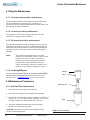
Precision Flow® Technical Service Manual 3004005 Revision K This document contains proprietary information to Vapotherm Corporation, and its receipt or possession does not convey any rights to reproduce its content, or to manufacture or sell any product described. Reproduction, disclosure, or use other than for the intended purpose without specific written authorization of Vapotherm Corporation is strictly forbidden. This Technical Service Manual is subject to change without notification. Revision/Change Record REVISION E ECO # 12-015 F 12-031 G 14-030 H 14-104 I 15-148 J 15-232 K 15-157 Important Safety Information This manual is subject to periodic review, update and revision. Always obtain and consult the latest revision before undertaking any service of the equipment. Before performing any service on the Precision Flow® read and review this entire manual. After performing any service or repair always perform the pre-use checkout in section 5 of this manual. All tests must pass before unit can be put back in service. Always disconnect the electrical power and gas supplies before performing service or maintenance procedures detailed in this manual. Reconnect only if you are specifically instructed to do so as part of the procedure. Genuine replacement parts manufactured or sold by Vapotherm must be used for all repairs. Technical Competence The procedures described in this service manual should only be performed by competent individuals who have a general knowledge of and experience with devices of this nature. No repairs should ever be undertaken or attempted by anyone not having such qualifications. Use a static strap and/or a static control work station to ensure that static charges are safely conducted to ground and not through static sensitive devices. Whenever this Electrostatic Discharge (ESD) symbol appears beside a procedure, follow appropriate static control precautions. LIMITED WARRANTY Vapotherm, Inc. warrants that the Precision Flow® shall be free of defects of workmanship and materials and will perform in accordance with the product specifications for a period of 1 year from the date of sale by Vapotherm, Inc. If the product fails to perform in accordance with the product specifications, Vapotherm, Inc. will repair, or replace, at its option, the defective material or part. This warranty does not cover damage caused by accident, misuse, abuse, alteration and other defects not related to material or workmanship. VAPOTHERM, INC. DISCLAIMS ALL LIABILITY FOR ECONOMIC LOSS, LOSS OF PROFITS, OVERHEAD OR CONSEQUENTIAL DAMAGES WHICH MAY BE CLAIMED TO ARISE FROM ANY SALE OR USE OF THIS PRODUCT. THIS WARRANTY IS GIVEN IN LIEU OF ALL OTHER EXPRESS WARRANTIES. Copyright © 2012 Vapotherm Corporation All rights reserved. Printed in the U.S.A TABLE OF CONTENTS Section 1 General Information 1.1 Introduction ............................................................................................................................................. 1-1 1.2 Principles of Operation ............................................................................................................................ 1-1 1.3 Functional Description ............................................................................................................................. 1-2 1.4 Specifications ........................................................................................................................................... 1-5 Section 2 Troubleshooting 2.1 Alarms ...................................................................................................................................................... 2-1 Section 3 Corrective Maintenance 3.1 Removing the front cover ........................................................................................................................ 3-1 3.2 Removing the back cover ......................................................................................................................... 3-2 3.3 Removing the side cover .......................................................................................................................... 3-2 3.4 Replacing the batteries or power supply assembly ................................................................................. 3-2 3.5 Replacing the hinged door........................................................................................................................3-5 3.6 Replacing the fan, fan filter or speaker .................................................................................................... 3-4 3.7 Front panel control repairs ...................................................................................................................... 3-4 Section 4 Preventative Maintenance 4.1 Regular Maintenance ............................................................................................................................... 4-1 4.1.1 Semi-annual preventive maintenance ....................................................................................................... 4-1 4.1.2 Annual preventive maintenance ................................................................................................................. 4-1 4.1.3 Bi-annual preventive maintenance ............................................................................................................. 4-1 4.1.4 Ordering PM parts ...................................................................................................................................... 4-1 4.2 Maintenance Procedures ......................................................................................................................... 4-1 4.2.1 Inlet Gas Filter Replacement ....................................................................................................................... 4-1 4.2.2 Oxygen Sensor Replacement ...................................................................................................................... 4-2 4.2.3 Fuse Replacement ....................................................................................................................................... 4-3 4.2.4 Cleaning and disinfection ............................................................................................................................. 4-3 Section 5 Pre-Use Checklist 5.1 Precision Flow Pre-Use Checklist ............................................................................................................. 5-1 Section 6 Tools and Equipment 6.1 Tools and Equipment ............................................................................................................................... 6-1 Section 7 Service Parts 7.1Rear panel parts ........................................................................................................................................ 7-1 For further information contact: Vapotherm Inc. 22 Industrial Drive Exeter, NH 03833 USAPhone: 603-658-0011 Fax: 603-658-0181 www.vtherm.com May be patented www.vtherm.com/patents RMS – UK Limited 28 Trinity Road Nailsea, North Somerset, BS48 4NU United Kingdom Phone +44-1275-85-88-91 Fax +44-1275-85-88-91 Section 1 General Information 1.1 Introduction The Vapotherm Precision Flow® is intended to heat and humidify patient respiratory gases from a source of compressed air and oxygen gases. Warm, humidified gas is delivered from the Vapotherm Precision Flow® to the patient via a proprietary tube-set and disposable water path that is attached to a nasal cannula or mask at the patient. The user can set the oxygen percentage, temperature, and flow rate of the delivered gas. The unit is intended to be pole mounted, attached to an overhead sterile bag of water. Heat and humidification are provided through an exchange cartridge that is placed between the disposable water path and the capital side of the unit. This cartridge acts as the interface to transfer heat from the water that is pumped through the exchanger, transferring humidity by molecular passage of water vapor across the cartridge membrane surfaces. The proprietary tube-set and disposable water path insulates and maintains warm water with heat from an internal heater to surround the gas delivery tube and maintain its temperature as the gas makes its way from the Precision Flow® to the patient cannula or mask. This minimizes water condensation. 1.2 Principles of Operation The Precision Flow® unit is designed to blend and meter oxygen and air (helium/ oxygen mixtures on Precision Flow® Heliox units) to set flow rates and oxygen percentages, to warm and humidify that flow, and then deliver it to the patient. The vapor transfer cartridge is designed to receive the unconditioned breathing gas and add warm water vapor to it. Two separate pathways, one for the breathing gas and the other for the water, intersect when fibers of a special membrane material allow water vapor to pass from the outside of the fiber into the gas stream. A second unique feature of the Precision Flow® unit is the heated vapor delivery tube. The delivery tube delivers the humidified and warmed gases from the vapor transfer cartridge to the patient. The heated delivery allows the breathing gas to pass through an inner tube that is surrounded by circulating warm water. This insulates and maintains the inner tube to the same temperature as the gas flowing through it, thereby, keeping the gases at the desired temperature and eliminating condensation. The water circuit begins at the auto feed reservoir where it is pumped into a process controlled heater. The heated water then flows to the outer lumen of the delivery tube. After the heated water has passed through the entire length of the outer jacket of the delivery tube, it returns to unit and is passed through the vapor transfer cartridge. From there, it completes the loop by flowing back to the input side of the pump. Temperature is sensed just downstream of the cartridge. 1- 1 Technical Service Manual 3004005 Rev K Section 1 General Information 1.3 Functional Description The Precision Flow® warms and humidifies a flow of breathing gas for delivery by nasal cannula at flows from 1 to 40 lpm. The unit incorporates an electronic blender and flow sensors that allow the oxygen percentage and total gas flow to be set independently The Precision Flow® consists of two parts: Main unit • The main unit which contains all the electrical and electronic components including the electronic blender and flow controllers, and sensors to monitor the disposable water path. • Flows of oxygen and air or heliox are regulated by proportional solenoid valves in the gas metering manifold. The flows of oxygen and air or heliox are measured by two mass flow sensors in the flow control manifold. Lookup tables stored in the processor convert A-D units to flow in liters per minute. For any setting of flow and oxygen percentage, the operating software calculates the target flows for oxygen and air or heliox. The proportional solenoid valves are then adjusted until the measured flow for each gas equals the target flow. The system continually monitors the flows and makes small adjustments to the solenoid valves as necessary to maintain the target flows. As a check on the mixing and metering system, an oxygen cell continually reads a sample of the mixed gas. Alarms occur if either flow cannot be adjusted to the target flow, if a mass flow sensor is out of range, or if there is a discrepancy between the oxygen setting and the oxygen cell reading. • Firmware running in the main unit uses sensors to monitor gas pressure, water level and water temperature, and air leaks in the water circuit (bubble detector). Alarms are displayed if any parameters are outside the normal range. Other indicators include backup battery charge, and the type of cartridge installed. See Mode Diagram for a description of the firmware states and transitions. • An internal battery backup will maintain the set flow and oxygen blend for at least 15 minutes without AC power. However, the circulating pump and heater will stop. The battery is designed for temporary power loss, and is not intended for transport. Disposable patient circuit • The disposable patient circuit is comprised of the disposable water path, vapor transfer cartridge and delivery tube. Conditions in the circulating water and gas streams are sensed remotely via the interface between the main unit and the disposable water path. • Vapor transfer cartridge. In the cartridge blended gas passes through the lumens of hundreds of parallel hollow fibers made of a specially developed polymer. Warm water circulates around the fibers and diffuses as vapor through the fiber material into the gas stream flowing through each fiber. There is no direct contact between the water and gas streams. The gas stream leaves the cartridge essentially saturated with vapor at the set temperature. Note: Use only approved cartridges from Vapotherm Inc. • Patient delivery tube. The warmed humidified gas passes through the center of a triple-lumen heated delivery tube. The center lumen is surrounded by two outer lumens carrying warmed water to maintain the temperature of the inner lumen. lumen and to minimize rain-out. A proprietary short nasal cannula is connected to the end of the delivery tube and passes the humidified breathing gas to the patient’s nares. 1- 2 Technical Service Manual 3004005 Rev K Section 1 General Information • Disposable water path. The disposable water path houses a water reservoir, pump rotor, connections for the cartridge and delivery tube, and sensor interfaces to the main unit. Water is pumped past a heater plate and circulates through the outer lumens of the delivery tube. Returning water passes through the outer jacket of the vapor transfer cartridge where some water is lost as vapor to the gas stream. There is no direct contact between water and gas flows. The water then returns to the reservoir. Heater power is regulated continuously to maintain the set temperature. Water replaces evaporative losses in the vapor transfer cartridge via a gravity fed sterile water supply. Air is purged to atmosphere from the circulation via an oleo phobic filter membrane. For a description of the software operating modes see Mode Diagram. 1- 3 Technical Service Manual 3004005 Rev K Section 1 General Information Figure 1-3 Software Mode Diagram The previous diagram illustrates the operating modes for the unit. • Immediately on connection to AC power a POST (Power-On Self-Test) is run to verify proper function of subsystems, sensors and actuators in the Precision Flow® • On successfully completing the POST if there is a DWP in place the unit enters STANDBY, unless there is a test failure. The system will indicate FAULT mode in the temperature display. • The Precision Flow® enters RUN mode from STANDBY when the RUN/ STANDBY button is pressed. Normal operation starts. The pump, heater and gas flow proportioning systems start. Flow, temperature and oxygen % can be set. Some alarms activate immediately while others are on delay. See table in Troubleshooting. • To return to STANDBY, the RUN/STANDBY button is pressed again. • If AC power is disconnected, only when the unit is in RUN mode, it enters BATTERY mode. If the battery is fully charged, gas mixing and metering continues for at least 15 minutes, but water is not circulated or heated. When the battery is discharged the unit enters the POWER OFF mode without an alarm. • If AC power is disconnected in STANDBY, the unit enters POWER OFF mode. • If the RUN/STANDBY button is pressed when in BATTERY mode the unit enters POWER OFF mode and will not re-enter the RUN mode until power is restored. • There is no ON/OFF button. 1- 4 Technical Service Manual 3004005 Rev K Section 1 General Information 1.4 Specifications PHYSICAL CHARACTERISTICS Dimensions: Height 11.5”(300mm), width 8”(200mm), depth 7”(180mm), excluding IV pole clamp and gas filters. Weight: 10.6lb (4.81Kg) without disposable patient circuit Circulating Water Volume: 400 ml approx. including delivery tube and cartridge. Mounting: Rear mounted clamp fits IV poles up to 1.5”(38mm) diameter. Gas Connections: Standard DISS non-interchangeable fittings for medical air and oxygen. FUSES: (Qty 2) GMA 3A F250 V 5mm x 20mm SYSTEM REQUIREMENTS Power: 100-240VAC, 50-60Hz, approx. 200VA during warm up, approx. 80VA in steady state (depends on flow rate and temperature). Back-up power: (Qty 4) 1.2V nickel-metal hydride AA batteries (4.8V total- not user replaceable). Gas supply: Medical air and oxygen or heliox at inlet pressures between 4 and 85 psi (28-586 KPa). NOTE1: the full range of flows and oxygen percentage is available only if both gases are present at inlet pressures of at least 40 psi (276 kPa). NOTE2: Units with serial numbers from PF-00001001-P to PF00007040-P have gas supply inlet pressures between 4 and 70 psi (28 - 482 KPa) Water: Sterile water for inhalation in pre-filled sealed container. PERFORMANCE Temperature: Range: 33 to 43°C at exit from the delivery tube, adjustable Resolution: 1°C Accuracy: ± 2°C Warm up time: ± 2°C of 33°C set point < 5 minutes (at ambient 23°C) Humidification: Complies with ISO8185-2007 Respiratory tract humidifiers for medical use, paragraph 101 Oxygen percentage: Range: 21 to 100% O2 Resolution: 1% Accuracy: ± 2% O2 NOTE: At 22% & 23% oxygen blend, the delivered oxygen is 21%. Flow rate: Resolution: Low Flow 1-8 lpm: 0.5 lpm, High Flow 5-40 lpm: 1 lpm Accuracy (air configuration): 1-8 lpm ± 0.5 lpm or ± 10% lpm whichever is greater, 9-40 lpm ± 10% lpm Accuracy (Heliox configuration): 1-8 lpm ± 0.5 lpm or ± 15% lpm whichever is greater, 9-40 lpm ± 10% lpm STANDARDS Designed to conform to the following standards: IEC 60601-1 UL60601-01 1- 5 Technical Service Manual 3004005 Rev K Section 1 General Information CSA C.22.2/No. 601.1 AS/NZS 3200.1.2 EN60601-1 ISO 8185 ISO 11195 ISTA-2A ENVIRONMENTAL Operating Ambient temperature: 18-30°C Ambient relative humidity: 0-90% RH non-condensing Ambient Pressure: Standard atmospheric – Not to be used in hyperbaric conditions Storage and Shipping Ambient temperature: -10 - +50°C Ambient relative humidity: 20-90% RH ALARM SOUND PRESSURE RANGES Medium Priority Alarm 47 dB measured 1m from unit Low Priority Alarm 45 dB measured 1m from unit 1- 6 Technical Service Manual 3004005 Rev K Section 2 Troubleshooting 2.1 Alarms Fault conditions are indicated by icons displayed on the front panel and by audio signals (see figure below). • Unless indicated otherwise, alarms will self-clear when the fault condition is corrected. • The MUTE button will silence low priority alarms for 2 minutes and medium priority alarms for 20 seconds (except for Blocked Tube alarm, which can only be muted for 5 seconds or less while the alarm resets). General fault alarms cannot be muted. • Gas flow continues during most alarm conditions -except when the O2 supply gas pressure is outside specified range. If supply gas pressure falls below setting, an alarm sounds, the bottle icon lights and flow display blinks. Certain general fault conditions will halt flow; see alarm status table at the end of this section for additional information. • A yellow LED above the Mute button indicates that one or more alarms are muted. FLOW display in liters/min Section 2 Troubl OXYGEN % Battery low or charging Disposable water path faulty or absent Low flow cartridge installed Blocked tube Cartridge alarm Water out High flow cartridge installed General fault Gas supply absent TEMPERATURE display in °C Figure 2-1 displays and icons ALARM TONE PRIORITIES • MEDIUM PRIORITY alarms require immediate attention and are indicated by rapid intermittent tones (fast triple beeps). • LOW PRIORITY alarms require attention as soon as reasonably possible and are indicated by infrequent intermittent tones (slow double beeps). In addition to the medium and low alarms, the Precision Flow® emits the following audio signals: • single dull tone that sounds when the unit switches from run to standby mode • single high pitched beep whenever you press the control setting knob • low pitched buzz when you try to change a setting that cannot be changed or when alarm conditions prevent entering the run mode • slowly repeating single beep during disposable water path testing 2- 1 Technical Service Manual 3004005 Rev K Section 2 Troubleshooting Alarm/Icons Table Alarm icon 2- 2 Audio Signal Indicates Cause Action General fault (flashing) Medium Priority Cannot be muted Malfunction of sensor or control system Internal component failure First, shut off unit for 30 seconds and restart. If alarm does not clear, disconnect patient. Shut off unit, send unit in for service. General fault (flashing) % O2 displays dashes (- -) Medium Priority Cannot be muted O2 sensor fault Depleted or defective O2 sensor, bad 3-way solenoid valve or bad O2 sensor wire harness. Reset by shutting off unit. Replace O2 sensor. Restart unit. Replace solenoid valve. Replace O2 sensor wire harness. General fault (flashing) % O2 & LPM display dashes (--) Temp Displays between 52 & 84 Medium Priority Cannot be muted General Fault Error Code System Control Failure detected See Table 2-5 General Fault Codes Blocked tube (flashing) Medium Priority Mutes only during brief reset period High gas pres-sure at inlet to delivery tube Obstructed or kinked cannula or delivery tube, or incorrect cannula fitted for flow rate selected Clear obstruction, check cannula type. Only use Vapotherm cannula and confirm correct flow is within range of the cannula label. Water out (flashing) Medium Priority No water in disposable water path. Gas flow continues without heating or water circulation. Sterile water empty, or obstructed inlet tube. Replace water bag or straighten inlet tube. Restart unit. Replace DPC. Replace IR Detect PCB in LS2 position. Disposable water path (flashing) Medium Priority Disposable water path faulty or not detected. Unit will not run. Dispos- able water path not assembled correctly, defective, not properly seated or not installed. Stator not pumping properly. Replace DPC. If this does not remove the fault, send the unit in for repair. Battery charging (continuous) None The internal battery backup is not fully charged. The unit would not run on battery for the full rated time in the event of a power failure. No action is necessary. Battery charging (flashing) Medium Priority Unit running in BATTERY mode. Gas flow & blending continue without heat or water circulation. Technical Service Manual AC power disconnected. 3004005 Rev K Reconnect AC power. Section 2 Troubleshooting Alarm/Icons Table Alarm icon Indicates Audio Signal Cause Action Cartridge fault: (cartridge alarm icon flashes) Medium Priority Cartridge not detected. Unit will not run RUN mode: faulty sensor or cartridge not detected. Remove disposable patient circuit. Check cartridge installation. Check reflective label on cartridge. Check sensor windows are clean. Cartridge fault (continuous) Low Priority Gas bubbles in water circulation. Unit continues to operate. Excessive gas diffusion through cartridge fibers. Disconnect patient. Shut off unit. Replace disposable pa- tient circuit including water path, cartridge & delivery tube. None Cartridge not detected. STANDBY mode: missing cartridge. Remove disposable patient circuit. Check cartridge installation. Cartridge type (LO or HI) None Indicates type of cartridge installed (low or high flow). Not an alarm. Gas supply (flashing) Gas supply (continuous and flow rate numeric display flashes) Medium Priority Gas supply pressure outside 4-85 psi (28-586 kPa) range. Gas supply is disconnected or exhausted. Ensure supply gas pressure is between 40 & 85 psi for full device flow range. Replace GMM wire harness. Medium Priority Selected flow can not be provided from current gas supply. Inlet gas pressure too low for selected flow rate. Ensure supply gas pressure is between 40 & 85 psi for full device flow range. Replace GMM wire harness. Temperature display shows dashes (- - ) flashing, & General Fault icon Medium Priority Cannot be muted Temperature out of range. Unit will not operate. Overheating or temperature sensor malfunction. Remove and replace DPC. Replace IR Temp sensor wire harness. Replace heater assembly. Temperature numeric display flashes None Temperature 2° > set point User enters set point much lower than previous temperature. Silence alarm and wait for temperature to drop. Temperature 2° < set point Very low water temperature after bag replacement. Silence alarm and wait for temperature to rise. System Display Icons System Display or Alarm Icon Detection Amber LED light Green LED Blinking Standby Mode Run / has not reached set pt. Green LED Solid Run/ reached set point DWP blinking DWP Detecting the sensors No battery Icon Fully charged Battery Mode & discharged No Alarms Reset Process Sensor detection clears Restore AC power GENERAL FAULT ALARMS: Failures in the control or measurement systems for temperature, gas flow, and oxygen percentage will cause a General Fault alarm indicated by this icon. Unit will continue gas delivery in a fault condition until placed in Standby. With the exception of O2 sensor replacement, the unit must be repaired by an approved service facility. General Fault alarms cannot be silenced with the mute button. To reset, first disconnect the unit from AC power and then press the Run/Standby button. 2- 3 Technical Service Manual 3004005 Rev K Section 2 Troubleshooting Alarm Status Table System Display or Icon Detection Alarm General Fault Alarm & (--) Appears in Temp Display Reset Process 52 Pressure sensor 1(AIR) out of range Contact Vapotherm Technical Support. 53 Pressure sensor 2 (O2) out of range Contact Vapotherm Technical Support. 54 Mass flow sensor 1 (AIR) out of range Possible water ingress through gas supply- contact Vapotherm. 55 Mass flow sensor 2 (O2) out of range Possible water ingress through gas supply- contact Vapotherm. 57 P4 back pressure out of range 58 2- 4 Contact Vapotherm Technical Support. O2 sensor disconnect – unit will Disconnect power & press RUN button, replace O2 sensor. not start. 59 Pump tach out of range Contact Vapotherm Technical Support. 61 Battery voltage below range Replace battery pack. 63 POST test failure Contact Vapotherm Technical Support. Spurious reset; Battery Voltage 64 below range Replace battery pack. 65 Watchdog timer failed Contact Vapotherm Technical Support. 67 Post RAM test failed Contact Vapotherm Technical Support. 68 Flash memory corrupt Contact Vapotherm Technical Support. 77 Heater thermocouple failure Disconnect Power & press RUN button; Restart the Unit, if error code persists Contact Vapotherm Technical Support. IR sensor TS1 failure or 78 disconnect Contact Vapotherm Technical Support. IR sensor TS2 failure or 79 disconnect Contact Vapotherm Technical Support. 84 SW or hardware inconsistency Contact Vapotherm Technical Support. Technical Service Manual 3004005 Rev K Section 3 Corrective Maintenance Use a static strap and/or a static control work station to ensure that static charges are safely conducted to ground and not through static sensitive devices. Whenever this Electrostatic Discharge (ESD) symbol appears beside a procedure, follow appropriate static control precautions. 3.1 Removing the Front Cover The smoked Plexiglas display cover snaps into place without any hardware and conceals the front cover mounting screws. 1. Gently pry up the bottom edge of the cover with a flat blade screwdriver. When there is a small gap between the bottom of the cover and raised edge above the control knob, push the smoked cover upward and it will pop free from the unit (Figure 3-1). Note: If removing the cover pushes the pliable gasket around mounting screws the display out of position, place it back into the gasket groove. 2. Remove the two black nylon screws, located by the speaker and fan vents in the bottom of the unit, (Figure 3-3), with a flat blade screwdriver. Be careful not to cross thread the screws in reassembly. 3. Remove the five mounting screws that secure the front panel with a Torx® T-15 screwdriver (Figure 3-2). Disconnect the display/controls wire harness from the maindisplay PCB (Figure 3-4), and remove the front panel. gasket 4. control knob Figure 3-1 smoked display cover mounting screws display gasket Figure 3-2 front cover Figure 3-2 front cover nylon screws Figure 3-3 speaker grill wire harness connection Figure 3-4 display/control wire harness 3- 1 Technical Service Manual 3004005 Rev K Section 3 Corrective Maintenance 3.2 Removing the back cover 1. 2. mounting screws Remove the two screws that secure the pole clamp to the rear of the unit (Figure 3-5) with a Torx T-20 screwdriver, and remove the clamp. Loosen the three screws that secure the O2 sensor door with a Phillips screwdriver and remove the door. sensor door Remove the eight mounting screws that secure the rear cover to the back plate with a Torx T-15 screwdriver, and remove the rear cover. Figure 3-5. pole clamp mounting screws 3.3 Removing the side cover 1. Remove the front cover as described in section 3.1, and the rear cover as described in 3.2. 2. Use a Phillips screwdriver to loosen the screw in the fan/speaker bracket at the bottom of the side cover (Figure 3-6). 3. Remove the side cover (Figure 3-7). 3.4 Replacing the batteries or power supply assembly 1. Battery packs are to be replaced every 2 years. Use the following date code to determine the age of the battery pack. Figure 3-5 rear cover Figure 3-5 rear cover captive screw Figure 3-6 fan/speaker bracket screw side cover Month (August) 2. Year (2013) Remove the front, rear and side covers as described in sections 3.1, 3.2. & 3.3 Figure 3-7 removing the side cover . power supply mounting screws 3. Remove the two Torx T15 power supply mounting screws (Figure 3-8), located on the back plate in the rear of the unit. 4. Disconnect power supply 6 pin connector from J12 on the control PCB. Disconnect ground wire and power entry module wire connections from power supply input connectors. 5. 6. * Do not disconnect hoses or unit will have to be recalibrated. Figure 3-8 back plate Figure 3-8 back plate 3- 2 Technical Service Manual 3004005 Rev K . Section 3 Corrective Maintenance 7. Remove the battery/power supply assembly from the unit. To remove the battery pack from the power supply, cut the two plastic cable ties that secure it to the power supply, and disconnect its electrical connector, (J11). (Figure 3-9). See Page 7-3 J11 connection Control PCB. 8. Install the replacement battery pack or power supply assembly and reassemble the unit by reversing disassembly steps. battery pack power supply PCB input connector Figure 3-9 power supply/battery pack . 3.5 Replacing the hinged door 1. To remove the door, first remove the retaining clips from the grooved clevis pins, and then remove the pins from the rear housing assembly (Figures 3-10 & 3-11). 2. Attach the new door to the rear housing assembly by inserting the two grooved clevis pins in the hinges. 3. Secure the clevis pins by attaching the retaining clips to them. 4. Verify the door closes completely. retaining clip Figure 3-10 door retaining clip clevis pin Figure 3-11 clevis pin . 3- 3 Technical Service Manual 3004005 Rev K Section 3 Corrective Maintenance 3.6 Replacing the fan, fan filter or speaker 1. Remove the front , rear and side covers as described in sections 3.1, 3.2.& 3.3 2. Use a Phillips screwdriver to loosen the screw that secures the fan/speaker bracket (Figure 3-12) and remove the assembly. 3. To access the filter, remove the four screws that secure fan bracket to the plastic grill panel. Clean or replace the filter. 3.7 Front panel control repairs captive screw Figure 3-12 fan speaker bracket 1. Remove the front cover as described in section 3.1 2. To remove the display PCB, remove its four mounting screws with a Torx T-10 screwdriver. 3. To remove the control knob, slide the rubber knob off the stem, then use a deep socket wrench to remove the nut on the outside of the front panel that holds the encoder in place (Figure 3-14). Disconnect the 6 pin connector from the control board wire harness and remove the encoder. 4. To remove the membrane PCB assembly, remove its four mounting screws with a Torx T-10 screwdriver and disconnect the front panel wire harness from the membrane board (Figure 3-15). The m e m b r a n e a n d e n c o d e r assembly can be separated and replaced. Take care to fully seat the gasket in the cut outs in the front panel before reassembling the Precision Flow unit. control knob Figure 3-13 front panel with display cover removed control board wire harness display PCB display PCB nut switch PCB Encoder switch PCB Figure 3-14 front panel with control knob removed Figure 3-15 front panel- rear view Figure 3-15 front panel- rear view 3-4 Technical Service Manual 3004005 Rev K control board wire harness Section 4 Preventative Maintenance 4.1 Regular Maintenance 4.1.1 Semi-annual preventive maintenance It is recommended that the in-line filters within both O2 and Air gas filter assemblies be replaced every 6 months or in accordance with your hospital maintenance records/ trends. The part number for orders is 3003034. 4.1.2 Annual preventive maintenance The oxygen sensor should be replaced annually. The part number for the oxygen sensor is 3003011 4.1.3 Bi-annual preventive maintenance The internal battery pack should be replaced every 2 years, as described in this manual in section 3.4 Replacing the batteries. Perform the checkout procedure in section 5 before placing the unit back into service. The part number for the battery pack is 3000064 NOTE: The function of the battery pack is to bridge therapy for a short period of time in case of a loss of power to the unit. It is NOT to be used to maintain unit function during patient transport. Internal battery backup maintains flow and oxygen percentage for at least 15 minutes if AC power is cut off. Battery recharges in 2 hours. 4.1.4 Ordering PM parts Washer You can order the above PM parts by contacting VAPOTHERM Total Customer Care Department at (866) 410-9986, email purchase order to [email protected] or Fax to (603) 218-6111 Filter 4.2 Maintenance Procedures Retaining Core 4.2.1 Inlet Gas Filter Replacement 1. Unscrew trap bowl to expose filter element. 2. Unscrew black retaining core to release filter assembly. 3. Pull off and discard old filter element. Install new element by pressing it on to the black plastic retaining core. Fit the aluminum washer over the threaded end of the core. Bowl 4. Screw the assembled filter element into the housing. Replace the clear plastic trap bowl. CAUTION: The trap bowl must be screwed tightly into the housing to prevent gas leaks 4-1 Technical Service Manual 3004005 Rev K Figure 4-1 filter assembly . Section 4 Preventative Maintenance 5. The inlet gas filter must be installed in the unit with the filter bowl down. Note: Precision Flow® Heliox units do not use inlet gas filters. 4.2.2 Oxygen Sensor Replacement The oxygen sensor should be replaced annually. It is accessible by removing the panel at the back of the unit. 1. Remove three (3) securing screws from the access panel. Pull the panel away from the unit. 2. Disconnect the cable connector: grasp with needle nose pliers and pull straight back. Access panel 3. Unscrew the sensor body from its housing. Insert new sensor and screw in. CAUTION: Sensor should be hand-tight only. Do not use tools. 4. Plug in cable and replace cover. Do not over tighten screws. 5. Apply label to indicate when replacement is due. 6. Use the following chart to determine the age of the O2 sensor. 4-2 Technical Service Manual 3004005 Rev K Figure 4-2 sensor panel Section 2 Troubleshooting Section 4 Preventative Maintenance 4.2.3 Fuse Replacement The mains fuses (two GMA – 3A F250 V 250V, 5 x 20mm) are located next to the power cord inlet. Use two small flat blade screwdrivers to push the release clips on either end of the fuse block toward each other and release the fuse block to access the fuses. Figures 4-3 and 4-4. Fuses Fuse block Figure 4-4 fuse block . Tabs Figure 4-3 power cord inlet 4.2.4 Cleaning and disinfection The entire patient circuit is disposable and no disinfection is required. The main unit, including the docking station for the disposable water path should be wiped down with 70-90% isopropyl alcohol wipes after use. The use of Hydrogen Peroxide solution (concentration 6% maximum) and Chlorine solution (Sodium Hypochlorite concentration 2% maximum) have been tested as well as the branded disinfecting/detergent CaviwipesTM and SaniClothTM AF3 Germicidal Wipes and have no adverse effects on the physical integrity or the functional capability of any of the components on the outer surface of the PF-Unit. NOTE: The transparent sensor ports in the docking station must be clean. The unit will not operate if the sensors do not receive a clear signal. CAUTION: Do not use bleach, organic solvents or abrasive cleaners. Use of solutions other than isopropyl alcohol may results in cracks in the housing. 4-3 Technical Service Manual 3004005 Rev K Section 5 Pre-use Checklist VAPOTHERM PRECISION FLOW - PRE-USE CHECKLIST Unit Serial Number: Date: Completed By: Initials: FIGURE 5.1 1. Set-up and Power On Test: Duration - Approximately 5 minutes 1.1 Install an oxygen sensor into the Precision Flow unit. See the Precision Flow Operating Instructions Manual: Section 6a, ‘Oxygen Sensor Installation’ for additional information. 1.2 Affix the Precision Flow unit to an IV pole or test rack. Do NOT install Disposable Patient Circuit (DPC) at this time. 1.3 Insert the air and oxygen gas filter assemblies, with hoses attached, into the ports at the rear of the unit. 1.4 Connect the air and oxygen hoses to a pressurized source of 50 psi (+/- 5 psi). 1.5 Connect the power cord to the rear of the Precision Flow Unit. 1.6 Connect the other end of the power cord into AC power. 1.7 Verify that ALL pixels on the LED display illuminate. The LED pixel check is automatically initiated when the Precision Flow is connected to AC power and lasts approximately 3 seconds. 1.8 Verify that the light above the run/stop button on the front panel turns amber. 5- 1 Technical Service Manual 3004005 Rev K Check ( √ ) if complete & performance is acceptable Section 5 Pre-use Checklist 1.9 Verify that the following is displayed on the LED: 2. Low Flow DPC Recognition Test: Duration – Approximately 5 minutes 2.1 Install a Low Flow DPC into the Precision Flow. See the Precision Flow Operating Instructions Manual: Section 7.5, for additional information. 2.2 Verify that: - The DWP icon is illuminated - The General Cartridge Icons go out - The Low Flow Cartridge Icon is illuminated See Figure 5.1 for Icon Legend 2.3 Using the control knob, verify: - The gas flow is adjustable from 1 L/min to 8 L/min (0.5 L/min Resolution). - The oxygen percentage is adjustable from 21% to 100% (1% Resolution). - The temperature range is adjustable from 33° to 43° C (1°C Resolution). See the Precision Flow Operating Instructions Manual: Section 8 ‘Adjustments’, for additional information. 2.4 Test Complete - Remove the Low Flow DPC. 3. High Flow DPC Recognition Test: Duration – Approximately 5 minutes 3.1 Install a High Flow DPC into the Precision Flow. See the Precision Flow Operating Instructions Manual: Section 7.5, for additional information. 3.2 Verify that: - The DWP icon is illuminated - The General Cartridge Icons go out - The High Flow Cartridge Icon is illuminated See Figure 5.1 for Icon Legend 3.3 Using the control knob, verify: - The gas flow is adjustable from 5 L/min to 40 L/min (1 L/min Resolution). - The oxygen percentage is adjustable from 21% to 100% (1% Resolution). The temperature range is adjustable from 33° to 43° C (1°C Resolution). See the Precision Flow Operating Instructions Manual: Section 8 ‘Adjustments’, for additional information. 3.4 Test Complete - Remove the High Flow DPC. If continuing on to step 4, leave the High Flow DPC inserted. 5- 2 Technical Service Manual 3004005 Rev K Section 5 Pre-use Checklist 4. Air and Oxygen Inlet Pressure Recognition Test. Duration: Approximately 20 Minutes 4.1 Install a High Flow DPC into the Precision Flow. See the Precision Flow Operating Instructions Manual: Section 7.5, for additional information. 4.2 Attach a sterile water bag to the spiked tube of the DPC and unclamp the spike tube clamp to allow the DPC to fill with water. The Water Out Icon may blink until the DPC has completely filled with water. 4.3 Verify that the water bag icon goes dark. It may take up to 90 seconds for the DPC to fill completely with water and the Water Out Icon to clear. 4.4 Adjust settings to 25 LPM, 33° C, 21% O2 and press the RUN button. See the Precision Flow Operating Instructions Manual: Section 8 ‘Adjustments’, for additional information. 4.5 Wait 30 seconds to allow flow to stabilize. 4.6 Turn off the Air inlet pressure. 4.7 Verify: - Flow stops - O2% displays ”- -“ - LPM displays 0.5 L/min Medium priority alarm sounds The gas tank icon flashes. - See Figure 5.1 for icon legend 4.8 Restore Air inlet pressure. The Precision Flow may not immediately alarm due to residual pressure in the supply line. 4.9 Verify: - The alarm clears - Flow and O2% are restored The gas tank icon goes dark See Figure 5.1 for icon legend 4.10 Adjust settings to 25 LPM, 330 C, 100% O2. 4.11 Wait 30 seconds to allow flow to stabilize. 4.12 Turn off the Oxygen inlet pressure. 4.13 Verify: - Flow stops - O2% displays ”- -“ - LPM displays 0.5 L/min - Medium priority alarm sounds The gas tank icon flashes. - See image in 4.7. and Figure 5.1 for icon legend 4.14 Restore Oxygen inlet pressure. 4.15 Verify: 5- 3 - The alarm clears Flow and O2% are restored - The gas tank icon goes dark See Figure 5.1 for icon legend Technical Service Manual 3004005 Rev K - Section 5 Pre-use Checklist 4.16 Test Complete - Remove the High Flow DPC. If continuing on to step 5, leave the High Flow DPC inserted. 5. Occlusion Test: Duration - Approximately 5 minutes 5.1 Install a High Flow DPC into the Precision Flow. See the Precision Flow Operating Instructions Manual: Section 7.5, for additional information. 5.2 Attach a sterile water bag to the spiked tube of the DPC and allow the DPC to fill with water. The Water Out Icon may blink until the DPC has completely filled with water. 5.3 Verify that the water bag icon goes dark. It may take up to 90 seconds for the DPC to completely fill with water and the Water Out Icon to clear. 5.4 Adjust settings to 25 LPM, 33° C, 21% O2 and press the RUN button. See the Precision Flow Operating Instructions Manual: Section 8 ‘Adjustments’, for additional information. 5.5 Wait 30 seconds to allow flow to stabilize. 5.6 Occlude the delivery tube by placing your thumb over the distal end of the delivery tube. The precision Flow will attempt to restore flow every 3 seconds after an occlusion is detected. Remove the occlusion to avoid consecutive alarms. 5.7 Verify: - Flow stops - The Medium priority alarm sounds - The occluded tube icon flashes. See Figure 5.1 for icon legend The precision Flow will attempt to restore flow every 3 seconds after an occlusion is detected. Remove the occlusion to avoid consecutive alarms. 5.8 Stop occluding the delivery tube by removing your thumb. 5.9 Verrify that the alarm clears and that flow is restored. 5.10 Test Complete - Remove the High Flow DPC. If continuing on to step 6, leave the High Flow DPC inserted. 6. Battery Backup Test: Duration - Approximately 10 minutes 6.1 Install a High Flow DPC into the Precision Flow. See the Precision Flow Operating Instructions Manual: Section 7.5, for additional information. 6.2 Attach a sterile water bag to the spiked tube of the DPC and allow the DPC to fill with water. The Water Out Icon may blink until the DPC has completely filled with water. 6.3 Verify that the water bag icon goes dark. It may take up to 90 seconds for the DPC to completely fill with water and the Water Out Icon to clear. 6.4 Adjust settings to 25 LPM, 33°C, 21% O2 and press the RUN button. See the Precision Flow Operating Instructions Manual: Section 8 ‘Adjustments’, for additional information. 6.5 Wait 30 seconds to allow flow to stabilize. 5- 4 Technical Service Manual 3004005 Rev K Section 5 Pre-use Checklist 6.6 Verify the Battery Icon is NOT illuminated. The Battery Icon, when illuminated, signifies that the battery is not fully charged. Please allow a minimum of 2 hours to fully charge the battery. Disconnecting AC power while the Battery Icon is illuminated may cause the Precision Flow to power down. 6.7 Disconnect AC power. Failure to reconnect AC power within 15 minutes may result in shutdown of the Precision Flow. 6.8 Verify: - Gas flow continues. - The Medium priority alarm is sounded. The Battery Icon Flashes. The light above the run/stop button turns amber and flashes. 6.9 Reconnect AC power. 6.10 Verify: - The light above the run/stop button turns green and stops flashing. - The Medium priority alarm is silenced. The battery Icon may remain illuminated indicating that the battery is charging. 6.11 Test Complete - Remove the High Flow DPC. If continuing on to step 7, leave the High Flow DPC inserted. 7. Temperature Stability Check. Duration: Approximately 15 Minutes Equipment Required: RECOMMENDED: Calibrated Omega HH 42 Digital Thermometer with an Omega Series 400 Thermistor Probe (Omega PN# ON-402-PP) (Accuracy of equipment may vary, listed thermometer and thermistor have an accuracy of 0.015°C. If using a different model, you must consider the accuracy of the thermometer and thermocouple/thermistor used.) For optimal results verify that the ambient temperature is 23°C +/- 2°C. 7.1 Clean the Precision Flow’s sensor windows and heater plate with an alcohol swab. CAUTION: HEATER PLATE MAY BE EXTRMELY HOT! Foreign matter on the heater plate surface or the sensor windows may impact the ability of the Precision Flow to reach set temperature. See the Precision Flow Operating Instructions Manual: Section 15 ‘Cleaning and Disinfection’, for additional information. 5- 5 Technical Service Manual 3004005 Rev K Section 5 Pre-use Checklist 7.2 Install a High Flow DPC into the Precision Flow. Verify the DPC heater plate is clean and free of blemishes and scratches. Ensure the Delivery Tube does not rest against metallic or cold surfaces. Foreign matter or scratches on the DPC heater plate may impact the ability of the Precision Flow to reach set temperature. See the Precision Flow Operating Instructions Manual: Section 7.5, for additional information. 7.3 Attach a sterile water bag to the DPC by inserting the spike into the spike part of the bag and allow the DPC to fill with water. The Water Out Icon may blink until the DPC has completely filled with water. 7.4 Verify that the water bag icon goes dark. It may take up to 90 seconds for the DPC to completely fill with water and the Water Out Icon to clear. 7.5 Adjust settings to 5 LPM, 33°C, 21% O2 and press the RUN button. 7.6 Wait until temperature displayed on the LED reaches 33°C. This may take up to 5 minutes when testing at an ambient temperature of 23°C. The temperature display will flash the temperature of the water in the DPC and the green light above the run/stop button will flash until the unit reaches set point. The unit is at 33°C when the temperature display is no longer flashing and the green light above the run/stop button stops flashing. 7.7 Insert a calibrated thermistor/thermometer 2 to 3 inches into the distal end of the delivery tube. Placing large instruments into the flow path may trigger an occluded tube alarm. If an occluded tube alarm is triggered, leave the thermistor/thermocouple inserted into the delivery tube and allow the Precision Flow to attempt to clear the alarm. If unsuccessful, try a smaller diameter thermistor/thermocouple. 7.8 Adjust settings to 25.0 LPM, 37°C, and 21% O2. 7.9 When the temperature reaches 37C on the LED, wait 5 minutes to allow temperature to stabilize and record temperature. The unit is at 37°C when the temperature display is no longer flashing and the green light above the run/stop button stops flashing. 7.10 Actual temperature is to be 37°C (-4°C/+2°C). RECORD READING ___ ___ . °C When testing high temperatures outside of tightly controlled ambient conditions and/or when using equipment with an accuracy less than what is recommended, it is common to see measurements within the range indicated above. The acceptance criteria for this test (37°C -4°C/+2°C) varies from the Precision Flow temperature performance specification of ±2°C to account for variability in ambient conditions and test equipment. 5- 6 Technical Service Manual 3004005 Rev K Section 5 Pre-use Checklist 7.11 Test Complete - Remove the High Flow DPC. 5- 7 Technical Service Manual 3004005 Rev K Section 6 Tools & Equipment 6.1: Tools & Equipment. Tools include the following: Torx Drivers: T-20 T-15 T-10 Small blade flat head screw driver set Small Philips screw driver set. Diagonal Cutters Socket for encoder (11mm) Equipment Electrical Safety Testing Equipment Thermometer with thermocouple. 6-1 Technical Service Manual 3004005 Rev K Section 7 Service Parts 7.1 Rear 1 2 3 4 5 6 7 8 9 10 11 12 13 14 15 16 17 18 19 panel parts Screw, Phillips.. ………..................3000172 Cover, O2 Sensor .........................3000004 Label, O2 ......................................3003002 Label, Air .......................................3003001 Label, 80/20 Heliox .......................3200015 Label, Do Not Block ......................3003003 “C” clamp ......................................3003456 3/8-16 Knob screw .........................3003458 Screw, T-20 Skt Hd .......................3010308 Retainer, Power Cord ...................3000059 Fuse Drawer .................................3000137 Fuse ..............................................3000135 Screw, T-15 Skt Hd .......................3010324 Screw, black nylon ........................3000178 1/8” trap assy, DISS O2................3000138 1/8” trap assy NIST O2 ................3000139 1/4” trap assy DISS AIR................3000140 1/4” trap assy NIST AIR................3000141 NIST Body adapter O2, (CA)..….3000142 NIST Body adapter Air, (CA)……3000143 Technical Support Line Label……3100399 13 13 9 1 6 2 3 4 5 8 13 7 10 13 11 12 13 13 13 14 14 Parts not shown O2 sensor cell ................................3003011 U.S. power cord ........................... 3003019 U.K. power cord ........................... 3003018 E.U. power cord ........................... 3003017 Australia power cord .................... 3003024 Japan power cord ........................ 3003026 Korean power cord ....................... 3003325 Israel power cord ......................... 3010182 Air hose assy (yellow)................... 3000035 O2 hose assy (green) ................... 3000036 Heliox hose assy., DISS ............... 3200028 Smoked plex display cover........... 3000022 7-1 Technical Service Manual 16 19 20 15 3004005 Rev K Section 7 Service Parts Parts not shown Front panel Control Knob .........................................3000081 Control Knob Encoder ..........................3000133 Mute button ........................................... 3000011 Run/Standby button ........................... ...3003082 Door Precision Flow, Hinged Door Kit.............3010417 Internal Fan Filter................................................3000094 Wire Harness, Speaker Fan Assy ......... 3000076 Precision Flow, Power Supply Insulator.3000177 7- 2 Technical Service Manual 3004005 Rev K