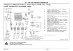
1
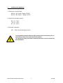
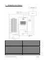
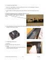
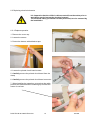
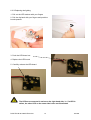
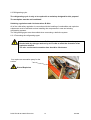
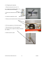
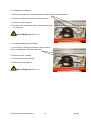
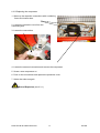
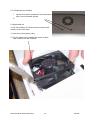
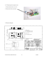
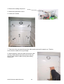
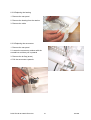
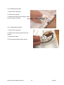
Service Manual
Wine chiller
© Electrolux Distriparts
Muggenhofer Straße 135
D-90429 Nürnberg
Germany
Fax +49 (0)911 323 1022
DGS-TDS-N
Edition: 05.06
Publ.-No.:
168 650
685
EN
Fitted wine chiller
WEK 7
Contents
1. Installing the Appliance ..................................................................... 3
2. Operating Functions.......................................................................... 4
3. Refrigeration Cycle Diagram ............................................................. 5
4. Troubleshooting ................................................................................ 6
5. Diagnosis Mode, Presentation Mode ................................................ 8
6. Replace Spare Parts ......................................................................... 9
DGS-TDS-N 05.2006 © Electrolux
2
168 650
1.
Installing the Appliance
1. Observe the correct width
550 mm, CH version- fittings 167603
600 mm, EU version – fittings 167678
2. Observe the climate classes
SN +10 - +32°C
N +16 - +32°C
ST +18 - +38°C
3. Electrical connection
220 … 240V 50 Hz alternating current
It is imperative that the chiller be disconnected from the mains prior to
work being carried out on the electrical system!
The electrical safety (accidental contact protection) is to be ensured by
the installation.
DGS-TDS-N 05.2006 © Electrolux
3
168 650
2.
Operating Functions
1. Switch appliance on/off
2. Temperature selection, top area -> (Can only be set if the
3. Temperature selection, bottom area
-> display flashes).
4. Supercool mode
5. Interior lighting on permanently or only when the door is open.
1
5
6
2
8
9
4
7
3
8
6. Temperature display for the top compartment
7. Temperature display for the bottom compartment
8. Mode display
9. Supercool on (flashes when the presentation activation)
10. Presentation mode
(pressing buttons 2 , 4 and 3 simultaneously activates and deactivates the presentation
mode).
11. Diagnosis
(pressing of all 4 temperature selection buttons activates the diagnosis mode).
Child-proof lock: the buttons are only active after they have been pressed
for 3 sec.
DGS-TDS-N 05.2006 © Electrolux
4
168 650
3.
Refrigeration Cycle Diagram
German
English
Bedienungseinheit
Beleuchtung
Türkontakt
Elektronik
Temperaturfühler - oben
Temperaturfühler - unten
Ventilator
Lamellenverdampfer
Servomotor
Heizung
Kondensator
Trockenpatrone
Kompressor
Operating unit
Lighting
Door contact
Electronic system
Temperature sensor - top
Temperature sensor - bottom
Ventilator
Lamellar evaporator
Servomotor
Heating
Capacitor
Dry cartridge
Compressor
DGS-TDS-N 05.2006 © Electrolux
5
168 650
4.
Troubleshooting
Fault
Possible cause
Remedy
Appliance not working
Appliance is not switched on
Switch appliance on.
Compressor 5 Min. forced
interruption for pressure
compensation
Insert plug.
Plug is not inserted or is loose.
Check or replace fuse.
Fuse is defect
Have power supply defect repaired
by an electrical specialist.
Power outlet is defect
Deactivate
Presentation mode is active
The chilling
temperature is
insufficient
Temperature is not correctly set
Please refer to the operating
functions.
Door was opened too long.
Do not leave the door open for longer
than 2-3 minutes (alarm sounds after
5 minutes and can be deactivated by
briefly pressing any button).
Ventilator defect
Replace ventilator (see 6.3.6 )
Inspect door seal
Replace door seal (see 6.1.4 ).
Appliance is next to a heat source
Glass door is cracked or broken
Please refer to "place of installation"
in the instruction manual.
Replace glass door (see 6.1.2).
Glass door is mounted canted
Adjust glass door (see 6.1.1).
Compressor defect, irregular
operating sound.
The repair is only to be carried out by
a workshop designed for this
purpose.
Risk of explosion
Interior lighting not
working
Light does not go out
LED is defect
Replace LED (see 6.2.2).
LED plug is not correctly inserted
Inspect plug-in connection (see
6.2.2).
Magnet missing of incorrectly fitted
Check light switch (see 6.1.3 ).
Sensor bent (magnetic field not
effective)
Align sensor (see 6.1.3 ).
Permanent mode activated
Deactivate permanent mode
DGS-TDS-N 05.2006 © Electrolux
6
168 650
Fault
Possible cause
Remedy
Insufficient
temperature
difference top/bottom
Temperature setting
Set correctly
Sealing lip missing from false floor
Fit sealing lip
False floor missing
Mount false floor
Heating defect
Air flap control defective
Inspect heating (see Diagnosis.
Replace if defect)
Inspect servomotor (see diagnosis)
Air flap jams
Remedy air flap malfunction
Cooling temperature
too cold
Sensors exchanged
Connect sensor correctly
Formation of
condensation on the
door
Error message F1 on
the operation panel
Increased atmospheric moisture
Wipe off with a dry cloth, set a little
warmer.
Top sensor defect
(Appliance does not function in the
emergency programme)
Replace sensor (see 6.3.11).
Error message F2 on
the operation panel
Bottom sensor defect
(Appliance does not function in the
emergency programme)
Replace sensor (see 6.3.11).
DGS-TDS-N 05.2006 © Electrolux
7
168 650
5.
Diagnosis Mode
Activation and deactivation by simultaneously activating the four buttons for the adjustment
of the target values (min. 3 sec.) . When the diagnosis mode is active, "tE“ alternates with the
ACTUAL temperature of the top sensor in the left-hand display and in the right-hand display,
the ACTUAL temperature of the top sensor alternates with the consumer status.
The temperature displays in Diagnosis Mode are not the average compartment temperatures
but the ACTUAL temperature at the sensor position.
The following functions are possible.
Compressor
Heating
on / off
on / off
"+" cold compartment
" - " cold compartment
Display CI / CO
Display HI / HO
The heating function is reset to "off" after 10 minutes for safety reasons.
Flap
Ventilator
open / closed "+" cold compartment Display SI / SO
on / off
" - " cold compartment
Display LI / LO
The Diagnosis Mode is automatically deactivated after 30 minutes for safety reasons.
The Diagnosis Mode can be deactivated at all times by switching the main switch off.
Presentation Mode
An operation mode is possible for presentations, by which the compressor, ventilator, heating
and air flap are not switched.
The Presentation Mode is activated and deactivated by simultaneously pressing the button
combination Target Value Adjustment"+" top, "Supercool" and target Value Adjustment
"+" bottom (min. 3 sec.)
"dE" is briefly displayed in the left-hand display after activation, "dA“ being briefly displayed
in the left-hand display after deactivation.
The target value adjustment, lighting, door switch and the door alarm remain active. The
"Supercool" function button only switches the LED but does not switch the compressor on
and off.
The target values are shown in the right-hand and left-hand display as ACTUAL values.
In order to control the "Presentation Mode" operating mode, the "Supercool" LED briefly
illuminates every 5 seconds or it is briefly extinguished if the "Supercool" is activated.
A switching off and on by means of the main switch or a power failure does not result in a
deactivation of the Presentation Mode.
DGS-TDS-N 05.2006 © Electrolux
8
168 650
6. Replacing Spare Parts
6.1 Door elements
6.1.1 Levelling out the door
1. An elongated hole is situated in the KS frame (top
and bottom) which can be used to adjust the door
height
2. An elongated hole is situated in the door (top and
bottom) which can be used to adjust the door in a
longitudinal direction
Ensure that the gap between the niche and the door is
the same all around.
6.1.2 Replacing the door
1. Remove the bottom and top covers
2. Remove the internal screw from the top and the
bottom
3. Loosen the external screw (do not remove)
4. Push the hinge out and then remove the door.
5. Mount the new door in the reverse order
2.
3.
4.
DGS-TDS-N 05.2006 © Electrolux
9
168 650
6.1.3 Inspecting the light switch
1. Switch the inside lighting of the door opening on (see No. 5 in the Operating Functions)
2. The operating display shows "OFF"
3. Close the door- the inside lighting should go off. Refer to 4 and 5 if the light does not go
off.
4. Remove the operation (see 6.2.1) and then check the sensor.
The sensor should be clearly bent as shown in the
photo. If necessary, bend it carefully of replace the
board.
5. Check the position of the door magnet if the inside lighting still does not go off, i.e. turn the
magnet in the magnet housing.
6.1.4 Replacing the door seal
1. Removal
Left the seal at the corner and pull it off
2. Fitting
Carefully press the seal in at the corners and travel
along the seal with the fingers
DGS-TDS-N 05.2006 © Electrolux
10
168 650
6.1.5 Replacing the handle
1. Lift the seal
2. Remove the cover cap
3. Loosen the screws with a Torx spanner
4. Remove the handle
5. Do not forget the plastic washers when mounting
the handle.
Only tighten the screws with a maximum torque of 1.5 Nm
- risk of glass breakage !!!
DGS-TDS-N 05.2006 © Electrolux
11
168 650
6.2 Replacing electrical elements
It is imperative that the chiller be disconnected from the mains prior to
work being carried out on the electrical system!
The electrical safety (accidental contact protection) is to be ensured by
the installation.
6.2.1 Replace operation
1. Remove the cover cap
2. Loosen the screws
3. Protect the buttons with adhesive tape
4. Loosen the printed circuit board screws
5. Carefully remove the printed circuit board from the
clamp
6. Carefully remove the printed circuit board connector
7. When installing the operation, ensure that the cable
protects the cable before the soldering tip and that the
sensor is not bent.
DGS-TDS-N 05.2006 © Electrolux
12
168 650
6.2.2 Replacing the lighting
1. Pull out the LED retainer with your fingers
2. Pull the clip back with your fingers and push the
board upwards
3. Push the LED-board out
4. Replace the LED-board
5. Carefully reinsert the LED-board
The LEDs are connected in series on the right-hand side, i.e. if a LED is
defect, the other LED on the same side is also not illuminated.
DGS-TDS-N 05.2006 © Electrolux
13
168 650
6.3 Refrigerating cycle
The refrigerating cycle is only to be repaired in a workshop designed for this purpose!
The workplace must be well ventilated!
Soldering regulations and risk instructions R 600a
All of the valid safety regulation in connection with the handling of combustible and explosive
substances must be adhered to when installing the compressors in new and existing
refrigerating systems.
The refrigerating agent must be avoided when evacuating a defective system.
6.3.1 Evacuating the refrigerating agent
After suction is carried out on a R 600a cycle, it is imperative that the system is
flooded with dry nitrogen and not by air in order to avoid the formation of an
explosive mixture!
The min. suction and evacuation time should be 30 minutes.
You require an evacuation pump for the
suction.
Risk of Explosion
DGS-TDS-N 05.2006 © Electrolux
14
168 650
6.3.2 Replacing the evaporator
1. Remove rear panel cover (se 2.3.7)
2. 2. Open the rivet head by drilling it out
with a ø6 bit (only the rivet head)
3. Remove the board with the rest of the
rivet
4. Loosen the evaporator screws
5. Warm up the connections with a soldering frame and loosen it
6. Pull the evaporator out of the inside retainer
7. Bend and screw on the new evaporator
8. Lace in the lines, replace the leading-in tube (Art.
No. 126221).
9. Solder the lines in place.
DGS-TDS-N 05.2006 © Electrolux
15
168 650
6.3.3 Replace the capacitor
1. Warm up the capacitor connections with a soldering flame and loosen them
2. Loosen the screwed connections of the capacitor
3. Screw on a new capacitor
4. Reconnect the connections to the compressor and the
dry cartridge
Risk of Explosion (see 6.3.1)
6.3.4 Always replacing dry cartridges
1. Cut-off the dry cartridge connections directly above
the dry cartridge with a special cutting tool.
2. Remove the dry cartridge
3. Position the new dry cartridge
4. Solder the dry cartridge on
Risk of Explosion (see 6.3.1)
DGS-TDS-N 05.2006 © Electrolux
16
168 650
6.3.5 Replacing the compressor
1. Warm up the capacitor connections with a soldering
flame and loosen them.
2. Loosen the protective cover from the
connecting box.
3. Loosen the connections
4. Loosen the screwed connection and remove the compressor
5. Screw a new compressor on
6. Push on the connections and replace the protective cover
7. Solder the tubes on again
Risk of Explosion (see 6.3.1)
DGS-TDS-N 05.2006 © Electrolux
17
168 650
6.3.6 Replacing the ventilator
1. Lift the cover with a screwdriver (use the bottom
slits), lever the handle upward
2.
2. Break cable out
3. Pull the ventilator off. Ensure that the rubber knob
remains on the rear panel
4. Insert the new ventilator cable.
5. Pull the rubber knob upwards with a pair of pliers
until it latches into the ventilator.
DGS-TDS-N 05.2006 © Electrolux
18
168 650
6.3.7 Removing the rear panel cover
1. Screw the electronics cover off
2. Remove all of the connectors
3. Electronics diagram
DGS-TDS-N 05.2006 © Electrolux
19
168 650
4. Remove the sealing compound
5. Remove the protective covers
6. Loosen all 5 screws
7. Take hold of the rear panel through the slide opening and pull it towards you. Thereby
ensure that the cables do not get caught.
8. When replacing, insert the cable through the cable
opening. Initially insert the centre screw in the rear
panel. Finally seal the cable opening with sealing
compound.
DGS-TDS-N 05.2006 © Electrolux
20
168 650
6.3.8 Replacing the heating
1. Remove the rear panel
2. Remove the heating from the retainer
3. Remove the cable
6.3.9 Replacing the servomotor
1. Remove the rear panel
2. Loosen the servomotor retainer with the
screwdriver and then pull it upwards
3. Remove the air flap (arrow)
4. Pull the servomotor upwards
DGS-TDS-N 05.2006 © Electrolux
21
168 650
6.3.10 Replacing the slide
1. Remove the rear panel
2. Remove the springs
3. Remove the slide and in doing so, lightly
press the panel outwards
6.3.11 Replacing the sensor
1. Remove the rear panel
2. Remove the sensor upwards from the
retainer
3. Remove the cable
4. Do the same with the bottom sensor
DGS-TDS-N 05.2006 © Electrolux
22
168 650