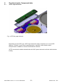
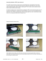
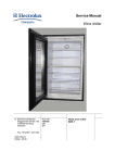
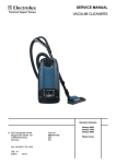
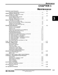
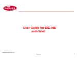
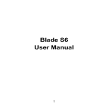
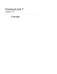
1
SERVICE MANUAL
Hobs
with
© Electrolux Distriparts
Muggenhofer Straße 135
D-90429 Nürnberg
Germany
Fax +49 (0)911 323 1022
DGS-TDS-N
12.07
Edition:
Publ.-Nr.:
599 531 461
685
EN
„KITE“
Input electronic
Table of contents
1.
ESD=electrostatic discharge ...................................................................................... 3
2.
2.1
2.2
2.2.1
2.2.2
2.3
2.3.1
2.3.2
Software specifications, functions .............................................................................. 4
Appliance variants ...................................................................................................... 4
Button / and display layouts ....................................................................................... 5
„KITE“ Bar graph Variante ......................................................................................... 5
„KITE“ 7 Segment Variant ......................................................................................... 6
Main features of operation ......................................................................................... 7
Appliance On and Off connection .............................................................................. 7
Child safety function ................................................................................................... 7
3.
Automatic Shut-Off ..................................................................................................... 8
4.
4.1
4.2
Functional parts, Component data ............................................................................. 9
„KITE“ Input electronic ............................................................................................... 9
„HOC 2010“ power electronics for radiation-heated hobs ........................................ 11
5.
5.1
5.2
5.2.1
5.2.2
Fault diagnosis ......................................................................................................... 12
What to do if ...? ....................................................................................................... 12
Alarmmanagement (Faultcodes) .............................................................................. 13
Error codes for hobs with radiation-heated cooking zones ...................................... 13
Error codes with hobs with induction heating ........................................................... 13
6.
Demo Mode/ Service Mode/ Alarm Error Mode ....................................................... 13
DGS-TDS-N 12.07 U. H. / A. B. © Electrolux
-2-
599 531 461
EN
1.
ESD=electrostatic discharge
As the single electronic interfaces are not protected internally against statical electricity and are
partially open, you must pay attention to that, in case of a repair, there will be a potential
compensation via the housing of the appliance (touch it) in order to neutralize a possible
charging and to prevent a damaging of the affected electronic interface.
You also have to be careful with those electronics delivered as spare parts, which have to be put
out of the ESD protective package only after a potential compensation (discharge of possible
statical electricity).
If a potential compensation with an existing static electricity is not executed, it does not mean
that the electronic is demaged directly. Consequential damages may result due to the damaging
of internal structures which arise only in case of load through temperature and current.
Endangered are all assembly groups which are provided with control entries, wire paths lying
open and free-accessible processors.
DGS-TDS-N 12.07 U. H. / A. B. © Electrolux
-3-
599 531 461
EN
2.
Software specifications, functions
2.1
Appliance variants
„KITE“ Bar graph Variant
„KITE“ 7 Segment Variant
Sample Illustration
DGS-TDS-N 12.07 U. H. / A. B. © Electrolux
Sample Illustration
-4-
599 531 461
EN
2.2
2.2.1
Button / and display layouts
„KITE“ Bar graph Variante
1
2
7
6
2
7
1
2
3
4
5
6
7
8
9
3
4
5
8
9
7
2
7
2
Locking/child safety lock with display
Additional multizone or additional connection of special functions with LED, depending on
appliance class/make
Light elements for the cooking stage display
Cooking zone displays (LED) timer function
Timer display, 2x 7 segment displays
On/Off with display
Cooking zones status displays (LED) depending on appliance class/make
- Pot recognition
- Automatic deactivation
- Residual heat ...
Timer operation
Cooking stage selection
Sample Illustration
DGS-TDS-N 12.07 U. H. / A. B. © Electrolux
-5-
599 531 461
EN
2.2.2
„KITE“ 7 Segment Variant
1
2
7
6
2
7
1
2
3
4
5
6
7
8
3
4
5
7
2
8
7
2
Locking/child safety lock with display
Additional multizone or additional connection of special functions with LED, depending on
appliance class/make
Cooking stage selection
Cooking zone displays (LED) timer function
Timer display, 2x 7 segment displays
On/Off with display
Cooking zones status displays (LED) depending on appliance class/make
Timer operation
Sample Illustration
DGS-TDS-N 12.07 U. H. / A. B. © Electrolux
-6-
599 531 461
EN
2.3
2.3.1
Main features of operation
Appliance On and Off connection
Switch on:
Switch off:
-Touch "ON" sensor panel for 1 second. Pilot light illuminates.
-Touch "OFF" sensor panel for 1 second. Pilot light illuminates.
After activation, a cooking stage or a function must be set within 10 seconds or the appliance
switches off automatically.
2.3.2
Child safety function
The child safety lock prevents an undesirable use of the appliance.
Switching child safety function on
-
Switch appliance on with the `ON´ safety switch (do not set a cooking stage).
Press the child safety lock button for 4 seconds. Display "L". The child safety device is
activated.
Bypassing the child safety lock
With this, the child safety lock can be deactivated for a single cooking process; it continues to
remain active afterwards.
-
Switch appliance on with the `ON´ safety switch (do not set a cooking stage).
Press the child safety lock button for 4 seconds. Display "L".
It can be used one more time until the next deactivation of the appliance. After the child safety
device has been bypassed a cooking stage or function must be set within approx. 10 seconds,
otherwise the appliance switches off automatically.
Switching child safety function off
-
Activate the appliance with the "ON" sensor button.
Press the child safety lock button for 4 seconds. Display "L".
Appliance switch off. The childproof lock is deactivated.
DGS-TDS-N 12.07 U. H. / A. B. © Electrolux
-7-
599 531 461
EN
3.
Automatic Shut-Off
Hob
-
If you do not set a cooking level in a cook zone within approx. 10 seconds after switching
on of the cook field, the cook field switches off automatically.
If one or more sensor fields are covered longer than 10 seconds, e.g. by a pot placed on
it, a signal sounds and the cook field switches off automatically.
If all cook zones are switched off, the cook field switches off automatically approximately
10 seconds later.
Control panel
-
If one or more sensor panels in the operating panel should be covered for more than 10
second when the appliance is switched off, a buzzer sounds. The buzzer switches itself off
automatically when the sensor panels are no longer covered.
Cooking zones
-
If one of the cook zones is not switched off after a certain time or if the cook stage is not
changed, the appropriate cook zone switches off automatically. „- “is displayed. Before
renewed use the cook zone must be set to „0 “and be cooled down.
cooking level
The cooking zones are disconnected with
1-3
4-6
7-8
9-14
6 Hours
5 Hours
4 Hours
1,5 Hours
DGS-TDS-N 12.07 U. H. / A. B. © Electrolux
-8-
599 531 461
EN
4.
Functional parts, Component data
4.1
„KITE“ Input electronic
Fig.: „KITE“ Bar graph Variante
Depending on the "KITE" type, "KITE" input electronic mainly comprises one or more LED
displays, 4 "sliders" (touch control operating strips), capacitive sensor buttons and a
microprocessor in addition to diverse semiconductor modules.
"KITE" controls both radiation-heated hobs with HOC power electronic and hobs with induction
heating.
DGS-TDS-N 12.07 U. H. / A. B. © Electrolux
-9-
599 531 461
EN
Assembly situation „KITE“ input electronic
The `KITE´ input electronics system can be accessed after the top glass/top trough frame
connecting screws have been loosened and the top glass has been lifted off; it can now be
easily removed together with the silicone sealing mat. This is valid for both radiation-heated
hobs and hobs with induction heating.
The silicone sealing mat is enclosed with the configured `KITE´ input electronics spare part. It is
imperative that this also be replaced and carefully fitted in order to ensure the tightness of the
electronics. The `KITE´ input electronics must be exactly fitted in the mat. Check that the cable
sleeve is correctly positioned before closing the top.
Sample Illustration Induction hob
With radiation-heated hobs, the HOC power electronics can be accessed after the silicone
frame has been removed. Please refer to Service Manual 599 519 523 for further information on
the servicing of induction hobs.
DGS-TDS-N 12.07 U. H. / A. B. © Electrolux
- 10 -
599 531 461
EN
4.2
„HOC 2010“ power electronics for radiation-heated hobs
The `HOC 2010´power electronics comprises a row of relays, a transformer and other
components which are required to supply power to the relays and the input electronics. It
receives the electrical control signals which are transmitted by the input circuit board and
supplies the corresponding radiator with power depending on the impulses.
Each of the connector lugs and relays are designated on the circuit board. These designations
are also on the circuit diagrams.
Assembly situation
DGS-TDS-N 12.07 U. H. / A. B. © Electrolux
- 11 -
599 531 461
EN
5.
Fault diagnosis
5.1
What to do if ...?
Problem
The cooking zone cannot be
switched on or is not
functioning
Possible cause
More than 10 seconds have
passed since the appliance
was switched on
The child safety lock is
activated
Numerous sensor panels
were touched simultaneously
Automatic deactivation has
been triggered
There is water on the
operating panel or the
operating panel is covered
by fat splashes
Stop + Go is active
Buzzer sounds when
The operating panels
appliance is switched off
completely or partially
covered by objects.
There is water on the
operating panel or the
operating panel is covered
by fat splashes
The residual heat display
The cooking zone has only
does not display anything
been on for a short time and
is therefore not hot yet
The On/Off sensor panel has
The buzzer sounds and the
appliance switches itself on
been covered up, e.g. by a
and off again after 5 sec.; the cloth
buzzer sounds again after 5
sec.
"-" is illuminated
Automatic deactivation has
been triggered
"E“ and a number are
displayed
Electronics error
"?“ is illuminated
Automatic deactivation has
been triggered
DGS-TDS-N 12.07 U. H. / A. B. © Electrolux
- 12 -
Remedy
Switch appliance back on
Deactivate the child safety
lock (see chapter "child
safety lock")
Only touch one sensor panel
Remove any objects (pot,
cloth, etc.) from the
operating panel, switch
appliance back on
Wipe over operating panel
Deactivate Stop + Go
Gegenstände entfernen
Wipe over operating panel
Contact customer service of
the cooking zone is hot
Do not place any objects on
the operating panel
Switch cooking zone off,
switch cooking zone back on
again
Disconnect the appliance
from the mains for a few
minutes (remove the fuse
from the house fuse cabinet).
if "E" isstill displayed after
switching back on, contact
customer service
Switch cooking zone off and
then back on again
599 531 461
EN
5.2
5.2.1
Alarmmanagement (Faultcodes)
Error codes for hobs with radiation-heated cooking zones
Error code
E0
Error description
Configuration alarm
E1
Input electronic configuration
error
Cooling fan not connected or
blocked
E7
5.2.2
E8
Disturbed communication
between the input electronic
and power electronic
E9
Internal electronics error
Error remedy
Disconnect the appliance
from the mains, wait 10
seconds and restore power.
replace power electronic is
error still displayed
Replace input electronic
Check the cooling fan
induction module and
replace if necessary
Check the conencting cable
and replace if necessary,
replace input electronic if
unsuccessful-> Replace
power electronic
Replace power electronic
Error codes with hobs with induction heating
Please refer to Service Manual 599 519 523 for explanations on error displays in induction hobs.
6.
Demo Mode/ Service Mode/ Alarm Error Mode
The deactivated state of the hob is the starting position.
Activate the On/Off sensor button for 3 seconds.
Activate the additional multizone connection/additional function connection sensor buttons for
both of the right cooking zones for 3 seconds. Note: the sensor buttons are not visible when
deactivated. Please refer to the manual for the exact position of the buttons. Confirmation with
an acoustic signal (2x "beep").
Pressing the timer sensor button once = DEMO MODE. This is shown by a "d" in the left timer
display.
Pressing the timer sensor button twice = SERVICE MODE. This is shown by an "s" in the left
timer display.
Pressing of the timer sensor button three times = ALARM/ ERROR MODE.
Pressing of the timer sensor button four times = return to DEMO MODE.
If a sensor button is not activated, the normal deactivation times described in Chapter 2 have
validity.
DGS-TDS-N 12.07 U. H. / A. B. © Electrolux
- 13 -
599 531 461
EN
6.1
Demo Mode
Timer display left „d“ = Demo Mode
Timer display right „“ = Demo Mode off
The Demo Mode is activated by pressing the „Timer +“ sensor panel.
Timer display left „d“ = Demo Mode
Timer display right „o“ = Demo Mode on
The hob can now be used as normal but without a heat output
The demo Mode is deactivated by pressing the „Timer +“ sensor panel again.
Timer display left „d“ = Demo Mode
Timer display right „“ = Demo Mode off
The hob can now be used as normal with a heat output
6.2
Service Mode
The Service Mode is activated by pressing the „Timer +“ sensor panel.
Timer display left „s“ = Service Mode.
-
6.3
The function of all LEDs and displays is tested for 5 seconds.
The software version and the input electronic version are displayed in the timer display for
5 seconds.
The software version of the power electronic is displayed in the timer display for 5 seconds
Alarm Error Mode
The Alarm Menu is activated by pressing the „Timer +“ sensor panel.
Timer display left „E“ = Error Mode.
Each of the last five error codes to occur are shown for 5 seconds.
DGS-TDS-N 12.07 U. H. / A. B. © Electrolux
- 14 -
599 531 461
EN