1
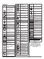
Integrated Power Console (IPC™)
Models EC300 and 1898001
Service Manual for Console and Attachments
Rx Only
Notice
This manual is provided primarily for information purposes. Although there
are certain troubleshooting actions that may be attempted by the customers
as specifically listed in this manual, all repairs must be undertaken by
Medtronic Xomed or its authorized representative.
Released documents are available for viewing/printing @ www.medtronicENT-TechComms.com
™ are trademarks and ® are registered marks of Medtronic, Inc.
The information contained in this document was accurate at time of publication. Medtronic reserves the right to make changes in the product
described in this manual without notice and without incorporating those changes in any products already sold.
Symbols......................................................................................................................4
General........................................................................................................................5
Definitions ................................................................................................................5
Warnings and Precautions...................................................................................5
Warnings................................................................................................. 5
Precaution............................................................................................... 5
System Description.................................................................................................5
Sales and Customer Care......................................................................................5
U.S. Customers........................................................................................... 5
Medtronic Xomed, Inc. ............................................................................ 5
U.S. Help Line........................................................................................ 5
Medtronic Powered Surgical Solutions................................................... 5
U.S. Help Line........................................................................................ 5
International Service................................................................................. 5
Console Front............................................................................................. 6
Connector Panel.................................................................................... 6
Connector Panel Cable Connection................................................... 6
Connector Panel Cable Disconnection (multi pin).......................... 6
Cable Disconnection (single pin)........................................................ 6
Console Rear............................................................................................... 7
Power Cords................................................................................................ 7
Console Pump Designator........................................................................ 7
Irrigation/Coolant Pumps........................................................................ 7
Pump Cartridge Set-up......................................................................... 7
Visao® Pump Cartridge......................................................................... 7
Visao® Coolant Pump Set-Up............................................................... 8
Standard Pump Set-up.......................................................................... 8
Accessories/attachments.....................................................................................8
Multifunction Foot Control Unit (FCU)................................................ 8
Intelliflow Irrigation Remote Control..................................................... 8
Endo-Scrub® 2 ........................................................................................... 8
Endo-Scrub® 2 Assembly...................................................................... 9
Suction Irrigator......................................................................................... 9
Suction Irrigator Adapter Kit................................................................... 9
Handpieces Microdebriders and SC1...............................................................9
StraightShot® M4, Microdebriders, and Midas Rex® SC1..................... 9
Technical Specifications........................................................................ 10
StraightShot® Magnum® II and StraightShot® III Microdebriders.... 10
Technical Specifications........................................................................ 10
Handpieces Drills.....................................................................................................10
Visao® High-Speed Otologic Drill (Water-Cooled).......................... 10
Technical Specifications........................................................................ 10
Skeeter® Ultra-Lite Oto-Tool System Set-Up and Use...................... 10
Technical Specifications........................................................................ 10
Midas Rex® Legend EHS® Motor......................................................... 10
Technical Specifications........................................................................ 11
Midas Rex® Legend EHS Stylus® Motor ............................................. 11
Technical Specifications........................................................................ 11
To Rotate the Finger Lever........................................................................ 12
Technical Specifications........................................................................... 12
Splash Screen.............................................................................................. 12
Settings Screen............................................................................................ 12
Handpiece Default Settings Table............................................................ 13
Console Set-Up ......................................................................................... 13
Connect Handpiece/Footswitch Screen.................................................. 13
Console Set-Up Instructions.................................................................... 13
Power Down........................................................................................... 14
Cleaning.................................................................................................. 14
Console Specifications............................................................................... 14
3
Symbols
N
Serial Number
Do not dispose of this product
in the unsorted municipal
waste stream. Dispose of
this product according to
local regulations. See http://
recycling.Medtronic.Com
for instructions on proper
disposal of this product.
Do not use if package is open
or damaged
Package Contents
1
2
Manufacturer
Date of Manufacture
>120 VAC
ON
<120s
OFF
>180s
<XX° C
XX° C
XX° C
>X° C
Pump Head 2
105345
Use by Date
Do not Reuse
Lot Number
REF
REF
Use with
This device complies with
medical device directive
93/42/EEC
0086
Rx Only
Caution: federal law (U.S.A.)
Restricts this device to sale by
or on the order of a physician
! USA
USA Only
Quantity
Instrument Case
Instrument case
Lubricant/Diffuser
Lubricant/Diffuser
Dissecting Tool
Dissecting Tool
Attachment Attachment
Control Unit Control Unit
Protective Earth
Refurbished Refurbished
Accessory Accessory
Consult instructions for use
Sterilized by ethylene oxide.
STERILE EO Do not use if package is open
or damaged
Authorized representative
E C R E P in the
european community
0123
Conforms to ANSI/AAMI
ES 60601-1, IEC/EN 606011. Certified to CSA C22.2
No.601.1
Handpiece
Skeeter® handpiece
EUR · USA · JPN · AUS
AC power
4
On/Off (main power)
Catalog Number
Sterilized by radiation. Do
STERILE R not use if package is open or
damaged
STERILE Non sterile
Unlocked
Recommended storage
temperature and limits.
Equipotential
Is approximately equal to
Locked
Applied part duty cycle
Accessory
Output
Top foot control unit button
Not greater than 120VAC
EMC compliance mark
Fuse
ACC
Right foot control unit button
ROHS - Environmental
friendly use period
- China (SJ/T113642006.)
Pump Head 1
LOT
Left foot control unit button
Attention see instructions
for use
IPX1
IPX7
M
Protected against vertical
water drops
Protected against the effects
of temporary immersion in
water
Type BF applied part
Manual Start/Stop
RF transmitter (interference
may occur)
Precaution: Pinch hazard.
Keep fingers clear of rollers
BUR
STIM BUR connector
NIM
NIM® console connector
EHS
Electrical high speed
handpiece connector
Foot pedal connector
Fr
World Wide Standard for
medical tubing diameter.
Fine irrigant adjustment
Regulator Regulator
Bone Mill Bone Mill
Motor
Motor
Brush
Brush
Adapter
TOOL
TUBE
Adapter
Tool control
Tube control
Multi-Use Disposable Attachment
Multi-Use Disposable
Attachment
NOTE
IT IS IMPORTANT THAT THE
OPERATOR BE FAMILIAR WITH
THIS MANUAL AND THE USER’S
GUIDE WITH THEIR WARNINGS,
PRECAUTIONS, PROCEDURES AND
SAFETY ISSUES.
General
Uppercase Alphabetic list (A. B. C. etc.) contain introductory
information where Numeric list (1. 2. 3. etc.) are “How To” instructions.
Definitions
Explaining the essential meaning of a word or acronym as used in this
manual.
Also explains changes in words or phrases variations from one product
generation to the next.
FCU – Foot Control Unit
IPC™ - Integrated Power Console
I.V. -
Intravenous
NIM® - Nerve Integrity Monitor - One or all of the following
units: NIM-Response®, NIM-Pulse®, NIM-Response®
2.0, NIM-Pulse® 2.0, NIM-Neuro® 2.0, NIM-Response®
3.0, NIM-Pulse® 3.0, NIM-Neuro® 3.0
Nomenclature The act or process or an instance of naming
Warnings and Precautions
Warnings
W1 The IPC™ shall only be serviced by trained technicians at an
authorized Medtronic service facility
W2 The IPC™ contains live circuitry that can cause injury or death if
the enclosure is opened.
W3 The IPC™ contains live circuitry that can cause injury or death
to operators or patients if assembled incorrectly. This document
and the documents referenced herein are not sufficient to
guarantee correct assembly and operation of the device. Product
specific training and product specific test equipment is required
to ensure the correct operation and assembly of the IPC™.
W4 This system requires insulated connectors for the StraightShot®
M4 Microdebrider, StraightShot® Magnum® II Microdebrider,
StraightShot® III Microdebrider, Midas Rex® SC1, Visao®, or
Skeeter® handpieces and the Multi Function Foot Control Unit.
W5 Auxiliary Power Outlet with protective cover is for use with the
HydroDebrider™, or Bone Mill consoles only.
W6 Sterilize and dry reusable device before storing the system.
Decrease likelihood of cross-contamination with timely
sterilization.
W7 After each procedure, properly clean all reusable system
components.
W8 Auxiliary Power Outlet with protective cover is for use with the
HydroDebrider™, or Bone Mill consoles only.
Precaution
P1 Prime/Flush Priming is a feature designed to purge air out of the
tubing set(s) during setup. The first time a Prime or Flush button
is pressed it will turn on pump 1 and/or 2 long enough to purge
air out of the tubing set(s). Turning power Off and On resets the
Prime feature. Once pressed all Prime buttons will change to Flush
buttons.
System Description
The IPC™ System is a powered microdebrider, drill and saw system
that will remove soft tissue, hard tissue, bone, and biomaterials during
surgical procedures. The system consists of a power control console,
footswitch, connection cables, and assorted handpieces to drive various
burs, blades, drills, rasps, cannulae, and saws. It includes integrated
irrigation pumps for irrigation of blades, burs and for motor coolant.
The Nerve Integrity Monitor (NIM®) is a separate device that stimulates
and monitors the nerve. This system has connections that allow the
NIM® to be connected with the Visao® handpiece and Stimulating Bur
Guard enabling the NIM® to stimulate and monitor the nerve at the
surgical site.
The system can be used to clear the end of a rigid rod endoscope in
order to maintain good visualization of endoscopic procedures without
having to remove the scope from the surgical site.
This device is intended for use by physicians trained in the procedures
described.
Sales and Customer Care
Medtronic is committed to provide the highest standard of
workmanship in manufacturing its products. Your system requires
minimal maintenance and calibration.
Servicing and/or modification to the system, or any accessory/
attachment by anyone other than qualified service personnel may
significantly compromise the systems performance and void the
equipment warranty. For best performance, it is recommended that all
service be performed by Medtronic Xomed service personnel.
Medtronic recommends preventative maintenance and screen
calibration scheduled at yearly intervals. Comprehensive testing and
calibration should be performed by returning the entire system to
Medtronic Customer Service.
U.S. Customers
Should your console or related equipment malfunction, Medtronic
provides, at no charge, loaner equipment shipped to your facility by UPS
or Federal Express for use while your equipment is being serviced by
Medtronic. Please adhere to the following guidelines:
1. When a loaner console is ordered, please reuse the shipping material
and carton when you return your console to Medtronic. Insure the
unit.
2. When a loaner is not ordered, please package the console as safely as
possible and insure.
3. A return goods authorization number is required on repairs. A copy
of your purchase order is required. Make certain the purchase order
includes the following:
• Shipping and billing information
• Purchase order number
• Contact person
• Phone number
• Description of malfunction
• Your Medtronic account number
4. Please indicate preferred method of return shipment. Otherwise the
unit will be shipped back via UPS ground.
5. When the malfunctioning unit is not covered by warranty,
Medtronic will contact your facility promptly with a repair cost
estimate if requested. The customer will be responsible for freight
charges on non-warranted units.
6. When you have loaner equipment and you receive your repaired
unit, please package the loaner equipment as safely as possible
using the foam provided with your repaired equipment. Include
paperwork indicating the unit is a loaner, and Medtronic will credit
your account.
7. Loaner equipment not received by Medtronic within 30 days from
the date that repaired equipment is shipped will be invoiced at full
purchase price.
Medtronic Xomed, Inc.
6743 Southpoint Drive North
Jacksonville, FL 32216 USA
WWW.medtronicENT.com
U.S. Help Line
(800)-874-5797.
Medtronic Powered Surgical Solutions
4620 North Beach Street
Fort Worth, TX 76137 USA
WWW.medtronic.com
U.S. Help Line
(800) 468-9710
International Service
International customers should contact their local Medtronic
representative.
5
Console Front
Connector Panel Cable Disconnection (multi pin)
To Remove Midas Rex® :
To Remove Midas Rex® Legend EHS® Motor and Legend EHS
Stylus® Motor, Cable from motor or console:
A
A
B
1
2
1. Push the cable towards the motor or console.
2. Then pull out by locking ring (A).
To Remove Midas Rex® Legend EHS Stylus® Cable from console:
A
C
E
Push the cable towards the console, then pull by locking ring (A)
To Remove cables (multi pin) with polymer insulating
boots:
D
1
A.
B.
C.
D.
E.
Touchscreen – User interface.
Pump 1 – Coolant, lens cleaning, or irrigation.
Pump 2 – Irrigation.
Connector Panel - peripheral devices.
Power Switch – System On/Off switch.
2
A
Connector Panel
E
A
Port #
A
B
C
D
E
F
G
H
B
C
D
F
G
Component
Midas Rex® Legend EHS® motor
Midas Rex® Legend EHS® Stylus motor
StraightShot® M4 Microdebrider
Midas Rex® Legend EHS® Stylus Touch™ motor
Midas Rex® SC1
StraightShot® Magnum® II and StraightShot® III
Visao®
Stimulus input from Patient Interface
connection (NIM).
Stimulus output to STIM Bur Guard
Skeeter® Handpiece
Endo-Scrub® 2 Finger Switch
Endo-Scrub® 2 Footpedal
IntelliFlow Irrigation Remote Control
Foot Control Unit (FCU)
NOTE: Confirm handpieces contain polymer insulating boot (A).
If handpiece contain missing or cracked polymer boots, contact
Medtronic Customer Care for upgrade.
NOTE, If units with polymer insulating boots have debris under
the insulator:
• Reclean according to Cleaning and Sterilization instructions.
• If debris was not removed return for warranty servicing.
See warning W4.
1. Push the cable towards the console.
2. Then pull out by the polymer insulating boot (A).
H
Quantity
1
1
2
1
1
1
1
1
1
Connector Panel Cable Connection
Cable to console connection red/silver dot:
• Red or silver dot connections are multi pin and must be correctly
aligned (oriented).
Cable to console connection without dot:
• Connectors without the red or silver dot are single pin and may
be inserted without regard to orientation.
6
To Remove cables (multi pin) with silicone insulating
boots:
Silicone insulated connectors do not have a locking device (ring) and
may be removed by pulling straight out on the connector.
Cable Disconnection (single pin)
Single pin connectors do not have a locking device (ring) and may be
removed by pulling straight out on the connector.
Console Rear
Console Pump Designator
A
B
C
D
E
G
H
I
F
A.
B.
C.
D.
E.
Pole clamp.
Compact flash card port (factory use only).
Manual Start/stop button.
Fuse Access – Replace only with 5 x 20 T. L. 5A, 250 V fuse.
Auxiliary power outlet with protective cover:
• For use at grid voltage < 120 VAC only.
• HydroDebrider™, or Bone Mill consoles only. See warning W5.
F. To remove cover, place small screwdriver in notch at bottom and
pull/pry off.
G. Endo-Scrub® 2 - power connector.
H. Power cord connector: See sppendix B for part numbers.
• Hospital grade power cord connects here.
• Means of disconnecting device from Mains voltage by the power
cord.
I. Equipotential:
• Uniform potential.
• Means for eliminating noise or interference with sensitive
equipment by application of a POTENTIAL EQUALIZATION
CONDUCTOR.
Power Cords
North America:
United Kingdom,
Continental Europe:
USA, Barbados,
Ireland, Hong
Austria, Belgium, Finland,
Belize, Bolivia,
Kong, Malaysia, France, Germany, Greece,
Canada, Columbia,
Singapore
Korea, Luxembourg,
Ecuador, Venezuela P/N EA606 or
Netherlands, Norway,
Standard P/N EA600
1895821
Portugal, Spain, Sweden
or 1895820
P/N EA602 or 1895822
6 meter P/N EA650
or 189721
China
India, South
Switzerland
P/N EA604
Africa
P/N EA601
P/N EA607
Argentina
Israel
Denmark
P/N EA608
P/N EA609
P/N EA610
Australia, New
Japan
Italy, Chile
P/N EA611
Zealand
P/N EA603 or
P/N EA605
1895823
A. P
ump 1: Coolant, lens cleaning, or irrigation.
B. Pump 2: Irrigation or lens cleaning.
C. Pump 1 Designator – This designator number is used to coordinate
the pump (by number) with the cartridge number and/or pump setup screen number listed on the touch screen. When setting up the
console these numbers must match.
D. Pump 2 Designator.
NOTE: Not all Pump Cartridges have pump designator numbers.
For these cartridges the operator should view the Pump Setup
Screen prior to installing the cartridge.
Irrigation/Coolant Pumps
Pump Cartridge Set-up
The Pump Cartridge snaps onto the lower section of the pump.
1
2
3
Visao® Pump Cartridge
The Visao® Pump Cartridge has both a pump tube and a return tube.
A
B
C
A. Pump tubing.
B. Pump tubing is clipped into the Pump Cartridge.
C. Return tube.
7
Visao® Coolant Pump Set-Up
The Pump Cartridge snaps onto the lower section of pump # 1.
1
3
2
Standard Pump Set-up
Microdebrider
A. Pedal: Start/stop, variable speed (start/stop, or variable speed
selectable via FCU button on Main Screen).
B. Right Button: In OSC Mode this button will rotate inner blade
60°/180º (touchscreen selected). In FWD Mode this button will
select Pedal function (Start/stop, or variable speed).
C. Top Button: Active handpiece selection.
D. Left Button: Mode/RPM selection SC1
A. Pedal: Start/stop, variable speed (start/stop, or variable speed
selectable via FCU button on main screen).
B. Right Button: If mode is set to OSC this button will, rotate inner tube
on blades 180º. If mode is set to FWD this button will, select pedal
function (Start/stop, or variable speed).
C. Top Button: Active handpiece selection.
D. Left Button: Mode selection -FWD/OSC
NOTE: If any of these condition are different check your set-up, if
still incorrect contact Customer Service.
Intelliflow Irrigation Remote Control
3
2
1
Tips on loading the pump
Accessories/attachments
Multifunction Foot Control Unit (FCU)
Part No. 1898430 or EF200
D
A. Pause/On-Off:
• Pause if used with handpiece irrigation (Flow
rate will flash yellow).
• On-Off/Pause if used with Suction
A
Irrigator.
B. Increase/Decrease:
B
• Handpiece Irrigation - fine adjustment for
irrigation rate.
C
• Suction Irrigator - fine adjustment for
irrigation rate.
C. Increase/Decrease:
• Handpiece Irrigation - coarse adjustment for
irrigation rate.
• Suction Irrigator - selects stainless steel (Fr)
tubing size.
Endo-Scrub® 2
NOTE: Can be used only with a microdebrider.
The IPC™ System incorporates Endo-Scrub® 2 functionality by using
irrigation pump number one (1) and controlling operation with the
touch screen and an external footswitch or finger switch.
It is not to be used for infusion, for disinfection or sterilization of an
endoscope, or for suction removal of blood and debris.
NOTE: Use the Endo-Scrub® 2 sheath only with an endoscope
listed on the sheath product label, as malfunction or poor
performance could result.
B2
1
A
C
A
4
D
Aa
B
Buttons and Pedal
NOTE: Each button must be depressed and held for a definable amount of
time (100 mS by default).
Drills
A. Foot Pedal - Start/Stop, Variable speed.
Aa. Non-Slip Foot Pad.
B. Right Button - Pedal function, (Start-Stop or Variable speed).
C. Top Button - Active handpiece selection
D. Left Button - Mode selection, (FWD/REV).
8
C3
A.
B.
C.
D.
Endo-Scrub® 2 Sheath.
Endoscope.
Light source connection.
Irrigation connection.
E5
E. Endo-Scrub® 2 Finger switch.
F. Finger switch cable.
F6
Suction Irrigator Adapter Kit
7
G
8
H
C3
G. Endo-Scrub® 2 Footswitch.
H. Endo-Scrub® 2 Footswitch cable.
B2
A1
4
D
Endo-Scrub® 2 Assembly
1
2
A. Blue Irrigation Tube Adapter fits high speed irrigation tubing 3318503.
B. White Irrigation Tube Adapter fits IPC™ Visao® irrigation tubing 3318603.
C. Irrigation Connector Set is used to adjust the Blue or White Adapter
to the stainless steel Irrigation Fitting.
D. Irrigation Fitting.
Handpieces Microdebriders and
SC1
1. Wet.
2. Slowly insert.
3
StraightShot® M4, Microdebriders, and
Midas Rex® SC1
2
B
1
A
3. Attach irrigation and light source.
Suction Irrigator
7
G
A.
B.
C.
D.
E.
F.
G.
4
D
E5
The Suction Irrigator may be selected via the radio button within the
Irrigation Method box.
NOTE: The suction irrigator is NOT available for microdebrider
handpieces.
Suction Irrigator Handpiece.
C3
F6
Handpiece.
Finger wheel.
Locking collar.
Irrigation-tubing groove.
Finger-wheel lock.
Cable.
Suction barb.
A. Suction Tube.
B. Irrigation tube.
C. Suction Fitting.
D. Irrigation Fitting.
E. Tube Size.
NOTE: The Suction Irrigator shown here is available for all drills
provided a microdebrider is not attached to the console.
9
Technical Specifications
StraightShot® M4 Microdebrider Part No. 1898200T
Midas Rex® SC1 Part No. ED100
Speed 50-5,000 RPM oscillate
50-12,000 RPM forward
Size 14.3 cm length x 1.8 cm width (1898200T)
Weight 228 g
1898200T
240 g
1897200 254 g
1897200T
240 g
1897201
Duty Cycle The StraightShot®, M4, and SC1 Handpiece under
full load are rated for intermittent operation per the
following:
Maximum On Time 60 seconds
Minimum Off Time 30 seconds
NOTE: If any of these condition are different check your set-up, if
still incorrect contact Customer Service.
StraightShot® Magnum® II and
StraightShot® III Microdebriders
B.
C.
D.
E.
Cable
Cable clip
Cooling barbs
Locking collar
Technical Specifications
Visao® High-Speed Otologic Drill Part No. 3334800
Speed 200-80,000 RPM forward/reverse,
Water-Cooled
Size 16.0 cm length x 2.0 cm diameter
Weight 148 g
Duty Cycle The Visao® High-Speed Otologic Drills under full
load are rated for intermittent operation per the
following:
Maximum On Time: 60 seconds
Minimum Off Time: 30 seconds
Skeeter® Ultra-Lite Oto-Tool System
Set-Up and Use
1
A
B2
C3
3
C
5
E
B2
A1
A.
B.
C.
D.
4
D
A.
B.
C.
D.
E.
4
D
Basic handpiece
Suction barb
Locking collar
Cable
Tool
Tool’s color code.
Tool lock/release button.
Cannulated shaft.
PTFE Bearing.
Technical Specifications
Technical Specifications
Handpiece - StraightShot® Magnum® II, Part No. 1897200
StraightShot® III Part No. 1897201
Size 17 cm length x 1.6 cm diameter (1897200)
Speed 50-5,000 RPM oscillate
50-12,000 RPM forward
Size 17 cm length x 1.6 cm diameter
Weight
240 g
Duty Cycle Under full load are rated for intermittent operation
per the following:
Maximum On Time 60 seconds
Minimum Off Time 30 seconds
Part No. Speed Size Weight Duty Cycle Storage
Temperature:
Humidity: Barometric Pressure: 3055601
1,000-16,000 RPM forward/reverse
17 cm length x 1.6 cm diameter
57 g
Continuous run
-40°C to +70°C
10% to 100% RH
500 to 1060 hPa
Midas Rex® Legend EHS® Motor
High speed, high torque, reversible electric motor used to dissect bone
and biomaterial at selectable speeds from 200 to 75,000 RPM.
A1
Handpieces Drills
Caution: do not use Xcalibur or Powerforma handpieces with the
IPC™ console.
Visao® High-Speed Otologic Drill
(Water-Cooled)
B2
4
D
C3
A. Handpiece
10
A1
E5
2
B
D4
A.
B.
C.
D.
C3
Midas Rex® Legend EHS® Motor.
4-pin cable connection.
Rotational collet.
Stationary collet.
Midas Rex® Legend EHS Stylus® Motor
Legend EHS® Motor Cable
Connects the motor to the console.
B2
A smaller compact high speed, high torque, reversible electric motor
used to dissect bone and biomaterials at selectable speeds from 200 to
75,000 RPM. The Midas Rex® Legend EHS Stylus® Motor cable is integral
with the Handpiece and is not removable from the motor.
C3
A1
1
A
4
D
B2
B2
4
D
C3
C3
A.
B.
C.
D.
4-pin connector.
Locking sleeve.
Green boot.
Cable.
E5
Motor Collet
Prior to installing an attachment, ensure that arrows on the motor collet
are in proper alignment.
1
F6
7
G
8
H
A. Midas Rex® Legend EHS Stylus® Motor.
B. Cable.
C. Rotational collet.
D. Stationary collet.
E. Ground connector.
F. 4-pin connect
G. Locking sleeve.
H. Black boot.
Technical Specifications
2
3
1. Improperly aligned collets.
2. Properly aligned collets.
3. Motor side attachment alignment arrow.
If the arrows are not aligned, use the Motor Wrench to turn the
rotational collet until its arrow is aligned with the arrow on the
stationary collet.
Technical Specifications
Legend EHS Stylus® Motor
Part No. EM200
Speed 200-75000 RPM forward/reverse
Size 7.77 cm length x 1.65 cm diameter
Weight 90 g
Duty Cycle (To avoid overheating):
• For continuous use in operating room temperatures up to 40°C,
the Legend Stylus™ Motor is rated for 3 minutes at 60,000 RPM,
followed by 25 minutes of rest.
• For normal operating room temperatures (typically 20°C) the
Legend Stylus™ Motor is rated for continuous cutting indefinitely
at 60,000 RPM.
Part No. EM100-A
Speed 200-75000 RPM forward/reverse
Size 9.02 cm length x 2.03 cm diameter
Weight 180 g
Duty Cycle (To avoid overheating):
• For continuous use in operating room temperatures up to 40°C ,
the Legend EHS® Motor is rated for a cutting time of 3 minutes,
at 70,000 RPM.
• For normal operating room temperatures (typically 20°C ) the
Legend EHS® Motor is rated for a continuous cutting time of 10
minutes followed by 25 minutes of rest.
• The Legend EHS® Motor is rated for intermittent use of 20
seconds ON / 20 seconds OFF, indefinitely at 70,000 RPM.
11
Midas Rex® Legend EHS® Stylus Touch™
Motor
A. Range of motion
B. Range of motion
C. Telescoping Finger Rest (pull out/push in).
D. Finger Lever
E. Finger Lever Safe Mode Switch
F. Control Lever Ring
G. Stationary Collet
H. Rotational Collet
I. Midas Rex® Legend EHS® Stylus Motor
J. 12-pin Connector and Boot
To Rotate the Finger Lever
Splash Screen
The Splash Screen is displayed while the system is starting up and
executing its self tests.
Settings Screen
During the boot up/self-test operation the Splash Screen will display the
Setting button for about 5 seconds. To change language, default settings,
or calibrate the touch screen you must depress this button while it is
displayed.
1. Firmly push the “Control Lever Ring” forward and rotate slightly in
a clockwise or counter-clockwise direction as shown in figure.
2. Continue rotating the finger lever until lever locks in new position.
Technical Specifications
Legend EHS® Stylus Touch™ Part No. EM210
Speed: 75,000 rpm forward/reverse
Size: 15.26 cm length x 1.65 cm diameter
Weight 130 g
Duty Cycle (To avoid overheating):
• For continuous use in operating room temperatures up to 40°C,
the Legend EHS® Stylus Motor is rated for 3 minutes at 60,000
rpm, followed by 25 minutes of rest.
• For normal operating room temperatures (typically 20°C)
the Legend EHS® Stylus Motor is rated for continuous cutting
indefinitely at 60,000 rpm.
A. This area is used to select desired language.
12
B. “Touch Screen Calibration” button will open the calibration screen.
To calibrate follow the on screen instructions
C. The “Default” button will open the default screens.
Connect Handpiece/Footswitch
Screen
a. The operator can cycle through handpieces to locate desired
handpiece.
b. The operator may change any of the default settings to those
most frequently used or view default settings.
c. OK or Cancel button will accept or void changes and return to
previous screen.
D. OK or Cancel button will accept or void changes and return to
previous screen.
NOTE: Changing the default setting of any handpiece in no way
affects the operator’s ability to change settings during surgery.
When the IPC® detects no handpiece the Connect Handpiece screen will
open.
By pressing the OK button in the Connect Footswitch panel the
handpiece function will be allowed without the use of a footswitch.
By pressing the OK button in the Endo-Scrub® 2 panel the Endo-Scrub®
2 function will be allowed without the use of a hand piece.
Handpiece Default Settings Table
Console Set-Up Instructions
Handpiece
Mode
Speed
Setting
Visao®
Midas Rex® SC1
StraightShot® M4,
StraightShot® III,
Magnum® II
Midas Rex® Legend
EHS® motor.
Midas Rex® Legend
EHS® Stylus motor
Midas Rex® Legend
EHS® Stylus Touch™
Skeeter® Handpiece
Endo-Scrub® 2
Suction Irrigator
80000
3400
12000
Fwd
X
X
5000
Osc
X
X
70000
X
60000
X
60000
X
16000
X
Device
FCU Delay
Endo-Scrub® 2 Pump
Endo-Scrub® 2 Setting
Pumps
Pump 1
Coolant
Pump 2
Endo-Scrub® 2
Irrigant
Irrigant
Irrigant
Endo-Scrub® 2
Irrigant
Irrigant
Irrigant
Irrigant
X
Optional
Setting
100 mS
Pump 1
3
Optional
Console Set-Up
General instructions: for set-up and use of the Integrated Power
Console. See “Accessories” for instructions specific to the peripheral
being used.
NOTE: Use sterile water or saline for irrigation and cooling.
1. Locate cart and lock wheels.
2. Inspect components for damage and determine if system is ready to
use.
3. On IV pole, mount IPC® and irrigation/coolant bag(s).
NOTE: Irrigant and coolant bags should be placed above the console
to ensure adequate flow.
4. Position the IPC® in a manner that does not obstruct the power inlet
for the purpose of disconnecting the Mains voltage by the power
cord. Plug unit into power source.
5. Connect footswitch.
6. Connect the sterilized accessories to console.
7. Tubing
• Connect tubing as needed (suction, cooling, irrigation).
8. Turn power switch ON and verify:
• System passes self test
• Default screen opens. If “Attach Handpiece / Attach Footpedal”
screen opens, return to steps 4 and 5.
9. Prime irrigation and cooling: See Precaution P1.
a. Adjust clamp on the irrigation tubing to OPEN.
b.Manually prime the clear drip chamber (if used).
c. Depress and release the prime button on the touch screen panel.
Verify:
• Pump(s) run until all air has been purged out of the tubing.
13
• A small amount of irrigant is observed flowing at the tip of
irrigation device(s).
• Pump(s) turns off.
10.Confirm system operation.
Verify:
• Pedal (Coolant) Starts handpiece and coolant flow (coolant
pump continues to run for 1 minute after pedal is released).
• Pedal (Irrigation) Starts and stops the handpiece and irrigation
flow (At this step you should also verify that the characters on
the SPEED display changed from white to yellow.
• Pedal Buttons: Please refer to “Multifunction Foot Control Unit”.
11.Depress the intraoperative button on the back of the console.
Verify:
• Starts and stops the handpiece, irrigation and/or coolant flow.
12.Touch Screen
Verify:
• Speed can be adjusted.
• Mode can be changed.
• In oscillate and cut modes check:
• The “Blade Position” panel opens.
• The clockwise and
counterclockwise buttons
move the position indicator
and blade in the appropriate
direction.
• Depressing the 180° button
moves the position indicator
and blade 180°.
• Flow rate for irrigation is adjustable.
Power Down
1. Turn power switch Off.
2. Disconnect:
a.
Accessories.
b.
Suction, irrigation, and coolant tubing.
c.
Power cord.
3. Discard disposables following health-care facility guidelines on
contaminated materials.
NOTE: If any of these condition are different check your set-up, if
still incorrect contact Customer Service.
Cleaning
IPC™, Foot Control Unit, and Endo-Scrub® 2 Footswitch
• Do not immerse or sterilize the units.
• Do not use alcohol, other solvents, or abrasive cleaners.
1. Wipe down the IPC™, Foot Control Unit, and Endo-Scrub® 2
Footswitch with a cloth dampened with a neutral enzymatic
detergent, pH 6.0-8.0 or phenol based disinfectant.
Non-Slip Pad ONLY
1a. Spray a neutral enzymatic detergent, pH 6.0 – 8.0, or a phenol
based disinfectant, mixed to manufactures instructions, directly
onto foot pad.
1b.Allow the solution to remain in contact with the surface for
approximately 10 minutes.
1c. Wipe the solution or disinfectant off the foot pedal until visually
clean.
2. Dry the units with a clean, non-abrasive cloth.
NOTE: If debris is found under the Foot Control Unit’s boot,
return for warranty service.
Console Specifications
Functional Standards for Electric Systems
ANSI /
AAMI: - ES
60601-1
IEC 60601-1
EN - 606011
Medical electrical equipment -- Part 1: General
requirements for basic safety and essential performance
Medical electrical equipment -- Part 1: General
requirements for basic safety and essential performance
Medical electrical equipment -- Part 1: General
requirements for basic safety and essential performance
(IEC 60601-1:2005))
IEC - 60601- Medical Electrical Equipment – Part 1: General
1-4
Requirements for Safety, Part 4: Programmable Electrical
Medical Systems
EN - 60601- Medical Electrical Equipment – Part 1-2: General
1-2
Requirements for Safety – Collateral Standard:
Electromagnetic Compatibility – Requirements and Tests
CSA - C22.2 Medical Electrical Equipment - Part 1: General
No. 601.1
Requirements for Safety.
2005
2005
2006
2000
2001/
A1:
2006
2005
Physical Dimensions
Size: 277 mm W x 353 mm H x 267 mm D
Weight: 7.3 kg
Operational Environment
Temperature:
+10°C to +33°C
Humidity: 30% to 75% RH
Barometric Pressure: 700 - 1060 hPa
Transport and Storage Environment
Temperature:
-40°C to +70°C
Humidity: 10% to 95% RH
Barometric Pressure: 500 to 1060 hPa
Display / Touch Screen
Type:
High contrast, digital, graphic Color,
visible in complete darkness.
Resolution:
Display 21 cm diagonal, resolution 480 X
640 pixels
14
Audio Output
Baseline Audio Sound Level
Electrical
Input Voltage
Frequency
Power Consumption:
Auxiliary AC output:
Internal Fuse
60 dBA minimum SPL (1 m)
100 V-240 V ± 10%
50/60 Hz
500 VA
200 VA Max.
5 x 20 mm T. L. 5 A, 250 V
Medtronic Xomed P/N 11270066
Duty Cycle for Applied Part Maximum on Time 120 Seconds
Minimum off Time 180 Seconds
Protectively Earthed Exposed Metal
Applicable components: Equalization Terminal (PN 11190620) and
Components in direct contact with the Back Panel (PN 11683316).
Applicable test: 25 Ampere/60Hz ground bond for 5 seconds, (per IEC
60601-1 Clause 8.6.4.a)
Applicable result: <100 milli-Ohm impedance
Floating Metal
Applicable components: Pole Clamp (PN 66320173) and bezel of
irrigation port in Connector Panel (PN 44681784 or PN 11249350)
Applicable test: 4000VAC high potential, 60Hz, 60 seconds, 10 second
ramp-up (per IEC 60601-1 Clause 8.8.3)
Applicable result: <10mA leakage
Metal Shells of Type BF Electrical Connectors
Applicable components: Shells of footswitch, 12-position handpiece,
and 4-position handpiece connectors of Connector Panel (PN 44681784
or PN 11249350)
Applicable test: 2500VAC high potential, 60Hz, 60 seconds, 10 second
ramp-up (per IEC 60601-1 Clause 8.8.3)
Applicable result: <10mA leakage
15
16
Troubleshooting
IPC® and Foot Control Unit
Symptom
Pumps don’t run.
Issue
Action
Failed internal components.
Contact Customer Care.
Moisture ingress in cable conflicts with Run a dry cycle when sterilizing, If problem persists, contact Customer
handpiece recognition.
Care.
tubing in pump, verify pump lid is fully closed with the fluid
Tubing Set improperly seated in pump. Reposition
flow from left to right.
Little or no irrigation flow.
Tubing is pinched or kinked.
Check tubing at side of pump, see Irrigation/Coolant Pumps
Check remaining tubing for pinched or kinked areas, if necessary replace
tubing.
Tubing clamps are restricting flow.
Set tubing clamps in “open” position.
Irrigation flow rate setting low.
Irrigator obstructed.
Pump stall error.
Console default parameters
incorrect.
Handpiece connected but console
reads “Connect Handpiece”
Handpiece connected but console
displays incorrect handpiece.
Adjust irrigation flow rate
Replace irrigator
tubing in pump, verify pump lid is fully closed with the fluid
Tubing Set improperly seated in pump. Reposition
flow from left to right. If problem persists, contact Customer Care.
Check tubing is not pinched or kinked on side of pump (see section on
Tubing is pinched or kinked.
“Irrigation/Coolant Pumps”). If problem persists, contact Customer
Care.
Moisture ingress in cable conflicts with Run a dry cycle when sterilizing, If problem persists, contact Customer
handpiece recognition.
Care.
Power cord not properly connected.
Console doesn’t power up.
No power.
Power Inlet Fuses blown.
Failed internal components.
Power switch light is on but Touch Failed internal components.
Screen doesn’t come on.
Console doesn’t power down.
Power switch failure.
Screen gasket displaced or failed
Touch Screen doesn’t respond.
internal components.
Touch Screen doesn’t work
Touch Screen not calibrated.
properly.
Connect power cord.
Check power available (i.e. power strip is on, circuit breaker is closed
etc.)
Replace fuses with 5.00 A, 250V, time delayed fuses (P/N 11270066)
Contact Customer Care.
Contact Customer Care.
Unplug power cord, contact Customer Care.
Contact Customer Care.
Calibrate Touch Screen. If problem persists, contact Customer Care.
Disconnect and reconnect the motor cable.
Console displays wrong handpiece
/ motor type.
Console misidentified the handpiece
/ motor.
Turn console off then on.
Change motor, motor cable, or console to isolate the problem.
Moisture ingress in cable conflicts with Run a dry cycle when sterilizing, if problem persists, contact Customer
handpiece recognition.
Care.
Incorrect use.
Top button doesn’t respond.
Foot control unit buttons or pedal
doesn’t respond.
Connector not fully inserted.
Press and hold buttons for at least 1 second, wait for console
confirmation beep.
One (1) handpiece connected (top button has no function with 1
handpiece connected).
Disconnect and reconnect the fcu cable connector.
Try different fcu or console to isolate the problem.
Contact Customer Care.
Internal component failure.
Handpiece fails to rotate
Failed footswitch.
Failed handpiece motor or motor
driver.
Contact Customer Care.
Disconnect footswitch, use manual start/stop rocker switch on rear of
console.
Contact Customer Care.
17
Non EHS Blades or Burs
Symptom
Appears to be damaged or
defective.
Tool Vibrates Excessively,
Abnormal Noise movement.
Issue
Damaged or defective.
Tool is not firmly seated.
Blade opening is obstructed.
No suction.
Tubing obstructed.
Tool is leaking irrigant.
Tool wobble in Handpiece.
Tool not seated correctly in collet.
Low or no suction.
Tool wobbles in Handpiece.
Action
Remove and replace.
Microdebriders, pull back locking collet and re-seat the tool.
Visao®, unlock collar, check/re-seat notch, lock collar.
Use stylet to clear blade.
Remove blade from surgical site and submerse the blade tip in sterile
water with suction connected to the handpiece to evacuate the
obstruction.
Remove and inspect suction tubing, and if obstructed, remove
obstruction, reconnect tubing.
Check for proper tool insertion by pulling back locking collet, and reseating tool.
See SYMPTOM, no suction.
Reduce handpiece operating speeds.
Use tools that are rated for the console speed selected
If necessary, use bur guard with burs medium, long and X-long.
Operate handpiece at 50% of full speed for medium, long and X-long
burs.
Select a new tool.
Contact Customer Care.
Midas Rex® Legend EHS® motors
Symptom
Issue
Action
Inadequate cool down period following Motor must be allowed to cool down following steam sterilization.
sterilization.
Switch attachments to determine whether the heat is being generated by
Attachment transferring heat to the
the motor or the attachment.
motor.
Contact Customer Care.
Motor is too hot to touch/hold
Discontinue use and rest the motor by using it intermittently or wrap the
Heavy side loading during dissection. motor with a moist sterile towel.
If overheating continues, contact Customer Care.
Inadequate irrigation.
Ensure adequate irrigation to surgical site during bone dissection.
Aging of attachment
Use of reprocessed tools
Contact Customer Care.
Tool is difficult to remove from
Use of an unauthorized refurbisher
attachment
Clean the attachment thoroughly according to the instructions in this
manual.
Improper cleaning
Change tool.
Use the Legend motor wrench to rotate the flat closest to the motor case
Attachment will not seat properly Motor collet flats are not aligned.
until its marker is aligned with the marker on the flat farthest away from
on the motor
the motor case.
Cables not properly connected.
Ensure motor and foot control cables are properly connected.
Ensure that a speed greater than 10,000 rpm (EHS) or 3,000 rpm (Stylus)
Speed setting is too low.
is selected.
Attachment not properly installed and Remove and reinstall the attachment and dissecting tool to ensure
locked onto the motor.
proper installation.
Motor does not run.
Change motor or console to isolate the problem.
Internal failure of motor and/or
console.
Contact Customer Care.
Check for obstruction under the foot pedal.
Foot control not properly functioning.
If problem persists, contact Customer Care.
Cables damaged
Check cables for cracks, splits, or bent connector pins.
Change the attachment to isolate the location of the problem.
Bearings are worn.
Contact Customer Care.
Check all connections from electrical source to console.
Motor with attachment rotates, but Poor electrical Connection
Ensure motor and foot control cables are properly connected.
an abnormal noise is heard
Change motor, console, or cable to isolate the failing component.
Internal failure of motor, console, or
cable.
Contact Customer Care.
Attachment not properly installed
Remove and reinstall the attachment and dissecting tool
Midas Rex® Legend EHS® Stylus Touch™ motors
Symptom
Motor does not run.
18
Issue
Finger switch not reaching maximum
speed
Finger switch not responding. Safety
switch in safe mode
Finger control damaged.
Action
Check that the control lever ring is properly seated in one of the four
possible positions.
Place switch in run mode.
Contact Customer Service.
Midas Rex® Legend EHS®Attachments or Telescoping Tubes
Symptom
Issue
Heat from worn attachment/tube
bearings
Attachment or Telescoping Tube
has uncomfortable temperature to Attachment/tube unclean due to
improper cleaning procedures
touch/hold
Action
DO NOT use.
Try another attachment/tube. Contact Customer Care.
Telescoping Tubes are multi-use disposable. If problem is resolved with a
new Telescoping Tube, discard the over-heated tube.
Check that appropriate cleaning procedures are being followed.
Discontinue use and rest the attachment by using intermittently, try
another identical attachment or wrap the attachment interface with
a moist sterile towel. If attachment continues to overheat, Contact
Customer Care.
Attachment/telescoping tube is
Attachment mishandled, failed due to DO NOT use. Contact Customer Care.
bent, loose, damaged or missing a extended use or excessive force applied
Dispose of telescoping tube. Telescoping Tubes are multi-use disposable.
component
during use
Incorrect cleaning or sterilization
method
Use nomenclature markings on the attachment to match with a
Color band on Attachment/
corresponding dissecting tool or Contact Customer Care.
of chlorine based or corrosive
Telescoping Tube fades or discolors Use
agents
Aging
Telescoping Tubes are multi-use disposable.
Over
lubrication
during
cleaning
Attachment has excess lubrication process
Visually inspect and wipe excess lubrication.
Attachment damaged by dissecting
Footed attachment has a
tool drilling out part or all of leg/foot
component missing from leg/foot area.
DO NOT use. Contact Customer Care.
area or foot is bent
Bend caused by incorrect use.
The contra-angle attachment operates
by a set of internal gears to engage the
16-Mf contra-angle attachment is drive shaft. It is normal for some heat If heat continues or is excessive, contact Customer Care.
overheating
to be generated approximately 2 cm
from the distal end of the attachment
and at the right of the angle head.
Smoke is generated by the
Attachment is not in the locked
Make sure the attachment is in the locked position.
attachment or motor
position.
Heavy side loading during dissection
Midas Rex® Legend EHS® Tools
Symptom
Issue
A non-Legend tool is being used.
Action
Replace with a Legend tool.
Try another attachment or tube to isolate the location of the problem.
Worn attachment or tube bearings.
If the attachment is failing, contact Customer Care.
If the tube is failing, dispose of it and use a new tube.
Tool fails
Tool vibrates excessively
Tool dull
Tool will not seat properly in the
motor or attachment collet
Attachment/tube and tool are not
compatible.
Motor is damaged.
Tool’s size and geometry may
contribute to flailing at certain speeds.
Tool’s size and geometry may create
excessive vibration at certain speeds.
Match color code on the tool packaging to the color code on the
attachment/tube.
Contact Customer Care.
Adjust the speed by changing the pressure setting or foot/finger control.
Do not use if flailing persists. Change tool.
Adjust the speed.
Change tools.
Extended use
Reprocessed tool was used
Incorrect geometry
Change to a new tool
Debris in collet of attachment or
motor.
A non-Legend tool is being used.
Contact Customer Care.
Clean the attachment or motor thoroughly according to the instructions
in this manual.
If cleaning does not correct the problem, contact Customer Care.
Replace with a Legend tool.
19
Error Code
15
16
MCB motor overcurrent detected
Motor Overcurrent
17
Unrecognized/damaged FCU plugged in
Foot Control Connection
Error
18
Damaged handpiece or finger lever base out
of position.
Finger Control Error
19
UI self test failure - culture (language)
registry entry
UI self test failure - sector configuration
Self Test Failed
registry entry
UI self test failure - corrupt usage data file or
unable to create usage data file
Not Used
N/A
MCB non-specific self test failure
MCB self test failure - Port 1
MCB self test failure - Port 2
MCB self test failure - Port 3
MCB self test failure - Port 4
MCB self test failure - bridge transistor 1
shorted
MCB self test failure - bridge transistor 2
shorted
MCB self test failure - bridge transistor 3
shorted
MCB self test failure - bridge transistor 4
Self Test Failed
shorted
MCB self test failure - bridge transistor 5
shorted
MCB self test failure - bridge transistor 6
shorted
MCB self test failure - A/D converter
MCB self test failure - motor error
MCB self test failure - 3.3 volt supply
MCB self test failure - 12 volt supply
MCB self test failure - 48 volt supply
MCB self test failure - FCU port
1
2
3
4
5
6
7
8
9
10
11
12
13
14
20
21
22
23
24
25
26
27
28
29
30
31
32
33
34
35
36
37
38
39
20
Error Code
Cause
MCB does not report that it is booted
within 5 seconds of AI telling it to start and
subsequent reattempts fail.
Not Used
UI-MCB Com Failure - Max resends
exceeded
UI-MCB Com Failure - Get answer failed
UI-MCB Com Failure - No status message
received
UI-MCB Com Failure - Serialization ID error
UI-MCB Com Failure - Timeout exception
Not Used
Pump 1 stalled (no transitions on opto
sensor)
Pump 2 stalled (no transitions on opto
sensor)
Unrecogonized/damaged handpiece plugged
in on port 1 (first 12 pin)
Unrecogonized/damaged handpiece plugged
in on port 2 (second 12 pin)
Unrecogonized/damaged handpiece plugged
in on port 3 (4 pin)
Unrecogonized/damaged handpiece plugged
in on port 4 (Skeeter)
Handpiece Stalled
Error Message Title
Error Message Description
System Error
Power off. Wait 10 seconds. Power on. If error persists,
call Technical Services.
N/A
N/A
System Error
Power off. Wait 10 seconds. Power on. If error persists,
call Technical Services.
N/A
N/A
Pump #1 Stalled
Check tubing connection.
Pump #2 Stalled
Handpiece
Unplug handpiece and plug back in. If error persists,
replace handpiece.
Handpiece Stalled
Check accessory.
Unplug handpiece and plug back in. If error persists,
replace handpiece.
Unplug Foot Control and plug back in. If error persists,
replace Foot Control or switch to manual control.
A finger control error has been detected. Check that the
control lever ring is properly seated in one of the four
possible positions. If error persists contact Medtronic
support. Press OK to use alternate control method.
Power off. Wait 10 seconds. Power on. If error persists,
call Technical Services.
N/A
Power off. Wait 10 seconds. Power on. If error persists,
call Technical Services.
Changing the Fuse
0
3
1
2
5
6
4
21
0123
© 2010 Medtronic, Inc.
All rights reserved
Printed in the USA
05/2010
REF 1898851F
68M0006 B
MEDTRONIC XOMED INC.
6743 Southpoint Drive North
Jacksonville, FL 32216 USA
www.medtronicENT.com
www.medtronicENT-TechComms.com
EC REP
Medtronic B.V.
Earl Bakkenstraat 10
6422 PJ Heerlen
The Netherlands
Tel.: 011-31-45-566-8000
Fax: 011-31-45-566-8668