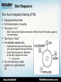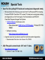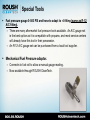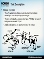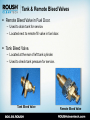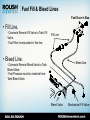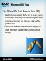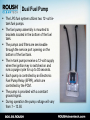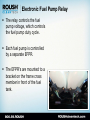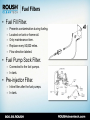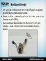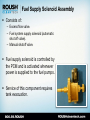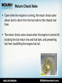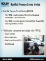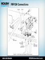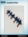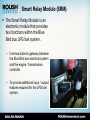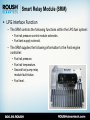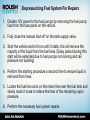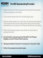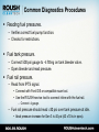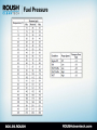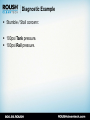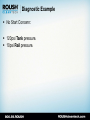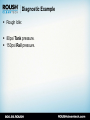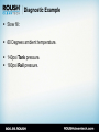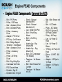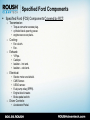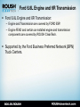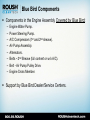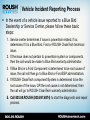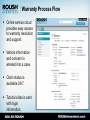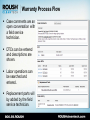
1
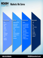
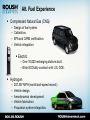
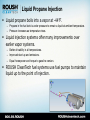
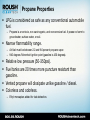
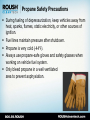
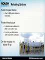
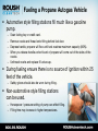
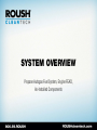
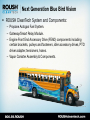
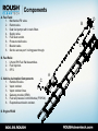
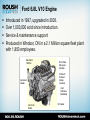
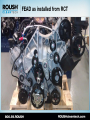
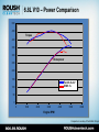
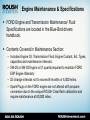
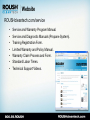
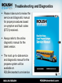
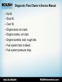
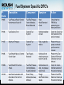
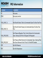
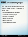
Blue Bird Propane Powered Bus Service & Warranty Support Program Agenda – – – – – – – – Introduction. Propane as an Autogas. ROUSH CleanTech System Overview. Special Tools. Component Overview. Troubleshooting and Diagnostics. Service and Diagnostic Manuals. Service and Warranty Program. ABOUT US Company Background & History Enterprise Brand Portfolio ROUSH Industries OEM manufacturing, engineering, prototyping and design Roush Fenway Racing Dominant NASCAR Sprint Cup racing team ROUSH Performance Industry leading high performance vehicles ROUSH CleanTech Propane autogas powered commercial vehicles. Markets We Serve Transportation Defense Entertainment Motorsports • • • • • • • • • • • • • • • • • • • • • • • • • • • • • • • • • • • • • Ford Chrysler GM Toyota Honda Hyundai Isuzu Volkswagon EcoMotors VPG Navistar Blue Bird Navistar Defense BAE Systems AM General General Dynamics SAIC Textron FAAC US Army/TARDEC Oskosh Defense Hardwire Astradyne • • • • Disney Universal Studios Disneyland Paris Universal Studios Orlando Hong Kong Disneyland Disney California Adventure Universal Studios Singapore The Henry Ford Ford 3M Aflac Crown Royal UPS Scotts Kellogg Valvoline Coca-cola Fastenal Alt. Fuel Experience Compressed Natural Gas (CNG) – – – – Design of fuel system. Calibration. EPA and CARB certification. Vehicle integration. Electric – Over 16,000 recharging stations built. – Blink ECOtality contract with U.S. DOE. Hydrogen – – – – – 207.297 MPH (world land-speed record.) Vehicle design. Aerodynamics development. Vehicle fabrication. Propulsion system integration. Focus on Propane Autogas Technology advancements allow equal performance and range. Fleets see a positive ROI while reducing emissions. ROUSH Enterprises Brand Portfolio ROUSH CleanTech • Dedicated to developing quality alternative fuel solutions. • Propane autogas focus. • EPA and CARB certification capability. • Platform customization to suit customer needs. • Reduces operating costs, carbon footprint. • OEM support through Ford and BPN dealers. • Creating opportunities for partner companies. • Using American fuel and American technology. WHAT IS PROPANE AUTOGAS? Clean. Domestic. Abundant. Safe. Propane as an Autogas High octane fuel with key properties for internal combustion engines. – 3rd most common engine fuel in the world. – 18 million vehicles worldwide. 100 year heritage with automobiles. Lower emissions than gasoline. – – – – Not a greenhouse gas. 24% reduction in Greenhouse Gas (GHG) emissions. 20% reduction in Nitrogen Oxide (NOx) emissions. 60% reduction in Carbon Monoxide (CO) emissions. Domestically produced. – 97% produced in North America. • 73% from natural gas production. – Independence from foreign oil. Infrastructure already in place. 30-40% lower cost than gasoline. Propane Molecule (C3H8) Liquid Propane Injection Liquid propane boils into a vapor at -44°F. – Propane in the fuel tank is under pressure to remain a liquid at ambient temperature. – Pressure increases as temperature rises. Liquid injection systems offer many improvements over earlier vapor systems. – Better drivability in all temperatures. – Improved start up and emissions. – Equal horsepower and torque to gasoline version. ROUSH CleanTech fuel systems use fuel pumps to maintain liquid up to the point of injection. Propane Properties LPG is considered as safe as any conventional automobile fuel. – Propane is a nontoxic, non carcinogenic, and noncorrosive fuel. It poses no harm to groundwater, surface water, or soil. Narrow flammability range. – Air/fuel must be between 2.2 and 9.6 percent propane vapor. – 940 degrees Fahrenheit ignition point (gasoline is 430 degrees). Relative low pressure (50-350psi). Fuel tanks are 20 times more puncture resistant than gasoline. Vented propane will dissipate unlike gasoline / diesel. Colorless and odorless. – Ethyl mercaptan added for leak detection. Propane Safety Precautions During fueling of depressurization, keep vehicles away from heat, sparks, flames, static electricity, or other sources of ignition. Fuel lines maintain pressure after shutdown. Propane is very cold (-44°F). Always use propane-safe gloves and safety glasses when working on vehicle fuel system. Only bleed propane in a well ventilated area to prevent asphyxiation. Refueling Options Public Propane Station – Over 3,000 public stations nationally. Private Infrastructure – Infrastructure available for little to no cost to you. – Lock in your fuel prices with long term contracts. On-site resupply via bobtail fill-up Propane autogas fills at the same rate as gasoline and diesel (approximately 5-7 gallons per minute) Fueling a Propane Autogas Vehicle Automotive style filling stations fill much like a gasoline pump. Scan fueling key or credit card. Remove nozzle and thread onto fitting behind fuel door. Depress handle, propane will flow until tank reaches maximum capacity (80%). When you release handle a short burst of propane will come out of the sides of the nozzle. – Unthread nozzle and replace fill valve cap. – – – – During fueling ensure there is no source of ignition within 25 feet of the vehicle. – Safety gloves should also be worn during filling. Non-automotive style filling stations can be used. – Horsepower / pressure setting of pump can effect filling. – Filling time may increase in higher temperatures. SYSTEM OVERVIEW Propane Autogas Fuel System, Engine FEAD, As-Installed Components Next Generation Blue Bird Vision ROUSH CleanTech System and Components: – Propane Autogas Fuel System. – Gateway/Smart Relay Module. – Engine Front End Accessory Drive (FEAD) components including certain brackets, pulleys and fasteners, idler accessory drives, PTO driver adapter, tensioners, hoses. – Vapor Canister Assembly & Components. Components A. Fuel Tank: 1. Mechanical Fill valve. 2. Return valve. 3. Dual fuel pumps with in-tank filters. 4. Supply valve. 5. Fuel level sender. 6. Pressure relief valve. 7. Bleeder valve. 8. Service access port / wiring pass through. B C B. Fuel Rails: 1. LH and RH Fuel Rail Assemblies. 2. Fuel Injectors. 3. IPTS. C. Vehicle As-Installed Components: C 1. Remote fill valve. 2. Vapor canister. 3. Vapor canister lines. 4. Gateway module (SRM). 5. Fuel rail pressure control Module (FRPCM). 6. Evaporative emission canister. D. Engine FEAD A D C Ford 6.8L V10 Engine Introduced in 1997, upgraded in 2005. Over 1,000,000 sold since introduction. Service & maintenance support. Produced in Windsor, ON in a 2.1 Million square fleet plant with 1,850 employees. Electronic Throttle Two Intake Valves per Cylinder Premium Exhaust Valves (Inconel) Aluminum Heads Cast Stainless Manifolds Cast Iron Block Oil Cooler FEAD as installed from RCT 6.8L V10 – Power Comparison 500 450 Torque 400 350 300 Horsepower 250 200 150 Ford 6.8L-3V GM 8.1L 100 50 0 0 1000 2000 3000 4000 5000 6000 Engine RPM Comparison: courtesy of Ford Motor Compa Engine Maintenance & Specifications FORD Engine and Transmission Maintenance/ Fluid Specifications are located in the Blue-Bird drivers handbook. Contents Covered in Maintenance Section: – Includes Engine Oil, Transmission Fluid, Engine Coolant, Ect. Types, capacities and maintenance intervals. – 5W-20 or 5W-30 Engine oil (7 quarts) required to maintain FORD ESP Engine Warranty – Oil change intervals not to exceed 6 months or 5,000 miles. – Spark Plugs on the FORD engine are not altered with propane conversion due to the unique ROUSH CleanTech calibration and require maintenance at 60,000 miles. Start Sequence One Touch Integrated Starting (OTIS): Engage parking brake. Put transmission in neutral. Turn key to “on.” – Wait 5 seconds (If ignition has been off less than 30 minutes, pause is not necessary.). Turn key to “start.” Immediately release key. – Solenoids will open and fuel pump will cycle propane through the lines. – Once liquid propane is detected at the rails, engine will crank. • 2 - 45 seconds. Do not hold key in start position or cycle back to off. Special Tools Scan Tool (for pulling DTC faults and running basic diagnostic tests). – We recommend the following scan tools from Ford Rotunda SPX for reading Ford and ROUSH CleanTech DTC codes (P Codes) and running basic testing and diagnostics on the Ford engine, Ford transmission and ROUSH CleanTech Propane Autogas Fuel System. • VCM Kit Website (rotunda.spx.com). – Recommended: VCM II kit w/ CFR Pendant -Product ID: 164R9807. • Software Licensing. – http://www.motorcraftservice.com – A generic scan tool can also be used for most fuel system diagnostics. • Recommended: Elite Actron Auto Scanner Pro CP9185. Jiffy-Tite quick connect tools- 3/8” and ¼” sizes. – http://alleganytoolco.com • Call for ¼” size: 716-785-1510. Special Tools Fuel pressure gauge 0-500 PSI and hose to adapt to -4 fitting (same as R-12 A/C fitting). – There are many aftermarket fuel pressure tools available. An A/C gauge set is the best option as it is compatible with propane, and most service centers will already have this tool in their possession. – An R-12 A/C gauge set can be purchased from a local tool supplier. Mechanical Fuel Pressure adaptor. – Connects to fuel rail to allow a manual gauge reading. – Now available through ROUSH CleanTech. COMPONENT OVERVIEW Tank Description Propane Fuel Tank – The LPG fuel system utilizes a dual cylindrical manifold tank assembly to store the liquid propane autogas. – The tank is fitted with a pressure relief valve (PRV) that will open if tank pressure exceeds 312 psi. – ASME certified tanks are rated for the life of the vehicle. Fill Line/ Filter Fill Valve Fuel Supply/Return Lines Bleeder Valve Sending Unit Pressure Relief Tube Fuel Tank – Top Service Access Port/ Wiring Pass-through Fuel Tank - Bottom Mechanical Fill Valve Tank & Remote Bleed Valves Remote Bleed Valve in Fuel Door. – Used to drain tank for service. – Located next to remote fill valve in fuel door. Tank Bleed Valve. – Located at the rear of left tank cylinder. – Used to check tank pressure for service. Tank Bleed Valve Remote Bleed Valve Fuel Fill & Bleed Lines Fuel Door in Bus • Fill Line. -Connects Remote Fill Valve to Tank Fill Valve. -Fuel Filter incorporated in this line. Fill Line • Bleed Line. Bleed Line -Connects Remote Bleed Valve to Tank Bleed Valve. -Fuel Pressure must be checked from Tank Bleed Valve. Bleed Valve Mechanical Fill Valve Mechanical Fill Valve Tank Fill Valve / 80% Overfill Prevention Device (OPD). – Located where fuel enters into the fuel tank, the fill valve is opened mechanically by the refueling pump pressure during the fill process. – It also incorporates a back flow check valve and an overfilling prevention device. – The back flow check valve closes when vehicle tank pressure is greater than pressure outside of the tank to prevent fuel from escaping. Dual Fuel Pump The LPG fuel system utilizes two 12-volt intank fuel pumps. The fuel pump assembly is mounted to brackets located in the bottom of the fuel tank. The pumps and filters are serviceable through the service port opening on the bottom of the fuel tank. The in-tank pumps receive a 12-volt supply when the ignition key is switched on and runs a purge cycle for up to 30 seconds. Each pump is controlled by an Electronic Fuel Pump Relay (EFPR), which are controlled by the PCM. The pump is provided with a constant ground signal. During operation the pump voltage will vary from 7 – 13.5V. Electronic Fuel Pump Relay The relay controls the fuel pump voltage, which controls the fuel pump duty cycle. Each fuel pump is controlled by a separate EFPR. The EFPR’s are mounted to a bracket on the frame cross member in front of the fuel tank. Fuel Filters • Fuel Fill Filter. – – – – – Prevents contamination during fueling. Located on tank or frame rail. Only maintenance item. Replace every 50,000 miles. Flow direction labeled. • Fuel Pump Sock Filter. – Connected to the fuel pumps. – In tank. • Pre-injector Filter. – Inline filter after the fuel pumps. – In tank. Fuel Level Sender The fuel level sender consists of an in-tank float arm coupled to an externally mounted variable resistor. Sender provides a fuel level signal to the instrument panel via the Gateway Module (SRM). Fuel level sender is serviceable from the top of the tank and includes a visual indicator which can be referenced during service. Fuel Supply Solenoid Assembly Consists of: – Excess flow valve. – Fuel system supply solenoid (automatic shut off valve). – Manual shutoff valve. Fuel supply solenoid is controlled by the PCM and is activated whenever power is supplied to the fuel pumps. Service of this component requires tank evacuation. Return Check Valve Open when the engine is running, the return check valve allows fuel to return from the fuel rails to the chassis fuel lines. The return check valve closes when the engine is turned off, isolating the fuel return line and fuel tank, and preventing fuel from backfilling the engine fuel rail. Fuel Rail Pressure Control Module Fuel Rail Pressure Control Module (FRPCM). – The FRPCM is a unit consisting of three (3) normally closed solenoids and a return check valve. – The FRPCM is controlled directly by the Smart Relay Module (SRM) which is governed by the PCM. The following components are included in the FRPCM: – – – – Supply Solenoid. Return Check Valve. Flow Control Solenoid (FCS). Bleed Solenoid. FRPCM Connections Supply Solenoid Open (energized) when the engine is running, the supply solenoid allows fuel to flow from the chassis fuel lines to the fuel rail. The supply solenoid is closed when the engine is turned off, preventing fuel from flowing from the chassis fuel lines to the engine fuel rail. Note: There is a second supply solenoid located at the fuel tank which prevents fuel from flowing into the chassis fuel lines when the engine is turned off. Flow Control Solenoid (FCS) The flow control solenoid is located in the FRPCM return flow circuit. During normal engine operation the solenoid is closed. This directs the fuel flow through a metered orifice; this results in increased pressure at the fuel rail (similar to a conventional pressure regulator). Prior to and immediately following engine start and in extremely hot fuel conditions, the FCS opens, which opens a bypass flow circuit around the metered orifice, increasing fuel flow through the rail. Bleed Solenoid Closed when the engine is running, the bleed solenoid seals the fuel rail from the vehicle EVAP system. After the engine is turned off for approximately one hour, the bleed solenoid opens for a calibrated length of time allowing all the fuel pressure to bleed from the fuel rail through a metered orifice and into the carbon canister. When fuel pressure is fully bled off, the solenoid closes, preventing fuel from entering the EVAP system. Evaporative Emissions Canister Vapor Canister Assembly – A vapor canister is being utilized to vent the fuel vapors remaining in the fuel rail during engine shut-off to eliminate the chance of propane leaking past the fuel injectors. – This also improves vehicle emissions and overall starting performance. Vapor Lines – The fuel vapor hoses are flexible and quick connect fittings, which can be easily disconnected by pinching the connector release points. Fuel Rail Assembly Each fuel rail assembly is mounted to the intake manifold by three (3) brackets, and is made up of the following components: – Five (5) fuel injectors retained in the fuel rail by a C-clip. The injectors are connected to the main engine wiring harness. Injectors are opened and closed by switching the ground internally in the PCM. – Five (5) injector spacers sealed to the fuel rail and intake manifold injector ports by orings and retained to the fuel rail with a retention clip. – Two (2) quick connect fittings at the end of the rails connect the supply and return hoses to the fuel rail assemblies. – An Injection Pressure and Temperature Sensor (IPTS) is mounted on the left hand rail. Assembled Fuel Rails Smart Relay Module (SRM) The Smart Relay Module is an electronic module that provides two functions within the Blue Bird bus LPG fuel system. – Communications gateway between the Blue Bird bus electrical system and the engine / transmission controller. – To provide additional input / output features required for the LPG fuel system. Smart Relay Module (SRM) Gateway Function – The SRM provides the following signals to the Blue Bird bus from the Ford engine / transmission module: • • • • • Engine data. Transmission data. Start in progress. Fuel level. Diagnostic warning light requests. – The SRM reads the following signals from the Blue Bird bus and reports them to the engine controller: • • • • • Front AC request. Rear AC request. Cruise control switch positions. Throttle interlock requests. High idle speed request. Smart Relay Module (SRM) LPG Interface Function – The SRM controls the following functions within the LPG fuel system: • Fuel rail pressure control module solenoids. • Fuel tank supply solenoid. – The SRM supplies the following information to the Ford engine controller: • Fuel rail pressure. • Fuel rail temperature. • Second fuel pump relay module fault status. • Fuel level. TROUBLESHOOTING AND DIAGNOSTICS OVERVIEW Website ROUSHcleantech.com/service • • • • • • • Service and Warranty Program Manual. Service and Diagnostic Manuals (Propane System). Training Registration Form. Limited Warranty and Policy Manual. Warranty Claim Process and Form. Standard Labor Times. Technical Support Videos. Troubleshooting and Diagnostics Please make sure to review the service and diagnostic manual for proper procedures based on symptom and fault codes (DTC’s) received. Always refer to the online diagnostic manual for the latest version. The most up-to-date service and diagnostic manual for the propane system will be available on ROUSHcleantech.com/service Diagnostic Flow Charts in Service Manual – – – – – – – – No fill. Slow fill. Over fill. Engine does not crank. Engine cranks, not start. Engine stumble, stall, rough idle. Fuel system fails to bleed. Fuel system pressure drop. Depressurizing Fuel System For Repairs 1. Disable 12V power to the fuel pumps by removing the fuel pump fuse from the fuse panel on the vehicle. 2. Fully close the manual shut-off on the tank supply valve. 3. Start the vehicle and let it run until it stalls, this will remove the majority of the liquid from the fuel lines. (Delay period during this start will be extended due to fuel pumps not running and rail pressure not building) 4. Perform the starting procedure a second time to ensure liquid is removed from lines. 5. Locate the fuel line union on the return line near the fuel tank and slowly crack it loose to relieve the lines of the remaining vapor pressure. 6. Perform the necessary fuel system repairs. Ford IDS Depressurizing Procedure 1. Disable 12V power to the fuel pumps by removing the fuel pump fuse from the fuse panel on the vehicle. 2. Fully close the manual shut-off on the tank supply valve. 3. Start the vehicle and let it run until it stalls, this will remove the majority of the liquid from the fuel lines. (Delay period during this start will be extended due to fuel pumps not running and rail pressure not building) 4. Perform the starting procedure a second time to ensure liquid is removed from lines. 5. Using Ford IDS, command open Fuel Shutoff B, Fuel Pressure Regulator, and Fuel Pressure Relief solenoids. 6. Wait approximately 20 minutes for fuel pressure to drop below 10psi. 7. Perform the necessary fuel system repairs. Common Diagnostics Procedures Reading fuel pressures. – Verifies correct fuel pump function. – Checks for restrictions. Fuel tank pressure. – Connect 500 psi gauge to -4 fitting on tank bleeder valve. – Open bleeder and read pressure. Fuel rail pressure. – Read from IPTS signal. • Connect with Ford IDS or compatible scan tool. • Use the ROUSH service tool to connect inline with the fuel rail. – Connect -4 gauge. – Fuel rail pressure should read >30 psi over tank pressure at idle. • Ideal pressure increase for Gen 3 is 40 psi (40 ±10 is in spec). Fuel Pressure Diagnostic Example Stumble / Stall concern: 100psi Tank pressure. 100psi Rail pressure. Diagnostic Example No Start Concern: 120psi Tank pressure. 10psi Rail pressure. Diagnostic Example Rough Idle: 80psi Tank pressure. 150psi Rail pressure. Diagnostic Example Slow fill: 60 Degrees ambient temperature. 140psi Tank pressure. 180psi Rail pressure. Fuel System Specific DTC’s PCode Description Component Symptom Action P009E Fuel Pressure Relief Control Performance Stuck Off Fuel Rail Pressure Control ModuleBleed Solenoid Hard Start/Extended Crank Check that the FRPCM is performing the bleed procedure. P0148 Fuel Delivery Error General Fuel System Vehicle hesitation or stall. Go to the Crank, No Start section of the service manual. P116E Maximum Pressure General Fuel System Stall, rough idle, misfire Perform the fuel pressure checks per the service manual. P0005 Fuel Shutoff Valve A Control Circuit Open Tank Supply Solenoid Vehicle will not start/no pressure build in fuel rail. Perform the Tank Solenoid Electrical Check per service Manual. P26B5 Fuel Shutoff B Function Check Fuel Rail Pressure Control ModuleSupply Solenoid Vehicle does not start, no pressure build in rail. Go to the Crank, No Start section of the service manual. U0108 Lost Communication with Alternative Fuel Control Module. Smart Relay Module (Gateway Module) Rough Idle/Performance Issues Perform the SRM Electrical Check per the service manual. PID Information Acronym Description FP Fuel pump FPM Fuel pump monitor FUEL_SHUT_A Fuel Shutoff Valve A Tank Is Commanded Open To Allow Fuel Flow FUEL_SHUT_B Fuel Shutoff Valve B Supply Is Commanded Open To Allow Fuel Flow FUEL_PRS_REG Fuel Pressure Regulator Flow Control Solenoid Is Commanded Open, Allowing Fuel Flow To Bypass The Regulator FUEL_PRS_RLF Fuel Pressure Relief Solenoid Is Commanded Open, Allowing Post Shut Down Remnant Fuel To Flow To The EVAP Canister FRP Fuel Rail Pressure FRT Fuel Rail Temperature SERVICE AND WARRANTY PROGRAM Basic Coverage and Training Service and Warranty Program The ROUSH CleanTech Service Program for Blue Bird consists of multiple components to assist Dealers and Service Centers: – – – – – – Service Center Agreement (Basic Requirements). Interactive Web-Based Training Program. Service and Diagnostic Manuals. Technical Information Videos. Technical Phone Support. Warranty Claims Resolution Process. Authorized Service Center Network Please see the Dealer Locator at ROUSHcleantech.com for an interactive map of current Authorized Service Centers. – Includes a filter for Blue Bird Service Centers, including Blue Bird Dealers and Ford BPN Truck Centers supporting Blue Bird. Service Parts Support Service parts (outside of warranty) will only be available through the Blue Bird Service Organization to Blue Bird Dealers and Service Centers. Limited Warranty Description Basic Description of Coverage (as listed in the Limited Warranty Statement): – On the Blue Bird Propane-Powered Vision Bus, ROUSH CleanTech will cover the propane autogas fuel system, specified engine FEAD components and Ford components for 5 years or 100,000 miles, whichever comes first, as defined in the RCT Warranty Statement and the RCT Warranty and Policy Manual. ROUSH CleanTech Components ROUSH CleanTech System and Covered Components: – Propane Autogas Fuel System. – Gateway/Smart Relay Module. – Engine Front End Accessory Drive (FEAD) components including certain brackets, pulleys and fasteners, idler accessory drives, PTO driver adapter, tensioners, hoses. – Vapor Canister Assembly & Components. – Specified Ford supplied components. Support by Blue Bird Dealer/Service Centers, Ford Business Preferred Network (BPN) Truck Centers and other Service Centers in the RCT Network. Engine FEAD Components • Engine FEAD Components Covered by RCT: – – – – – – – – – – – – – – – – – Brkt - P/S Pump Pulley - P/S Pump Idler - Accessory Drive Brkt - Alt Delete Pulley Pulley - Accessory Drive Adapter - PTO Driver PTO Asy - 2nd Sheave Brkt - Bridge Support Tensioner - 2nd sheave Idler - Accessory Drive Pulley - Accessory Drive Pulley - Air Pump Driver Brkt - Eng Lifting Eye Crankcase Vent Tube PCV Closure Hose Dipstick - Eng Oil Dipstick Tube - Eng Oil – Shield - Exhaust Manifold (RH) – Shield - Exhaust Manifold (LH) – Cap - Water Inlet Port – Brkt - RH off Eng Mount – Brkt - LH off Eng Mount – Isolator Asy - Eng Mount (RH) – Isolator Asy - Eng Mount (LH) – Brkt - A/C Compressor (1st Sheave) – Tensioner - 1st Sheave w/ AC – Belt - Main Sheave Full Content – Tensioner - 1st Sheave w/o AC – Belt - Main Sheave w/o A/C – Brkt - A/C Delete – Pulley - A/C Delete – FEAD Kit Option #3… Air Pump Content – Pulley - Air Pump – Line - Air Pump Oil Feed – Line - Air Pump Oil Return – T-Fitting - Air Pump Oil Feed – Elbow - 1/2 NPT - 5/8 Tube – Adaptor - 1/8 Pipe to 1/4 Tube – Adaptor - 1/4 Pipe to 1/4 Tube Specified Ford Components Specified Ford (FCS) Components Covered by RCT: – Transmission: • Torque converter access plug. • cylinder block opening cover. • engine rear cover plate.. – Cooling: • Fan clutch. • Fan. – Exhaust: • • • • Y-Pipe. Catalyst. Isolator – hot end. Isolator – cold end. – Electrical: • • • • • • Starter motor and shield. CMS Sensor. UEGO sensor. Fuel pump relay (EFPR). Engine block heater. Brake pedal switch. – Driver Controls: • Accelerator Pedal. Ford 6.8L Engine and 6R Transmission Ford 6.8L Engine and 6R Transmission: – Engine and Transmission are covered by FORD ESP. – Engine FEAD and certain as-installed engine and transmission components are covered by ROUSH CleanTech. Supported by the Ford Business Preferred Network (BPN) Truck Centers. Blue Bird Components Components in the Engine Assembly Covered by Blue Bird: – – – – – – – – Engine Water Pump. Power Steering Pump. A/C Compressors (1st and 2nd sheave). Air Pump Assembly. Alternators. Belts – 2nd Sheave (full content or w/o A/C). Belt - Air Pump Pulley Drive. Engine Cross Member. Support by Blue Bird Dealer/Service Centers. Vehicle Incident Reporting Process In the event of a vehicle issue reported to a Blue Bird Dealership or Service Center, please follow these basic steps: 1. Service center determines if issue is powertrain related, if so, determines if it is a Blue Bird, Ford or ROUSH CleanTech technical issue. 2. If the issue does not pertain to powertrain system or components, then the call would be made to Blue Bird warranty administrator. 3. If Blue Bird or a Ford Component is determined to be root cause of issue, the call will then go to Blue Bird or Ford ESP administrators. 4. If ROUSH CleanTech component/System is determined to be the root cause of the issue, OR the root cause is not determined, then the call will go to ROUSH CleanTech warranty administrator. 5. Call 800.59.ROUSH (800.597.6874) to start the diagnostic and repair process. Warranty Process Flow Online service cloud provides easy access to warranty resolution and support. Vehicle information and concern is entered into a case. Claim status is available 24/7. Tutorial video is sent with login information. Warranty Process Flow Case comments are an open conversation with a field service technician. DTCs can be entered and descriptions are shown. Labor operations can be searched and entered. Replacement parts will by added by the field service technician. CONTACT US: 800.59.ROUSH (Option 2) ROUSHcleantech.com Technical Hotline Warranty Fax Line 734.779.7777 1.800.59.ROUSH(Opt 2) 734.779.7700 [email protected]