1
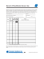
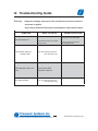
HD02 Repair & Maintenance Manual
Transonic
Transonic®
Flow
Q C
®
Quality Care
HD02
Hemodilaysis Monitor
THE INFORMATION HEREIN IS PROPRIETARY.
NO PART OF IT MAY BE COPIED OR DISTRIBUTED
WITHOUT EXPRESS WRITTEN PERMISSION
OF
TRANSONIC SYSTEMS INC. MANAGEMENT.
USA Technical Support
Call # 1-800-353-3569 (USA)
AUSHD02 Service Manual
Rev. B, 3/04
Copyright 2003 by Transonic Systems Inc.
Transonic Systems Inc.
Tel: 800-353-3569(USA); Fax 607- 257-7256; www.transonic.com
Europe: Tel: 31 43 407 7200; e-mail: [email protected]; Fax: 3143 407 7201
HD02 Maintenance & Repair Manual
Contents
I.
INTRODUCTION
page
a. Scope of Manual . . . . . . . . . . . . . . . . . . . . . . . . . . . . . . . . . . . . . . . . . . 1
b. Factory Guarantee . . . . . . . . . . . . . . . . . . . . . . . . . . . . . . . . . . . . . . . . . 2
c. Equipment Return Instructions . . . . . . . . . . . . . . . . . . . . . . . . . . . . . . . . 3
II.
PERIODIC MAINTENANCE REQUIREMENTS
a. Monitor . . . . . . . . . . . . . . . . . . . . . . . . . . . . . . . . . . . . . . . . . . . . . . . . . . 4
b. Flowsensors . . . . . . . . . . . . . . . . . . . . . . . . . . . . . . . . . . . . . . . . . . . . . . 4
c. Record of Sterile Tubing Flowsensor Use . . . . . . . . . . . . . . . . . . . . . . . . 5
III. FLOW MONITOR SPECIFICATIONS . . . . . . . . . . . . . . . . . . . . . . . . . . . 6
IV. TROUBLESHOOTING GUIDE
a. Guide . . . . . . . . . . . . . . . . . . . . . . . . . . . . . . . . . . . . . . . . . . . . . . . . . . . 7
b. Replacement Parts . . . . . . . . . . . . . . . . . . . . . . . . . . . . . . . . . . . . . . . . . 8
V. CIRCUIT OPERATION & BLOCK DIAGRAM
a. Theory of Operation . . . . . . . . . . . . . . . . . . . . . . . . . . . . . . . . . . . . . . . . 9
b. Circuit Operation & Block Diagrams . . . . . . . . . . . . . . . . . . . . . . . . . . . 11
Transonic Systems Inc.
Tel: 800-353-3569(USA); Fax 607- 257-7256; www.transonic.com
Europe: Tel: 31 43 407 7200; e-mail: [email protected]; Fax: 3143 407 7201
AUSHD02 Service Manual page i
I-a. Introduction
1-a: SCOPE OF THIS MANUAL
The intent of this service manual is to teach flowmeter Users and their Biomedical
Engineering Service Departments how to maintain HD02 flowmonitor and flowsensor for
performance to factory specifications, and how to make elementary repairs, if necessary.
Physical care of the flowmeter and flowsensor, including sterilization and cleaning
procedures, is also described in the Operator’s Manual. In any instance of equipment
malfunction, the User is asked to return the equipment to Transonic Systems Inc. or to its
authorized agents for repair or recalibration.
CAUTION: SERVICE BY NON-AUTHORIZED PERSONNEL WILL VOID
THE FACTORY WARRANTY AND MAY VOID THE SAFETY RATING.
Transonic Systems Inc. offers a liberal factory warranty on its flowmeters and flowsensors
(see next page). In no event, should the User attempt to modify the flowmeter or flowsensor.
Transonic Systems Inc.
Tel: 800-353-3569(USA); Fax 607- 257-7256; www.transonic.com
Europe: Tel: 31 43 407 7200; e-mail: [email protected]; Fax: 3143 407 7201
AUSHD02 Service Manual page 1
I-b. Factory Guarantee, Service & Warranty
A.
CALIBRATION GUARANTEE
Transonic Systems Inc. certifies that HD02 Hemodialysis Monitor and its software are calibrated by
methods traceable to the USA National Institute of Standards and Technology (“NIST”). Transonic Systems
Inc. guarantees that the HD02 Flowmeter will stay in calibration during its first year of use, if used and
stored per standard clinical apparatus practices. Product users may purchase additional years of
recalibration service and certification.
B.
LIMITED WARRANTY
Transonic Systems Inc. warrants for a period of one (1) year from the date of shipment that HD02
Hemodialysis Monitor will remain free from defects which are the result of faulty material or workmanship.
Product users may purchase additional years of warranty and repair service insurance. Transonic Systems
Inc. warranty shall not apply to: a. defects caused by abuse, neglect or misuse; (e.g., cut cable, pulled cable
broken sensor body due to mishandling); b. damage due to accident or casualty; or c. unauthorized repairs,
alterations. Transonic Systems Inc. warrants for a period of one (1) year from the date of shipment that H4E
sterile tubing sensor will remain free from defects which are the result of faulty material or workmanship.
Transonic Systems Inc. will, at no cost to the user, either repair or replace a monitor or sensor found
defective within its warranty period. The Buyer pays shipping charges.
No other warranty is expressed or implied. Transonic Systems Inc. is not liable for incidental or
consequential damages. Warranty is valid only if equipment is purchased through Transonic Systems or
its duly appointed distributor or licensed representative.
C.
WARRANTY CLAIM
The obligations of Transonic Systems Inc. under this warranty are limited to repairing or, at its option,
replacing any goods determined to be defective. Buyer must notify Transonic Systems Inc. in writing within
the warranty period of the reason Buyer believes that warranty repairs are required. Buyer is then required
upon the request of Transonic Systems Inc. and at Buyer's expense, to return the goods to the Transonic
Systems Inc. manufacturing plant. Freight for shipping the repaired goods from the Transonic Systems Inc.
manufacturing plant to Buyer's place of business shall be paid for by the Buyer. Any goods repaired or
replaced by Transonic Systems Inc. shall be warranted for the period of time remaining on the original
warranty from its date of inception.
Transonic Systems Inc.
Tel: 800-353-3569(USA); Fax 607- 257-7256; www.transonic.com
Europe: Tel: 31 43 407 7200; e-mail: [email protected]; Fax: 3143 407 7201
AUSHD02 Service Manual page 2
I-c. Equipment Return Instructions
A.
METERS
1.
Call Transonic Systems Customer Service (1-800-353-3569) with a description of the problem and the
Service Technician will give you a RMA (return material authorization) number.
2.
Please use the shipping carton supplied with the meter for returning the meter for repair.If you need a
carton, contact Customer Service at 1-800-353-3569.
3.
Place the two foam packing pieces over the front and back ends of the flowmeter to protect the meter
from damage. Notches in the foam should correspond to the cable exiting the front of the meter.
4.
Lift the instrument with its foam padding into the box.
5.
On top of the foam, place the cardboard insert along with all correspondence, cables, manuals etc.
Seal the box for shipping.
6.
With a carrier of your choice, ship the meter back to the factory. The address is:
Transonic Systems Inc.
34 Dutch Mill Road.
Ithaca, NY 14850, USA
7.
B.
Direct all questions to Customer Service at @ 800-353-3569 (USA) or fax us @ 607-257- 7256.
REUSABLE FLOWSENSORS/PROBES
1.
Call Customer Service (1-800-353-3569USA) with a description of the problem and the Service
Technician will give you a RMA (return material authorization) number.
2.
Thoroughly clean all sensors. Any sensor that has not been cleaned will be immediately returned
without repair.
3.
Package all parts of the flowsensor in the original packaging along with any correspondence you wish
to include.
4.
With a carrier of your choice, ship the meter back to the factory. The address is:
Transonic Systems Inc.
34 Dutch Mill Road.
Ithaca, NY 14850, USA
7.
Direct all questions to Customer Service at @ 800-353-3569 (USA) or fax us @ 607-257- 7256.
Transonic Systems Inc.
Tel: 800-353-3569(USA); Fax 607- 257-7256; www.transonic.com
Europe: Tel: 31 43 407 7200; e-mail: [email protected]; Fax: 3143 407 7201
AUSHD02 Service Manual page 3
II. Periodic Maintenance Requirements
II-a
MONITOR
Maintenance Check: A routine maintenance check of the meter consists of exercising all of the
functions of the meter with a sampling of flowsensors, and verifying that all features respond as
described in the “Functional Tests” section of the Operator’s Manual. If any of these functions do not
respond as described, contact Transonic Systems Technical Support Service (1-800-353-3569 USA).
Cleaning: Exterior flowmeter surfaces can be cleaned using a cloth or brush dampened with soapy
water, followed by damp wiping with clear water. Alternately, the surface can be damp-wiped clean
with isopropyl alcohol at room temperature in a dry place. Warning - Do not drip liquids into the meter
cabinet. A flowmeter accidently exposed to spillage should be immediately unplugged from its power
source. Remove the cover. If the spilled liquid is potentially corrosive or may leave a residue, flood the
area with clean water, using care not to disturb components or components. Compressed air may be
used to blow liquid off components. Remove the remaining liquid from the unit with a heat gun or a
hair dryer. Do not operate the flowmeter in a wet condition. Extreme damage may occur to the
unit.
II-b
FLOW/DILUTION SENSORS
Flow/Dilution Sensors: After use of a sterile tubing flowsensor, wash and sterilize the sensor
according to the instructions in the Operator’s Manual. If the connector becomes wet, drying overnight
in an incubator oven (≤60ºC, 140ºF) is recommended. Transcribe the flow data to the Record of
Sensor/Probe Use available in this manual, along with observations of the sensor’s received quality
strength. Signal quality usually diminishes as the sensor increases in age. If the received signal quality
drops below the 50% level, the sensor should not be used. Inspect the cables and connectors
routinely for damage. Store the sensors at room temperature.
Transonic Systems Inc.
Tel: 800-353-3569(USA); Fax 607- 257-7256; www.transonic.com
Europe: Tel: 31 43 407 7200; e-mail: [email protected]; Fax: 3143 407 7201
AUSHD02 Repair Manual, page 4
Record of Flow/Dilution Sensor Use
Maintaining a record of sensor received signal quality is part of routine sensor maintenance. The sensor's received
signal is normalized to 1.0 at the factory on the tubing for which the sensor is built and should vary only slowly over
time (due to transducer “aging”) when the sensor is used with the tubing specified on its Transonic Flowsensor
Specifications sheet. As signal degradation may indicate improper mounting of the sensor or deterioration of sensor
function, performance tracking is helpful in diagnosing problems before flow readings become questionable.
User/contact person _________________________________
phone # _____________________
Sterile-tubing (clamp-on) probe # _____________________
date received ________________
Made for tubing material ______________________________
O.D. ___________ I.D. _________
Date
Example
Rec’d
Signal
Amplitude
12/9/97
√ How Used
Bench
good*
In Patient
Circuit
Notes
(Describe tubing if different)
✔
* Good = Signal Quality indicator on meter’s front panel is fully lit.
Bench-test procedures are described Section C of this manual. When returning sensors for factory examination, call
the factory beforehand for a Return Material Authorization (RMA) number and include this page along with the
sensor.
Transonic Systems Inc.
Tel: 800-353-3569(USA); Fax 607- 257-7256; www.transonic.com
Europe: Tel: 31 43 407 7200; e-mail: [email protected]; Fax: 3143 407 7201
AUSHD02 Service Manual page 5
III. HD02 Flow Monitor Specifications
HD02 FLOW MONITOR - Ultrasonic transit-time volume flowmeters
•
•
Weight - 10 lbs.
Case size 11” wide x 14 “ deep x 4” high (27.8 cm x 35.4 cm x 9.12 cm)
General Features
•
•
•
•
•
Automatic sensor recognition and re-scaling of the meter.
USB Port
High visibility red LED display.
Convenient ground connection on rear of unit.
Pull cart mounting system available for system mobility.
General Specifications
•
•
•
•
•
•
Input power - 100-249 VAC 50-60 HZ
Detachable medical grade grounded power cord.
Fuses - 2 each 1.5A fast-blo 250 VAC 5 x 20 mm.
Patient electrical isolation - IEC601 - 1 defibrillation proof @ 5000V.
USB Port
Agency listed with ETL, CSA, IEC601-1, MDD and CE mark tested and approved.
Transonic Systems Inc.
Tel: 800-353-3569(USA); Fax 607- 257-7256; www.transonic.com
Europe: Tel: 31 43 407 7200; e-mail: [email protected]; Fax: 3143 407 7201
AUSHD02 Service Manual page 6
IV. Troubleshooting Guide
Warning:
Dangerous voltages are present in the unit when the covers are removed
and power is applied.
Only Factory Authorized Personnel are permitted to work inside the meter.
SYMPTOM
WHAT TO CHECK
Check the AC power cord
Unit will not turn on.
The monitor does not
measure flow
Check the AC fuses in the power
entry module
CORRECTIVE ACTION
Ensure that all power cord
connections are fulled seated
If blown, replace the TSI P/N
TF1A5M5X20 fuses
Call Technical Support Service
1-800-353-3569 (USA)
HD02 Aquisition does not
work
Consult the HD02
Operator’s Manual
Any other problem
Call Technical Support Service
1-800-353-3569 (USA)
Transonic Systems Inc.
Tel: 800-353-3569(USA); Fax 607- 257-7256; www.transonic.com
Europe: Tel: 31 43 407 7200; e-mail: [email protected]; Fax: 3143 407 7201
AUSHD02 Service Manual page 7
IV. Replacement Parts
DESCRIPTION
1.
2.
3.
4.
5.
6.
7.
8.
9.
10.
11.
12.
TRANSONIC SYSTEMS INC. P/N
Sensor holder, HD02
Fuse 1.5A 240 VAC 5mm x 20 mm
AC power cord, medical grade, US
AC power cord, medical grade, Europe
AC power cord, medical grade, UK
AC power cord, medical grade, Australia
Operator’s Manual, HD02
Standard rolling stand
Laptop compatible rolling stand
HD02 computer monitor software
USB Cable
USB Upgrade Kit
FEF1003
TF1A5MX20
TPC101-H
TPC101-EUR
TPC101-UK
TPC101-AUS
AUTHD02
AOS1000
AOS1002
ASCDHD02
AEUSB-2
AMUSBK-1
Transonic Systems Inc.
Tel: 800-353-3569(USA); Fax 607- 257-7256; www.transonic.com
Europe: Tel: 31 43 407 7200; e-mail: [email protected]; Fax: 3143 407 7201
AUSHD02 Service Manual page 8
V. Ultrasound Dilution Theory of Operation
HD-Series Monitors Use Ultrasound
Transit-time Technology to Measure
Principle I:
Differential Transit-Time
Ultrasound
Delivered Blood Flow
Delivered Blood Flow (flow in the dialysis tubing, pump
flow): Ultrasound sensors clipped onto hemodialysis
tubing blood lines transmit minute levels of ultrasound
through the tubing wall into the blood stream. Sensitive
electronics derive flow via transit-time ultrasound
principles.
Access Flow: After reversing the blood lines, the
sensors measure Access Flow by the patented
Krivitski Method®.
Cardiac Output: With blood lines in their normal
position, the Transonic monitor analyzes cardiopulmonary recirculation (CPR) to measure cardiac
output.
During hemodialysis two matched flow/dilution sensors
are clipped onto the arterial and venous dialysis lines
(Fig 1). The monitor continuously displays delivered
blood flow. Comparison of this reading with the pump
flow setting (i.e., the flow the pump tries to deliver) provides
an opportunity to identify and correct dialysis delivery
problems.
HDXX
Hemodialysis
Monitor
A
Principle II:
b)
Patient
Dialyzer
V
Cable
Dialysis Tubing
The clip-on sensor transmits a beam
of ultrasound through the blood line.
Two transducers pass ultrasonic
Fig. 2: Clip-on
signals back and forth, alternately
Flow/Dilution Sensor
intersecting the flowing blood in
upstream and downstream directions. The
Hemodialysis Monitor derives an accurate measure of
the changes in "transit time" (time it takes for the wave of
ultrasound to travel from one transducer to the other) resulting
from the motion of the blood in the vessel.
The difference between the upstream and downstream
transit times is a measure of volume flow.
Access Recirculation: Using indicator dilution
principles, the same sensors sense the direct reflux of
saline from the venous line back into the arterial line
after a saline indicator change in the venous blood line.
Transonic
Flow/Dilution
Sensor
d)
Fig. 1: Transit-time flow/dilution sensing during hemodialysis.
System Components
a) Hemodialysis Monitor
b) Transonic Arterial & Venous Flow/Dilutions
Sensors
c) Laptop computer for automated calculations
d) Isotonic saline (0.9% NaCl) released from the
patient’s saline bag or by direct injection into
the blood line.
Ultrasound Indicator Dilution
Patient Blood Flows & Recirculation
The velocity of ultrasound in blood (1560-1590 m/sec) is
determined primarily by its blood protein concentration.
The Transonic® Hemodialysis Monitor and clip-on
Flow/dilution Sensors measure ultrasound velocity. A
bolus of isotonic saline (ultrasound velocity: 1533 m/sec)
introduced into the blood stream dilutes the blood and
reduces the ultrasound velocity. The sensor records
this saline bolus as a conventional indicator dilution
curve.
A bolus of saline indicator is introduced into the blood
line. As the saline passes through the blood lines, the
arterial and venous sensors each register an indicator
dilution curve. The following measurements can be
selected:
Protected under USA patents # 5,453,576; 5,595,182; 5,685,989.
International patent #EP 0 781 161 B1
Transonic Systems Inc.
Tel: 800-353-3569(USA); Fax 607- 257-7256; www.transonic.com
Europe: Tel: 31 43 407 7200; e-mail: [email protected]; Fax: 3143 407 7201
AUSHD02 Service Manual page 9
V. Ultrasound Dilution Theory of Operation
Principle II: Ultrasound Indicator Dilution cont.
Access Recirculation: the Hemodialysis Monitor
identifies the direct reflux of the venous saline indicator
bolus into the arterial line (Fig. 3). The ratio of indicator
concentrations equals access recirculation. High timing
resolution enables identification of zero access
recirculation (Fig. 3).
Fig. 5: Typical induced recirculation curves for the
Krivitski Method®for calculating Qa.
Fig. 3: Typical forward-line indicator concentration
curves showing 0% access recirculation.
Ó
Access Flow is measured by the The Krivitski Method®,
a pioneering Transonic® contribution to vascular access
management (Fig. 4). The upstream (venous) access
needle
introduces an indicator into the access flow stream.
The downstream (arterial) access needle samples the
blood concentration diluted by the indicator (Figs. 5).
Venous
Line
Isotonic saline
introduction
Cardiac Output: with blood lines in the normal
configuration and no direct recirculation present,
cardiopulmonary recirculation provides a measure
of cardiac output (Fig. 6). The full saline indicator
bolus travels into the heart where it is mixed (diluted)
into the full cardiac output. Part of this diluted
indicator then reappears at the Transonic® arterial
sensor. Cardiac output and Cardiac Index are
calculated via conventional Stewart-Hamilton
analysis.
Arterial
Line
Flow/
dilution
Sensors
Needle
Mixing area
Qa
Fig. 6: Typical forward-line indicator concentration
curves cardiac output.
Needle
Q*a
Access Flow
Fig. 4: Krivitski Method: Access Flow Measurement.
Dialysis lines are reversed to induce recirculation
from which vascular access flow (Qa) is
calculated.
Transonic Systems Inc.
Tel: 800-353-3569(USA); Fax 607- 257-7256; www.transonic.com
Europe: Tel: 31 43 407 7200; e-mail: [email protected]; Fax: 3143 407 7201
AUSHD02 Service Manual page 10
V. Circuit Operation & Block Diagram
Transonic Systems Inc.
Tel: 800-353-3569(USA); Fax 607- 257-7256; www.transonic.com
Europe: Tel: 31 43 407 7200; e-mail: [email protected]; Fax: 3143 407 7201
AUSHD02 Service Manual page 11
V. Circuit Operation & Block Diagram cont.
Transonic Systems Inc.
Tel: 800-353-3569(USA); Fax 607- 257-7256; www.transonic.com
Europe: Tel: 31 43 407 7200; e-mail: [email protected]; Fax: 3143 407 7201
AUSHD02 Service Manual page 12