1
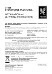
G350/7 and G350/8
GRIDDLE PLATES
INSTALLATION and
SERVICING INSTRUCTIONS
These appliances must be installed and serviced by a competent person as stipulated by the Gas
Safety (Installation & Use) Regulations.
IMPORTANT
The installer must ensure that the installation of the appliance is in conformity with these instructions and
National Regulations in force at the time of installation. Particular attention MUST be paid to -
Gas Safety ( Installation & Use ) Regulations
Health And Safety At Work etc. Act
Local and National Building Regulations
Fire Precautions Act
Detailed recommendations are contained in
Institute of Gas Engineers published
documents :
IGE/ UP/ 1, IGE/ UP/ 2
BS6173 and BS5440
These appliances have been CE-marked on the basis of compliance with the Gas Appliance Directive for the
Countries, Gas Types and Pressures as stated on the Data Plate.
WARNING - TO PREVENT SHOCKS, ALL APPLIANCES WHETHER
GAS OR ELECTRIC, MUST BE EARTHED
On completion of the installation, these instructions should be left with the Engineer-in-Charge for reference
during servicing. Further to this, The Users Instructions should be handed over to the User, having had a
demonstration of the operation and cleaning of the appliance.
IT IS MOST IMPORTANT THAT THESE INSTRUCTIONS BE CONSULTED BEFORE INSTALLING AND
COMMISSIONING THIS APPLIANCE. FAILURE TO COMPLY WITH THE SPECIFIED PROCEDURES MAY
RESULT IN DAMAGE OR THE NEED FOR A SERVICE CALL.
PREVENTATIVE MAINTENANCE CONTRACT
In order to obtain maximum performance from this unit we would recommend that a Maintenance Contract be
arranged with SERVICELINE. Visits may then be made at agreed intervals to carry out adjustments and
repairs. A quotation will be given upon request to the contact numbers below.
Falcon Foodservice Equipment
HEAD OFFICE AND WORKS
Wallace View, Hillfoots Road, Stirling. FK9 5PY. Scotland.
SERVICELINE CONTACT PHONE - 01438 363 000
FAX - 01438 369 900
T100690 Ref. 1
Warranty Policy Shortlist
Warranty does not cover :Correcting faults caused by incorrect installation of a product.
Where an engineer cannot gain access to a site or a product.
Repeat commission visits.
Replacement of any parts where damage has been caused by misuse.
Engineer waiting time will be chargeable.
Routine maintenance and cleaning.
Gas conversions i.e. Natural to Propane gas.
Descaling of water products and cleaning of water sensors where softeners/conditioners are not fitted, or are
fitted and not maintained.
Blocked drains.
Independent steam generation systems.
Gas, water and electrical supply external to unit.
Light bulbs.
Re-installing vacuum in kettle jackets.
Replacement of grill burner ceramics when damage has been clearly caused by misuse.
Where an engineer finds no fault with a product that has been reported faulty.
Re-setting or adjustment of thermostats when unit is operating to specification.
Cleaning and unblocking of fryer filter systems due to customer misuse.
Lubrication and adjustment of door catches.
Cleaning and Maintenance
Cleaning of burner jets
Poor combustion caused by lack of cleaning
Lubrication of moving parts
Lubrication of gas cocks
Cleaning/adjustment of pilots
Correction of gas pressure to appliance.
Renewing of electric cable ends.
Replacement of fuses
Corrosion caused by use of chemical cleaners.
SECTION 1 - INSTALLATION
UNLESS OTHERWISE STATED, PARTS WHICH HAVE BEEN PROTECTED BY THE MANUFACTURER
ARE NOT TO BE ADJUSTED BY THE INSTALLER
1.1 MODEL NUMBERS, NET WEIGHTS
and DIMENSIONS
MODEL
WIDTH DEPTH HEIGHT WEIGHT WEIGHT
mm
mm
mm
kg
lbs
G350/7 & 7P
350
650
385
38
85
G350/8 & 8P
700
650
385
73
162
A "P" suffix denotes propane operation.
1.2 SITING
The griddles can be installed on a table, counter top
or alternatively upon a purpose-made stand.
The unit can be positioned to within 75mm of a
combustible wall at the back and sides. There should
be a minimum vertical clearance of 900mm above top
edge of appliance flue to any overhanging
combustible surface.
Important
If unit is to be installed with other matching appliances
of the Falcon 350 series, the instructions for all units
must be consulted to determine the necessary
clearance to any combustible rear wall or overlying
surface. Some appliances require greater clearances
than others, and the largest figure quoted in the
individual Instructions will therefore determine
clearance for complete suite of adjoining appliances.
1.3 VENTILATION
Adequate ventilation, whether natural or mechanical,
must be provided to ensure sufficient fresh air for
combustion and for removal of combustion products,
which may be harmful to health. Recommendations
for ventilation for Catering Appliances are given in
BS.5440:2. Further, to ensure sufficient room ventilation, guidance on the volume of ventilation air
required for different kinds of catering equipment is
given in the table. For multiple installations the
requirements should be added. Installation should
be made in accordance with local and/ or national
regulations applying at the time, and a competent
installer must be employed.
The appliance flue discharges vertically through grille
at rear of hob. There must be no direct connection of
the flue to any mechanical extraction system or
outside air. Siting appliance under a ventilated
canopy is the ideal arrangement.
EQUIPMENT
Ventilation Rate Required
ft3/min
m3/ min
Range, Unit Type
17
600
Pastry Oven
17
600
Fryer
26
900
Grill
17
600
Steak Grill
26
900
Boiling Pan
17
600
Steamer
17
600
Sterilizing Sink
14
500
Bains Marie
11
400
8.5 - 14
300 - 500
Tea/ Coffee Machine
1.4 GAS SUPPLY
The incoming service must be of sufficient size to
supply full rate without excessive pressure drop.
A gas meter is connected to service pipe by Gas
Supplier. Any existing meter should be checked,
preferably by Gas Supplier, to ensure that the meter
is of adequate capacity to supply the unit, and other
associated equipment. This is particularly important
when a number of units are being installed.
Installation pipework should be fitted in accordance
with IGE/UP/2. The size of the pipes from the meter
to the appliance must be not less than that of the
appliance inlet connection, Rp1/2 (1/2" BSP female).
An isolating cock must be located close to the
appliance to facilitate shut-down during an
emergency or routine servicing. The cock must be
easily accessible to the user. The installation must be
tested for gas-tightness; details are given in
IGE/UP/1. The adjustable governor supplied must
be fitted to natural gas appliances.
1.5 ELECTRICAL SUPPLY
Not applicable to these appliances.
1.6 WATER SUPPLY
Not applicable to these appliances.
1.7 HEAT INPUTS (net) NATURAL and PROPANE GAS
Model
Natural Propane
G350/7 & 7P 5.2kW
4.65kW
G350/8 & 8P 2 x 5.2kW 2 x 4.65kW
1.8 INJECTOR SIZES NATURAL and PROPANE GAS
Burner
Main
Pilot
Natural
é2.1mm
SIT No. 36
Propane
Amal 180
SIT No. 19
1.9 GAS PRESSURE
NATURAL and PROPANE GAS
Pressure test point is located behind front facia panel.
Supply Pressure Burner Pressure
mbar inches w.g. mbar inches w.g.
NATURAL 20
8
16
6
PROPANE 37
14.8
37
14.8
An adjustable governor Rc1/2 (1/2" BSP) is provided
on Natural Gas models.
1.10 BURNER ADJUSTMENTS
1.10.1 Aeration Adjustment - Natural Gas
Burners are fitted with fixed injectors. Aeration
adjustment is set by manufacturer by means of a
screw in burner throat. After setting pressure, flame
cone height should be approximately 12mm.
1.10.2 Low Flame Setting
The gas control is provided with a low flame setting.
Low flame adjustment has been set and sealed by
manufacturer by means of a bypass screw in gas tap
to approximately one third full rate.
SECTION 2 - ASSEMBLY and
COMMISSIONING
2.1 ASSEMBLY
Place unit in position, and level using feet adjusters.
If unit requires to be mounted upon a stand, refer to
details supplied with stand.
Remove any packing material and ensure that
burners are correctly located over injectors.
2.2 CONNECTION TO GAS SUPPLY
The unit is furnished with a compression elbow fitting,
terminating in an R1/2 thread for connecting to mains.
The gas supply piping and connection to unit must be
installed in accordance with the regulations listed on
the cover of this manual.
On Natural Gas appliances, the adjustable governor
must be fitted in supply, being securely fixed in a
position enabling adjustment to be made during
commissioning. DO NOT fit a governor to Propane
models.
A gas isolating cock must be fitted in supply, in a
position readily accessible to operator.
2.3 CONNECTION TO AN ELECTRICITY SUPPLY
Not applicable to these appliances.
2.4 CONNECTION TO A WATER SUPPLY
Not applicable to these appliances.
2.5 PRE-COMMISSIONING CHECK
2.5.1 Setting Gas Pressure (Natural Gas Only)
Connect a suitable pressure gauge to test point
located behind facia panel. Light burners in
accordance with procedure detailed in User
Instructions and set gas pressure as specified in
Section 1.9.
2.5.2 Aeration Adjustment
Check by observing through inspection aperture and
window, that burner cone lengths are in accordance
with Section 1.10.1.
2.5.3 Low Flame Check
Check by observing through inspection aperture and
window, that flame reduces when control is turned to
low flame setting in accordance with Section 1.10.2.
Further observe that flame is stable.
2.5.4 Gas Tightness
After installation, the engineer responsible should
check gas tightness and ensure unit operates
satisfactorily before hading over to user.
2.6 INSTRUCTION TO USER
After installing and commissioning the appliance,
hand the User's Instructions to the user or purchaser
and ensure that the person(s) responsible
understands the instructions for lighting, cleaning
and correct use of the appliance. It is important to
ensure that location of gas isolating cock is made
known to user, and the procedure for its operation in
an emergency be demonstrated.
SECTION 3 - SERVICING
and CONVERSION
Important
BEFORE ATTEMPTING ANY SERVICING, TURN
OFF ISOLATING COCK AND TAKE STEPS TO
ENSURE THAT IT CANNOT BE INADVERTANTLY
TURNED ON.
AFTER ANY MAINTENANCE TASK, CHECK THE
APPLIANCE TO ENSURE THAT IT PERFORMS
CORRECTLY AND CARRY OUT ANY NECESSARY
ADJUSTMENTS AS DETAILED IN SECTION 1.
After carrying out any servicing or exchange of gas
carrying components -
ALWAYS CHECK FOR GAS TIGHTNESS!
3.1 CONVERSION PROCEDURE CHECK LIST
For conversion to NATURAL GAS, add correct
governor and set burner pressure.
For conversion to PROPANE GAS, remove governor
from gas circuit.
Other considerations:
CHANGE INJECTORS
ADJUST BYPASS SCREW TO LOW RATE
ADJUST BURNER AERATION
CHANGE DATA PLATE
On completion, re-apply any seals and locking nuts.
3.2 REMOVAL OF CONTROL PANEL
Proceed as follows:
Remove spillage tray.
Pull off gas control knob.
Undo fixings in upper flange of facia panel and allow
panel to drop down. Withdraw panel sufficiently to
enable spark igniter leads to be disconnected at rear
before removal.
Note
When re-fitting spark electrode terminal, ensure it is
turned away from manual ignition hole in bulkhead.
3.3 BURNERS
Burners should be cleaned periodically to maintain
maximum performance.
3.3.1 Main Burner
To gain access to burner, remove griddle plate.
Remove burner by lifting it slightly at rear.
Carefully move it back to clear injector. Injectors
may also be removed at this stage if required.
Refer to Section 3.4.
Clean burner with a wire brush. Ports may be cleared
with a suitable metal broach, shaking debris clear,
or if possible blowing it away with compressed air.
When replacing burner, ensure that rear locating pins
are properly located.
Check flame cone lengths in accordance with
Section 1.10.1.
Replace all parts in reverse order and check for gas
tightness.
3.3.2 Pilot Assembly
To remove, proceed as follows:
a) Remove griddle plate, burner and facia panel as
previously described.
b) Release thermocouple fixing nut and remove
thermocouple from assembly.
c) Release pilot pipe fixing nut from pilot assembly.
Take care not to lose injector removed with nut.
d) Undo fixings which secure pilot assembly and
remove with electrode and ignition lead.
Replace spark electrode if required and re-assemble
in reverse order.
3.4 INJECTORS
3.4.1 Main Injector
Lift off griddle plate and remove burner as detailed
above. Injectors may now be unscrewed.
Soak it in a suitable solvent to remove any debris and
wipe with a soft cloth. Do not use metal objects to
clear injector hole.
Check face-to-face seals are clean before re-fitting.
3.5 THERMOCOUPLE
To remove, proceed as follows:
a) Remove griddle plate, burners and control panel as
detailed in the relevant sections of this document.
b) Undo tubing nuts at both pilot end and gas control.
c) Manoeuvre thermocouple clear.
When fitting a new thermocouple, coil excess in a
similar manner to original. Take care not to bed tubing
to less than a 12mm radius.
3.6 PIEZO IGNITER/SPARK ELECTRODE
3.6.1 Piezo Igniter
To remove, proceed as follows:
a) Remove facia panel.
b) Pull off igniter lead and, from inside, remove nut
which secures igniter to facia panel.
Replace parts in reverse order and check that pilot
ignites from spark. Refer to User Instructions for
lighting procedure.
3.6.2 Spark Electrode
a) Remove griddle plate and facia panel.
b) Release thermocouple tubing nut and remove
thermocouple from pilot assembly.
c) Remove spark ignition lead from electrode by
releasing M4 securing nut.
d) Release tubing nut which secures electrode to
pilot assembly and remove electrode.
Replace parts in reverse order.
Note
When re-fitting spark electrode terminal, ensure it is
turned away from manual ignition hole in bulkhead.
3.7 GAS TAP
To gain access to gas control, remove control panel
as detailed in Section 3.2 and proceed as follows:
a) Undo nut securing burner feed pipe to control.
b) Release pilot tubing nut from control and ease pilot
tube clear of location.
c) Remove fixings which secure control to float rail.
d) Manoeuvre control to enable thermocouple
removal.
e) Withdraw control.
When replacing control, ensure sealing gasket is in a
serviceable condition and check gas tightness.
To clean and lubricate tap, proceed as follows:
f) Undo screws that fix front securing plate and at the
same time, hold plate against internal spring
pressure.
g) Carefully withdraw plate, complete with operating
spindle.
h) Withdraw exposed rod, spring, brass washer and
sealing washer. Take care not to lose any of these
small parts.
j) Withdraw plug and clean it with a soft rag.
Also clean mating hole in control body.
Sparingly re-grease plug with an approved heat
resistant grease.
Re-assemble strictly in reverse order. Take care with
central pin assembly.
i.e. Fit spring to pin first, then brass washer and finally
rubber sealing washer.
When inserting assembly into plug, ensure sealing
washer fits snugly into recess at bottom of hole in
plug.
When re-assembling operating spindle, ensure that
niting pin engages in the plug slot.
Adjusting Low Flame Setting
Low flame setting is adjustable by means of a screw
on control front. Refer to Figure 1 and Section 1.10.2.
If it is necessary to adjust flame, adopt the following
procedure:
k) Turn adjusting screw fully clockwise, then unscrew
approx.
Natural Gas - 1/2 to 3/4 turn.
Propane Gas - 1/3 to 1/2 turn.
m) Light burner and turn to low flame setting.
n) Observe that flame is stable and if required,
carefully adjust screw within the limits given for
satisfactory operation. Turning screw in an
anti-clockwise direction will increase flame and
vice-versa.
Low flame setting screw
On two burner models, both burners require
adjustment.
When replacing control, ensure sealing gasket is in a
serviceable condition and check gas tightness.
Take care not to bend thermocouple tubing to less
than 12mm radius.
3.8 GOVERNOR
This applies to Natural Gas appliances only.
The type of governor used is maintenance free.
Check that blue dust cap covering vent is fitted and in
good condition. This protects breather hole.
SECTION 4 - SPARES
When ordering spare parts, always quote appliance
type and serial number. This information will be found
on the data plate, located at unit rear.
In addition, the serial number is also printed on an
identification label on the unit front.