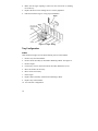
1
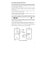
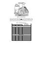
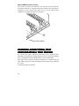
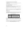
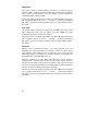
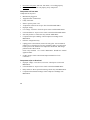
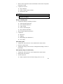
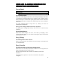
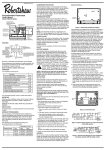
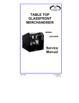
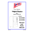
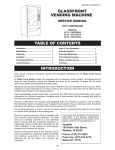
ROUND FRONT MERCHANDISER ECM Series MODELS: 3136 3137 3138 3139 Service Manual August 1998 P/N 4209706 Rev. B Table of Contents SPECIFICATIONS ............................................................1 INTRODUCTION ...............................................................2 UNPACKING.....................................................................3 INSTALLATION ................................................................4 LOADING PRODUCTS.....................................................7 CHANGING AUGER TIMING, TRAY CONFIGURATION & TRAY SPACING...........................10 CONTROLLER FUNCTIONS..........................................16 Sales Mode ..............................................................16 Service Mode ...........................................................18 REFRIGERATION FUNCTIONS & OPERATION ..........27 Refrigeration Troubleshooting ..................................27 CARE AND CLEANING SCHEDULE FOR PREVENTIVE MAINTENANCE ......................................33 PARTS ORDERING PROCEDURE ................................34 BEFORE CALLING FOR SERVICE ...............................35 SCHEMATIC ...................................................................36 Record the Model Number and Serial Number of your machine below. The Model and Serial numbers are needed for you to obtain quick service and parts information for your machine. The numbers are given on the identification plate located on the back side of the cabinet of the machine. MODEL NUMBER: ______________________________________________ SERIAL NUMBER: ______________________________________________ ii SPECIFICATIONS Physical Dimensions MODEL WIDTH DEPTH HEIGHT WEIGHT Inches cm Inches cm Inches cm Pounds kg 3139 2-Wide 21 53 36 91 72 183 520 236 3136 3-Wide 29-5/16 74 35-1/2 87 72 183 577 261 3137 4-Wide 35-3/16 89 35-1/2 87 72 183 648 295 3138 5-Wide 41 104 35-1/2 87 72 183 778 354 Electrical 115 Volt AC: 60 Hz, 7.5 Amps (± 10%) 230 Volt AC: 50 Hz, 3.75 Amps (± 10%), 862.5 Watts Transformer: 24 Volt AC Refrigeration System Type: 2-Wide 3, 4 and 5-Wide Controls: Electronic Refrigerant: R-134a Charge: 2-Wide 3, 4 and 5-Wide 1/4 HP, 2.6 amp Hermetically Sealed 1/3 HP, 3.8 amp Hermetically Sealed 5.3 Ounces 5.9 Ounces Factory Configuration 2-Wide: 14 Select - Expandable to 18 3-Wide: 24 Select - Expandable to 36 4-Wide: 36 Select - Expandable to 48 5-Wide: 40 Select - Expandable to 60 Coinage MDB version - any MDB peripheral device 1 INTRODUCTION This manual contains instructions, service and installation guidelines for the Round Front Merchandiser ECM Series product line. All Glass Front models are equipped with an electronic control system. All programming of the vend functions, pricing and features is done at the controller. Changes can be made without any additional accessories or remote parts. Selections can be priced individually from $.05 to $99.95 in five cent increments (U.S. currency). When adapted to accept international or foreign currency, the maximum vend price will be 255 times the smallest denomination of coin being accepted. Features include: • Multi Drop Bus (MDB) coin handling mechanism • Self-diagnostics and cash accountability • Multi Vend, Free Vend, Bonus Vend and Promo Vend features • Hermetically sealed refrigeration system with R-134a refrigerant • Programmable electronic control of the refrigeration unit • Motorized delivery, electronically controlled CAUTION: This vendor utilizes DC motors. Do not attempt to turn augers by hand. Motor damage could occur. • • • Audible feedback indicates when a product has been vended or when an error condition exists. No change or loss of program/memory because a power failure Cash accountability records Total Cash transactions and Total Vend cycles performed by the vendor. Information for individual selections, complete range (rows) or total machine can be compiled and used for inventory and ordering records. The vending sequence is "first-in, first-out" for each selection, eliminating the need for stock rotation to maintain fresh products in the vend area. This manual should be read thoroughly to familiarize yourself with the functions of all components, along with the features that are available. The initial set-up of a vending machine is a very important step of insuring that the equipment operates in a trouble-free manner. Following the instructions at the initial installation of the machine will avoid service problems and minimize set-up time. 2 Should you have any questions pertaining to information in the manual, replacement parts or the operation of the vendor you should contact your local distributor or: VendNet 165 North 10th Street Waukee, Iowa 50263 - USA Phone: 515-274-3641 Parts Fax: 515-987-4447 Sales Fax: 515-274-0390 E-Mail: [email protected] UNPACKING This vendor was thoroughly inspected before leaving the factory and the delivering carrier has accepted this vendor as their responsibility. Note any damage or irregularities at the time of delivery and report them to the carrier. Request a written inspection report from the claims inspector to file any claim for damage. File the claim with the carrier (not the manufacturer) within 15 days after receipt of the machine. Carefully remove the outside packing material so as not to damage the finish or exterior of the machine. Adhesive residue can be removed with denatured alcohol or common household vinegar. Inspect the machine for concealed shipping damage. Report any damage hidden by the shipping material directly to the delivering carrier on a hidden damage report. Record the model number and serial number of the vendor for your records. These numbers can be found on the Serial Plate on the rear of the cabinet and/or inside the vendor. Refer to these numbers on all correspondence and inquiries pertaining to this vendor. Remove the Knock-A-Way Support by placing a spacer under the vendor, inserting a screwdriver or prying tool into the groove and splitting it in two. Discard the washers located on each side of the wooden supports. Turn the leveling screws in as far as possible. See Figure 1. 3 A10109 Figure 1. Removing the Knock-A-Way Supports INSTALLATION Consult local, state and country codes and regulations before installation of the vendor. CAUTION: To insure reliability and maintain manufacturers equipment warranty, machine must NOT be placed in an environment where the temperature is greater than 90°°F/32°°C and the relative humidity is 65% or greater. 1. Position the vendor in its place of operation no further than six (6) feet (2 m) from the power outlet or receptacle WARNING: DO NOT USE EXTENSION CORDS. Extension cords can cause problems. 2. 3. 4. 5. 6. 4 Leave at least six (6) inches (15 cm) of space between the back of the machine and any wall or obstruction for proper air circulation. Retrieve the keys to the vendor from the coin return cup. Open outer door and remove all internal packing material. Check that the door will open fully without interference. Level the vendor, making sure all levelers are touching the floor. The vendor must be level for proper operation and acceptance of coins through the coin mechanism. Grounding (Earthing) & Electrical Before connecting the vendor, the integrity of the main electrical supply must be checked for correct polarity, presence of ground (earth) and correct voltage. These checks should be repeated at 6-month intervals with the routine safety electrical testing of the vendor itself. For proper operation of any equipment utilizing electronically controlled components, the equipment should be placed on an isolated or dedicated noise-free circuit. For 115-Volt vendors the circuit should be a minimum 15 Amp, 60 cycle, properly polarized and grounded (earthed). For 230-Volt vendors the circuit should be a minimum 7.5 Amp, 50 cycle, properly polarized and grounded (earthed). To verify that the receptacle is properly grounded (earthed) and polarized, insert one probe of a Multi-Meter (set to check AC line voltage) or a test light in the ground (earth) terminal (hole) and the other probe into the hot terminal of the outlet. If the receptacle is not properly grounded (earthed) or polarized, you should contact a licensed electrician to correctly polarize and/or ground (earth) the receptacle to ensure safe operation. A noise suppressor has been installed in this machine to compensate for any signal noise that could interfere with the normal operation of the controller. Shown in Figure 2 and Figure 3 are two properly grounded (earthed) and polarized wall outlets. Figure 2 shows two 230-Volt wall outlets. Figure 2. 230-Volt Outlets 5 A10116 Figure 3. 115-Volt Outlet Power Switches The vendor has a Power Switch operated by the outer door. The switch is located in the upper right corner of the cabinet. When the door is closed, the switch is placed ON, putting the vendor in the Sales Mode. When the door is opened, the switch is placed OFF, removing power to the machine. To operate the machine with the door open, the switch must be manually placed in the ON position: Use the plastic key furnished in the Service Package. Insert key and twist 90° to lock the switch in the ON position. See Figure 4. Figure 4. Location of Interlock Switch 6 A second power switch is located on the transformer panel along with a 3-amp breaker. With the door open and the key in the interlock switch, this switch will shut-off the light and controller and leave the evaporator fans running. See Figure 5. The 3-amp breaker is protection for the controller. Figure 5. Power Switch and 3-Amp Breaker LOADING PRODUCTS To load products, lift the tray slightly and pull forward until the tray stops. The upper-most trays tilt for easier loading. Load products from front to back, making sure all items fit freely between the augers. Do not attempt to force oversize items or packages into the spaces. Do not skip a space. Place the product on the bottom of the compartment on the product augers, with the label facing the front of the machine for easy identification by the customer. See Figure 6. When finished loading each tray, return the tray to its proper standby position. All trays must be pressed to the rear of the cabinet and properly seated in the detent position. 7 A10114 Figure 6. Loading Example The size of the item being vended must be larger than the diameter of the auger being used to vend properly. Undersize items could cause vend problems. If the product does not fit the auger properly, use a different pitched auger. See Table 1 for augers available from your distributor or service entity. Table 1. Available Augers (Coil) PRODUCT SIZE Width Thick Qty AUGER (COIL) PART NUMBERS CANDY 2-3/4 1-3/16 15 4200272-000 2-3/4 15/16 18 4200272-001 2-3/4 21/32 24 4200272-002 2-3/4 1/2 20 4200272-003 2-3/4 1-1/2 12 4200272-004 2-3/4 2-1/32 9 4200272-005 2-3/4 3-3/32 6 4200272-006 SNACK (CRISPS) 8 5-1/2 1-13/16 10 4200272-007 5-1/2 1-1/2 12 4200272-008 5-1/2 1-3/16 15 4200272-009 5-1/2 2-11/16 7 4200272-010 5-1/2 2-5/8 8 4200272-011 Scroll Locks (3 & 4-wide trays only) Rubber scroll locks are included in the service packet and are used to lock the price scrolls in place so they will not move due to tray vibrations etc. Set the price to where needed and insert the scroll lock into the small hole beside the scroll port. See Figure 7. Figure 7. Scroll Locks Product Ejectors Product ejectors can be added to the end of the augers to assist the product out of the tray area (see figure 8). They can also be moved on the auger to adjust timing. Order P/N 4025748. Figure 8. Product Ejectors 9 PRICE LABELS (5-wide tray only) The 5-wide tray utilizes price labels for each selection. The tray label has selections A1 thru A0 etc. showing on the front rail. When a snack selection is configured in a tray, slide the price label over to cover the selection label (usually an even numbered selection). See Figure 9. Figure 9. Price Labels CHANGING AUGER TIMING, TRAY CONFIGURATION & TRAY SPACING By re-timing the augers, difficult-to-vend items can be dispensed more dependably. By altering tray spacing, larger items can be vended. By changing the tray configuration, different product mixes can be accommodated. Each auger can be rotated in 20-degree increments for a different drop-off point. Most items can be vended successfully when the auger end is positioned at 6 o'clock. To change the auger end position: 10 Retiming 2-Wide 1. Remove the tray from the vendor. 2. Remove the two screws from the top of the motor assembly. See Figure 10. 3. Lift up slightly on the motor assembly. 4. Pull the auger away from the motor until the auger hub separates from the motor shaft. 5. Rotate the auger to the desired position and reinsert the hub into the motor. 6. Slide the motor assembly down, locating the tabs in the slots in the bottom of the tray. Be sure the rib in the tray is locked to the tabs of the auger coupling. 7. Reinsert the two screws into the top of the motor assembly. See Figure 10. 8. Replace the tray in the vendor. Figure 10. 2-WideTray, Motor Mount Assembly Retiming, 3, 4 & 5-Wide 1. Remove the motor cover. 2. Raise the motor slightly and pull forward on the auger until it separates from the motor. See Figure 11. 3. Rotate the auger to the desired position and re-insert the auger coupling into the motor. 11 4. Make sure the auger coupling is seated over the vertical rail or retaining rib on the tray. 5. Replace the motor cover making sure it is securely tightened. 6. Pull forward on the auger to verify proper installation. A10112 Figure 11. Auger Timing Tray Configuration 2-Wide Order the desired augers. See the Parts Ordering section of this manual. 1. Remove tray from the machine. 2. Remove motor assembly as described in Retiming 2-Wide. See Figure 10. 3. Remove augers. 4. If necessary, remove motors from motor assembly. Retain the screws. 5. Move the dividers as necessary. 6. Move motors if necessary. 7. Insert augers. 8. Replace motor assembly as described in Retiming 2-Wide. 9. Replace tray in the machine. 10. Test vend new configuration. 12 3, 4 & 5 Wide Candy to Snack 1. Order the conversion kit from your local distributor or service entity. 2. Unplug and remove the tray assembly from the vendor. Place the tray harness in the tray before removal. 3. Remove the motor cover and retain any hardware. 4. Remove existing tray divider and store for possible future use. 5. Remove existing auger assemblies and store for possible future use. 6. Remove the existing "even" numbered motor. This motor will not be needed. 7. Dress terminals removed from the motor around the tray harness and tape in place. 8. Move the "odd" numbered motor to the center slot of the compartment. 9. Install the auger retainer furnished as part of the conversion kit. 10. Install auger assembly furnished as part of the conversion kit, making sure the motor coupling properly engages the motor and is securely snapped over the vertical rail or retaining rib on the tray. 11. Re-assemble the motor cover removed in step 3. 12. Replace the tray assembly into the vendor making sure that the tray is properly located and latched and connect the tray harness 13. Set the selection to the desired vend price and adjust the price scroll (3 & 4 wide) or price label (5-Wide) to agree. 14. Test vend the converted selections for proper operation and price settings. NOTE: In large item selections, the selection numbers will be the "odd" numbers. For example, selections C3 and C4 are converted to a single selection, C3. Snack to Candy 1. Order the conversion kit from your local distributor or service entity. 2. Unplug and remove the tray assembly from the vendor. Place the tray harness in the tray before removal. 3. Remove the motor cover and retain any hardware. 13 4. Remove the existing auger assembly and store for possible future use. 5. Remove the auger retainer and store for possible future use. 6. Move motor from the center slot to the left slot in the compartment. 7. Add the new motor furnished as part of the conversion kit in the right hand slot of the compartment. 8. Properly wire the motor and switch. (Refer to the Schematic section for wire colors and locations). 9. Add the divider furnished as part of the conversion kit. 10. Install new auger assemblies furnished as part of the conversion kit, making sure the motor couplings properly engage with the motor and are securely snapped over the vertical rail or retaining rib on the tray. 11. Re-assemble the motor cover removed in step 2. 12. Replace the tray assembly into the vendor making sure that the tray is properly located and latched and connect the tray harness. 13. Set the selections to the desired vend price and adjust the price scrolls (3 & 4 wide) or price label (5-Wide) to agree. 14. Test vend the converted selections for proper operation and price settings. Tray Spacing The trays can be raised or lowered in one-inch (2.5 cm) increments to provide additional headroom for vending taller items. NOTE When increasing the headroom between two trays, a corresponding decrease in headroom of an adjoining tray will result. 1. To change the vertical tray spacing, follow these steps: 2. Pull out the tray to be adjusted until it stops. 3. Disengage the tray harness from its snap-open harness clamp on the righthand wall. 4. Disconnect the tray plug from its receptacle on the right side wall. 5. Lift up on the front of the tray and pull slightly forward (approximately 1/2 inch/1.25 cm) to clear the tray stop. 6. Pull tray out until it tilts down. Lift the rear of the tray and remove it from the vendor. 14 7. Disengage both left and right tray rails from their slots on the side walls: 2-Wide: - pull inward on the bottom of each rail and pull its flanges out of the slots in the front and rear. 3, 4 & 5-Wide: Pull inward on the bottom of each rail and pull its flange out of the slot. Pull each rail forward to disengage its rear tab from the hole in the rear wall. See Figure 12. 8. Relocate both left and right rails by reversing step 7. NOTE Rails must be level front to back and right to left. A10111 Figure 12. Removing a Tray Rail 9. Replace the tray by placing its rear rollers on the left and right rails and lifting up slightly on the front of the tray as you push it back until the tray latches in its detent position. 10. Plug the tray harness into its receptacle on the right side wall. 11. Re-engage the tray harness into its harness clamp and snap the clamp closed. 12. Test vend the tray in its new position to assure that the tray plug is properly seated. 15 CONTROLLER FUNCTIONS There are two modes of operation. Sales Mode: The vendor accepts deposits, pays out change, and dispenses product to the customer. The digital display and the LEDs are used to communicate with the operator and the customer. Service Mode: Used by the operator to program and service the machine. The digital display is used to communicate with the operator. Sales Mode .00 displays. The decimal point position is determined by the coin mechanism attached. When no credit has been established and a selection is made, the price for that selection displays for approximately three seconds. When credit is deposited the amount displays. Four digits are available. The credit value displays until a vend occurs, a coin return command occurs or approximately 4 minutes has elapsed at which time the credit is forfeited. Vend Cycle After a selection is made, the controller will determine if sufficient credit is available and the status of the selection. If the accumulated credit is greater than or equal to the price of the selection a vend attempt will be shown on the display. If credit is less than the selection price, the price will be flashed for 3 seconds or until a new selection key is pressed. After a successful vend, the amount of change to be returned will be displayed until all coinage is paid back. If the motor is flagged as bad, the MAKE ALTERNATE SELECTION LED flashes for 3 seconds or until a new selection is entered. If a selection is made and a vend cannot take place, (assuming that sufficient credit and change are available) the MAKE ALTERNATE SELECTION LED flashes. LEDs If the payout tubes in the coin mechanism are below the low-level sensors, the USE CORRECT CHANGE LED will light continuously unless the No Cheat Mode is enabled. See No Cheat Mode in this Options section. If no motors have been assigned or if the motor has been recorded as faulty, the MAKE ALTERNATE SELECTION LED flashes for 3-seconds or until a new selection is made. 16 Jammed Motor Condition The controller will not run motors that have been flagged as “jammed” or that have not been assigned. A motor jam is detected when power is applied to a motor and the motor fails to return to the home position within about nine (9) seconds. Motors flagged as jammed can be reset by running the motor count while in the Service Mode. Follow the instructions outlined in the Motor Count section of this manual. The flagged motor can also be reset by running a test vend of that particular selection. See the Test Vend Selections section of this manual. NOTE When vendor is attached to a Canned Drink Satellite, and a column empties. The Vendor must be placed in Service Mode to reset. Vend and Cash Counters Following a successful vend, the vend counter will be incremented by one (1) and the cash counter will be incremented by the price of the selection vended. The counter rollovers occur at 99,999,999 and $999,999.95 respectively. NOTE Test vends are not included in the counter totals. Resettable Vend and Cash Counters The resettable counters track Total Vends dispensed and Total Cash collected since last reset. The vend count and cash totals will be available by individual selections, range (rows) and entire machine. Following a successful vend, the resettable vend counter will be incremented by one (1) and the resettable cash counter will be incremented by the price of the selection vended. The counter rollovers occur at 99,999,999 and $999,999.95 respectively. NOTE Test vends are not included in the counter totals. 17 Service Mode Entering the Service Mode To change any settings or programs in the vendor, the controller must be placed in the Service Mode. To enter the Service Mode push the service mode button once. See Figure 13. Exiting the Service Mode To exit the Service Mode, push the Service Mode Button. The controller will automatically exit the Service Mode if no key is pressed for approximately twenty five (25) seconds. Figure 13. Service Mode Button Location Service Modes Push the Service Mode Button once to enter the base menu of the Service Mode. Cnt displays, to access the other modes (See Table 3) press [ K ] to scroll up or [ L ] to scroll down the menu. Table 3. Service Modes (first level) 18 MODE FUNCTION Cnt Motor Count Coin Coin Dispensing ACCt Accounting Menu PrC Price Setting tESt Motor Test Menu oPt Options Menu tEP Temperature Settings MOTOR COUNT The total number of functional motors will be displayed when Cnt is displayed and any key (except [ K ] or [ L ]) is pressed. Any new motors located during the motor count will be added to the current configuration. The controller will test each motor in the configuration. To access the other service modes, press [ K ] to scroll up or [ L ] to scroll down. COIN DISPENSING With Coin showing in the display coins can be dispensed from the coin mechanism inventory tubes. See Table 4. Table 4. Coin Dispensing PRESS KEY TO DISPENSE [ A ] lowest value coin [ B ] next lowest value coin [ C ] next greatest value coin [ D ] greatest value coin (if four coin tubes) Coins can also be dispensed from the coin mechanism with optional payout buttons located on the face of the coin mechanism. To access the other service modes, press [ K ] to scroll up or [ L ] to scroll down. ACCOUNTING MENU With ACCt showing in the display, press any key (except [ K ] or [ L ]) to enter into the accounting menu. See Table 5. Once you’re in the accounting menu press [ K ] to scroll up or [ L ] to scroll down the accounting functions. Table 5. Accounting Modes DISPLAY FUNCTION SALE Total Sales (Vend Count) CASH Cash Count rSLE Resettable Total Sales (Vend Count) rCSH Resettable Cash Count CLr Clear Resettable Values oUt Exit Accounting Menu 19 Total Sales (Vend Count) When SALE shows in the display, enter one of the following: • Single selection ([ A ] [ 1 ] for example). • Entire range (row), press the alpha key of that range (row) two times ([ B ] [ B ] for example). • Entire Machine, enter [ A ] [ G ]. The values of the vend and cash counters will be displayed as eight digit numbers, with the first four digits of each counter displayed first for a period of 2 seconds and then the last four digits displaying for 2 seconds. The controller will then wait for another selection. See example. EXAMPLE Choose selection to display 0000 displays for 2 seconds 0 8735 displays for 2 seconds 8,735 Indicates total vend count of 8,735 Cash Count When CASH shows in the display, enter one of the following: • Single selection ([ A ] [ 1 ] for example). • Entire range (row), press the alpha key of that range (row) two times ([ B ] [ B ] for example). • Entire Machine, enter [ A ] [ G ]. The values of the vend and cash counters will be displayed as eight digit numbers, with the first four digits of each counter displayed first for a period of 2 seconds and then the last four digits displaying for 2 seconds. The controller will then wait for another selection. See example. EXAMPLE Choose selection to display 0093 displays for 2 seconds 9,300.00 65.20 displays for 2 seconds $65.20 Indicates total cash sales of 9,365.20 20 Resettable Total Sales (Vend Count) When rSLE shows in the display, enter one of the following: • Single selection ([ A ] [ 1 ] for example). • Entire range (row), press the alpha key of that range (row) two times ([ B ] [ B ] for example). • Entire Machine, enter [ A ] [ G ]. The values of the vend and cash counters will be displayed as eight digit numbers, with the first four digits of each counter displayed first for a period of 2 seconds and then the last four digits displaying for 2 seconds. The controller will then wait for another selection. See example. EXAMPLE Choose selection to display 0000 displays for 2 seconds 0 0217 displays for 2 seconds 217 Indicates total vent count of 217 Resettable Cash Count When rCSH shows in the display, enter one of the following: • Single selection ([ A ] [ 1 ] for example). • Entire range (row), press the alpha key of that range (row) two times ([ B ] [ B ] for example). • Entire Machine, enter [ A ] [ G ]. The values of the vend and cash counters will be displayed as eight digit numbers, with the first four digits of each counter displayed first for a period of 2 seconds and then the last four digits displaying for 2 seconds. The controller will then wait for another selection. See example. EXAMPLE Choose selection to display 0001 displays for 2 seconds 100.00 62.50 displays for 2 seconds 62.50 Indicates total cash sales of 162.50 21 Clear Resettable Values (from Accounting Menu) When CLr shows in the display, press any key (except [ K ] or [ L ]) to clear all resettable values. Use the [ K ] or [ L ] keys to loop back through the menu. EXIT ACCOUNTING MENU When oUt shows in the display, the operator has the option to exit the accounting function menu by pressing any key (except [ K ] or [ L ]) or looping back through the accounting function menu. Use the [ K ] or [ L ] keys to loop back through the accounting function menu. Pressing any key (except [ K ] or [ L ]) will exit the Accounting Menu and place the controller back into the base menu with ACCt showing in the display. PRICE SETTING With PrC showing in the display, enter the desired selection. The current price will be displayed. Press [ K ] to scroll the price up or [ L ] to scroll the price down, then press one of the following to save the price. See Table 6. Table 5. Setting Prices PRESS KEY FUNCTION [ G ] Saves Displayed Price for Current Selection [ H ] Saves Displayed Price for Entire Row (To Which the Selection Belongs) [ J ] Saves Displayed Price for Entire Machine Once the price has been saved the display will show PrC again and wait for another selection. To access the other Service Modes, press [ K ] to scroll up or [ L ] to scroll down. To exit the Service Mode press the Service Mode Button. Vend prices can be verified in the Sales Mode. With no credit established, enter a selection to display the corresponding price. If the selection has no motors assigned, the MAKE ALTERNATE SELECTION LED will light. 22 MOTOR TEST VEND MENU With tESt showing in the display, press any key (except [ K ] or [ L ]) to enter into the test menu. Press [ K ] to scroll up the test functions or [ L ] to scroll down the test functions. See Table 6. Table 6. Motor Test Vend Functions DISPLAY SHOWS FUNCTION SLCt To Test a Particular Selection (Example:A1) ro To Test a Particular Row (Example: B) ALL To Test All Configured Motors press the [ J ] key oUt Exit the Motor Test Vend Function Menu press the [ J ] key If during a test vend a selection motor fails, the display will flash FAil for Two (2) seconds, then continue on with the test sequence as defined. To halt the test ALL - press and hold any key except J. OPTIONS MENU With oPt showing in the display, press any key (except [ K ] or [ L ]) to enter into the options menu. Press [ K ] to scroll up the options functions or [ L ] to scroll down the options functions, then press the [ E ] key to toggle the function on or off. (y = enabled, n = disabled). Pressing the [ K ] or [ L ] saves the setting and jumps to the next option within the menu. See Table 7. Table 7. Options Functions Menu DISPLAY SHOWS1 OPTIONS UL X Multi-Vend FE X Free Vend CH X No Cheat Pr X Promo Vend bn X Bonus Vend oUt Out (exits options menu) 1. X is the current status of the option (y = enabled, n = disabled) 23 Multi-Vend This feature, when on, enables multiple purchases to be made as long as adequate credit is available. Instead of immediately returning the over-deposit after a vend, the credit displays. To receive change on an over-deposit the Coin Return button must be pushed. When in the Multi-Vend Option, the display will show UL X. Press the [ E ] key to toggle the function on or off. (y = enabled, n = disabled). Pressing the [ K ] or [ L ] saves the setting and jumps to the next option within the menu. See Table 7. Free Vend This feature, when on, allows the customer to vend All items with no credit input. During the vend cycle, the display will show FrEE. Any credit accumulated prior to the vend will be returned. When in the Free Vend Option, the display will show FE X. Press the [ E ] key to toggle the function on or off. (y = enabled, n = disabled). Pressing the [ K ] or [ L ] saves the setting and jumps to the next option within the menu. See Table 7. No Cheat When a vend is attempted and there is not enough change in the coin mechanism to return exact change, the controller is said to be in exact change status. Whenever this condition occurs, a customer is at risk of not receiving exact change after a vend is made. To signal the customer of a potential loss, the USE EXACT CHANGE LED will be on. When the controller is in exact change status and the No Cheat Option is enabled, and if a customer selects an item for which exact change can not be returned, the controller will return the accumulated credit and the selection will not be vended. The USE EXACT CHANGE LED will flash to signal the customer to use exact change for the desired selection. When in the No Cheat Option, the display will show CH X. Press the [ E ] key to toggle the function on or off. (y = enabled, n = disabled). Pressing the [ K ] or [ L ] saves the setting and jumps to the next option within the menu. See Table 7. 24 Promo Vend This feature allows the customer to receive a free product if the selection corresponds to the row set for the Promo Vend and from column 1 of that row. Only one row can be set for Promo Vend at a time. The free product can only come from column 3 (A3, B3 etc.) of the same row. When in the Promo Vend Option, the display will show Pr X. Press the [ E ] key to toggle the function on or off. (y = enabled, n = disabled). After setting to y for yes (enabled), press the [ J ] key to save the status. The display will then show ro X, enter the row by pressing the [ A ] to [ E ] keys. Press the [ J ] key to save the row and take the controller back to the Promo Vend Option of the options menu. Bonus Vend This feature, when on, allows the customer to receive a free product if the selection corresponds to the Bonus Vend address. During the vend the display will show FrEE and any credit will be returned to the customer. When in the Bonus Vend Option, the display will show bn X. Press the [ E ] key to toggle the function on or off. (y = enabled, n = disabled). If the option is enabled (y), press the [ J ] key to save the setting. The display will then show b n. To set the number of vends that are required to take place before a Bonus Vend is dispensed, enter a number using the keypad (the maximum number that can be entered is 255). Press the [ J ] key to save the setting. Out (exits option menu) The display will show oUt. To exit the options menu and place the controller back into the base menu of the Service Mode. Pressing any key other than the [ K ] or [ L ] will take the controller out of the options menu and place it back in the base menu. Pressing the Service Mode Button at any time will place the controller back into the Sales Mode of Operation. 25 TEMPERATURE SETTINGS This mode is used to set the operating parameters within the refrigeration system. Table 8. Controller Default Settings SETTING DEFAULT RANGE - MIN/MAX Compressor Cut-In 69ºF (21ºC) 32ºF - 80ºF (0ºC – 26.7ºC) Compressor Cut-Out 55ºF (13ºC) 32ºF - 80ºF (0ºC – 26.7ºC) Defrost Time 10 Minutes (non-adjustable) When tEP displays, Press any key other than the [ K ] or [ L ] keys, either C (Celsius) (default) or F (Fahrenheit) displays. Press any key other than the [ J ] key to toggle the setting until the desired value (Celsius or Fahrenheit) shows. Press the [ J ] key to save the setting. C XX will then display, where C stands for cut-in temperature and XX is the current compressor cut-in temperature setting. Press either the [ K ] key (increase) or the [ L ] key (decrease) to change the temperature setting. Press the [ J ] key to save the setting. NOTE The cut-in temperature is automatically programmed to be at least 14ºF/8ºC above the cut-out setting. o XX will then display, where o stands for cut-out temperature and XX is the current compressor cut-out temperature setting. Press either the [ K ] key (increase) or the [ L ] key (decrease) to change the temperature setting. Press the [ J ] key to save the setting. Temperature display d X will then display, where if X is 1, the current temperature will be displayed in the Sales Mode once every minute. If the status of X is 0 (zero) no temperature will be displayed. Press any key other than the [ J ] key to toggle the setting, press the [ J ] key to save the setting and exit back to the options mode. 26 REFRIGERATION FUNCTIONS & OPERATION Refrigeration Control NOTE To prevent damage to the refrigeration unit when it is turned off or the power interrupted, the refrigeration unit will not restart for at least three minutes regardless of the temperature. When the temperature is above the cut-in temperature programmed, the unit is turned on. When the refrigeration unit reaches the cut-out temperature it is turned off. If the refrigeration unit runs for more than two hours without reaching the cutout temperature, the unit is turned off for the programmed ten (10) minute defrost time. It will then be turned on again automatically. Refrigeration Troubleshooting If the refrigeration unit is turned off or the power is interrupted, the refrigeration unit will not start for at least three minutes regardless of the temperature. This is done to prevent damage to the refrigeration unit. CAUTION: Breaking the refrigerant joints or seals on the system voids the unit warranty. Failure to keep the condenser coil clean and free of dirt and dust and other similar debris voids the unit warranty. Know and understand how the unit operates. Units may vary, but the operation is basically the same. Never guess at the problem; find the symptom before attempting any repair. NOTE Most refrigeration problems are electrical. The sealed hermetic system should not be worked on outside the Factory Service Center. The three things that can go wrong with a sealed system and should be repaired only at the Factory Service Center are • Low Charge - usually caused by leaks; look for oil around seals and welds. Unit will not cool properly. The capillary tube is frosted before it enters the evaporator inlet tube. 27 • Restriction in Systems (unit frost, then melts) - not cooling properly. • Bad valves - unit does not cool properly; noisy compressor. Compressor will not start Compressor has no power • Machine not plugged in. • Tripped breaker or blown fuse. • Faulty wall outlet. • Short or open in power cord. • Temperature sensor circuit is open. Check with the Multi-Meter. • Improper wiring. • Low voltage: 5% below. Check the power source with the Multi-Meter. • Overload defective: Trips too fast. Check overload with the Multi-Meter. • Start relay defective: Check start relay with the Multi-Meter. • Compressor has open windings. Check compressor windings with a Multi-Meter. • Defective refrigeration relay. • Unplug power to the machine; remove the relay plate. Use an insulated jumper wire to short the wires on relay terminals 2 and 4 or 6 and 8; then restore power to the machine. The compressor should start, indicating a problem in the control circuit. Check relay terminals 1 to 0 with a Multi-Meter. Should have 24VDC applied to them. • No DC voltage: Check control board output terminal for a loose connection. Compressor trips on Overload • Improper voltage: 5-10% above, 5% below. Check power source with Multi-Meter. • Overload defective: Trips too fast. Check overload with Multi-Meter. • Relay defective: Won’t open after starting. Check relay with Multi-Meter. • Compressor has shorted windings: Check compressor windings with Multi-Meter. 28 • Short in other component: Isolate and eliminate each electrical component until short is found. • Compressor is too hot. ♦ Dirty condenser. ♦ Faulty condenser motor or blade. ♦ Restricted air flow. CAUTION: Condenser must be kept clean of dirt and debris to allow for proper air circulation. Noisy or vibrating unit • Components rubbing or touching each other. ♦ Check fan blades and motor. ♦ Loose shrouds and harness. ♦ Copper tubing. ♦ Loose or unsecured parts. ♦ Dirty condenser fan blades. • Worn or aged compressor grommets. • Compressor ♦ Bad valves ♦ Slugging ♦ Bad windings (See Schematic 1.) ♦ Low voltage Unit short cycles • Temperature sensor defective or not mounted in the return air duct. • Defective control board. • Temperature setting set too warm. See “Refrigeration Settings” section of this manual. Unit operates long or continuously • Temperature sensor defective or not mounted in the return air duct. • Refrigeration relay shorted. • Air flow restricted ♦ Faulty evaporator motor or blades causing coils to ice over. 29 ♦ Loose connections on evaporator motor. (One motor not running.) ♦ Air flow blocked by product in front of evaporator or air duct openings. ♦ Exhaust area blocked (machine too close to wall). • Gasket leak around door. • Excessive load: After loading, unit runs longer to pull out excessive heat from product. • Shortage of refrigerant or restriction. • Bad controller. • Ambient air temperature and relative humidity exceed manufacturers operational standards. Refrigerated space too cold • Temperature sensor defective. Check with Multi-Meter. • Refrigeration control setting too cold. See “Refrigeration Settings” section of this manual. • Refrigeration relay bad. Check with Multi-Meter. • Faulty control board. Refrigerated space too warm • Temperature sensor defective. Check with Multi-Meter. • Refrigeration control setting too warm. See “Refrigeration Settings” section of this manual. • Refrigeration relay bad • Faulty control board • Restricted evaporator space 30 ♦ Evaporator motor or blades faulty, causing the coils to ice over the evaporator ♦ Condenser air flow restricted ♦ Plugged or dirty condenser ♦ Condenser motor or blades bad ♦ Blade stuck ♦ Condensing space restricted ♦ Unit placed too close to a wall. • Compressor - bad valves ♦ Capillary tube will start frosting 8 to 10 inches (20-25 cm) past evaporator connection tube. ♦ Check for oil around brazed connections. Troubleshooting circuits with Multi-Meter • To check the power source, use the voltage section of the Multi-Meter. Should measure within 5-10% above, 5% below. • Check overload. CAUTION Power must be off and fan circuit open. Using the resistance section of the Multi-Meter, check terminals 1 and 3 for continuity. If no continuity is measured (infinity), overload may be tripped. Wait 10 minutes and try again. If still no continuity, overload is defective. • Check relay (See Figure 14.) Unscrew lead terminals and remove relay from compressor. (NOTE: keep relay upright) Check terminals 1 and S, or L and S with the Multi-Meter. Replace relay if continuity exists. • Check Temperature sensor with the Multi-Meter. • Check compressor windings as shown in Figure 14. Check winding resistance with the Multi-Meter. If readings are not within 2 Ohms, the compressor is faulty. Use RXI scale. WARNING: Wiring diagrams must be followed as shown. Any miswiring can cause serious electrical hazard and potential damage or rupture component electrical parts. Table 11. Winding Resistance APPROX. RESISTANCE ACROSS TERMINALS COMMON to START: 12 Ohms COMMON to RUN: 2 Ohms RUN to START: 14 Ohms COMMON to SHELL: No Continuity 31 A10115 Figure 14. Compressor Schematic 32 CARE AND CLEANING SCHEDULE FOR PREVENTIVE MAINTENANCE Once a Month CAUTION: Always disconnect power source BEFORE cleaning or servicing. Clean Cabinet Interior: Wash with a mild detergent and water, rinse and dry thoroughly. Odors may be eliminated by including baking soda or ammonia in the cleaning solution. Plastic parts may be cleaned with a quality plastic cleaner. Remove and clean Condensate Drain Hose to eliminate any deposits that may restrict condensate water flow. The vend mechanisms must be kept clean. Any build-up can cause the mechanisms to malfunction. Do not get the cleaning solution on electrical components. To insure proper vending keep delivery slide area free of dirt and sticky substances. Clean Cabinet Exterior: Wash with a mild detergent and water, rinse and dry thoroughly. Clean occasionally with a quality car wax. Plastic exterior parts may be cleaned with a quality plastic cleaner. Every 60-days Clean Refrigeration Intake Screen: Remove screen and clean dust and debris from screen using a soft bristle brush or a vacuum cleaner. Every 6-months Clean the condenser coil and rear exhaust screen: Remove the Cover Assembly and clean the condenser coil of refrigeration unit using a soft bristle brush or vacuum cleaner. Pull the refrigeration unit and clean the rear exhaust screen of dirt and debris. Do not block the evaporator or any area of the airflow with product or supplies. 33 PARTS ORDERING PROCEDURE When ordering parts, include the following: 1. 2. 3. 4. 5. 6. 7. 8. 9. Shipping address. Address where the invoice should be sent. The number of parts required. The model number and serial number of the machines. Any special shipping instructions. Carrier desired: air or air special, truck, parcel post, or rail. Signature and date. If a purchase order number is used, be sure that it is legible and visible. Correct part number and description from the pertinent part and/or parts manual. NOTE When “Right” and “Left” are used with a part name, it is taken to mean that the person is facing the machine with the door closed. 10. Mail your order to VendNet 165 North 10th Street Waukee, Iowa 50263 - USA Phone: 515-274-3641 Parts Fax: 515-987-4447 Sales Fax: 515-274-0390 E-Mail: [email protected] All orders are carefully packed and inspected prior to shipment. Damage incurred during shipment should be reported at once and a claim filed with the terminating carrier. If you do not have the right parts manual, contact the above address. VendNet will provide a copy for you, if available. Do not wait to order until you receive the parts manual; instead use the most accurate description you can. Include the model number and serial number of the machine, the name of the assembly in which the part is used, and if practical, a sample part. Furnish any information to enable our Parts Department to pinpoint the exact part needed. 34 BEFORE CALLING FOR SERVICE Please check the following • Does your machine have at least 6-inches of clear air space behind it? • If the power is turned on at the fuse box, is the machine the only thing that doesn’t work? • Is the machine plugged directly into the outlet? WARNING: Extension cords can cause problems. DO NOT USE EXTENSION CORDS. • Is the evaporator coil free of dust and dirt? • Is the condenser coil free of dust and dirt? • Is the compressor free of dust? (A blanket of dust can prevent the compressor from cooling in between workouts). • Is the circuit breaker at the fuse box reset? • Are evaporator fans running? To check if fans are running take a small piece of paper in front of the evaporator coil and see if the evaporator fans will blow the paper away. • Is the condenser fan running? Fold a sheet of 8 1/2” x 11” paper in half. Place the paper in front of the condenser coils and see if it draws the paper to it. • Is the shelf in front of the evaporator coil clear? (No tools, product, or other air-restricting items). • Is the cold control set as specified? NOTE Setting the temperature colder accelerate cooling of product. does not 35 SCHEMATIC 36 37