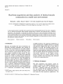
1
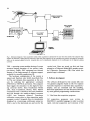
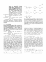
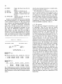
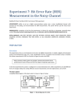
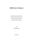
Computer Methods and Programs in Biomedicine 22 (1986) 259-265
Elsevier
259
CPB 00775
Real-time acquisition and data analysis of skeletal muscle
contraction in a multi-user environment
R i c h a r d L. Lieber, D e a n E. Smith *, R. Clark Campbell and A l a n R. H a r g e n s
Division of Orthopaedics and Rehabilitation, Department of Surgery ( V-151), Veterans Administration Medical Center,
and University of California, 3350 La Jolla Village Drive, San Diego, CA 92161, U.S.A.
A data acquisition system is described which acquires data from contracting skeletal muscle. The system is designed to
run in a multi-user environment while acquiring contractile data in real-time. Time dedicated solely to laboratory
experiments is thus eliminated. A menu-driver is included to allow users to enter experimental c o m m a n d s with or
without c o m m a n d arguments. Error monitoring functions prevent operator errors from causing data loss. Data storage
in both ASCII and binary formats maximizes file flexibility, readability and accessibility. Finally, an on-line tutorial and
help facility is provided for user training. The system developed is applicable to any experimental environment involving
data acquisition, storage and analysis.
Data acquisition
Muscle contraction
Time-sharing
I. Introduction
Recently, the number and type of laboratory applications involving computers have greatly increased. This trend reflects the increased availability of low-cost mini- and microcomputer hardware
and an explosion in the amount and type of software support available for these systems. We have
developed a number of real-time data acquisition
systems for studies of skeletal muscle contraction
which rely on state-of-the-art hardware implementations [5-7,9,10]. However, many biological applications require the use of ordinary hardware in
an environment maximizing data acquisition efficiency and enabling the inexperienced computer
user to perform sophisticated biological experiments. This report presents a system designed to
acquire contractile data from active skeletal muscle
in a multi-user environment using commonly
* Present Address: Papyrus Systems, 626 Cordova Place, Davis,
CA 95616, U.S.A.
On-line analysis
available hardware. The approach implements as
much commercially available software as possible
and generates original code only for that which is
specific to our task. The resulting program is applicable to virtually any data acquisition environment involving transducer calibration, disk storage
and file analysis. Because the program executes all
time-critical operations at the highest priority,
several users may use system resources as they
become available, thus decreasing time dedicated
to laboratory experimentation.
2. Hardware development
The data acquisition and analysis system developed is based on the Digital Equipment Corporation (DEC) LSI-11/23 + [3] running under
the TSX + operating system [12]. The LSI-11 Qbus was selected for this application due to its
powerful input/output bus architecture which is
well suited for data acquisition applications. The
0169-2607/86/$03.50 © 1986 Elsevier Science Publishers B.V. (Biomedical Division)
260
ANALOG-TO-DIGITAL
CONVERTER
I
\
LSI -11/23 +
COMPUTER
1
OSCILLOSCOPE
DISPLAY
[
~.1
F - ' - ' ~ I I', . . . . . . . . . . . I/
"
,LL.dl
l/
STIMULATOR
I
DIGITAL-TOANALOG
CONVERTER
,..."
/
//
v
CONSOLE
TERMINAL
Fig. 1. Schematicdiagram of data acquisition system. Data acquisition is initiated by the user from the console. The computer then
triggers the stimulator, causing muscle contraction. Real-time data acquisition at the transducer then permits recording of contractile
force via the analog-to-digitalconverter. Acquired data can be immediately displayed on the oscilloscope via the digital-to-analog
converter.
TSX + operating system enables sharing of system
resources during execution of low priority tasks
(see below). Finally, DEC equipment was selected
because of the large amount of software support
available for scientific applications [2].
The hardware configuration of the system is
typical and therefore only briefly described (Fig.
1). The user initiates data acquisition at the console by selecting the appropriate c o m m a n d
( T W I T C H or TETNUS, see below). The computer
then triggers the stimulator via the digital-to-analog converter (DAC; Data Translations Model
2781, Data Translations, Boston, MA). Muscle
contraction force is sensed by the force transducer
and fed through the analog-to-digital converter
( A D C ) into c o m p u t e r memory. Transducer
calibration occurs prior to data acquisition under
computer control. Acquired data are immediately
displayed on a nonstorage oscilloscope using two
DACs; one for the horizontal axis and one for the
vertical axis. Data are stored on disk and later
plotted on a Tektronix Model 4051 graphics terminal (Tektronix, Beaverton, OR) from which the
printed copy is obtained.
3. Software development
The software developed for the system falls into
two general categories based on the two separate
functions required: (1) real-time data acquisition/
display, and (2) command and file handling.
Real-time applications are first discussed, followed
by more general programming considerations.
3.1. Real-time data acquisition programs
All acquisition p r o g r a m s were written in
MACRO-11 assembly language in order to permit
rapid, real-time acquisition and execution of the
261
TSX + assembly language instructions which are
specific to real-time programs. In the multi-user
environment, real-time data acquisition requires
certain special programming considerations. For
example, under the TSX + operating system the
'job' (in this case, data acquisition) must be locked
in memory to prevent it from being removed from
memory and temporarily placed on disk by the
operating system scheduler. These 'disk swaps'
delay acquisition by an unknown amount. Additionally, acquisition must be executed at the
highest priority to prevent the system from leaving
the job once initiated. Finally, because the highest
priority tasks are interrupt service routines, the
entire data acquisition routine is entered via an
interrupt generated by the system real-time clock
(Data Translations Model 2580). Thus, data
acquisition proceeds to completion without interruption.
In order to achieve the desired data acquisition
rates (3000 Hz for twitch contractions, 300 Hz for
tetanic contractions) in the multi-user environment, the acquisition routine incorporates software
counting loops which delay acquisition by a fixed
amount. Following acquisition of a given data
point, the counting loop delays operation for a
fixed period of time before resuming acquisition.
The relationship between data acquisition rate and
number of counting loops was determined using
the acquisition program and a digital interval timer
(Tektronix Model 504). The LSI-11/23 + processor was running under the TSX + operating system and acquisition time was measured as a function of delay value. Because the results are extremely linear, the data were subjected to linear
regression analysis and an equation derived to
relate desired acquisition speed to number of
counting loops (Table 1). This relationship was
independent of operating system load, thus assuring real-time data acquisition under any condition.
The acquisition rates were then confirmed by introducing a sine wave of known frequency and
using an analysis subroutine to calculate sine wave
frequency. Results were independent of system
load or number of points acquired and demonstrate acquisition speed accuracy within 0.3% of
the input frequency (as measured by the digital
timer) over the range 1-19400 Hz.
TABLE 1
Relationship between data acquisition time and software counter loop value. These data were acquired using the data acquisition program and a digital interval timer (See text for details)
N u m b e r of
counting loops
(integer)
Acquisition
time/100 points
(ms)
Acquisition
rate
(Hz)
10
50
100
200
500
1000
1 500
2000
2 500
3000
3 500
4000
4500
6.10
41.8
86.1
175.2
440.6
883.3
1 325
1 769
2 210
2653
3 096
3 538
4015
16390
2 392
1 161
570.8
226.9
113.2
75.43
56.53
45.23
37.69
32.31
28.26
25.12
Regression analysis of the above data yields the following
results:
y = 0.888 x - 2.427
where y is the acquisition time/100 points (in ms), and x is
the number of counting loops (integral). Equation slope (0.888)
is the delay time (in ms) per counting loop. Equation intercept
( - 2.427) is the hypothetical acquisition time given zero counting loops. In order to achieve a desired acquisition rate of 3000
Hz, a delay value of 40 would thus be used, yielding an actual
acquisition rate of 3022 Hz. This relationship is highly linear
(r = 0.999726).
Note that in the single-user environment, it is
preferable to drive data acquisition by a real-time
clock. However, the TSX + operating system can
handle less than 100 interrupts per second [12],
thus precluding the use of real-time clock interrupts for high-speed data acquisition in the multiuser environment.
3.2. Real-time data display programs
In order to provide feedback to the operator during experiments, the program must immediately
display the acquired data. Unfortunately, most
plotting packages are relatively large and slow,
resulting in significant data handling (e.g. writing
the data to a temporary disk file) and delay before
data can be viewed. To circumvent this problem,
262
an oscilloscope driver was written to output an
array of acquired force data sequentially (300
points) via the A D C s into X and Y channels of a
nonstorage oscilloscope (Tektronix Model 2215A,
Beaverton, OR). D a t a are thus immediately available for viewing following acquisition and prior to
storage. In the initial implementation, data display
was performed in real-time as with acquisition.
However, since this locked out other users during
data viewing (for about 30 seconds) we elected to
permit time-slicing of the display routine by the
operating system. As a result, a slight a m o u n t of
flicker in the displayed data is apparent during
high system loads.
In order to provide the operator with immediate quantitative information regarding the
muscle force magnitude, calibration bars are displayed with the data trace. The operator uses the
oscilloscope variable gain control to align the
calibration bars with the oscilloscope reticle, enabling accurate estimation of force magnitude.
Calibration bars are generated by the display program which uses the calibration factors (see below)
to calculate the digital values corresponding to the
calibration bar levels (usually 0 and 500 grams).
3.3. General program considerations
The entire program is menu-driven. The main
c o m p o n e n t of the menu driver is a character handling subroutine [7] which parses the entered comm a n d string into its components. In this way, all
c o m m a n d s m a y be executed with arguments (for
example, O P E N F I L E . D A T ) or alone (for example, O P E N ) with the subroutine prompting for the
argument ( F I L E . D A T ) if it is missing. This enables each user to run the program at an appropriate level of sophistication - maximizing efficiency when possible. Table 2 lists all of the
available commands. All program code not involved with data acquisition or real-time display is
written in F O R T R A N IV. The following considerations influenced the development of the general
code:
(1) Program must have sufficient error handling
ability to eliminate data loss a n d / o r erasure.
(2) Program must provide on-line tutorial help in
order to aid the inexperienced user.
TABLE 2
Commands available from the muscle program menu
Command Briefdescription of function
ANALYZE Perform analysis on data in memory
BMDP
Sort entire data file for statistical analysis
CALIB
Calibrate tension transducer
CLOSE
Close open data file
CONVERT Convert data from ASCII to binary
DISPLAY Display acquired data on oscilloscope
EXIT
Exit program
FATIGUE Acquire data from muscle during fatigue test
FILTER
Filter data presently in memory
FORCE
Acquire and display baseline force
HELP
Provide general or specific help text
INIT
Define experimental parameters
LOGICAL Report logical variable status and calibration
factors
OPEN
Open data file for input
PLOT
Plot data on Tektronix terminal
PRINT
Print analysed data on printer
PROCESS Sequentially read, filter and analyse a data file
READ
Read a set of data from an open file into memory
STORE
Store acquired data on disk
SYSTEM Execute operating system command
TWITCH Acquire data from muscle during a twitch
contraction
TETANUS Acquire data from muscle during a tetanic
contraction
TUTOR
Provide tutorial information on acquisition
and analysis
TEST
Test oscilloscope digital-to-analog converter
display
(3) Program must be able to operate in a step-bystep or completely automated mode.
(4) Acquired data should be protected from accidental deletion or repeated storage.
(5) Program should implement appropriate existing software packages.
3.3.1. Data acqu&ition sequence
The following sequence of c o m m a n d s performs
data acquisition:
(1) I N I T I A L Assigns a file name to the experiment and queries the user for
experimental details (animal type,
muscle type, animal identification
and experiment type).
(2) C A L I B
Calibrates tension transducer by
either directly entering calibration
263
factors, or sequentially placing
weights on the transducer and allowing the program to perform linear regression on the data. Calibration factors include a slope (transd u c e r sensitivity), Y - i n t e r c e p t
(transducer offset), and correlation
coefficient (indicator of linearity).
(3) T W I T C H Acquisition commands to trigger
or
stimulator and acquire the force reT E T N U S cord.
(4) STORE Stores the most recently acquired
data on disk.
Commands 3 and 4 are repeated according to
experimental requirements. Acquisition command
use is monitored by variations which provide error
handling•
3.3.2. Error handling
Because many of the acquired data are unique (i.e.
the same information cannot be obtained twice
from the same muscle due to muscle fatigue) it is
important to minimize operator errors which cause
data loss. Thus, the following two logical variables
were implemented:
CALIB
Indicates that the transducer is
calibrated•
M E M F U L Indicates that acquired data are in
computer memory.
The benefit of the CALIB logical variable is
that data acquisition cannot proceed until calibration factors are entered• Thus, 'uncalibrated' force
values are never acquired. The M E M F U L variable
restricts further data acquisition attempts before
disk storage of acquired data. If the user wishes to
acquire more data without disk storage, they must
answer a warning message before continuing data
acquisition• Following data storage, M E M F U L
becomes false, preventing further data storage
without acquiring new data. This prevents the
storage of meaningless or repeated data. The status
of all program logical variables, as well as transducer calibration factors, is reported to the operator by executing the LOGICAL command•
An example of data acquired from an experiment is presented in Fig. 2. Note the excellent
signal-to-noise ratio ( > 20), especially at high
forces. These data represent the force generated by
lO00g [
,,~,=~,=~
500 ms
10 Hz
20 Hz
40 Hz
60 Hz
80 Hz
100 Hz
lO00g [
500 ms
2SOg I
50
ms
Twitch
Fig. 2. Sample of data acquired from a single muscle experiment representing contraction force as a function of time. In
each case, the stimulator was triggered by the computer, causing the muscle to contract. Stimulation parameters were varied
from a single twitch (lowest panel) to stimulation at frequencies
ranging from 10 to 100 Hz. Note that the time base for the
twitch differs from the time base for the tetanic contractions
(50 ms vs. 500 ms).
a muscle as a function of stimulation frequency. A
single twitch contraction is presented in the lower
panel• As the stimulation frequency increases from
10 to 100 Hz, muscle force increases due to temporal summation of the stimulus input. Note also
that the single twitch contraction occurs on a
faster time base than the tetanic contraction.
3.3.3. On -line help and tutorial
Two types of on-line help are available• First, a
general tutorial demonstrates a 'typical' sequence
of commands required to acquire and analyse data
during a muscle experiment. Second, commandspecific help provides the user with proper command syntax and an explanation of the various
options and arguments used with each command.
In practice, this assistance is used mainly by the
novice and enables the development of program
familiarity without assistance, thus serving as a
training tool.
3.3.4. Data analysis sequence
After data acquisition and storage, the following
commands are entered to analyse a set of data:
(1) CONVERT
Converts the raw data file from
ASCII to binary (see below)•
264
(2) OPEN
Opens the binary data file for
input.
(3) READ
Reads in selected data set.
(4) F I L T E R
Applies digital filtering algorithm to acquired data (optional).
(5) ANALYSE
Analyses the data for the desired parameters.
Analysis of subsequent sets occurs by repeating
the command sequence 3 to 5. Repeated execution
of this command sequence for files with multiple
sets is tedious, and therefore the PROCESS command was developed. PROCESS sequentially
reads, filters [13] and analyses all data sets from a
file. In this way, following file opening, the user
may select the PROCESS command to sequentially analyse an entire data file, providing a
printout and a disk file containing the analysed
results. By setting the PROCESS logical, program
calls and returns proceed without user-supplied
carriage returns which are normally required for
ANALYSIS
Oete of Analysis:
SUNNARY
Tll
6/20/83
of Analysis: 1 0 : 2 5 : 2 4
Par~aeters:
Filter
Limits: 0.000 t o 0.990
Terms:
5.
Type: 2,
Gibbs: 50.
Iterations:
Order: 2,
1.
FTIo name: IN:A10111.81N
I d e n t i f i c a t i o n 1 name: R a b b i t 14C - L e f t
Experiment: T l l t c h
Experlmen# Date: 3/22/85
Set Number= 1
Sweep
Peak Time
Peak T e n s i o n
dP/dt
H a l f Relax Time
............................................................................
31,4 msec
3 0 . 2 msec
29.1 msec
3
2 4 5 . 2 grams
245.8 grams
2 3 9 , 0 grams
Base T e n s i o n
11,33 g/ms
13.51 g/ms
16.51 g/ms
6 2 , 0 msec
6 2 . 9 msec
6 1 . 0 msec
168.4 grams
167.6 grams
160.3 grams
Peak Tension
Max dp/dt
Bose Tension
23.1 g/msec
22.7 g/msec
2 3 . 2 g/msec
141,1 grams
124.6 grams
122.9 grams
Exper lawnt: Tetanus
Experla~nt Date: 3 / 2 2 / 8 5
Set Number: 2
sweep
Peak Time
3
793.1 msec
836.7 m s ~
846.4 msec
533.8 grams
674.0 grams
831.7 grams
Fig. 3. Sample printout of a portion of the analysis. Note that
filtering and experimental details are both provided. Before
each data set, the set number and experiment type are printed.
Similar information is stored on disk for subsequent statistical
analysis.
step-by-step command execution. A sample analysis printout is shown in Fig. 3.
All subroutines are structured such that they
can be executed directly by the operator (e.g. to
open a file for input using the OPEN command)
or indirectly by another subroutine (e.g. PROCESS uses OPEN during the processing sequence).
As a result of this structure, keyboard commands
are easily constructed which represent complex
combinations of existing subroutines (see PROCESS and BMDP commands, Table 2).
3.3.5. File structure
Raw data files were designed for flexibility as well
as readability. Thus, all raw data are initially
stored on disk in ASCII format. The 'directory' of
the file contains the appropriate experimental initialization parameters, the experiment date, the
experiment time, and transducer calibration factors. The remaining data are grouped into 'sets'. A
set contains data from three muscle contractions.
Three sweeps per set were selected to provide
repeated measures of the same conditions with
minimal user intervention. Therefore, under FORT R A N IV, all of the initial data files are formatted
sequential access. The advantage of this structure
is that the entire file can be viewed and, if desired,
modified using the standard screen editor. The
analysis algorithms can also be checked or debugged by creating the appropriate data file using
the screen editor and then running the analysis
subroutine. The disadvantage of such a file structure is that the files are relatively large (19 kbytes
of disk space for 6 sets of data) and, in order to
access data sets at the end of the file, the entire file
must be sequentially read. Even on a Winchester
disk it can take up to 30 seconds to read one set of
data if it is preceded by about ten others. Therefore, the CONVERT subroutine was developed to
convert files from formatted sequential access
ASCII files to unformatted direct access binary
files. The binary files require less disk space (11
kbytes for 6 sets of data) and any data set can be
retrieved in less than 1 second, independent of file
length. Using this dual file type, both the 'safety'
and flexibility of the ASCII files were retained
while providing the speed and compactness of the
binary files.
265
3.3.6. Softwarepackages implemented
Existing software packages which were implemented in this program include:
BMDP
Statistical analysis software [4].
FILTER
Recursive and nonrecursive digital
filtering programs [13].
PLOT-10
Graphic support programs for the
Tektronic plotters [8].
RTPACK
Provides the ability to execute system commands (e.g. DIRECTORY,
SQUEEZE, EDIT) from within the
muscle program [11].
105LIB
Screen handling subroutines for the
VT100 family of terminals [2].
The use of these programs in conjunction with
the developed subroutines created a user-friendly
system which easily proceeds from data acquisition, analysis, and plotting to statistical analysis.
The system is applicable to any environment
acquiring data from a transducer. The only userspecific programs requiring development are the
data acquisition and analysis subroutines.
4. System performance
The maximum data acquisition rate is 19.4 kHz.
This rate is presently limited by the relatively old
Data Translations board used for acquisition. The
system has now been in use for about one year.
Generally, during the experiments, a secretary is
word-processing in addition to several students
generating data plots or performing data analysis.
As mentioned above, data acquisition speed is
independent of any system load. Lower priority
tasks (e.g. disk storage, terminal input/output) are
slightly affected by the number of users.
By comparison to our laboratory's previous
method (where data were stored on chart recorder)
data acquisition proceeds in approximately the
same amount of time. However, the major advantage of the present implementation relates to
data analysis. Experimental data (which may be
gathered over several hours) are analysed in less
than 10 rain (as contrasted with the previous 4-6
hours). Additionally, raw data are already digitized, enabling rapid, reliable graphic generation
(see Fig. 2). Because the analysed data are stored
on disk, data need never be entered manually for
further computer-aided statistical analysis. Finally,
the redundancy built into the system for file identification and experimental data protection has
resulted in a dramatic increase in data quality and
reliability.
Further technical information and program listings are available from the first author.
Acknowledgement
This work was supported by the Veterans Administration and NIH Grants AM-25501, AM-26344
and AM-35192.
References
[1] R.I. Close, Dynamic properties of mammalian skeletal
muscles, Physiol. Rev. 52 (1972) 129-197.
[2] 1985/1986 U.S. Chapter DECUS Program Library,
Software Abstracts (Digital Equipment Computer Users
Society, Digital Equipment Corporation, Marlboro MA,
1985).
[3] Microcomputer Interfaces Handbook (Digital Equipment
Corporation, Marlboro MA, 1983).
[4] W.J. Dixon, BMDP Statistical Software (University of
California Press, Los Angeles CA, 1983).
[5] R.L. Lieber and B.A. Lubell, Real-time data acquisition of
diffraction spectra from contracting skeletal muscle fibers,
Proc. Digital Equip. Comp. User's Soc. 9 (1982) 219-225.
[6] R.L. Lieber, K.P. Roos, B.A. Lubell, J.W. Cline and R.J.
Baskin, High speed digital data acquisition of sarcomere
lengths from isolated skeletal and cardiac muscle cells,
IEEE Trans. Biomed. Eng. 30 (1984) 50-57.
[7] B.A. Lubell and K.P. Roos, A study utilizing RT-11 and
an optical CCD device for sarcomere measurement in
single cardiac cells, Proc. Digital Equip. Comp. User's Soc.
6 (1980) 1243-1248.
[8] PLOT-10 Advanced Graphing II User's Manual
(Tektronix, Beaverton OR, 1981).
[9] K.P. Roos, R.J. Baskin, R.L. Lieber, J.W. Cline and P.J.
Paolini, Digital data acquisition and analysis of striated
muscle diffraction patterns with a direct memory access
microprocessor system, Rev. Sci. Inst. 51 (1980) 762-767.
[10] K.P. Roos and B.A. Lubell, High resolution digital imaging and mapping of heart muscle striation patterns, Proc.
Digital Equip. Comp. User's Soc. 6 (1982) 211-218.
[11] RTPack User's Manual (Logicaid Limited, Framingham
MA, (1985).
[12] TSX-Plus System Manager's Guide (S & H Computer
Systems, Nashville TN, (1981).
[13] R. Walraven, Digital Filters, Proc. Digital Equip. Comput.
User's Soc. 1 (1980) 827-883.