1
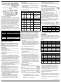
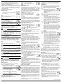
352-00021-004 Rev B
COMPRESSOR PROTECTION
The thermostat provides a 4-minute delay after shutting
off the heating or cooling system before it can be restarted.
This feature will prevent damage to your compressor
caused by rapid cycling. Note that this delay also applies
to the heating system control. It does not provide a delay
when there are power outages. You can select the function
on or off at the configuration.
Programmable Thermostat
TEMPERATURE RANGE
Owners Manual
Model: RS3210 Series
This thermostat can be programmed between 45ºF and
95ºF (7ºC and 35ºC). However, it will display room temperatures from 30ºF to 99ºF (0ºC and 37ºC). HI will be displayed
if the temperature is higher than 99ºF (37ºC), and LO will be
displayed if the temperature is lower than 30ºF (0ºC).This
thermostat will automatically shut down in Heat mode if the
temperature rises above 95ºF (35ºC), and automatically shut
down in Cool mode if the temperature drops below 45ºF
(7ºC).
NOTE: If the thermostat measures a temperature over
99ºF(37º), HI will be displayed on the LCD. If the temperature is below 32ºF(0º). and LO will be displayed on the LCD.
POWER FAILURE
Whenever the main power is interrupted or fails, the backup
battery power will maintain the current time. This thermostat also contains permanent memory that will retain your
program setting through power outages.
FEATURES
POWER SUPPLY
The thermostat is powered by 24 VAC and has battery
backup.
BATTERY WARNING
Structure of thermostat and explanation of the keypads
We are pleased you have selected our wall thermostat. Our
products are manufactured to high quality standards and
are designed for years of service.
Read This Before Installing Thermostat
OPERATION
YOUR THERMOSTAT FUNCTIONS WITH
Description
Fresh alkaline batteries should provide about one year
of service. When the batteries become weak, BATT will
alternate on the display with the current time. When this
message occurs, install 2 new AA batteries. You have
approximately 1 minute to change the batteries and keep
the thermostat’s clock and program settings. Once the
batteries have become too weak to ensure proper
operation, your system will be turned off, and the display
will be cleared except for BATT flashing on the LCD display.
6. Push excess wire into wall and plug hole with a fire
resistant material (such as fiberglass insulation) to prevent drafts from affecting thermostat operation.
Yes
Two Stage Heat & One Stage Cool
Yes
Standard Heat Only Systems
Yes
Millivolt Heat Only Systems – Floor or Wall Furnaces
Yes
Standard Central Air Conditioning
Yes
Gas or Oil Heat
Yes
• Slotted screwdriver(s) • Small Phillips screwdriver •
Hammer • Electric drill and 3/16” bit • Two1.5V (AA) size
alkaline batteries (included)
Electric Furnace
Yes
CAUTION:
Hydronic (Hot Water) Zone Heat-2 Wires
Yes
Hydronic (Hot Water) Zone Heat–3 Wires
No
To prevent electrical shock and/or equipment damage,
disconnect electric power to system at main fuse or circuit breaker box until installation is
complete.
Before removing wires from old thermostat, label each wire
with the terminal
designation it was removed from.
1. Shut off electricity at the main fuse box until installation
is complete. Ensure that electrical power is
disconnected.
2. Remove old thermostat: A standard heat/cool
thermostat consists of three basic parts:
All programming is normally performed at your thermostats
location.
a. The cover, which may be either a snap-on or hinge
type.
ARMCHAIR PROGRAMMING
b. The base, which is removed by loosening all screws.
You can program your thermostat before installation by
inserting the batteries and following the instructions starting
with the installer/configuration menu. This can be done
while you relax in your favorite chair and is a very good
way to familiarize yourself with all the functions of your
thermostat.
c. The switching subbase, which is removed by
unscrewing the mounting screws that hold it on
the wall or adapter plate.
The following time and temperature settings are
pre-programmed into the thermostat:
3. Remove the front cover of the old thermostat. With wires
still attached, remove wallplate from the wall. If the old
thermostat has a wall mounting plate, remove the
thermostat and the wall mounting plate as an assembly.
4. Identify each wire attached to the old thermostat.
Time
Heat
Cool
1
6:00 am
68ºF(20ºC)
78ºF(26ºC)
5. Disconnect the wires from the old thermostat one at a
time.
DO NOT LET WIRES FALL BACK INTO THE WALL.
2
8:00 am
60ºF(16ºC)
85ºF(29ºC)
6. Install new thermostat using the following procedures.
3
4:00 pm
68ºF(20ºC)
78ºF(26ºC)
WARNING
4
10:00 pm
60ºF(16ºC)
82ºF(28ºC)
Do not use on circuits exceeding specified voltage. Higher
voltage will damage control and could cause a shock or fire
hazard. Do not short out terminals on gas valve or primary
control to test. Incorrect wiring will damage thermostat and
could cause personal injury and/or property damage.
Temperature in Fº (Cº)
3. Place base over hole in wall and mark mounting hole
locations on wall using base as a template.
This thermostat includes two #8 slotted screws and two
wall anchors for mounting. To install your thermostat, you
should have the following tools and materials.
What You Need:
Standard Heat & Cooling Systems
INSTALLATION
1. Remove the packing material from the thermostat. Gently
pull the cover straight off the base. Forcing or prying on
the thermostat will cause damage to the unit.
5. Fasten base loosely to wall, as shown in Figure 1, using
two mounting screws. Place a level against bottom of
base, adjust until level, and then tighten screws. (Leveling
is for appearance only and will not affect thermostat
operation.) If you are using existing mounting holes, or if
holes drilled are too large and do not allow you to tighten
base snugly, use plastic screw anchors to secure subbase.
INSTALLATION
REMOVE THE MYLAR LABEL FROM THE LCD DISPLAY
WINDOW.
Attach Thermostat Base to Wall
4. Move base out of the way. Drill mounting holes.
Yes
Read the entire installation section of this Owner’s Manual
thoroughly before you begin to install or operate your
thermostat.
All wiring diagrams are for typical systems only. Refer to
equipment manufacturer’s instructions for specific system
wiring information.
NOTE: If you plan to be away from the premises over
30 days, we recommend that you replace the old
batteries with new alkaline batteries prior to leaving.
Yes
IMPORTANT
This thermostat is configured from the factory to operate a
heat/cool, fossil fuel (gas, oil, etc.), forced air system. It is
configured correctly for any system that DOES NOT require
the thermostat to energize the fan on a call for heat. If your
system is an electric heat or heat-pump system that
requires the thermostat to turn on the fan on a call for heat,
locate the ELEC/GAS switch on the back of the thermostat
(see Figure 1) and switch it to the ELEC position. This will
allow the thermostat to energize the fan immediately on
a call for heat. If you are unsure if the heating/cooling
system requires the thermostat to control the fan, contact a
qualified heating and air conditioning service person. When
the thermostat is configured for heat pump, the thermostat
will always power the circulator fan on a call for heat in the
Heat mode. The ELEC/GAS switch must be set to match
the type of auxiliary heat your system uses for proper
operation in the Emergency mode.
2. Connect wires beneath terminal screws on base using
appropriate wiring schematic (see Figures. 2 through 6).
Heat Pump (With Auxiliary or Emergency Heat)
This Thermostat will NOT control 110/220 Volt systems.
Figure 1. Electric/Gas Switch (Fan Option)
CAUTION: Once the BATT display occurs, the thermostat
is shut down, and your system will no longer
operate. In this condition, there is no temperature
control. NOTE: The backlight will not function
when the thermostat is in low battery condition.
Heat Pump (No Auxiliary or Emergency Heat)
Program Number
Selector Switches
Figure 2. Thermostat base
Figure 3. Typical wiring diagram for single transformer
heat pump systems
Figure 4. Typical wiring diagram for two transformer
heat pump systems with NO safety circuits
Figure 5. Typical wiring diagram for two transformer
heat pump systems with safety circuits in BOTH
systems
Cooling System
• Tap DAY to advance one day at a time.
1. Move System switch to select the Cool mode.
2. Press to adjust thermostat setting below room temperature. The blower should come on immediately on high
speed, followed by cold air circulation. The display
should show STG1.
3. Press to adjust the temperature setting above room temperature. The cooling system should stop operating.
• When finished press HOLD/RUN to return to normal
mode. After 15 seconds, the thermostat will return to normal automatically.
CONFIGURATION MENU
INSTALLER/CONFIGURATION MENU
Step
Figure 6. Typical wiring diagram for single
transformer multi-stage systems
Press
Button
Displayed
(Factory
Default)
Use the terminal output information below to help you wire
the thermostat properly for your heat pump system. After
wiring, see CONFIGURATION section for proper thermostat
configuration.
THERMOSTAT TERMINALS (HEAT PUMP)
SYSTEM
Heat Pump 1
L
Malfunction
C*
24 Volt (common)
R
24 Volt Emergency (hot)
E/W1
Emergency Mode 1st stage
W2
HP 1 and Emergency 2nd stage
Y1
Heat and Cool mode 1st stage (compressor)
G
Blower/Fan Energized on call for Heat and Cool
Set GAS/ELEC switch for Emergency mode
O
Energized in Cool Mode
B
Energized in Heat Emergency mode
Comments
Selects Single stage,
Multi-stage or Heat
SS1, HP2,
Pump (Single stage or
HP1
2-stage) System
Configuration
MS 2
2
F
(DIFF)2
1,3
DIFF (one stage)
3
F
(BLIT)on
off
BackLight
4
F
(SP2)2
1,3
DIFF (Two Stage)
5
F
(TEMP)F
C
Selects temperature
display °F or °C
• Press once. During Auto Programming,
the display will change as shown.
6
F
HOUR(12)
24
Selects time format
display 12 hours or
24 hours
• The thermostat will be programmed for
all 7 days of the week as shown below.
7
F
COMP(OFF)
ON
Selects Compressor
Lockout OFF or ON
1,2
Select 1 to reset to
factory defaults
8
F
FACT(0)
The configuration menu allows you to set certain thermostat
operating characteristics to your system or personal
requirements. Set System switch to OFF, then simultaneously press up and down keys to enter configuration menu.
The display will show the first item in the configuration
menu. The configuration menu table summarizes the configuration options. An explanation of each option follows.
Press F key to change to the next menu item. To exit the
menu and return to the program operation, press Hold/Run
key. If no keys are pressed within fifteen seconds, the
thermostat will revert to normal operation.
Note:
To prevent static discharge problems, touch side of
thermostat to release static build-up before touching
any keys.
If at any time during testing your system does not
operate properly, contact a qualified service person.
Fan Operation
2) Fast or slow cycle selection (one stage)
If your system does not have a G terminal connection, skip
to Heating System.
1. Turn on power to system.
2. Move Fan switch to ON position. The blower should
begin to operate.
3. Move Fan switch to AUTO position. The blower should
stop immediately
Heating System
1. Move System switch to Heat mode. If the auxiliary
heating system has a standing pilot, be sure to light it.
2. Press to adjust thermostat setting to 1ºF/1°C above room
temperature. The heating system should begin to operate. The display should show STG1. However, if the setpoint temperature display is flashing, the compressor
lockout feature is operating (see Configuration Menu,
item 5).
3. Adjust temperature setting to 3ºF/3°C above room temperature. If your system configuration is set at MS2, HP2
or HP1, the auxiliary heat system should begin to operate
and the display should show STG1+2.
4. Press to adjust the thermostat below room temperature.
The heating system should stop operating.
Emergency System
EMER bypasses the heat pump to use the heat source
wired to terminal E on the thermostat. EMER is typically
used when compressor operation is not desired, or you
prefer back-up heat only.
1. Press System switch to select Heat mode. then press
EMER key. EMER will show on the display.
2. Press to adjust thermostat setting above room temperature. The auxiliary heating system will begin to operate.
The display will show STG1 EMER to indicate that the
auxiliary system is operating.
3. Adjust temperature setting to 2ºF/2°C above room
temperature. The auxiliary heat system should begin
to operate and the display should show STG1+2.
4. Press to adjust the thermostat below room temperature.
The auxiliary heating system should stop operating.
Your thermostat is capable of holding up to
4 separate programs for each day of the week.
You can program all weekdays, Monday to
Friday, to the same 4 programs as shown in the table,
or each weekday can have a different set of 4 programs.
Similarly weekend programs, (Saturday and Sunday) can
be the same 4 programs or each weekend day can have
a different set of 4 programs.
F
1) Single Stage, Multi-stage or Heat Pump System
Configuration
This control can be configured for Heat Pump or two
stage heat/one stage cool multi-stage operation. The
display indicates MS 2 (default for multi-stage mode) in
the display. The multi-stage configuration can be toggled
to SS1, or HP1 by pressing the up or down key. In
multi-stage configuration, EMER mode is not used.
In this model, the HP2 is not used.
CHECK THERMOSTAT OPERATION
Studies conducted by the Department of Energy
estimate that setting your thermostat back 10ºF
(6°C) for two 8-hour periods during winter can
reduce your fuel bill by as much as much as
33%. Setting your thermostat up 5ºF (3°C) for
two 8-hour periods during summer can reduce
your fuel bill up to 25%.
1
Heat Pump Terminal Outputs
Refer to equipment manufacturer’s instructions for specific
system wiring information. You can configure the thermostat
for use with the following heat pump system types: HEAT
PUMP TYPE 1 1. Single stage compressor system; gas or
electric backup. This thermostat is designed to operate a
single-transformer system. If you have a two-transformer
system, cut and tape off one transformer. If transformer
safety circuits are in only one of the systems, remove the
transformer of the system with NO safety circuits. If
required, replace remaining transformer with a 75VA Class II
transformer. After disconnecting one transformer, the two
commons must be jumpered together.
Press
down key
to select
Auto Programming
3) Select backlight function OFF or on
Your thermostat is pre-programmed to meet the ENERGY
STAR™ guidelines for energy efficiency. Note that it is
easier to modify these programs than to program the
thermostat manually.
Temperature in Fº (Cº)
Program Number
6) Selects time format to display in 12-hour or 24-hour
clock
7) Select compressor lockout (COMP OFF or ON)
Selecting COMP ON will cause the thermostat to wait 4
minutes before turning on the compressor if the heating
and cooling system loses power. It will also wait 5 minutes minimum between cooling and heating cycles. This
is intended to help protect the compressor from short
cycling. Some newer compressors already have a time
delay built in and do not require this feature. Your compressor manufacturer can tell you if the lockout feature
is already present in their system. When the thermostat
compressor time delay occurs it will flash the setpoint
for about four minutes.
Heat
Cool
1
6:00 am
68ºF(20ºC)
78ºF(26ºC)
2
8:00 am
60ºF(16ºC)
85ºF(29ºC)
3
4:00 pm
68ºF(20ºC)
78ºF(26ºC)
4
10:00 pm
60ºF(16ºC)
85ºF(28ºC)
• Refer to Manual Programming for entering or changing
the programs.
PROGRAMMING
Before programming or changing programs, use this
Personal Program Schedule to determine which times and
temperature settings will best satisfy both your comfort and
energy saving requirements. Use a pencil so you can revise
yours records each time you change your temperature
settings.
Heating
DAY
Mon
Tue
Wed
Thu
Fri
Sat
4) Fast or slow cycle selection (two stage)
5) Select °F or °C readout. When you change this parameter, the programming returns to default. You have to set
the program again.
Time
Sun
Program 1
Time
Temp
Time
Temp
Time
Temp
Time
Temp
Time
Temp
Time
Temp
Time
Temp
Program 2
Time
Temp
Time
Temp
Time
Temp
Time
Temp
Time
Temp
Time
Temp
Time
Temp
Program 3
Time
Temp
Time
Temp
Time
Temp
Time
Temp
Time
Temp
Time
Temp
Time
Temp
Program 4
Time
Temp
Time
Temp
Time
Temp
Time
Temp
Time
Temp
Time
Temp
Time
Temp
Cooling
DAY
Mon
Tue
Wed
Thu
Fri
Sat
Sun
8) Select 1 to reset to factory defaults.
Manual Programming
Setting Time And Day
• Your thermostat can be programmed for weekdays and
weekends. Use Weekday/Weekend Programs to enter
or revise programs to match your Personal Program
Schedule. The same steps are used when entering
programs for the first time or revising programs entered
during Auto Programming.
Remove the mylar label covering the LCD
display window before operating thermostat.
• Initial display after power-up. The temperature will update after a few seconds.
• During Time and Day Setting mode, the
temperature and program display will go
blank.
• Press and hold HOUR to rapid advance
to the current hour. Tap to advance one hour at a
time. Note the AM/PM indicator, as the display will
cycle through 24 hours.
• Press and hold MIN to rapid advance to the current
minute.
• Tap to advance one minute at a time.
• Familiarize yourself with Manual Programming, so that
you can easily modify your programs as your comfort
needs change. The example below demonstrates the
Manual Programming method.
NOTE:
1. The program time can be set in 10-minute increments,
and remains the same for both Heat and Cool programs.
2. The program temperature can be set in increments of 1ºF
(1ºC).
3. The heat setpoint cannot be set higher than the cool
setpoint, and the cool setpoint cannot be set lower than
the heat setpoint.
352-00021-004 Rev B 5/08
4. If the system selector is in AUTO mode, the current
operating mode will be used for programming.
5. After 15 seconds without a key press, the thermostat
will return to normal display mode.
6. When setting the program time, note the AM/PM indicator.
7. With the Auto Recovery feature enabled, you do not need
to set your comfort program times early. Auto Recovery
will turn your system on so that the room is comfortable
at the program time.
Weekday/Weekend Programming
Weekday Programs
Display Reads
• Normal display of time, temperature, and
day of the week.
• Selects days Mon. to Fri. for same set
of 4 programs each day.
Step 3
The System Selector switch on the front of the
thermostat determines the operating mode of
the thermostat. You may select COOL, OFF,
HEAT, or AUTO. In order to take full advantage
of this thermostat’s features, we recommend using
the AUTO mode. Refer to the Auto Season Changeover
information for using this feature.
Temporary Manual Override
• Press and hold until 6:00 is displayed.
• Note AM/PM
To temporarily change the current set
temperature without affecting your program:
Step 4
• Press once to change temperature to 69ºF.
• Weekday program 1 is complete.
• Press PROG to move to program 2, 3, and 4
and follow the same steps.
to insert or change time and
temperature of other programs.
• Press and hold
or
for less than 1
second to enter Manual Override mode.
• Press
and
temperature.
to change to your desired new
• Press to RUN to normal mode or wait 15 seconds
for it to return automatically.
• The current program number will flash to signify
the Temporary Override.
• Selects weekend days Sat. and Sun.
for same set of 4 programs each
weekend day.
• Follow steps 2-4 to enter programs.
At the next program change, the Temporary Override is
canceled, and the next program temperature becomes the
setpoint temperature.
Similar to weekday programming.
to insert weekend programs.
Individual Day Programming
To program each individual day separately by a differnet
set of programs, first select day by displaying the day of
program, then insert the desired times and temperatures.
Display
Reads
• Mon. to Fri. are selected. Mon. to Fri.
will have same programs.
• Sat. to Sun. will have same programs.
• Mon. is seleted, program for Mon. only.
Use
System Selector Switch
The Fan switch should normally be set in the AUTO position.
The fan will be turned on along with normal operation of
your system. In a normal gas or oil furnace, the fan will
be turned on by your furnace after its warm-up delay. For
electric heat, air conditioning, and heat pump operation, the
fan will turn on with the system. To run the fan continuously,
slide the Fan switch to the ON position.
• Program indicator (1) is displayed.
• 68ºF is displayed.
• Mon. to Fri. is displayed.
Press
OPERATION
Fan Switch
Step 2
Use
• Set temperature is shown above
current room temperature.
NOTE: Anytime you install or remove the
thermostat from the wallplate, slide the
System Selector to the OFF position to
prevent the possibility of a rapid system
on-off.
Step 1
Use
• Press less than 1 second.
to enter programs for Monday.
Similarly • Tue. to Sun. can be selected.
Display the day to be programmed and use
to enter programs.
NOTE: Another approach to programming is to first
program all weekdays Mon. through Fri. and Sat. and
Sun. as same programs. Then, display and change the
programs of only those days which willhave different
programs.
Reviewing Programs
You may want to review the programs to see that the
settings are compatible with your lifestyle.
• Normal display of current time, day of week
temperature, and day of week.
• 1st weekday program is displayed.
• Program indicator (1) appears.
• Mon to Fri indication appears.
• Continue pressing
to view each day.
• Continue pressing
to view each period.
If you are armchair programming the thermostat, turn the
System Selector to the OFF position
Reviewing the Current Temperature Setting
Current time and temperature.
To end the Temporary Manual Override:
• Press and wait for HOLD to display on the LCD.
• Press HOLD key twice. This will return the set
temperature to the current program set temperature.
NOTE: The Auto Season Changeover feature will not operate
while the thermostat is in Temporary Manual Override.
Refer to the Auto Season Changeover feature for more
information.
Permanent Override or a Designated Day Override
To hold your Manual Override for vacation or until a
Designated Day.
• Press to make the current program temperature the HOLD temperature. HOLD
will be displayed on the LCD, and the
program number will disappear.
• Follow the Temporary Manual Override instructions
above to change the Permanent Manual Override
temperature.
• You can confirm the setpoint by pressing HOLD/RUN
for less than 1 second.
• Press again. Hold day will be displayed on the LCD
and the clock will disappear
• Press Day key to add override days. Press Hour key
to reduce override days.
• Follow the Temporary/Designated Day
Override instructions above to change
the Permanent Manual Override
temperature.
To End Override:
Under Permanent Override press hold/return key twice.
Under a Designated Day Override press the hold once. The
thermostat will return to the current program, and the HOLD
display will be canceled.
NOTE: The Auto Season Changeover feature will not operate
while the thermostat is in permanent Manual Override. Refer
to the Auto Season Changeover
feature for more information.
Auto Season Changeover
When the System Selector is in AUTO position, the thermostat will automatically change between heating and cooling
systems, depending on your program. We recommend keeping your programmed heating and cooling temperature at
least 4ºF (2ºC) apart to allow the Auto Season Changeover
to occur when the appropriate temperature span has been
reached. If your heating and cooling programs have setpoints that are close, there is a built-in program to prevent
the thermostat from going into Temporary, Designated Day
Override, or Permanent Override, as these overrides are
energy saving settings. Auto Season Changeover will still
function in Home Today mode, as this is a comfort setting.
For example, you may have the following temperatures programmed at a given time: Heat Set Temp=68ºF, Cool Set
Temp=78ºF.
If the room temperature rises above 78ºF, then the thermostat will automatically change to cool mode and turn on the
air conditioner.
Likewise, the thermostat will automatically change to heat
mode and turn on heat when the room temperature falls
below 68ºF.
HOME TODAY
This feature allows you to quickly and temporarily override
your energy saving program setting on days when you are
normally away from home with one key press.
• Press to enter the Home Today override.
When in Home Today override, the
thermostat will use the previous manual
override temperature setpoint for the
remainder of the day.
• The display will alternate between HOME and the
current time.
• When pressed during the day, the thermostat will
remain in Home Today mode until the first program
of the next day.
• If the system is changed between Heat and Cool
modes (either manually or by Auto Season
Changeover) during the Home Today Override period,
the setpoint temperature will be automatically
update. It will automatically change from the lowest
cool program setpoint to the highest heat program
setpoint.
• Press to exit Home Today mode before the schedule
ending time. HOME is no longer displayed on the
LCD screen, and the thermostat returns to the
current program.
• You can manually change the setpoint temperature
while in Home Today mode. Refer to the Temporary
Manual Override instructions. Manually changing the
set temperature while in Home Today mode will not
affect the Home Today ending time, however, the set
temperature will not change automatically with a
manual or automatic change between heating and
cooling.
Energy Monitor
• The Energy monitor feature measures
and stores the amount of time the heating and air conditioning system operates. Usage can be displayed for Today
(since 12 am), Yesterday, This Week (since Monday),
Last Week (last Monday through Sunday), and Total
(up to 999 Hrs). By monitoring your energy usage,
you see how much the setback periods are saving,
and you can test program adjustment to save even
more. To review energy usage, press to cycle
through Today, Yesterday, This Week, Last Week,
and Total. Press again to return to normal mode, or
wait 15 seconds for the display to return to normal
mode. You can also return to normal mode at any
time by pressing RUN.
• For example: This LCD display shows Today’s
usage to be 10 Hours, 26 minutes.
• Press and hold for 3 seconds to reset the Energy
Monitor’s counters.
The display will blink, and counters will be cleared
to zero.
NOTE: Clearing the Energy Monitor counter will also clear
the Filter Monitor counter, as Filter usage and Total Energy
usage are the same. Also, clearing the Filter Monitor counter
will clear ALL Energy Monitor counters as well.
Filter Monitor
Your thermostat also keeps a record of the
number of hours your filter has been in use. To
maximize your system’s performance and energy
efficiency, change or clean your filter regularly.
• When the total system run time for heat and
cool reaches 500 hours, you need to clean or
change your system’s filter. FILT will continue
to flash until the counter is set back to zero.
• Press FILTER to review total filter usage. The display will
blink FILT, then show the Filter Monitor counter. After 15
seconds, the display will return to normal mode, or you
can hit RUN to exit immediately.
The Filter Monitor will display up to 999 hours and 59
minutes of usage.
• To reset the Filter Monitor counter, depress FILTER for
3 seconds. The display will blink, and the counter will be
reset to zero.
NOTE: Clearing the Filter Monitor counter will also clear ALL
Energy Monitor counters, as Filter usage and Total Energy
usage are the same. Also, clearing the Energy Monitor
counters will clear the Filter Monitor counter as well.
Auto Recovery
Auto Recovery calculates how early to turn your
system back on, so that the room temperature is
already comfortable by the start of the program
period. Auto Recovery works in both Heat and
Cool modes.
• When the thermostat is in Auto Recovery mode, the
display will alternate RECO with time, and the program
indicator will flash.
352-00021-004 Rev B 5/08
• Auto Recovery can be disabled by sliding the Recovery
switch on the circuit board to disable.
• Auto Recovery will not operate if Permanent Hold or
Temporary Hold is in operation.
• Auto Recovery can be canceled manually if HOLD is
pressed during the recovery process. If a recovery
process is canceled manually then the recovery process
will not start again until the next program period starts
(an exception is that if time or program is changed then
the thermostat will check Auto Recovery conditions
immediately).
• Auto Recovery will be canceled and change to next
period.
• Auto Recovery will be canceled and change to Home
Today mode if HOME TODAY is pressed during the
recovery process.
TROUBLESHOOTING
Problem
Solution
SCRAMBLED OR
DOUBLE DISPLAY
(numbers over numbers)
1. Remove clear mylar sticker.
NO DISPLAY
1. Check battery connections and batteries.
2. Press the reset button once with a small pin
and hold for two seconds then reprogram.
ENTIRE DISPLAY DIMS
1. Replace batteries.
PROGRAM DOES NOT
CHANGE AT YOUR
DESIRED SETTINGS
1. Check that the time is set properly to AM or
PM.
2. Check that the thermostat is not in HOLD
or Home Today mode.
3. Check for the correct day settings.
AUTO/FAN DOES NOT
TURN ON
1. Move Elec/Gas selector to opposite position.
2. The thermostat may be in Auto mode. Look
for AUTO on the LCD display. If the heat or
cool program temperatures are close, the
thermostat requires a larger temperature
change before switching systems.
3. There may be as much as 4 minute delay
before the heat or cool system turns on. Wait
and check. (Compressor protection delay)
4. Check your circuit breakers and switches to
ensure there is power to the system.
5. Replace batteries.
6. Make sure your furnace blower door is closed
properly.
7. Check the position of the Furnace or Heat
Pump selector switches: Normal/O/B.
ERRATIC DISPLAY
1. Press the reset button once with a small pin
and hold for two seconds then reprogram.
UNIT CONTINUES TO
OPERATE IN THE OFF
POSITION
1. Replace unit.
THERMOSTAT
PERMANENTLY READS E1,
E2, E3, E4
1. Replace unit.
Keyboard lock
The keyboard can be locked to prevent
unauthorized changes to the thermostat.
To lock or unlock the keyboard, press and hold
hold/run key for 3 seconds. The keyboard is locked
when LOCK appears on the display.
• When all keys are locked, LOCK will appear on the
display for 1 second any time a key is pressed.
Backlighting
Your thermostat has an electroluminescent lamp that
backlights the display for easy viewing in the dark. When
any key is pressed the display is illuminated.
The display will remain illuminated for 8 seconds after the
last key is pressed. This allows the light to stay on if you
need to operate several keys.
NOTE: If the thermostat is in Low Battery warning
condition, the backlight will not operate. Replace with 2
new AA alkaline batteries to restore the Backlight function.
If you experience any other problems, contact Technical Support at:
www.invensyscontrols.com or (800) 445-8299
Low Battery Warning
Your thermostat has a two-stage lower battery
warning system. When the batteries are first
detected to be weak, the first stage low battery
warning is indicated by BATT flashing on the
LCD display. Replace the batteries with 2 new
AA alkaline batteries.
When the batteries become too weak for normal operation,
the thermostat enters the second stage low battery warning
which shuts down the thermostat. In this condition, BATT
flashes alone on the display, and the thermostat will turn
your system off. Your system will remain off until the
batteries are replaced.
NOTE: The thermostat will still keep the current Set
Temperature and Filter run time in memory until new
batteries are installed. After confirming that new batteries
have been inserted, the thermostat will return to normal
operation.
Error Mode
If the thermostat is unable to control your
system due to an unexpected battery problem,
the thermostat will enter Error Mode. In this
condition, the thermostat flashes E1, E2, E3
or E4 on the LCD display, and shuts off your
system. To correct this problem, replace the
batteries with 2 new AA alkaline batteries, even
if you have recently replaced them. Press the reset
button once with a small pin and hold for two seconds
then reprogram.
If Error Mode returns, please contact us for further
information.
Warning Mode
If the Malfunction Input (L) from the heat pump
is active, the thermostat flashes E5on the LCD
display.
Auto Cut Off
Your thermostat will automatically shut down in Heat mode
if the room temperature rises above 95ºF (35ºC). It will shut
down in Cool mode if the room temperature drops below
40ºF (4ºC).
Two Year Limited Warranty
Invensys Controls warrants to the original contractor installer
or to the original consumer user that each new Robertshaw
Product shall be free from defects in materials and workmanship under normal use and service for a period of two (2)
years from the date of manufacture (“Warranty Period”).
If any Product fails within the applicable Warranty Period,
Invensys Controls shall, at its sole option, repair or replace
the Product, provided that the Product is returned to
Invensys Controls’ facility or designated agent within the
Warranty Period, with transportation charges prepaid, and
that the Product, upon examination by Invensys Controls, is
found to conform to this warranty. The above warranty does
not apply to: i) batteries; ii) improper installation; iii) Products
that have been damaged, misused, neglected, mishandled,
or altered in any manner whatsoever, and/or; iv) defects or
damage that result from use of the Product in other than its
normal and customary manner or in any manner not in
accordance with Invensys Controls’ recommendations
and/or instructions. Any and all costs of labor, thermostat
removal, or reinstallation are not covered under this warranty
and shall be the sole responsibility of the consumer or
installer, as applicable.
THE FOREGOING WARRANTY IS IN LIEU OF AND
EXCLUDES ALL OTHER WARRANTIES, WHETHER VERBAL
OR WRITTEN, EXPRESS OR IMPLIED INCLUDING, EXCEPT
TO THE EXTENT PROHIBITED BY APPLICABLE LAW, THE
IMPLIED WARRANTIES OF MERCHANTABILITY AND
FITNESS FOR A PARTICULAR PURPOSE. IN NO EVENT
SHALL INVENSYS CONTROLS BE LIABLE TO CONSUMER,
CONTRACTOR OR ANY THIRD PARTY FOR ANY
CONSEQUENTIAL, INCIDENTIAL, SPECIAL OR PUNITIVE
DAMAGES ARISING FROM OR RELATING TO USE OF THE
PRODUCT INCLUDING, BUT NOT LIMITED TO, LOSS OF
GOODWILL, LOSS OF PROFIT OR REVENUE, AND
PROPERTY DAMAGE, REGARDLESS WHETHER SUCH
LOSS OR DAMAGE IS BASED IN CONTRACT, WARRANTY,
TORT, NEGLIGENCE, STRICT LIABILITY, INDEMNITY,
PRODUCT LIABILITY, OR OTHERWISE AND EVEN IF
INVENSYS CONTROLS HAS BEEN ADVISED OF THE
POSSIBILITY OF SUCH DAMAGES.
Note that if your system has malfunctioned and no longer
responds to thermostat controls, the Auto Cut-Off will have
no effect.
191 E. North Avenue
Carol Stream, Illinois 60188
www.invensyscontrols.com
©2008 Invensys Controls
352-00021-004 Rev B 5/08