1
Diesel Injection Pump
SERVICE MANUAL
OPEL Z17DT TYPE ENGINE
COMMON RAIL SYSTEM (CRS)
OPERATION
January, 2007
00400588E
© 2006 DENSO CORPORATION
All Rights Reserved. This book may not be reproduced
or copied, in whole or in part, without the written
permission of the publisher.
Table of Contents
Table of Contents
Operation Section
1. PRODUCT APPLICATION INFORMATION
1.1
Outline . . . . . . . . . . . . . . . . . . . . . . . . . . . . . . . . . . . . . . . . . . . . . . . . . . . . . . . . . . . . . . . . . . . . . . . . . . . . . . . . 1-1
1.2
Application . . . . . . . . . . . . . . . . . . . . . . . . . . . . . . . . . . . . . . . . . . . . . . . . . . . . . . . . . . . . . . . . . . . . . . . . . . . . . 1-1
1.3
System Component Part Numbers . . . . . . . . . . . . . . . . . . . . . . . . . . . . . . . . . . . . . . . . . . . . . . . . . . . . . . . . . . 1-1
2. SUPPLY PUMP
2.1
Outline . . . . . . . . . . . . . . . . . . . . . . . . . . . . . . . . . . . . . . . . . . . . . . . . . . . . . . . . . . . . . . . . . . . . . . . . . . . . . . . . 1-2
2.2
Suction Control Valve (SCV) . . . . . . . . . . . . . . . . . . . . . . . . . . . . . . . . . . . . . . . . . . . . . . . . . . . . . . . . . . . . . . . 1-3
3. RAIL
3.1
Outline . . . . . . . . . . . . . . . . . . . . . . . . . . . . . . . . . . . . . . . . . . . . . . . . . . . . . . . . . . . . . . . . . . . . . . . . . . . . . . . . 1-5
4. INJECTOR
4.1
Outline . . . . . . . . . . . . . . . . . . . . . . . . . . . . . . . . . . . . . . . . . . . . . . . . . . . . . . . . . . . . . . . . . . . . . . . . . . . . . . . . 1-6
4.2
QR Code . . . . . . . . . . . . . . . . . . . . . . . . . . . . . . . . . . . . . . . . . . . . . . . . . . . . . . . . . . . . . . . . . . . . . . . . . . . . . . 1-7
5. CONTROL SYSTEM COMPONENTS DESCRIPTION
5.1
Outline . . . . . . . . . . . . . . . . . . . . . . . . . . . . . . . . . . . . . . . . . . . . . . . . . . . . . . . . . . . . . . . . . . . . . . . . . . . . . . . . 1-8
5.2
Engine ECU. . . . . . . . . . . . . . . . . . . . . . . . . . . . . . . . . . . . . . . . . . . . . . . . . . . . . . . . . . . . . . . . . . . . . . . . . . . . 1-8
5.3
Boost Pressure Sensor . . . . . . . . . . . . . . . . . . . . . . . . . . . . . . . . . . . . . . . . . . . . . . . . . . . . . . . . . . . . . . . . . . . 1-8
6. DIAGNOSIS
6.1
Diagnostic Trouble Code (DTC) Table. . . . . . . . . . . . . . . . . . . . . . . . . . . . . . . . . . . . . . . . . . . . . . . . . . . . . . . . 1-9
7. EXTERNAL WIRING DIAGRAM
7.1
Engine ECU External Wiring Diagram. . . . . . . . . . . . . . . . . . . . . . . . . . . . . . . . . . . . . . . . . . . . . . . . . . . . . . . 1-21
7.2
Engine ECU Connector Diagram. . . . . . . . . . . . . . . . . . . . . . . . . . . . . . . . . . . . . . . . . . . . . . . . . . . . . . . . . . . 1-23
Operation Section
1 1
1. PRODUCT APPLICATION INFORMATION
1.1 Outline
The Common Rail System (CRS) used with the OPEL Z17DT* engine has been redesigned. Basic system configuration
is identical to that of the CRS used with the OPEL 4EE2 engine. This service manual only addresses changes/additions
from the CRS used with the 4EE2 engine. For details on other parts, refer to the service manual entitled, "Common Rail
System for OPEL 4EE2 Type Engine" (Doc ID: 00400028).
1.2 Application
Model Year
Vehicle Name
Corsa
2007 MY
Meriva
Engine Model
Engine Displacement
Reference
Z17DT*
1.7L
Made in Europe
1.3 System Component Part Numbers
The EGR valve has been changed from a DENSO product to that of another manufacturer.
Vehicle Model
Part Name
DENSO Part Number
Car Manufacturer
Part Number
Corsa
Meriva
Supply Pump
Yes
Yes
HU294000-050#
97376269
Rail
Yes
Yes
HU095440-090#
97376271
Injector
Yes
Yes
HU095000-613#
97376270
Yes
No
MB275800-467#
98000820
No
Yes
MB275800-475#
98002896
No
Yes
MB275800-476#
98025828
Crankshaft Position Sensor
Yes
Yes
949979-120#
97321620
Cylinder Recognition Sensor
Yes
Yes
949979-120#
97321620
Boost Pressure Sensor
Yes
Yes
079800-783#
97381191
Engine ECU
DTR
DT
Operation Section
1 2
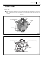
2. SUPPLY PUMP
2.1 Outline
This HP3 supply pump is equipped with a compact Suction Control Valve (SCV). Parts other than the SCV have not
changed. For details, refer to the service manual entitled, "Common Rail System for OPEL 4EE2 Type Engine" (Doc
ID: 00400028).
New Model
Old Model
1 3
Operation Section
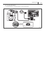
2.2 Suction Control Valve (SCV)
A linear solenoid type valve has been adopted. The ECU controls the duty ratio (the length of time that the current is
applied to the SCV), in order to control the quantity of fuel that is supplied to the high-pressure plunger.
Because only the quantity of fuel that is required for achieving the target rail pressure is drawn in, the drive load of the
supply pump decreases.
When current flows to the SCV, variable electromotive force is created in accordance with the duty ratio, moving the
armature to the left side. The armature moves the cylinder to the left side, changing the opening of the fuel passage and
thus regulating the fuel quantity.
With the SCV OFF, the return spring contracts, completely opening the fuel passage and supplying fuel to the plungers.
(Full quantity intake and full quantity discharge)
When the SCV is ON, the force of the return spring moves the cylinder to the right, closing the fuel passage (normally
opened).
By turning the SCV ON/OFF, fuel is supplied in an amount corresponding to the actuation duty ratio, and fuel is discharged by the plungers.
(1) Short duty ON duration
Short duty ON duration => large valve opening => maximum intake quantity
Operation Section
(2) Long duty ON duration
Long duty ON duration => small valve opening => minimum intake quantity
1 4
1 5
Operation Section
3. RAIL
3.1 Outline
The shape of the rail as well as the installation positions for the fuel pressure sensor and pressure limiter have been
changed. The shape and characteristics of the rail pressure sensor and pressure limiter have not changed. For details,
refer to the service manual entitled, "Common Rail System for OPEL 4EE2 Type Engine" (Doc ID: 00400028).
New Model
Old Model
Operation Section
1 6
4. INJECTOR
4.1 Outline
The shape of the injector as well as the QR code (ID code) correction point have been changed. Other specifications
and operations have not changed. For details, refer to the service manual entitled, "Common Rail System for OPEL
4EE2 Type Engine" (Doc ID: 00400028).
1 7
Operation Section
4.2 QR Code
QR code correction points are as per the figure below.
Operation Section
1 8
5. CONTROL SYSTEM COMPONENTS DESCRIPTION
5.1 Outline
Changes/additions to control-related parts are explained herein. For details on other parts, refer to the service manual
entitled, "Common Rail System for OPEL 4EE2 Type Engine" (Doc ID: 00400028).
5.2 Engine ECU
The shape of the engine ECU has been changed. As a result, the shape of the connector has also been changed. For
details on the connector, refer to "7. EXTERNAL WIRING DIAGRAM".
5.3 Boost Pressure Sensor
The boost pressure sensor detects intake air pressure. The boost pressure sensor also includes a thermistor-type temperature sensor.
Operation Section
1 9
6. DIAGNOSIS
6.1 Diagnostic Trouble Code (DTC) Table
Read symptom codes using the manufacturer's diagnostic tool.
(1) For Corsa
DTC
P0100
P0095
P0115
Failure Part
Mass airflow sensor
Intake air temperature sensor
Coolant temperature sensor
P1120
Accelerator position sensor 1
P1122
Accelerator position sensor 2
P1120
Accelerator position sensor
P0235
P0180
P0190
Boost pressure sensor
Fuel temperature sensor
Rail pressure sensor
Symptom
27
Mass airflow sensor signal too high
26
Mass airflow sensor signal too low
52
Mass airflow sensor performance invalid
07
Intake air temperature sensor signal too high
03
Intake air temperature sensor signal too low
07
Coolant temperature sensor signal too high
03
Coolant temperature sensor signal too low
52
Coolant temperature sensor performance invalid
07
Accelerator position sensor 1 signal too high
03
Accelerator position sensor 1 signal too low
07
Accelerator position sensor 2 signal too high
03
Accelerator position sensor 2 signal too low
52
EGR lift (position) sensor
P2226
Atmospheric pressure sensor
03
Boost pressure sensor signal too low
52
Boost pressure sensor performance invalid
07
Fuel temperature sensor signal too high
03
Fuel temperature sensor signal too low
07
Rail pressure sensor signal too high
03
Rail pressure sensor signal too low
Rail pressure sensor signal keeping the middle
range
07
EGR lift (position) sensor signal too high
03
EGR lift (position) sensor signal too low
07
Atmospheric pressure sensor signal too high
03
Atmospheric pressure sensor signal too low
Intake air temperature frequency sensor
26
Intake air temperature analog sensor
invalid
Boost pressure sensor signal too high
27
P0110
Accelerator position sensor signal performance
07
52
P0409
Failure Mode
01
02
Intake air temperature frequency sensor frequency
too long
Intake air temperature frequency sensor frequency
too short
Intake air temperature analog sensor signal too
high
Intake air temperature analog sensor signal too low
Operation Section
DTC
P0530
Failure Part
A/C pressure sensor
Symptom
Failure Mode
07
A/C pressure sensor signal too high
03
A/C pressure sensor signal too low
57
A/C pressure sensor GND signal open
Brake switch diagnostics; Cruise control brake
P0571
Brake switch
08
P0168
Fuel injection quantity reduction
5B
P0704
Clutch switch
08
P0520
Oil pressure switch
05
Oil pressure switch stuck open
P0335
Crankshaft position sensor
04
Crankshaft position sensor no pulse
08
Crankshaft position sensor signal invalid
P0340
Cylinder recognition sensor
04
Cylinder recognition sensor no pulse
08
Cylinder recognition sensor signal invalid
P0016
Crankshaft position sensor / Cylinder recognition sensor
P0685
P1625
08
02
Main relay
P0641
Sensor reference voltage 1
P0651
Sensor reference voltage 2
62
Crankshaft position sensor/cylinder recognition
sensor signal synchronization error
Main relay diagnostics; Main relay stuck closed
Main relay diagnostics; Main relay stuck open/relay
output open load
07
Sensor reference voltage output No.2 too high
03
Sensor reference voltage output No.2 too low
02
P0683
04
A/C relay output
sion only)
Sensor reference voltage output No.1 too low
Glow system
P0645
Clutch switch circuit malfunction (manual transmis-
03
06
P1625
Fuel quantity reduction by injector leak temperature
Sensor reference voltage output No.1 too high
P0380
Main relay
switch no signal
07
01
P0685
1 10
Glow controller command line short to battery; Glow
controller internal malfunction
Glow controller command line open load/short to
GND; Glow controller internal malfunction
Glow plug R side short; Glow diagnosis line short to
GND; Glow controller internal malfunction
Glow plug R side open load; Glow diagnosis line
open load; Glow controller internal malfunction
01
Main relay/relay output short to battery
63
Main relay/relay output short to GND
01
A/C relay output short to battery
06
A/C relay output open load/short to GND
EGR control DC motor output 1 short to battery/
08
P0403
short to GND output 2 short to battery/short to GND
motor short
EGR control DC motor
04
EGR control DC motor output 1 open load output 2
open load motor open load
Operation Section
1 11
DTC
Failure Part
Symptom
Failure Mode
P0201
61
TWV1 output open load; Injector #1 coil open
P0203
61
TWV2 output open load; injector #3 coil open
P0204
61
TWV3 output open load; injector #4 coil open
P0202
61
TWV4 output open load; injector #2 coil open
01
P2146
02
Injector drive
01
P2149
02
58
P0606
52
P0602
P062F
QR code failure
P0093
P0088
Common rail system
P0087
short to battery, both TWV 1 and TWV 3 open load
COM 1 output short to GND; TWV 1 or 3 output
short to GND
COM1 output short to battery; TWV 2 or 4 output
short to battery, both TWV 2 and TWV 4 open load
COM 2 output short to GND; TWV 2 or 4 output
short to GND
Capacitor charge-up circuit malfunction (insufficient
charge)
Capacitor charge-up circuit malfunction (excessive
charge)
48
QR code not programmed
33
QR code error
36
QR correction information is abnormal
66
Pressure limiter activated
52
Supply pump protection
68
Supply pump exchange
66
Supply pump malfunction (insufficient flow)
01
P0001
COM1 output short to battery; TWV 1 or 3 output
Suction control valve (SCV)
SCV (+) output short to battery; SCV (-) output
short to battery
SCV (+) output open load/short to GND; SCV (-)
06
output open load/short to GND; SCV coil open;
SCV coil short
SCV valve
P0094
Common rail system
P0088
61
66
SCV stuck
Rail pressure sensor performance invalid included
fuel leak
5B
Rail pressure exceeds upper limit
P0217
Engine overheat
5B
Engine overheat
P0219
Engine overrun
5B
Engine overrun
4A
Check sum error - flash area
37
CPU fault; -Main CPU fault
38
CPU fault; -Watchdog IC fault
P0601
P0606
Engine ECU internal failure
P0301
Injector 1
04
Cylinder 1 fuel system failure
P0302
Injector 2
04
Cylinder 2 fuel system failure
P0303
Injector 3
04
Cylinder 3 fuel system failure
P0304
Injector 4
04
Cylinder 4 fuel system failure
Operation Section
DTC
P0400
Failure Part
P0234
P0243
P0660
EGR excessive flow (EGR positive deviation)
63
EGR insufficient flow (EGR negative deviation)
61
EGR valve open/close stuck
52
Turbo control system (negative deviation)
52
Turbo control system (positive deviation)
Electric Vacuum Regulating Valve (EVRV);
01
EVRV; Turbo output short to battery
Turbo
06
EVRV; Turbo output open load/short to GND
01
VSS output (VSV) short to battery
06
VSS output (VSV) open load/short to GND
Turbo system
Variable swirl control (VSS) output (VSV)
01
P0638
Diesel throttle system
P2620
06
08
07
P0425
Upper Oxygen catalyst temperature sensor
(exhaust gas temperature 1)
03
54
07
P042A
Upper DPF temperature sensor (exhaust
gas temperature 2)
03
54
P2452
Differential pressure sensor
P0480
Fan relay 1 output
P0481
Fan relay 2 output
P0482
Fan relay 3 output
P0100
Mass airflow sensor
P242F
P2002
P2452
Failure Mode
5B
EGR system
EGR valve
P0299
Symptom
1 12
DPF system
Diesel throttle controller output signal short to battery
Diesel throttle controller output signal open load/
short to GND
Diesel throttle controller failure status
Upper
oxygen
catalyst
temperature
Upper
oxygen
catalyst
temperature
sensor
(exhaust gas temperature 1) voltage too low
Upper
oxygen
catalyst
temperature
sensor
(exhaust gas temperature 1) temperature too high
Upper DPF temperature sensor (exhaust gas temperature 2) voltage too high
Upper DPF temperature sensor (exhaust gas temperature 2) voltage too low
Upper DPF temperature sensor (exhaust gas temperature 2) temperature too high
07
Voltage too high
03
Voltage too low
5B
Differential pressure too high
61
Hose line disconnect upstream
01
Fan control relay 1 short to battery
06
Fan control relay 1 open load/short to GND
01
Fan control relay 2 short to battery
06
Fan control relay 2 open load/short to GND
01
Fan control relay 3 short to battery
06
Fan control relay 3 open load/short to GND
28
Mass airflow sensor too low
66
DPF over loaded
5B
DPF over loaded 2
57
Not ended regeneration
52
sensor
(exhaust gas temperature 1) voltage too high
Differential pressure sensor characteristic abnormality
Operation Section
1 13
DTC
P0425
P042A
Failure Part
Upper Oxygen catalyst temperature sensor
(Exhaust gas temperature 1)
Upper DPF temperature sensor (exhaust
gas temperature 2)
P2425
EGR cooler bypass
P0400
EGR DC motor
Symptom
Upper
52
oxygen
catalyst
temperature
52
Upper DPF temperature sensor (exhaust gas temperature 2) characteristic abnormality
01
EGR cooler bypass output short to battery
06
EGR cooler bypass output open load/short to GND
62
EGR DC motor lock
Immobilizer 3 Control Unit (ICM3) function in ECU
is not programmed or is in function reset mode
4F
ICM3 function in ECU is switched off
00
Incorrect Security Code input
00
Response frame not received
00
Transmitted response was incorrect
50
Transmitted response was distorted ("0")
P1615
00
Failed power train identification
P1616
00
Failed environment identification
P1611
P1613
Immobilizer
P1614
Electronically Erasable and Programmable Read
P062F
DPF system
31
P0409
EGR valve
52
EGR lift sensor characteristic abnormality
00
Node error (Bus-off)
70
ABS General Frame receive is failed
U2103
U2108
CAN data error
U2107
70
U0418
71
72
U2108
U0418
P0650
U0405
Only Memory (EEPROM) failure
Body Control Module (BCM) General Frame
receive is failed
Brake pedal initial travel achieved validity invalid
Traction Control System (TRC) request torque Rolling Counter (RC) error
74
TRC request torque Protection value error
72
Brake pedal position RC error
Vehicle Integrated Function (VIF) related
diagnosis
sensor
(exhaust gas temperature 1) sensor characteristic
abnormality
00
P1610
Failure Mode
74
Brake pedal initial travel achieved protection value
error
70
Instrument panel virtual device unavailability
71
Cruise control switch invalid
72
Cruise control switch RC error
74
Cruise control switch protection value error
Operation Section
DTC
Failure Part
Symptom
44
47
P0602
U2101
Programming
P0621
P0622
Alternator F-terminal system
P0571
P1602
P062F
Brake switch signal error
Microinjection quantity learning (SQL)
Vehicle Identification
Number
(VIN)
not pro-
grammed
4A
Tire circumference not programmed
46
Subnet Configuration List (SCL) is not defined
4C
Engine identifier not programmed
00
Alternator L-terminal system
Security access not armed
Variant word not programmed
4D
P1600
Failure Mode
45
43
P1602
1 14
04
Rejected reprogramming attempt of a critical
engine identifier
Maximum Vehicle Speed (Vmax) limitation speed
not programmed
Engine ECU internal engine torque supervisions
Alternator L-terminal duty ratio too high (at Key-ON
test)
08
Alternator L-terminal duty ratio too low (at Run-test)
07
Alternator F-terminal ratio too high (at Key-ON test)
03
Alternator F-terminal ratio too low (at Run-test)
01
Permanently active (One or Both Brake error)
56
Brake switch sequence error {Brake Lamp Switch
(BLS) error}
4B
SQL value not programmed
34
SQL value error
P0299
Popping-off
5A
Variable Nozzle Turbo (VNT) hose popping off
P1602
Pump learning
4E
Pump learning incompletion
71
All wheel signals set to invalid by sender ABS
P0500
ABS
P0501
71
P1602
Programming
3B
P1602
Tuning protection
48
Failure Part
Symptom
Both non-driven wheel signals set to invalid by
sender ABS
Engine identifier in engine ECU calibration and
engine ECU-EEPROM are not matching
Illegal engine tuning protection
(2) For Meriva
DTC
P0100
P0095
P0115
Mass airflow sensor
Intake air temperature sensor
Coolant temperature sensor
Failure Mode
07
Mass airflow sensor signal too high
06
Mass airflow sensor signal too low
02
Mass airflow sensor performance invalid
07
Intake air temperature sensor signal too high
03
Intake air temperature sensor signal too low
07
Coolant temperature sensor signal too high
03
Coolant temperature sensor signal too low
02
Coolant temperature sensor performance invalid
Operation Section
1 15
DTC
Failure Part
P1120
Accelerator position sensor 1
P1122
Accelerator position sensor 2
P1120
Accelerator position sensor
P0235
P0180
P0190
Boost pressure sensor
Fuel temperature sensor
Rail pressure sensor
Symptom
07
Accelerator position sensor No.1 signal too high
03
Accelerator position sensor No.1 signal too low
07
Accelerator position sensor No.2 signal too high
03
Accelerator position sensor No.2 signal too low
08
EGR lift (position) sensor
P2226
Atmospheric pressure sensor
P0110
Intake air temperature frequency sensor
P0500
P0530
Vehicle speed sensor
A/C pressure sensor
Invalid
Boost pressure sensor signal too high
03
Boost pressure sensor signal too low
02
Boost pressure sensor performance invalid
07
Fuel temperature sensor signal too high
03
Fuel temperature sensor signal too low
07
Rail pressure sensor signal too high
03
Rail pressure sensor signal too low
Rail pressure sensor signal keeping the middle
range
07
EGR lift (position) sensor signal too high
03
EGR lift (position) sensor signal too low
07
Atmospheric pressure sensor too high
03
Atmospheric pressure sensor too low
07
Ambient temperature signal too high
06
Ambient temperature signal too low
01
Vehicle speed sensor frequency too high
06
Vehicle speed sensor input open/short
08
Vehicle speed sensor signal invalid
07
A/C pressure signal too high
03
A/C pressure signal too low
04
A/C pressure GND signal open
01
P1571
Accelerator position sensor signal performance
07
02
P0409
Failure Mode
Brake system
08
08
Recognition of a permanently active brake contact
(brake test switch)
Evaluation of vehicle deceleration (brake test
switch)
Brake switch diagnostics; Cruise control brake
P0571
Brake switch
P0512
Starter switch
P0704
Clutch switch
08
P0520
Oil pressure switch
04
Oil pressure switch stuck open
P0335
Crankshaft position sensor
04
Crankshaft position sensor no pulse
08
Crankshaft position sensor signal invalid
P0340
Cylinder recognition sensor
04
Cylinder recognition sensor no pulse
08
Cylinder recognition sensor signal invalid
switch no signal {Brake Lamp Switch (BLS)}
01
Starter switch short to battery
06
Starter switch open/short to GND
Clutch switch circuit malfunction (manual transmission only)
Operation Section
DTC
P0016
Failure Part
Crankshaft position sensor / Cylinder recognition sensor
P0685
P1625
Symptom
08
02
Main relay
P0641
Sensor reference voltage 1
P0651
Sensor reference voltage 2
04
Main relay diagnostics; Main relay stuck open/relay
output open load
07
Sensor reference voltage output No.2 too high
03
Sensor reference voltage output No.2 too low
02
P0683
04
A/C relay output
Main relay diagnostics; Main relay stuck closed
Sensor reference voltage output No.1 too low
Glow system
P0645
sensor signal synchronization error
03
06
P1625
Crankshaft position sensor/Cylinder recognition
Sensor reference voltage output No.1 too high
P0380
Main relay
Failure Mode
07
01
P0685
1 16
Glow controller command line short to battery; Glow
controller internal malfunction
Glow controller command line open load/short to
GND; Glow controller internal malfunction
Glow plug R side short; Glow diagnosis line short to
GND; Glow controller internal malfunction
Glow plug R side open load; Glow diagnosis line
open load; Glow controller internal malfunction
01
Main relay/relay output short to battery
03
Main relay/relay output short to GND
01
A/C relay output short to battery
06
A/C relay output open load/short to GND
EGR control DC motor Output 1 Short to battery/
08
P0403
short to GND output 2 short to battery/short to GND
motor short
EGR control DC motor
04
EGR control DC motor output 1 open load, output 2
open load; motor open load
P0201
01
TWV1 output open load; Injector #1 coil open
P0203
01
TWV2 output open load; injector #3 coil open
P0204
01
TWV3 output open load; injector #4 coil open
P0202
01
TWV4 output open load; injector #2 coil open
01
P2146
02
Injector drive
01
P2149
02
09
P0606
02
COM1 output short to battery; TWV1 or 3 output
short to battery, both TWV1 and TWV3 open load
COM1 output short to GND; TWV1 or 3 output short
to GND
COM2 output short to battery; TWV2 or 4 output
short to battery, both TWV2 and TWV4 open load
COM2 output short to GND; TWV2 or 4 output short
to GND
Capacitor charge-up circuit malfunction (insufficient
charge)
Capacitor charge-up circuit malfunction (excessive
charge)
Operation Section
1 17
DTC
Failure Part
P0602
P062F
QR code failure
P0093
P0088
Common rail system
P0087
Symptom
01
QR code not programmed
03
QR code error
06
QR correction information is abnormal
06
Pressure limiter activated
02
Supply pump protection
08
Supply pump exchange
06
Supply pump malfunction (insufficient flow)
01
P0001
Failure Mode
Suction control valve (SCV)
SCV(+) output short to battery; SCV(-) output short
to battery
SCV(+) output Open Load/short to GND; SCV(-)
04
output Open Load/short to GND; SCV coil open;
SCV coil short
SCV
P0094
P0088
Common rail system
02
SCV stuck
06
Rail pressure sensor performance invalid, Fuel leak
0B
Rail pressure exceeds upper limit
P0217
Engine overheat
0B
Engine overheat
P0219
Engine overrun
0B
Engine overrun
0A
Check sum error - flash area
07
CPU fault; -Main CPU fault
08
CPU fault; -Watchdog IC fault
P0601
P0606
Engine ECU internal failure
P0301
Injector 1
04
Cylinder 1 fuel system failure
P0302
Injector 2
04
Cylinder 2 fuel system failure
P0303
Injector 3
04
Cylinder 3 fuel system failure
P0304
Injector 4
04
Cylinder 4 fuel system failure
0B
EGR excessive flow (EGR positive deviation)
03
EGR insufficient flow (EGR negative deviation)
01
EGR valve open/close stuck
02
Turbo control system (negative deviation)
02
Turbo control system (positive deviation)
Electric Vacuum Regulating Valve (EVRV);
01
EVRV; Turbo output short to battery
Turbo
06
EVRV; Turbo output open load/short to GND
01
VSS output (VSV) short to battery
06
VSS output (VSV) open load/short to GND
P0400
EGR system
EGR valve
P0299
P0234
P0243
P0660
Turbo system
Variable swirl control (VSS) output (VSV)
01
P0638
P2620
Diesel throttle system
06
08
Diesel throttle controller output signal short to battery
Diesel throttle controller output signal open load/
short to GND
Diesel throttle controller failure status
Operation Section
DTC
Failure Part
Symptom
07
P0425
Upper oxygen catalyst temperature sensor
(exhaust gas temperature 1)
03
04
07
P042A
Upper DPF temperature sensor (exhaust
gas temperature 2)
03
04
Failure Mode
Upper
oxygen
catalyst
temperature
Upper
oxygen
catalyst
temperature
Upper
oxygen
catalyst
temperature
Upper DPF temperature sensor (exhaust gas temperature 2) voltage too high
Upper DPF temperature sensor (exhaust gas temperature 2) voltage too low
Upper DPF temperature sensor (exhaust gas temperature 2) temperature too high
Differential pressure sensor voltage too low
0B
Differential pressure too high
08
Hose line disconnect upstream
01
Fan control relay 1 short to battery
06
Fan control relay 1 open load/short to GND
01
Fan control relay 2 short to battery
06
Fan control relay 2 open load/short to GND
01
Fan control relay 3 short to battery
06
Fan control relay 3 open load/short to GND
U2100
0F
Node error
U2108
00
Fan relay 1 output
P0481
Fan relay 2 output
P0482
Fan relay 3 output
CAN communication
Lost communication with ABS/Traction Control System (TRC)
Lost communication with Body Control Module
U2107
00
U2104
01
CAN-bus reset counter overrun
08
Rolling counter failure
09
Protection value failure
00
Torque range resolution (IVLAN only)
P1811
U0405
Torque control safety
Cruise switch
08
00
P1610
04
P1611
P1612
P1613
P1614
Immobilizer system
sensor
(exhaust gas temperature 1) temperature too high
03
P0480
sensor
(exhaust gas temperature 1) voltage too low
Differential pressure sensor voltage too high
Deferential pressure sensor
sensor
(exhaust gas temperature 1) voltage too high
07
P2452
1 18
(BCM)
Cruise control off switch diagnostics; IVLAN cruise
switch status malfunction
Secret key/security code are not programmed yet
The Immobilizer 2 Control Unit (ICM2) function in
engine ECU is switched off
00
Wrong security code received
00
Immobilizer identification abnormality
00
Immobilizer code incorrectly transferred
00
The transmitted transponder response was wrong
04
The transmitted response was falsified by ICM2
Operation Section
1 19
DTC
Failure Part
Symptom
00
P0602
Programming
04
08
Failure Mode
System not programmed/seed & key not armed
Vehicle Identification
Number
Maximum list of control modules or vehicle configu-
CAN communication
08
P0100
Mass airflow sensor
08
Mass airflow sensor too low
06
DPF over loaded
0B
DPF over loaded 2
07
Regeneration not completed
P2002
DPF system
P2452
P0425
P042A
02
Upper oxygen catalyst temperature sensor
(exhaust gas temperature 1)
Upper DPF temperature sensor (exhaust
gas temperature 2)
P2425
EGR cooler bypass
P0400
EGR DC motor
P1615
02
catalyst
temperature
sensor
(Exhaust gas temperature 1) sensor characteristic
Upper DPF temperature sensor (exhaust gas temperature 2) sensor characteristic abnormality
06
EGR cooler bypass output open load/short to GND
02
EGR DC motor lock
00
EGR valve
02
P0168
Fuel injection quantity reduction
0B
P0650
Check engine warning light
P0720
NE output
P0500
P062F
Incorrect Vehicle ID Body Control Module (BCM)
received
Incorrect Vehicle ID Immobilizer Control Unit (ICM)
received
EGR lift sensor characteristic abnormality
Fuel injection quantity reduction diagnosis by
exhaust temperature
01
Check engine warning light short to battery
04
Check engine warning light open load/short to GND
08
Engine speed output to battery
04
Engine speed output short to GND
ABS
00
All wheel signals invalid by sender ABS
DPF system
01
01
P0571
Brake switch signal error
P1571
P0299
oxygen
EGR cooler bypass output short to battery
P0409
P062F
mality
01
Vehicle ID
P1602
Differential pressure sensor characteristic abnor-
abnormality
00
P1616
ration list is not programmed
Upper
02
not pro-
Variant not programmed
U2101
P242F
(VIN)
grammed
06
04
Microinjection quantity learning (SQL)
Popping-off
Electronically Erasable and Programmable Read
Only Memory (EEPROM) failure
Permanently active {Brake Lamp Switch (BLS)
error}
Brake switch sequence error (BLS error)
Brake switch event error {Brake Test Switch (BTS)
error}
0B
SQL value not programmed
04
SQL value error
0A
Variable Nozzle Turbo (VNT) hose popping off
Operation Section
DTC
P1602
Failure Part
Symptom
Pump learning
0E
Programming
0A
Tuning protection
08
Illegal engine tuning protection
0C
Engine identifier not programmed
Programming
P0110
P1600
Intake air temperature analog sensor
Programming
03
01
1 20
Failure Mode
Pump learning incomplete
Engine identifier in engine ECU calibration and
engine ECU-EEPROM are not matching
Rejected reprogramming attempt of a critical
engine identifier
Intake air temperature sensor analog signal too
high
02
Intake air temperature sensor analog signal too low
00
Engine ECU-internal engine torque supervisions
1 21
Operation Section
7. EXTERNAL WIRING DIAGRAM
7.1 Engine ECU External Wiring Diagram
Operation Section
1 22
Operation Section
1 23
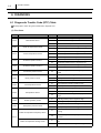
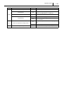
7.2 Engine ECU Connector Diagram
Engine ECU Connector Pin Layout
Terminal Connections (A-side, pins 1-48)
No.
1
3
Pin Symbol
COMMON2
TWV4
Connections
No.
Injector common 2
Injector #2
Pin Symbol
Connections
25
COMMON2
Injector common 2
26
TWV2
Injector #3
27
28
5
SCV-
Suction control valve (SCV) (-)
29
SCV+
Suction control valve (SCV) (+)
6
THF-GND
Fuel temperature sensor (GND)
30
THF
Fuel temperature sensor (Signal)
7
THW-GND
Coolant temperature sensor (GND)
31
THW
Coolant temperature sensor (Signal)
8
LVNT-GND
32
LVNT
9
LVSS-GND
33
LVSS
10
LEGR-GND
EGR position sensor (GND)
34
LEGR
EGR position sensor (Signal)
11
PIM-GND
Boost pressure sensor (GND)
35
PIM
Boost pressure sensor (Signal)
12
PFUEL-GND
Rail pressure sensor (GND)
36
PFUEL
Rail pressure sensor (Signal)
13
PFUEL-SLD
Rail pressure sensor (Shield)
37
PFUEL
Rail pressure sensor (Signal)
14
MAF-GND
Mass airflow sensor (GND)
38
IAT
15
PExhD-GND
Differential pressure sensor (GND)
39
PExhD
16
THExh1-GND
40
THExh1
17
THExh2-GND
41
THExh2
18
THExh3-GND
42
THExh3
19
G-SLD
Cylinder recognition sensor (Shield)
43
G+
Cylinder recognition sensor (+)
20
NE-SLD
Crankshaft position sensor (Shield)
44
G-
Cylinder recognition sensor (-)
21
VNT-
Variable nozzle turbo DC motor (-)
45
NE+
Crankshaft position sensor (+)
22
VNT+
Variable nozzle turbo DC motor (+)
46
NE-
Crankshaft position sensor (-)
Variable nozzle turbo position sensor (GND)
Variable swirl control position sensor
(GND)
Exhaust
temperature
sensor
1
(GND)
Exhaust
temperature
sensor
2
(GND)
Exhaust
temperature
sensor
3
(GND)
23
47
24
48
Variable nozzle turbo position sensor (Signal)
Variable swirl control position sensor
(Signal)
Intake air temperature sensor 2
(Signal)
Differential pressure sensor (Signal)
Exhaust temperature sensor 1 (Signal)
Exhaust temperature sensor 2 (Signal)
Exhaust temperature sensor 3 (Signal)
Operation Section
1 24
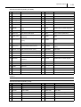
Terminal Connections (A-side, pins 49-96)
No.
49
Pin Symbol
COMMON1
Connections
Injector common 1
50
51
TWV3
Injector #4
No.
Pin Symbol
Connections
73
COMMON1
Injector common 1
74
TWV1
Injector #1
79
I/T-DI
Diesel throttle controller diagnosis
75
52
76
53
77
54
SPAD-VCC
Spare
78
55
VNT-DI
56
LOIL-SW
OIL level SW signal
80
ACG-F
ACG F-terminal (Alternator)*1
57
POIL-SW
OIL pressure SW signal
81
ACG-L
ACG L-terminal (Alternator)*1
58
LVNT-VCC2
82
S-SW1
Spare
59
LVSS-VCC2
83
S-SW2
Spare
60
LEGR-VCC2
EGR position sensor (VCC)
84
S-SW3
Spare
61
PIM-VCC2
Boost pressure sensor (VCC)
85
IAT-ANG
62
PFUEL-VCC2
Rail pressure sensor (VCC)
86
EGR-GND
EGR shield
63
PExhD-VCC2
Differential pressure sensor (VCC)
87
BY-PASS
EGR By-pass Valve
64
G-VCC2
Cylinder recognition sensor (VCC)
88
S-REL2
Spare
65
E-VCC1
Crankshaft position sensor (VCC)
89
S-LMP1
Spare
66
IAT-FRQ
90
INT-CS
Diesel throttle controller (Signal)
67
MAF-FRQ
Mass airflow sensor frequency
91
VNT
Turbo solenoid
68
CAN-H
CAN High
92
VSS
Variable swirl control solenoid
69
CAN-L
CAN Low
93
Variable nozzle turbo actuator diagnosis
Variable nozzle turbo position sensor (VCC)
Variable swirl control position sensor
(VCC)
Mass airflow sensor air temperature
frequency
70
Mass airflow sensor air temperature
Analog
94
71
SP-FRQ
Spare
95
SP-FRQ1
Spare
72
EGR-
EGR DC motor (-)
96
EGR+
EGR DC motor (+)
< NOTE >
*1 : Meriva only
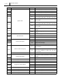
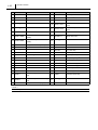
Terminal Connections (B-side, pin 58)
No.
Pin Symbol
Connections
No.
1
GND
Signal, sensor GND
30
2
GND
Signal, sensor GND
31
3
P-GND
Power GND
4
P-GND
5
6
Pin Symbol
Connections
LFUEL
Fuel level signal
32
CASE-GND
Case GND
Power GND
33
GL-DI
Glow controller diagnosis
+B
Power +B
34
RG-SW
Reverse gear switch
+B
Power +B
35
LW-SW
Water level switch
36
FAN1
Fan 1
Operation Section
1 25
No.
Pin Symbol
Connections
No.
Pin Symbol
Connections
8
STT-SW
Starter switch*1
37
SPD
Vehicle speed sensor*1
9
IG-SW
Ignition 1
38
KWP2000
ISO 14230*1
10
IG-SW
Ignition 0
39
Accelerator
position
sensor
1
position
sensor
2
11
40
ACCP1-VCC1
12
41
ACCP2-VCC2
13
42
PAC-VCC2
A/C pressure sensor (VCC)
43
STT-REL-H
Starter relay HSD
Accelerator
position
sensor
1
position
sensor
2
14
ACCP1-GND
15
ACCP2-GND
16
PAC-GND
A/C pressure sensor (GND)
45
17
LFUEL-GND
Fuel level return
46
(GND)
Accelerator
(GND)
(VCC)
Accelerator
(VCC)
44
18
47
ACT-REL
A/C cutoff relay
19
48
FAN3-REL
Fan 3 relay
20
GMLAN-H
GMLAN High
49
NEOUT
Engine speed output *1
21
GMLAN-L
GMLAN Low
50
FUELOUT
Fuel quantity output*1
51
MIL
Check engine warning light*1
22
23
CL-SW
Clutch switch
52
FH-REL
Fuel heater relay
24
BK2-SW
Brake 2 switch
53
GL-CS
Glow controller signal
25
BK1-SW
Brake 1 switch
54
FAN2-REL
Fan 2 relay
26
EH-SW
Electrical heater switch
55
STT-REL-L
Starter relay LSD
27
ACCP1
56
M-REL
Powertrain main relay
28
ACCP2
29
PAC
< NOTE >
*1 : Meriva only
Accelerator position sensor 1 (Signal)
Accelerator position sensor 2 (Signal)
A/C pressure sensor (Signal)
57
58
Published
: January 2007
Edited and published by:
DENSO CORPORATION
Service Department
1-1 Showa-cho, Kariya, Aichi Prefecture, Japan