1
Diesel Injection Pump
SERVICE MANUAL
COMMON RAIL SYSTEM (CRS)
FOR ISUZU 6DE1 ENGINE
OPERATION
April, 2006
00400558E
© 2006 DENSO CORPORATION
All Rights Reserved. This book may not be reproduced
or copied, in whole or in part, without the written
permission of the publisher.
Table of Contents
Table of Contents
Operation Section
1. PRODUCT APPLICATION INFORMATION
1.1
Outline . . . . . . . . . . . . . . . . . . . . . . . . . . . . . . . . . . . . . . . . . . . . . . . . . . . . . . . . . . . . . . . . . . . . . . . . . . . . . . . . 1-1
1.2
Application . . . . . . . . . . . . . . . . . . . . . . . . . . . . . . . . . . . . . . . . . . . . . . . . . . . . . . . . . . . . . . . . . . . . . . . . . . . . . 1-1
1.3
System Component Part Numbers . . . . . . . . . . . . . . . . . . . . . . . . . . . . . . . . . . . . . . . . . . . . . . . . . . . . . . . . . . 1-1
2. RAIL
2.1
Outline . . . . . . . . . . . . . . . . . . . . . . . . . . . . . . . . . . . . . . . . . . . . . . . . . . . . . . . . . . . . . . . . . . . . . . . . . . . . . . . . 1-3
2.2
Rail Pressure (Pc) Sensor . . . . . . . . . . . . . . . . . . . . . . . . . . . . . . . . . . . . . . . . . . . . . . . . . . . . . . . . . . . . . . . . . 1-3
2.3
Pressure Limiter . . . . . . . . . . . . . . . . . . . . . . . . . . . . . . . . . . . . . . . . . . . . . . . . . . . . . . . . . . . . . . . . . . . . . . . . 1-4
3. INJECTORS
3.1
Outline . . . . . . . . . . . . . . . . . . . . . . . . . . . . . . . . . . . . . . . . . . . . . . . . . . . . . . . . . . . . . . . . . . . . . . . . . . . . . . . . 1-5
3.2
QR Code . . . . . . . . . . . . . . . . . . . . . . . . . . . . . . . . . . . . . . . . . . . . . . . . . . . . . . . . . . . . . . . . . . . . . . . . . . . . . . 1-6
3.3
Handling Injectors with QR Codes (Reference). . . . . . . . . . . . . . . . . . . . . . . . . . . . . . . . . . . . . . . . . . . . . . . . . 1-6
4. ELECTRONIC DRIVING UNIT (EDU)
4.1
Outline . . . . . . . . . . . . . . . . . . . . . . . . . . . . . . . . . . . . . . . . . . . . . . . . . . . . . . . . . . . . . . . . . . . . . . . . . . . . . . . . 1-7
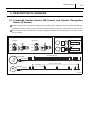
5. DESCRIPTION OF SENSORS
5.1
Crankshaft Position Sensor (NE Sensor) and Cylinder Recognition Sensor (G Sensor) . . . . . . . . . . . . . . . . . 1-8
6. CONTROL SYSTEMS
6.1
Control System . . . . . . . . . . . . . . . . . . . . . . . . . . . . . . . . . . . . . . . . . . . . . . . . . . . . . . . . . . . . . . . . . . . . . . . . . 1-9
6.2
Actuator System . . . . . . . . . . . . . . . . . . . . . . . . . . . . . . . . . . . . . . . . . . . . . . . . . . . . . . . . . . . . . . . . . . . . . . . . 1-9
6.3
Sensor System . . . . . . . . . . . . . . . . . . . . . . . . . . . . . . . . . . . . . . . . . . . . . . . . . . . . . . . . . . . . . . . . . . . . . . . . 1-10
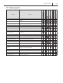
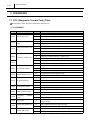
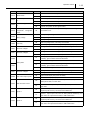
7. DIAGNOSIS
7.1
DTC (Diagnostic Trouble Code) Table. . . . . . . . . . . . . . . . . . . . . . . . . . . . . . . . . . . . . . . . . . . . . . . . . . . . . . . 1-11
8. EXTERNAL WIRING DIAGRAM
8.1
ECU External Wiring Diagram . . . . . . . . . . . . . . . . . . . . . . . . . . . . . . . . . . . . . . . . . . . . . . . . . . . . . . . . . . . . . 1-23
8.2
ECU Connector Diagram. . . . . . . . . . . . . . . . . . . . . . . . . . . . . . . . . . . . . . . . . . . . . . . . . . . . . . . . . . . . . . . . . 1-27
Operation Section
1 1
1. PRODUCT APPLICATION INFORMATION
1.1 Outline
The Common Rail System (CRS) used for the ISUZU 6DE1 engine in the RENAULT/OPEL has been redesigned to
comply with EURO 4 emission regulations. The details of the CRS described herein are basically the same as those in
the service bulletin entitled, "S/B Code: ECD 02-07, Subject: Common Rail System (ECD-U2P) for ISUZU Engine", issued in May, 2003. The two major points that have changed for this system are the addition of a Diesel Particulate Filter
(DPF) system, and injectors equipped with the QR codes. This service bulletin describes change items only. Use this
bulletin in conjunction with the S/B Code: ECD 02-07 service bulletin mentioned above.
1.2 Application
Manufacturer Name
RENAULT
Model Name
Destination
Vel Satis
Espace
Release for Sale
November, 2005
6DE1
Signum
OPEL
Engine
Europe
Vectra
1.3 System Component Part Numbers
For RENAULT
Parts Name
DENSO Parts Number
Manufacturer Parts Number
Cylinder recognition sensor
949979-156#
897353105#
Crankshaft position sensor
949979-120#
'897321620#
Rail
095440-072#
897353063#
EDU
131000-146#
897353189#
275800-387#
897353186#
Vel Satis
275800-389#
897353501#
Espace
275800-388#
897353502#
Espace
Injector
095000-583#
897353080#
Supply pump
097300-002#
897228919#
Engine ECU
Remarks
HP2 type
Operation Section
For OPEL
Parts Name
DENSO Parts Number
Manufacturer Parts Number
Cylinder recognition sensor
949979-156#
897353105#
Crankshaft position sensor
949979-120#
'897321620#
Rail
095440-072#
897353063#
EDU
131000-145#
897353040#
275800-391#
897353188#
MT
275800-392#
'897379557#
AT
275800-393#
898009250#
Spare parts
Injector
095000-583#
897353080#
Supply pump
097300-002#
897228919#
Engine ECU
Remarks
HP2 type
1 2
1 3
Operation Section
2. RAIL
2.1 Outline
The overall shape of the rail has been changed. In addition, the rail pressure sensor and pressure limiter have been
modified.
2.2 Rail Pressure (Pc) Sensor
The shape of the rail pressure sensor terminals and sensor output characteristics have been changed.
Operation Section
2.3 Pressure Limiter
The pressure limiter closing pressure has been changed from 171MPa to 181MPa.
1 4
1 5
Operation Section
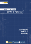
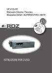
3. INJECTORS
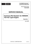
3.1 Outline
The X2 type injectors used previously have been changed to the G2 type, and now employ QR codes. Injector operation
has not changed. For details on operation, refer to the service bulletin entitled, "S/B Code: ECD 02-07, Subject: Common Rail System (ECD-U2P) for ISUZU Engine", starting on page 16.
Construction
Operation Section
1 6
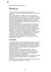
3.2 QR Code
QR (Quick Response) codes have been adopted to enhance the injection quantity precision of the injectors. The adoption of QR codes minimizes injection quantity deviation control throughout all pressure ranges, improving combustion
efficiency, reducing emissions, etc.
3.3 Handling Injectors with QR Codes (Reference)
Injectors with QR codes have the engine ECU recognize and correct the injectors, so when an injector or the engine
ECU is replaced, it is necessary to register the injector's ID code in the engine ECU.
(1) Replacing the Injector
It is necessary to register the ID code of the injector that has been replaced in the engine ECU.
(2) Replacing the Engine ECU
It is necessary to register the ID codes of all the vehicle injectors in the replaced engine ECU.
1 7
Operation Section
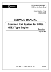
4. ELECTRONIC DRIVING UNIT (EDU)
4.1 Outline
The injector actuation circuit has been changed to include two systems. The EDU in the RENAULT actuation circuit has
been changed to include two outputs, while the OPEL actuation circuit has been changed to include two EDUs.In accordance with these changes, there are now two injection verification signals. Actuation for Injectors 1,3, and 5 is via
COM1, with the corresponding verification signal transmitted via IJF1. Actuation for injectors 2,4, and 6 is via COM2,
with the corresponding verification signal transmitted via IJF2. All remaining terminals have not been changed. For details on terminals other than those mentioned above, refer to the service bulletin entitled, "S/B Code: ECD 02-07, Subject: Common Rail System (ECD-U2P) for ISUZU Engine", starting on page 16.
Operation Section
1 8
5. DESCRIPTION OF SENSORS
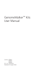
5.1 Crankshaft Position Sensor (NE Sensor) and Cylinder Recognition
Sensor (G Sensor)
The NE sensor has been changed from a Magnetic Pickup (MPU) type to a Magnetic Resistance Element (MRE) type.
In addition the number of pulse-gear teeth has been changed to equal 56 pulses (four missing teeth) for every 360 °CA.
The crank position sensor has also been changed to a Magnetic Resistance Element (MRE) type. The number of teeth
has not changed.
1 9
Operation Section
6. CONTROL SYSTEMS
6.1 Control System
6.2 Actuator System
Operation Section
6.3 Sensor System
1 10
Operation Section
1 11
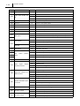
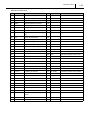
7. DIAGNOSIS
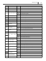
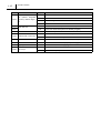
7.1 DTC (Diagnostic Trouble Code) Table
Read symptom codes using the manufacturer's diagnostic tool.
(1) For RENAULT
DTC
P0100
P0110
P0115
Failure Part
Mass air flow sensor
Intake
air
temperature
sensor
Coolant temperature sensor
P0225
Accelerator position sensor
P2120
P0235
P0180
P0190
Turbo pressure sensor
Fuel temperature sensor
Rail pressure sensor
P0195
Oil temperature sensor
P0409
EGR lift (position) sensor
P2226
P2146
P0070
Symptom
Failure Mode
03
Mass air flow sensor signal too high
14
Mass air flow sensor signal too low
06
Mass air flow sensor performance invalid
15
Intake air temperature sensor signal too high
02
Intake air temperature sensor signal too low
15
Coolant temperature sensor signal too high
02
Coolant temperature sensor signal too low
06
Coolant temperature sensor performance invalid
03
Accelerator position sensor No.1 signal too high
14
Accelerator position sensor No.1 signal too low
06
Accelerator position sensor signal performance invalid
03
Accelerator position sensor No.2 signal too high
14
Accelerator position sensor No.2 signal too low
03
Turbo pressure sensor signal too high
14
Turbo pressure sensor signal too low
06
Turbo pressure sensor performance invalid
15
Fuel temperature sensor signal too high
02
Fuel temperature sensor signal too low
15
Rail pressure sensor signal too high
02
Rail pressure sensor signal too low
0C
Rail pressure sensor signal stuck in the middle range
15
Oil temperature sensor signal too high
02
Oil temperature sensor signal too low
03
EGR lift (position) sensor signal too high
14
EGR lift (position) sensor signal too low
03
Atmospheric pressure sensor signal too high
sensor
14
Atmospheric pressure sensor signal too low
Injector/EDU
06
Ambient temperature sen-
15
Ambient temperature sensor signal too high
sor
02
Ambient temperature sensor signal too low
00
Intake throttle lift (position) sensor signal too high
00
Intake throttle lift (position) sensor signal too low
Atmospheric
pressure
Intake throttle sensor
Injector fail pattern is not confirmed. (Multi injection is NG, single
injection is OK.)
Operation Section
DTC
P0512
P0335
P0340
Failure Part
Symptom
Starter switch short to battery
14
Starter switch open/short to GND
Crankshaft position sen-
07
Crankshaft position sensor no pulse
sor
06
Crankshaft position sensor signal invalid
Cylinder recognition sen-
07
Cylinder recognition sensor no pulse
sor
06
Cylinder recognition sensor signal invalid
Crankshaft position senP0016
Failure Mode
03
Starter switch
sor/Cylinder
recognition
1 12
Crankshaft position sensor/cylinder recognition sensor signal syn06
chronization error
09
Battery voltage too high
08
Battery voltage too low
00
Battery voltage unstable malfunction
0B
Main relay diagnostics; main relay stuck closed
0A
Main relay diagnostics; main relay stuck open/relay output open load
09
Analog sensor reference voltage output No.1 too high
08
Analog sensor reference voltage output No.1 too low
09
Analog sensor reference voltage output No.2 too high
08
Analog sensor reference voltage output No.2 too low
sensor
P0560
Battery voltage
P0685
Main relay
P0641
Reference voltage1
P0651
Reference voltage2
15
P0380
Glow system
02
15
P0382
P0697
Reference voltage3
P0660
Swirl control output (VSV)
Glow plug R side open load short, glow diagnosis line open load/short
to battery, glow controller internal malfunction
09
Analog sensor reference voltage output No.3 too high
08
Analog sensor reference voltage output No.3 too low
03
Swirl control output (VSV) short to battery
14
Swirl control output (VSV) open load/short to GND
EGR control DC motor
03
Injector 1
14
03
P0202
Glow controller diagnosis line 1 short to GND
Glow controller diagnosis line 2 short to GND
01
P0201
to battery, glow controller internal malfunction
02
0C
P0403
Glow plug R side open load short, glow diagnosis line open load/short
Injector 2
14
EGR DC motor output 1 short to battery/short GND, output 2 short to
battery/short GND, or motor short
EGR DC motor output 1 open load, output 2 open load/, or motor
open load
Injector 1 output short to GND (with resistance), short to battery
(injection pulse<0.7ms), coil short; EDU malfunction
Injector 1 output open load, short to GND (without resistance), coil
open load; IJT1 open/short to GND, or EDU malfunction
Injector 2 output short to GND (with resistance), short to battery
(injection pulse<0.7ms), coil short; EDU malfunction
Injector 2 output open load, short to GND (without resistance), coil
open load; IJT2 open/short to GND, or EDU malfunction
Operation Section
1 13
DTC
Failure Part
Symptom
03
P0203
Injector 3
14
03
P0204
Injector 4
14
03
P0205
Injector 5
14
03
P0206
Injector 6
14
Failure Mode
Injector 3 output short to GND (with resistance), short to battery
(injection pulse<0.7ms), coil short; EDU malfunction
Injector 3 output open load, short to GND (without resistance), coil
open load; IJT3 open/short to GND, or EDU malfunction
Injector 4 output short to GND (with resistance), short to battery
(injection pulse<0.7ms), coil short; EDU malfunction
Injector 4 output open load, short to GND (without resistance), coil
open load; IJT4 open/short to GND, or EDU malfunction
Injector 5 output short to GND (with resistance), short to battery
(injection pulse<0.7ms), coil short; EDU malfunction
Injector 5 output open load, short to GND (without resistance), coil
open load; IJT5 open/short to GND, or EDU malfunction
Injector 6 output short to GND (with resistance), short to battery
(injection pulse<0.7ms), coil short; EDU malfunction
Injector 6 output open load, short to GND (without resistance), coil
open load; IJT6 open/short to GND, or EDU malfunction
Injector 1, 3, or 5 output short to battery (when injection
pulse>0.7ms)/short to GND (failure occurred when EDU power was
0C
OFF); IJT1, 3, or 5 output short to battery; IJF1 output short to GND;
COM1 open load/short to GND (failure occurred when EDU power
was OFF), COM1 short to battery, or EDU malfunction
P062D Injector drive1
Injector 1, 3, or 5 output short to GND (failure occurred when EDU
06
power was ON); IJF1 output short to battery/open load; COM1 open
load/short to GND (failure occurred when EDU power was ON), EDU
malfunction
Injector 2, 4, or 6 output short to battery (when injection
pulse>0.7ms)/short to GND (failure occurred when EDU power was
0C
OFF); IJT2, 4, or 6 output short to battery; IJF2 output short to GND;
COM2 open load/short to GND (failure occurred when EDU power
P062E
was OFF), COM2 short to battery, or EDU malfunction
Injector drive2
Injector 2, 4, or 6 output short to GND (failure occurred when EDU
06
power was ON); IJF2 output short to battery/open load; COM2 open
load/short to GND (failure occurred when EDU power was ON), EDU
malfunction
P2146
P0611
P0230
P0190
EDU battery open load/short to GND, EDU GND open load/short to
EDU
12
Injector/EDU
0D
Unknown failure pattern, EDU malfunction
16
QR code not programmed
0D
QR code ERROR
06
QR correction information is abnormal
03
SCV COM short to battery; SCV1, 2 output short to battery
QR code
Pump SCV
Rail system
06
battery, EDU malfunction
SCV COM short to GND/open load; SCV1, 2 (COM side) short to
GND; unknown SCV failure
14
SCV1, 2 output open load/short to GND; SCV1, 2 coil open
0C
SCV1, 2 coil short
06
Rail pressure sensor performance invalid included fuel leak
Operation Section
DTC
Failure Part
Symptom
Failure Mode
P0088
Rail pressure sensor
09
Rail pressure exceeds upper limit
P0093
Rail pressure limiter
05
Pressure limiter activated
P0217
Engine overheat
09
Engine overheat
P0219
Engine overrun
09
Engine overrun
16
Check sum error-flash area
0D
CPU fault; main CPU fault
06
CPU fault; watchdog IC fault
P0606
Engine ECU internal failure
P0301
Injector 1
13
Cylinder 1 fuel system failure
P0302
Injector 2
13
Cylinder 2 fuel system failure
P0303
Injector 3
13
Cylinder 3 fuel system failure
P0304
Injector 4
13
Cylinder 4 fuel system failure
P0305
Injector 5
13
Cylinder 5 fuel system failure
P0306
Injector 6
13
Cylinder 6 fuel system failure
09
EGR excessive flow (EGR positive deviation)
08
EGR insufficient flow (EGR negative deviation)
04
EGR valve close stuck
08
Turbo control system (negative deviation)
09
Turbo control system (positive deviation)
07
CAN2 turbo unit absent
0E
Turbo unit failure
05
EGR valve open stuck
08
Swirl control flap remains closed
09
Swirl control flap remains open
08
Swirl control flap remains closed
09
Swirl control flap remains open
0B
EGR DC motor lock
03
Fan control relay 1 short to battery
14
Fan control relay 1 open load/short to GND
03
Fan control relay 2 short to battery
14
Fan control relay 2 open load/short to GND
Thermo plunger relay 1
03
Thermo plunger relay 1 short to battery
output
14
Thermo plunger relay 1 open load/short to GND
Thermo plunger relay 2
03
Thermo plunger relay 2 short to battery
output
14
Thermo plunger relay 2 open load/short to GND
Thermo plunger relay 3
03
Thermo plunger relay 3 short to battery
output
14
Thermo plunger relay 3 open load/short to GND
00
Intake throttle close stuck
00
Intake throttle open stuck
0A
Variable nozzle turbo valve stuck closed
0B
Variable nozzle turbo valve stuck open
16
Turbo unit failure2
P0402
P0401
EGR system
P0401
EGR valve
P2263
Turbo system
P0243
Turbo unit
P0402
EGR valve
P0660
Swirl
control
position
switch
P0663
P0403
EGR DC motor
P0480
Fan relay 1 output
P0481
Fan relay 2 output
P1641
P1642
P1643
Intake throttle
P0235
Variable nozzle turbo
P0243
Turbo unit
1 14
Operation Section
1 15
DTC
Failure Part
VIF
P0575
(Vehicle
Integrated
Function) related diagnosis
U0101
U0121
CAN data error
EGR
Symptom
Failure Mode
80
One of the two brake contacts
81
Both brake contacts
82
Cruise analog switch malfunction
83
Cruise main switch malfunction
0E
CAN frame absent AGB (Automatic Gear Box)
0E
CAN frame absent ESP (Electronic Stability Program)
00
EGR over temperature
03
Intake shutter control VSV short to battery
14
Intake shutter control VSV open load/short to GND
P2100
Intake throttle control VSV
P0409
EGR valve
06
EGR lift sensor characteristic abnormality (learning value fault)
P0100
Mass air flow sensor
0A
Mass air flow sensor too low (keep output voltage)
P2263
Popping-off
0A
Variable nozzle turbo hose popping off
P0482
Fan relay 3
03
Fan control relay 3 short to battery
14
Fan control relay 3 open load/short to GND
Operation Section
1 16
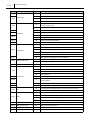
(2) For OPEL
DTC
P0100
P0110
P0115
P1120
Failure Part
Mass air flow sensor signal too high
03
Mass air flow sensor signal too low
52
Mass air flow sensor performance invalid
07
Intake air temperature sensor signal too high
03
Intake air temperature sensor signal too low
07
Coolant temperature sensor signal too high
03
Coolant temperature sensor signal too low
52
Coolant temperature sensor performance invalid
Accelerator position sen-
07
Accelerator position sensor No.1 signal too high
sor 1
03
Accelerator position sensor No.1 signal too low
52
Accelerator position sensor signal performance invalid
Accelerator position sen-
07
Accelerator position sensor No.2 signal too high
sor 2
03
Accelerator position sensor No.2 signal too low
07
Turbo pressure sensor signal too high
03
Turbo pressure sensor signal too low
52
Turbo pressure sensor performance invalid
07
Fuel temperature sensor signal too high
03
Fuel temperature sensor signal too low
07
Rail pressure sensor signal too high
03
Rail pressure sensor signal too low
52
Rail pressure sensor signal stuck in the middle range
07
Oil temperature sensor signal too high
03
Oil temperature sensor signal too low
07
EGR lift (position) sensor signal too high
03
EGR lift (position) sensor signal too low
07
Atmospheric pressure sensor signal too high
sensor
03
Atmospheric pressure sensor signal too low
Injector 1-6
50
Ambient temperature sen-
07
Ambient temperature sensor signal too high
sor
03
Ambient temperature sensor signal too low
07
Intake throttle lift (position) sensor signal too high
03
Intake throttle lift (position) sensor signal too low
Crankshaft position sen-
29
Crankshaft position sensor no pulse
sor
2C
Crankshaft position sensor signal invalid
Cylinder recognition sen-
29
Cylinder recognition sensor no pulse
sor
2C
Cylinder recognition sensor signal invalid
Mass air flow sensor
Intake
air
temperature
sensor
Coolant temperature sensor
sor performance
P0105
P0180
P0190
Turbo pressure sensor
Fuel temperature sensor
Rail pressure sensor
P0195
Oil temperature sensor
P0409
EGR lift (position) sensor
P1105
P1216
P1070
P0638
P0335
P0340
P0016
Failure Mode
07
Accelerator position sen-
P1122
Symptom
Atmospheric
pressure
Intake throttle sensor
Crankshaft position/cylinder recognition
2B
Injector fail pattern is not confirmed. (multi injection is NG, single
injection is OK.)
Crankshaft position sensor/cylinder recognition sensor signal synchronization error
Operation Section
1 17
DTC
P0560
Failure Part
Battery voltage
P1625
Main relay
P1620
Reference voltage1
P1635
Reference voltage2
Symptom
07
Battery voltage too high
03
Battery voltage too low
52
Battery voltage unstable malfunction
63
Main relay diagnostics; main relay stuck closed
0A
Main relay diagnostics; main relay stuck open/relay output open load
07
Analog sensor reference voltage output No. 1 too high
03
Analog sensor reference voltage output No. 1 too low
07
Analog sensor reference voltage output No. 2 too high
03
Analog sensor reference voltage output No. 2 too low
05
P0380
Glow system
02
05
P0382
02
01
P0381
Glow controller
06
P1639
Reference voltage3
P1625
Main relay
P1243
Swirl control output (VSV)
P0403
EGR control DC motor
P0638
Intake throttle control DC
motor
Glow controller diagnosis line 1 short to GND
Glow plug L side open load/short, glow diagnosis line 2 open load/
short to battery, glow controller internal malfunction
Glow controller diagnosis line 2 short to GND
Glow controller command line short to battery; glow controller internal
malfunction
Glow controller command line open load/short to GND; glow controller internal malfunction
03
Analog sensor reference voltage output No.3 too low
01
Main relay/relay output short to battery
02
Main relay/relay output short to GND
01
Swirl control output (VSV) short to battery
06
Swirl control output (VSV) open load/short to GND
10
EGR DC motor output 1, 2 short to battery/short to GND; motor short
04
EGR DC motor output 1, 2 open load; motor open load
10
04
Injector 1
01
Injector 2
04
01
P1293
short to battery, glow controller internal malfunction
Analog sensor reference voltage output No.3 too high
04
P1292
Glow plug R side open load/short, glow diagnosis line 1 open load/
07
01
P1291
Failure Mode
Injector 3
04
Intake throttle DC motor output 1, 2 short to battery/short to GND;
motor short
Intake throttle DC motor output 1, 2 open load; motor open load
Injector 1 output short to GND (with resistance), short to battery
(injection pulse<0.7ms), coil short; EDU malfunction
Injector 1 output open load, short to GND (without resistance), open
load; IJT1 open/short to GND, EDU malfunction
Injector 2 output short to GND (with resistance), short to battery
(injection pulse<0.7ms), coil short; EDU malfunction
Injector 2 output open load, short to GND (without resistance), coil
open load; IJT2 open/short to GND, EDU malfunction
Injector 3 output short to GND (with resistance), short to battery
(injection pulse<0.7ms), coil short; EDU malfunction
Injector 3 output open load, short to GND (without resistance), coil
open load; IJT3 open/short to GND, EDU malfunction
Operation Section
DTC
Failure Part
Symptom
01
P1294
Injector 4
04
01
P1295
Injector 5
04
01
P1296
Injector 6
04
1 18
Failure Mode
Injector 4 output short to GND (with resistance), short to battery
(injection pulse<0.7ms), coil short; EDU malfunction
Injector 4 output open load, short to GND (without resistance), coil
open load; IJT4 open/short to GND, EDU malfunction
Injector 5 output short to GND (with resistance), short to battery
(injection pulse<0.7ms), coil short; EDU malfunction
Injector 5 output open load, short to GND (without resistance), coil
open load; IJT5 open/short to GND, EDU malfunction
Injector 6 output short to GND (with resistance), short to battery
(injection pulse<0.7ms), coil short; EDU malfunction
Injector 6 output open load, short to GND (without resistance), coil
open load; IJT6 open/short to GND, EDU malfunction
Injector 1 or 3 or 5 output short to battery (injection pulse>0.7ms),
injector 1 or 3 or 5 output short to GND (failure occurred when EDU
P0200
Injector drive1
00
power off), IJT1 or 3 or 5 output short to battery, IJF1 output short to
GND, COM1 open load/short to GND (failure occurred when EDU
power off), COM1 short to battery, EDU malfunction
Injector 2 or 4 or 6 output short to battery (injection pulse>0.7ms),
injector 2 or 4 or 6 output short to GND (failure occurred when EDU
P1200
Injector drive2
00
power off), IJT2 or 4 or 6 output short to battery, IJF2 output short to
GND, COM2 open load/short to GND (failure occurred when EDU
power off), COM2 short to battery, EDU malfunction
IJF1 output open load/short to battery, injector 1 or 3 or 5 output short
Injector drive1
1A
to GND (failure occurred when EDU power on), COM1 open load/
short to GND (failure occurred when EDU power on), EDU malfunction
IJF2 output open load/short to battery, injector 2 or 4 or 6 output short
P1216
Injector drive2
1B
to GND (failure occurred when EDU power on), COM2 open load/
short to GND (failure occurred when EDU power on), EDU malfunction
P0602
P0251
EDU battery open load/short to GND, EDU GND open load/short to
EDU
00
Injector/EDU
08
Unknown failure pattern. EDU malfunction
52
QR code not programmed
51
QR code error
53
QR correction information abnormal
01
SCV COM short to battery; SCV1, 2 output short to battery
QR code
Pump SCV
06
battery, EDU malfunction
SCV COM short to GND/open load; SCV1, 2 (COM side) short to
GND; unknown SCV failure
04
SCV1, 2 output open load/short to GND; SCV1, 2 coil open
0E
SCV1, 2 coil short
P0093
Common rail system
00
Rail pressure sensor performance invalid included fuel leak
P0190
Rail pressure sensor
11
Rail pressure exceeds upper limit
P1190
Rail pressure limiter
00
Pressure limiter activated
P0217
Engine overheat
00
Engine overheat
Operation Section
1 19
DTC
P0219
P0606
Failure Part
Engine overrun
Engine ECU internal failure
Symptom
Failure Mode
00
Engine overrun
35
Check sum error-flash area
30
CPU fault; main CPU fault
37
CPU fault; watchdog IC fault
P0301
Injector 1
00
Cylinder 1 fuel system failure
P0302
Injector 2
00
Cylinder 2 fuel system failure
P0303
Injector 3
00
Cylinder 3 fuel system failure
P0304
Injector 4
00
Cylinder 4 fuel system failure
P0305
Injector 5
00
Cylinder 5 fuel system failure
P0306
Injector 6
00
Cylinder 6 fuel system failure
11
EGR excessive/insufficient flow (EGR positive deviation)
12
EGR excessive/insufficient flow (EGR negative deviation)
63
EGR valve close stuck
12
Turbo control system (negative deviation)
11
Turbo control system (positive deviation)
70
CAN2 turbo unit absent
00
Turbo unit failure
62
EGR valve open stuck
63
Swirl control flap remains closed
62
Swirl control flap remains open
63
Swirl control flap remains closed
62
Swirl control flap remains open
61
EGR DC motor lock
07
Voltage too high
03
Voltage too low
54
Temperature too high
53
Temperature too low
07
Voltage too high
Upper DPF catalyst tem-
03
Voltage too low
perature sensor
54
Temperature too high
53
Temperature too low
07
Voltage too high
Exhaust deferential pres-
03
Voltage too low
sure sensor
11
difference pressure too high
12
Hose line disconnected upstream
52
Rail pressure deviation too big
01
Fan control relay 1 short to battery
06
Fan control relay 1 open load/short to GND
01
Fan control relay 2 short to battery
06
Fan control relay 2 open load/short to GND
P0400
EGR system
P0409
Turbo system
P0235
Turbo unit
P0409
EGR system
P1109
P1110
Swirl
P1111
switch
control
position
P1112
P0403
P0425
P1902
P1901
EGR DC motor
Upper
oxygen
catalyst
temperature sensor
P0093
Rail pressure
P1481
Fan relay 1 output
P1482
Fan relay 2 output
Operation Section
DTC
Failure Part
P1483
Fan relay 3 output
P1530
A/C relay
P0615
Starter relay
P0501
Vehicle speed
Symptom
1 20
Failure Mode
01
Fan control relay 3 short to battery
06
Fan control relay 3 open load/short to GND
01
A/C relay output short to battery
06
A/C relay output open load/short to GND
01
Starter relay output short to battery
06
Starter relay output open load/short to GND
07
Vehicle speed too high
03
Vehicle speed too low
08
Vehicle speed too invalid
07
A/C pressure sensor signal too high
03
A/C pressure sensor signal too low
07
Fuel level sensor signal too high
03
Fuel level sensor signal too low
P0530
A/C pressure
P0460
Fuel level sensor
P0571
Brake switch
08
P0704
Clutch switch
00
Clutch switch malfunction
P0520
Oil pressure switch
63
Oil pressure switch stuck closed
62
Oil pressure switch stuck open
01
Check engine warning light short to battery
06
Check engine warning light open load/short to GND
07
Alternator L-terminal short to battery/open
03
Alternator L-terminal short to GND, Generator failure
U2103
70
Node error (Bus-off)
U2106
70
Transmission general status frame receive is failed
70
Antilock brakes general status frame receive is failed
U2139
70
CIM (Column Integrated Module) general frame receive is failed
U2144
70
ACC (Adaptive Cruise Control) general status frame receive is failed
P0700
00
Transmission emission related malfunction
P1700
00
Service transmission system
P1035
71
Wheel speed signal set to invalid
71
Wheel rotation signal set to invalid
71
TCM (Transmission Control Module) actual gear set to invalid
72
TCM request torque RC (Rolling Counter) error
71
Outside air temperature invalid
72
TRC (Traction Control System) request torque RC error
74
TRC request torque protection value error
4D
Vmax (Maximum Vehicle Speed) limitation speed is not programmed
54
Fuel quantity reduction by exhaust temperature
P0650
P0621
U2108
Check
engine
warning
light
Alternator L-terminal
CAN data error
P0500
P0705
P1813
VIF
(Vehicle
Integrated
Function) related diagnosis
P0070
P1811
P1602
P0217
Engine overheat
Brake switch inactive error when vehicle deceleration (two brake
error)
Operation Section
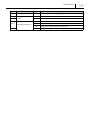
1 21
DTC
Failure Part
P1814
P1565
Cruise switch
Symptom
71
ECC (Electronic Climate Control) torque set to invalid
71
Cruise control switch invalid
72
Cruise control switch RC error
74
Cruise control switch protection value error
00
P1610
Failure Mode
ICM3 (Immobilizer 3 Control Unit) function in ECU not programmed,
in function reset mode
4F
ICM3 function in ECU is switched off
00
Incorrect security code input
00
Response frame not received
00
Transmitted response was incorrect
50
Transmitted response was distorted ("0")
P1615
00
Failed powertrain identification
P1616
00
Failed powertrain identification
44
Security access not armed
47
VIN not programmed
45
Variant word not programmed
4A
Tire circumference not programmed
00
Not programmed
46
SCL (Subnet Configuration List) is not defined
63
Intake throttle stuck closed
62
Intake throttle stuck open
70
SADS (Semi Active Damping System) frame receive is failed
55
DPF overload
58
DPF crack
57
DPF regeneration not complete
56
DPF overload 2
0F
Differential pressure sensor characteristic abnormality
P1611
P1613
Immobilizer
P1614
P0602
Programming
U2101
P0638
Intake throttle valve
U2112
CAN data error
P1900
P1901
DPF system
EEPROM (Electronically Erasable and Programmable Read Only
P0606
36
P0425
52
Exhaust temperature 1 sensor characteristic abnormality
P1902
52
Exhaust temperature 2 sensor characteristic abnormality
01
Fan PWM (Pulse Width Modulation) control line short to battery
06
Fan PWM control line open load/short to GND
63
Variable nozzle turbo valve stuck closed
62
Variable nozzle turbo valve stuck open
50
Turbo unit failure 2
6F
Variable nozzle turbo hose popping off
P1480
P0235
Fan
Turbo
Memory) failure
P0409
EGR valve
52
EGR lift sensor characteristic abnormality (learning value fault)
P0100
Mass air flow sensor
12
Mass air flow sensor too low
P0530
A/C pressure sensor
02
A/C pressure sensor short to GND
P0403
EGR
54
EGR over temperature
Operation Section
DTC
Failure Part
P0235
Popping-off
P0602
Microinjection
P1604
learning
P0571
P1571
quantity
Brake switch signal error
Symptom
Failure Mode
6F
Variable nozzle turbo hose popping off
4B
Microinjection quantity learning value not programmed
33
Microinjection quantity learning value error
01
Brake switch permanently active (two brake error)
5A
Brake switch sequence error (BLS error)
56
Brake switch analog voltage error (BLS error)
04
Brake switch event error (BTS error)
1 22
1 23
Operation Section
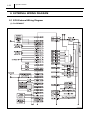
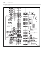
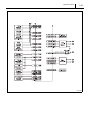
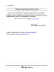
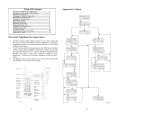
8. EXTERNAL WIRING DIAGRAM
8.1 ECU External Wiring Diagram
(1) For RENAULT
Operation Section
1 24
1 25
Operation Section
(2) For OPEL
Operation Section
1 26
Operation Section
1 27
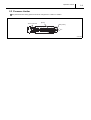
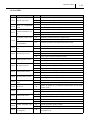
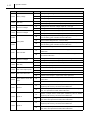
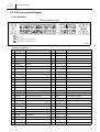
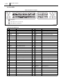
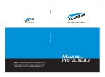
8.2 ECU Connector Diagram
(1) For RENAULT
ECU Connector Pin Layout
Terminal Connections (1)
No.
Pin Symbol
Connections
No.
1
+B
+B After
28
2
+B
+B After
29
3
GND
GND
4
P-GND
5
P-GND
Pin Symbol
Connections
THA1
Intake air temperature sensor (SIG)
30
MAF
Mass air flow sensor (SIG)
P-GND
31
A-GND
GND for sensor
P-GND
32
PL1-REL
Thermo plunger relay 1
FANB-REL
Fan control relay B
STA-SW
Starter SW
6
33
7
A-VCC1
5V (20mA) For sensors
34
8
ACCP2
Accelerator position sensor 2 (SIG)
35
9
36
10
CRUISE
Cruise SW
37
11
A-GND
GND for sensors
38
12
IJF2
EDU fail signal 2
39
13
MAFGND
Mass air flow sensor (GND)
40
14
41
15
42
16
CRUISE-GND GND for cruise control
43
17
PL3-REL
Thermo plunger relay 3
44
INJ5
Injector drive signal #5
18
FANA-REL
Fan control relay A
45
INJ3
Injector drive signal #3
19
GLOW
Glow controller
46
INJ1
Injector drive signal #1
48
CAN1L
CAN communication (-)
49
MONGL1
Glow diagnosis 1
ISO-K
KW2000 K-Line
20
21
47
BK2-SW
Brake SW2
22
23
SPDLIM-SW
Speed limit SW
50
24
IG-SW
Ignition SW
51
25
52
26
53
27
ACCP1
Accelerator position sensor 1 (SIG)
54
Operation Section
1 28
Terminal Connections (2)
No.
Pin Symbol
Connections
55
No.
89
56
PL2-REL
Thermo plunger relay 2
90
57
FANC-REL
Fan control relay C
91
Pin Symbol
Connections
VSS
Swirl control
VSV
Intake shutter
58
92
59
93
PIM
Turbo pressure sensor (SIG)
60
94
PEGR
EGR lift sensor (SIG)
61
95
A-GND
GND for sensor
62
96
63
INJ6
Injector drive signal #6
97
64
INJ4
Injector drive signal #4
98
A-VCC2
5V (100mA) for sensor
65
INJ2
Injector drive signal #2
99
THW
Coolant temperature sensor (SIG)
66
IJF1
EDU fail signal 1
100 THF
67
CAN1H
CAN communication (+)
101
68
MONGL2
Glow diagnosis 2
102 G SIG
Cylinder recognition sensor (SIG)
69
103 G GND
Cylinder recognition sensor (GND)
70
104 G +5V
Cylinder recognition sensor (+5V)
71
105
72
106 PFUEL
Rail pressure sensor (SIG1)
73
107 PFUEL
Rail pressure sensor (SIG2)
74
108
75
109 THO
Oil temperature sensor
Fuel temperature sensor (SIG)
76
M-REL
Coil: main relay
110 NE SIG
Crankshaft position sensor (SIG)
77
A-VCC3
5V (30mA) for sensors
111
Crankshaft position sensor (GND)
NE (GND)
78
112 NE +5V
Crankshaft position sensor (+5V)
79
113
80
114 EGR+
EGR valve actuator +
81
SPDREG-SW
Speed regulate SW
115 LSEGR
EGR valve actuator -
82
VSS-SW1
Swirl control valve SW1
116 SCVCOM
SCV common
83
VSS-SW2
Swirl control valve SW2
117
84
118
85
CAN2-H
Turbo
86
THA2
Intake
119
air
temperature
sensor 120 SCV2
SCV2
121 SCV1
SCV1
(boost)
87
A-GND
GND for sensor
88
CAN2-L
Turbo
Operation Section
1 29
(2) For OPEL
ECU Connector Pin Layout
Terminal Connections (1)
No.
Pin Symbol
Connections
No.
1
+B
+B After
28
2
+B
+B After
29
3
GND
GND
4
P-GND
5
P-GND
Pin Symbol
Connections
THAMB
Ambient temperature sensor
30
MAF
Mass air flow sensor (SIG)
P-GND
31
A-GND
GND for sensor
P-GND
32
LTERM
Alternator L-terminal I/O
FLEVEL
Fuel level sensor
ACR-REL
A/C relay
6
33
7
A-VCC1
5V (20mA) for sensors
34
8
ACCP2
Accelerator position sensor 2 (SIG)
35
9
36
10
PAC
A/C pressure sensor
37
11
A-GND
GND for sensor
38
12
IJF2
EDU fail signal 2
39
13
MAFGND
Mass air flow sensor (GND)
40
14
FRETURN
Fuel level return
41
15
CASE GND
ECU case GND
42
16
43
17
FAN2-REL
Fan control relay 2
44
INJ5
Injector drive signal #5
18
FAN1-REL
Fan control relay 1
45
INJ3
Injector drive signal #3
19
GLOW
Glow controller
46
INJ1
Injector drive signal #1
20
BATT
Battery
47
21
BK1-SW
Brake SW1
48
CAN1L
CAN communication (-)
22
49
MONGL1
Glow diagnosis 1
23
50
GLOW-L
Glow indicator
24
ACC
Accessory input
51
25
52
26
53
27
ACCP1
Accelerator position sensor 1 (SIG)
54
Operation Section
1 30
Terminal Connections (2)
No.
Pin Symbol
Connections
No.
55
STA-REL
Starter control relay
89
56
FAN3-REL
Fan control relay 3
90
57
Pin Symbol
Connections
VSS
Swirl control
91
58
TEXH1
Exhaust temperature sensor 1
92
59
TEXH2
Exhaust temperature sensor 2
93
PIM
Turbo pressure sensor (SIG)
60
PDPF
Differential pressure sensor
94
PEGR
EGR lift sensor (SIG)
61
CL-SW
Clutch SW
95
A-GND
GND for sensor
62
RUN
Supply from run/crank relay (IG-
96
SW)
63
INJ6
Injector drive signal #6
97
64
INJ4
Injector drive signal #4
98
A-VCC2
5V (100mA) for sensor
65
INJ2
Injector drive signal #2
99
THW
Coolant temperature sensor (SIG)
66
IJF1
EDU fail signal 1
100 THF
Fuel temperature sensor (SIG)
67
CAN1H
CAN communication (+)
101 PTHR
Throttle position sensor
68
MONGL2
Glow diagnosis 2
102 G SIG
Cylinder recognition sensor (SIG)
69
103 G GND
Cylinder recognition sensor (GND)
70
104 G5V
Cylinder recognition sensor (+5V)
71
105
72
MIL
Check engine warning light
106 PFUEL
Rail pressure sensor (SIG1)
73
107 PFUEL
Rail pressure sensor (SIG2)
74
108 POIL-SW
Oil pressure SW
75
109 THO
Oil temperature sensor
76
M-REL
Coil: main relay
110 NE SIG
Crankshaft position sensor (SIG)
77
A-VCC3
5V (30mA) for sensors
111
NE (GND)
Crankshaft position sensor (GND)
78
A-GND
GND for sensor
112
NE5V
Crankshaft position sensor (+5V)
79
BK2-SW
Brake SW2
113
LOIL-SW
Oil level SW
80
114 EGR+
EGR valve actuator +
81
115 LSEGR
EGR valve actuator SCVCOM
82
VSS-SW1
Swirl control valve SW1
116
83
VSS-SW2
Swirl control valve SW2
117 THR+
Throttle actuator +
118 THR-
Throttle actuator -
84
85
CAN2-H
Turbo
86
THA2
Intake
SCVCOM
119
air
temperature
sensor 120 SCV2
SCV2
121 SCV1
SCV1
(boost)
87
A-GND
GND for sensor
88
CAN2-L
Turbo
1 31
Operation Section
Published
: April 2006
Edited and published by:
DENSO CORPORATION
Service Department
1-1 Showa-cho, Kariya, Aichi Prefecture, Japan