1
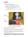
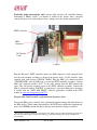
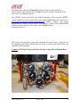
Ku and C Band DFTS D50 Maintenance Procedure
Version 2.0
Introduction
It is recommended that CPI’s Ku and C -band Klystrons equipped with D50 Digital Fast
Tuning Systems (DFTS) are cycled every 6 months (more often if environment is harsh
i.e. airborne dust and chemicals, high humidity) to ensure that the operation is smooth
and reliable. A suggested cycling sequence is:
1.
2.
3.
4.
Select lowest frequency channel
Select highest frequency channel
Select lowest frequency channel
Return to original channel
The tuning time for steps 2 and 3 should be 1 second or less. If cycling indicates any
hesitation, time-outs, or errors, then re-lubrication according to these instructions is
recommended.
.
The purpose of this document is to outline a Service Procedure for DFTS tuner
sticking/jamming troubles that occur in spite of regular cycling preventative maintenance.
The DFTS Service Procedure is to be implemented at CMP Georgetown or at approved
CPI service centers. Customer implementation of the Service Procedure is at the
customer’s own discretion. Should the customer decide to perform this operation, CPI
cannot be responsible for any damage to the Klystron by incorrect application of the
procedure or by improper handling of the klystron.
The Service Procedure will take a few hours. It should be implemented by qualified
technicians with knowledge about CPI klystron products. The successful maintenance of
the tuner may be very difficult to perform while it is inside the Klystron Power Amplifier
(KPA). The option of taking the Klystron out of the KPA (pulling the Klystron out on the
slides) prior to implementing this procedure should be seriously considered.
If the Klystron/KPA is in the power-on state, it needs to be powered down in a controlled
manner as described in the operation manual allowing sufficient time for the collector to
cool.
Implementation of the DFTS maintenance procedure should be considered when the
Klystron is more than 1 Year old or hasn’t been serviced (lubricated) in the last 12
Months.
Warning: High voltage should not be applied of any time during the maintenance
procedure! All KPA safety precautions must be strictly followed. Please see KPA
service manual for details.
CPI Confidential V 2.0
June 14, 2010
1
This procedure required the following tools:
• Laptop Computer with DFTS-D50 “FELIX” software script
• PC Interface Cable (CPI P/N764058). Free upon request.
• Non-magnetic screwdriver, Philips - stubby (to remove cover)
• Screwdriver, Flat - thin (to fit into driving screw’s top split end)
• PTFE-based lubricants (i.e. Super-Lube brand)
o Syringe or original oil applicator (for oiling coupler threads)
o PTFE oil and grease
• Wooden tapered stick (e.g. toothpick) or plastic tapered to clean threads
Motor
Module
DFTS
controller
assembly
Thumbscrews – two on each side of the controller,
tightened on the right and left side Klystron bracket
DFTS Tuner Cycling Preventative Maintenance
The DFTS driving screws need to be rotated every 6 months, driving the coupler from
home position (lowest frequency) to furthest from home position (highest frequency).
Each time the Klystron/KPA power goes off and then on again, all tuner couplers are
automatically moving to the HOME position and then to the last active channel settings
(enabled through parameters 60 and 61).
CPI Confidential V 2.0
June 14, 2010
2
In many cases, the DFTS is left in one position for extended periods of time (i.e. as a
principle Klystron tuned to one permanent frequency or as a 1:N redundancy systems
where the Klystron is used as a backup that is seldom exercised).
Prolonged static exposure of the screw grease to environmental contaminants in the
atmosphere can lead to hardening of the grease surface. As a matter of ongoing
maintenance, irrespective of the remaining recommendations in this service procedure,
the DFTS driving screws should be rotated every 6 months as described above. Please
refer to the Digital Fast Tuner System Operating Instructions for implementation
(www.cpii.com/docs/related/37/dftsmanual.pdf).
DFTS Service Procedure
The DFTS controller assembly needs to be removed. This is done by disconnecting the
control cable from the D15 connector (already removed and not shown in the above
picture), loosening the four thumbscrews located on the side mounting plates, and
disconnecting and removing the DFTS controller from the motor module.
Caution: Care must be taken as you remove the DFTS controller because a D50
connector exists between it and the motor module.
Right side
controller bracket
screw
Tuner cover
Left side controller bracket screws
Left side tuner cover screws (also 2 on right side)
Ku-band DFTS tuner is shown on the above picture (C-band brackets look different).
CPI Confidential V 2.0
June 14, 2010
3
Preferably using non-magnetic tools, remove right and left side controller brackets
unfastening 2 Phillips screws1 per bracket as shown in the picture above, and then
remove the tuner cover, unfastening 4 screws, taking care in the strong magnetic field.
DFTS Controller
DB15
Connector
PC Interface
Cable
Couplers
Plug the Klystron’s DFTS controller (make sure D50 connector is fully engaged) back
into the motor module assembly as shown in the picture above. Use PC interface cable
supplied with each klystron (CPI P/N 764058). Plug the DB15 (f) connector marked
“CONTROLLER” into the DB15 (m) port on the DFTS controller assembly. Connect
DB15 (m) connector marked “A2J7” to the cable coming from the KPA marked the
same. This will provide required power to the DFTS controller assembly. Connect the
DB9 (f) connector marked “LAPTOP” to your laptop’s serial port. Make sure your laptop
is loaded with the “DFTS D50 FELIX” software application, available from CPI’s
website at www.cpii.com/product.cfm/7/37.
Plugged cable should resemble configuration in the picture above.
Turn on the KPA power (stand-by only), ignoring the channel change link fault shown on
the KPA display. Under normal circumstances, the DFTS tuner should first automatically
move to the HOME position and then to the last active channel settings (if enabled
1
The fasteners supplied with Klystron are stainless steel. These cannot be replaced with ferrous fasteners as
they will disturb the magnetic field profile leading to potentially damaging defocusing of the Klystron
electron beam.
CPI Confidential V 2.0
June 14, 2010
4
through parameters 60 and 61). If the motors are struggling to execute this, give them a
hand. A gentle turn of the struggling pulley in the same direction the motor is trying to
turn should suffice. Be extremely careful doing this!
Caution: Do NOT place fingers inside the belt loop as the pulley could pinch them.
Motor side
Ku –band Klystron
Couplers are in the
highest frequency
position (end of
tuner travel)
Ku Band Klystron Side (high frequency direction)
The picture above shows the Ku-band Klystron tuner (motor module) with the cover
removed. The couplers are moved to the highest frequency position. Threads of the
driving screws are not exposed.
Motor
side
CPI Confidential V 2.0
C-band Klystron
Couplers are in the
highest frequency
position (end of
tuner travel)
June 14, 2010
5
The picture above shows the C-band Klystron tuner (motor module) with cover
removed. The couplers are moved to the highest frequency position. The threads of the
driven screws are partially exposed.
Start “FELIX” software application. For detailed instruction on how to operate “FELIX”
software including password please refer to the supplied DFTS Manual or download it at
http://www.cpii.com/docs/related/37/dftsmanual.pdf. FELIX software will enable
computer-based control over the DFTS screw/coupler positions. Enter PASSWORD
(A1984) and then send tuner (all couplers) to the HOME position
entering parameter “Z”
If the motors are struggling to execute this command, give them a hand. A gentle turn of
the struggling pulley in the same direction the motor is trying to turn should suffice. Be
extremely careful doing this!
Caution: Do NOT place fingers inside the belt loop as the pulley could pinch them.
CPI Confidential V 2.0
June 14, 2010
6
Now turn the KPA power OFF. This removes the holding current from the motors,
making the next step much easier. Remove the DFTS controller. Insert the flat-head
screwdriver in the slotted shaft of each axis and turn it four turns clockwise as shown in
picture above2. This moves the plungers behind home and ensures that any dried or dirty
grease is moved out of the active area of the threads.
Optical sensor
Home position, marker
top at least halfway
into the optical sensor!
Now rotate each of the slotted shafts at least four turns counter-clockwise, in order to
move optical sensors down - back to home position area. See the pictures above.
Re-attach DFTS controller and re-apply KPA power. Once the tuner initialization is
complete, use “FELIX” software to select the highest frequency channel as shown in
picture below. Power KPA off one more time and remove DFST controller.
There are total of five driving screws/coupler tops to be serviced. Use the flat screwdriver
to rotate driving screw counter-clockwise to the end of the tuner travel in order to get
access to the thread. This will allow some limited access to the driving screw thread to be
lubed.
Caution: Be careful when driving couplers manually into the high frequency
(counter-clockwise) direction. The Klystron bellows will be completely retracted/
squeezed, and applying excessive torque can damage the Klystron/tuner mechanism.
The thread should now be lubed with PTFE-based oil (e.g. “Super Lube” Synthetic oil
with Syncolon (PTFE). For more information please go to: www.super-lube.com.
2
Care must be taken while turning screw. Too much torque applied to on screws can damage tuner driving
mechanism and klystron’s internal components.
CPI Confidential V 2.0
June 14, 2010
7
Use the original Super Lube oil applicator (syringe) to oil threads. Any suitable (clean)
syringe filled with oil, could be also used. Apply very small amount (one drop at a time),
in order to mix oil with the original grease, repeat few times.
Oil can be applied directly to partially exposed threads on the C-Band DFTS. However,
there is very limited access to the threads of the Ku-Band DFTS tuner driving screws. As
a result, oil needs to be applied as follows
Apply oil to Ku-Band DFTS directly to the outer cavities threads, to cavity #1 (input)
from the bottom and to cavity #5 (output) from the top. Excess of the oil delivered to 5th
cavity could drop to the threads (below) of cavities #4, 3 & 2 and possibly lube them.
The inner cavities (2-4) driving screw threads are hidden between the optical switches
assemblies, and the very short Ku klystron plunger travel (max. 0.200”) doesn’t allow
moving the DFTS couplers further, away from the Home position.
The direct access to these cavity threads might be only through the small threaded holes
in the tuner couplers, located opposite to the Home position markers/targets. Use
wooden/plastic tapered stick (e.g. like a toothpick) to remove dried/contaminated grease
from the holes if necessary. Using metal needles might damage the thread coating. Drops
of the oil might be also carefully applied to the (hidden) driving screw thread, above
coupler with the wooden/plastic stick. See picture below for details.
Caution: Care must be taken – oil dropped on the optical switches will contaminate
them. Do not spray - overdosing of oil can also contaminate optical sensors!
Rotate tuner screw a couple of revolutions back to distribute oil to the driving screw top
end (home area) and then in the opposite direction a few times. Oil again if necessary.
CPI Confidential V 2.0
June 14, 2010
8
Syringe (nozzle)
inserted into the
coupler hole.
Home position
marker/target
Hole on the
opposite side.
Coupler hole
(1,3,5 cavity)
First & fifth cav.
access to the
thread area (above
the coupler top)
C-Band DFTS
Syringe
Nozzle
C-band screw’s thread
cleaned with toothpick
CPI Confidential V 2.0
June 14, 2010
9
Syringe to be used
for applying oil.
Please do NOT spray any solvent directly as it may damage optical sensor.
Do NOT use cotton Q-tips to clean threads.
This could leave cotton fibers on the threads.
Re-attach DFTS assembly and apply power to KPA. Using “FELIX” software exercise
the DFTS by selecting a routine of running from “HOME” to the lowest freq. channel
(usually #49 or 48.) to highest freq. channel (#50) to “HOME” for at least ten cycles.
This can be done using the “TUNER CYCLING” function in the “TUNING” menu of the
“FELIX” software.
If the DFTS achieves this faultlessly, run the KPA down and rebuild using the reverse
steps of the process detailed previously.
If the DFTS gets stuck at any point, or errors are reported on “FELIX”, repeat the
cleaning and lubrication procedure and retest.
Note: As a guideline, travel between the furthest physically apart channels should take
about 1 second with well functioning DFTS. Channel change faults will not be shown on
the KPA until this time exceeds 5 seconds. The “HOME” process will take longer than 30
seconds but only happens when KPA is powered on or driven with “FELIX”.
The Factory Support
During business hours 8:30am–5:00pm EST please call Customer Service at 1-905-7022203.
For all other times please call our JETSAT hot line 1-800-267-JETSAT (5387).
CPI Confidential V 2.0
June 14, 2010
10